Abstract
In high speed, high load fluid-film bearings, the laminar-turbulent flow transition can lead to a considerable reduction of the maximum bearing temperatures, due to a homogenization of the fluid-film temperature in radial direction. Since this phenomenon only occurs significantly in large bearings or at very high sliding speeds, means to achieve the effect at lower speeds have been investigated in the past. This paper shows an experimental investigation of this effect and how it can be used for smaller bearings by optimized eddy grooves, machined into the bearing surface. The investigations were carried out on a Miba journal bearing test rig with Ø120 mm shaft diameter at speeds between 50 m/s–110 m/s and at specific bearing loads up to 4.0 MPa. To investigate the potential of this technology, additional temperature probes were installed at the crucial position directly in the sliding surface of an up-to-date tilting pad journal bearing. The results show that the achieved surface temperature reduction with the optimized eddy grooves is significant and represents a considerable enhancement of bearing load capacity. This increase in performance opens new options for the design of bearings and related turbomachinery applications.
1. Introduction
In high-performance turbomachinery, the maximum bearing temperatures can be a crucial parameter. If these temperatures approach the critical values for the bearing metal and the lubricating oil, the operational safety and long-term reliability of the whole system may be at risk. The continuous demand for increased bearing loads, often in combination with rising rotor speeds, leads to an increase of the maximum bearing temperatures which can be the limiting factor for this development trend. This situation creates the motivation to improve fluid-film bearings by reducing their maximum temperatures and thereby push the limits for turbomachinery development.
In contrast to other means for achieving lower bearing temperatures, the phenomenon of the laminar-turbulent flow transition in high load regions of the fluid-film directly reduces the maximum oil film temperatures and thereby also the maximum bearing metal temperatures considerably, as for example measured in [1,2].
Typically, the laminar-turbulent flow transition occurs if a critical speed is exceeded, under otherwise constant operating conditions. The most important effect of this transition is the occurrence of radial flow velocities, approximated by an eddy, which means an increase of the apparent heat conductivity of the lubricating oil. Figure 1 shows an exemplary temperature distribution radially across the oil film at the position of the highest bearing temperature for two speed cases, one with laminar flow and the other one, after the flow transition, with Taylor vortex and turbulent flow, predicted for a sliding speed difference of only 1 m/s. The eddy conductivity at Taylor vortex and turbulent flow leads to a relatively even temperature distribution, in contrast to the high temperature gradients at laminar flow. As depicted, non-laminar flow can cause a reduction of maximum oil film and bearing metal temperatures.
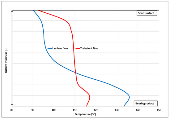
Figure 1.
Exemplarily predicted laminar and turbulent flow profiles across the oil film at the position of the highest bearing temperature.
In practice, a significant drop in the maximum bearing temperature can be observed when the fluid-film flow at the bearing hot-spot becomes non-laminar [1,2]. In this context, the term ‘hot-spot’ refers to the position of the highest bearing metal temperature. To take this temperature reducing effect into account in the design phase, the bearing calculation tool must predict and consider the local flow regime reliably for the given operational parameters of a bearing. State-of-the-art thermo-elasto hydrodynamic lubrication (TEHL) tools, like the ones described in [3,4], have implemented turbulence models for the local flow regime prediction, for example based on [5,6,7,8].
Due to its correlation with the fluid-film thickness, the local state of the lubricant flow is, for a given siding speed, fundamentally depending on the bearing diameter and, due to its effect on the local film thickness and local viscosity, on the bearing load. Figure 2 depicts these relations. As expected, a decrease of the bearing size and a rise of the bearing load, lead to an increase of the flow transition speed.
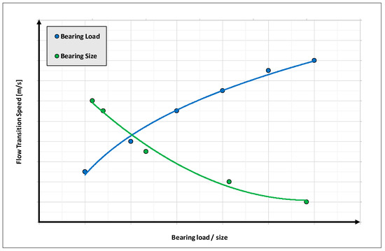
Figure 2.
Predicted qualitative influence of the bearing load and the bearing size on the laminar-turbulent transition speed.
According to these predictions and based on the experience that a significant temperature drop is practically observed only in high-speed turbomachinery with large rotor diameters >≈450 mm, it can be concluded that the natural flow transition speeds of smaller bearings operating at high loads are above most operating conditions.
To use the temperature reducing effect of non-laminar flow nevertheless, an approach to reduce the flow transition speed is necessary. In [9] this idea was realized by milling a high number of specific grooves into the surface of a Ø500 mm bearing to disturb the laminar flow and thereby cause the desired increase of radial flow components at reduced sliding speeds, respectively reduced local Reynolds-numbers.
The experiment was successful. The maximum temperature measurements of the 4-tilting pad test bearing were considerably reduced, though not evenly for both loaded pads and by trend less effective at increased loads. However, based on this investigation, the flow regime in the fluid-film of a bearing can be influenced and the desired reduction of flow transition speed can be achieved.
However, for a broader use of this concept, several questions were left unanswered. The most important aspect is the scope of application, regarding the bearing size, sliding speed and specific bearing load. Other open points are the definition of an optimum groove geometry in terms of performance and manufacturing complexity and the specification of an effective arrangement of single grooves to a complete pattern.
To provide a contribution to these open questions, an experimental test project was decided and carried out on a Miba Industrial Bearings test rig.
2. Test Equipment
2.1. Test Rig
For the experimental investigations, the Ø120 mm high-performance journal bearing test rig depicted in Figure 3, was used. The electric motor drives the shaft (1) via a spur gear and a curved-tooth coupling (2). The shaft is supported by two fixed-profile support bearings (3, 4) located in the test rig housing (5). The test bearing (6) is held by the bearing carrier (7) and is located centrally between the support bearings. The bearing carrier is connected to the test rig housing by chains (8). The chains serve to align and axially fix the test bearing. The load is applied by a metal bellow (9) which is pressurized with compressed air. The resulting load is transferred to the bearing carrier via the traverse (10) and the connections rods (11) and is measured by a load cell (12). The vibration exciters (13) for generating dynamic loads were not required for the project described.

Figure 3.
(a) Journal bearing test rig front view photo; (b) test rig core sectional drawing.
The main data of the rig is shown in Table 1.

Table 1.
Test rig main data.
The maximum speed of 20,000 rpm corresponds to a sliding speed of 125 m/s and the maximum load of 63 kN results in a maximum specific bearing load of 7 MPa for an axial bearing length of 75 mm.
2.2. Test Bearing
As much of today’s high-performance turbomachinery is equipped with tilting pad bearings, an up-to-date 5-tilting pad bearing was selected for the experimental investigations. Table 2 includes the bearing properties.

Table 2.
Test bearing main data.
The bearing was installed with load between pads (LBP) orientation. For an accurate measurement of the maximum pad temperatures, the loaded pads were equipped with a dense arrangement of thermocouples near the trailing edge and close to the axial midplane as shown in Figure 4, and thus in the area where the highest temperatures and temperature gradients occur.
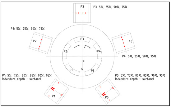
Figure 4.
Bearing orientation and thermocouple locations.
At each defined circumferential position, two thermocouples were placed, one soldered into the bearing metal, with approximately 0.3 mm radial distance to the sliding surface and a second 1 mm below the white metal, corresponding to approximately 4 mm below the sliding surface for this bearing size, the same distance as the typical 75% sensor position of customer bearings. Thus, one temperature sensor in each pad of the test bearing is placed very similar to the standard sensor of customer bearings.
The sensors located 1 mm below the white metal were used for a comparison with reference data from older investigations, which were carried out without surface temperature sensors and as a backup solution if problems with the more sensitive surface temperature measurement would have occurred. In addition, information is obtained on how the temperature situation at the bearing surface affects the 75% standard position or other measuring points at the same depth, since in the field, measurements directly at the bearing surface are not practicable, mainly for safety reasons.
For the bearing alignment control, additional temperature probes were installed near the axial edges of the loaded pads.
Figure 5 shows the assembled test bearing.
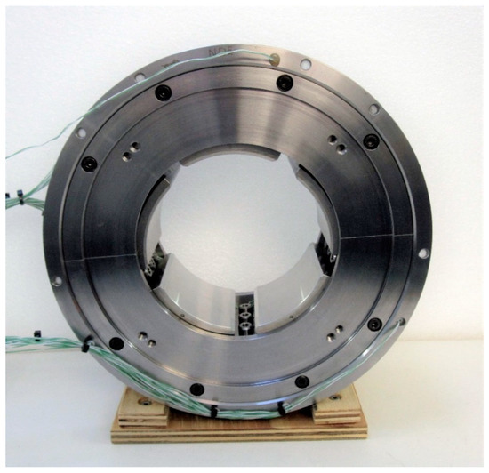
Figure 5.
Assembled test bearing with plain pad surfaces.
2.3. Eddy Grooves
After the completion of the test program with plain pads, the loaded pads were re-machined and equipped with eddy grooves. According to the details described in [10], eddy grooves are physical grooves in a specific area of a pad with a particular shape, arranged in a particular pattern, as shown in Figure 6a for the test bearing. The bearing assembly with eddy grooves is shown in Figure 6b.
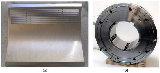
Figure 6.
(a) Pad with eddy groove arrangement and (b) assembled test bearing.
The grooves are designed to disturb the laminar oil flow regime, which is typically present in this area of a bearing, causing high bearing temperatures, especially at higher loads. In circumferential direction, the adjacent grooves maintain the flow disturbance to keep-up the non-laminar status. In axial direction, the grooves are interrupted twice and end with a distance to the edges to prevent a drop of hydrodynamic pressure or load carrying capacity, respectively.
It should be mentioned that, from the authors’ point of view, the described eddy grooves and their influence on the physics of hydrodynamic lubrication are not part of the topic of surface texturing as introduced in [11] and further investigated, for example, in [12]. The distinction is made by the shape, the position and the significantly larger geometric dimensions of the grooves, e.g., the depth is considerably higher than the minimum oil film thickness at higher loads. Accordingly, the mode of action is not aimed at increasing the hydrodynamic pressure or the reduction of friction losses but rather to influence the flow regime at typical turbomachinery steady-state points of operation at full fluid friction.
2.4. Test Program
The tests program was defined according to Table 3.

Table 3.
Test program.
The rate of oil flow was individually set for each sliding speed. To investigate the influence of the lube oil flow rate, medium, low, and high rates were defined, based on the oil temperature difference between outlet and inlet. For the medium flow rate, an oil temperature increase of 20 K–22 K was defined. For the high flow rate, 15 K–17 K, and for the low flow rate, 25 K–28 K, oil temperature increases were defined.
The actual number of test points was approximately 200 for the test bearing with plain pads as well as for the eddy groove bearing, as not all parameter combinations could be tested, mainly due to the limitations of the oil supply system.
3. Results and Discussion
3.1. Plain Bearing
To verify the prediction of the natural flow transition speed, an initial test was carried out in which the shaft speed was incrementally increased, with otherwise constant parameters. The result of the temperature measurements is shown in Figure 7. The predicted and measured transition speeds are in good agreement, while the predicted temperature drop is significantly higher than the experimentally observed value. Despite this difference, the test confirms that the flow transition occurs, even at this moderate load of 1.5 MPa, at speeds considerably above normal operating conditions.
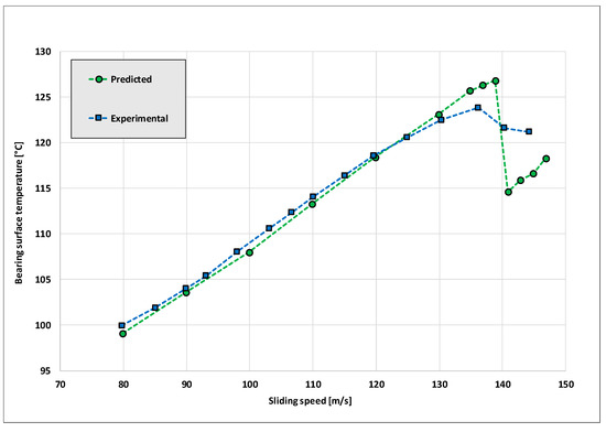
Figure 7.
Experimental and predicted temperature development at stepwise rotor speed-up for the 5-tilting pad test bearing at Tin = 56 °C, Q = 77 L/min and 1.5 MPa specific load.
The further focus of the plain bearing investigation was on the creation of a reference data base for the comparison with the eddy groove bearing.
In addition, the comparison between the soldered-in surface probe measurements and the probe measurements 1 mm below the white metal was carried out also for the plain bearing, although it is more important for the eddy groove bearing, because its results cannot be predicted with current calculation tools.
Figure 8 shows a typical measured temperature profile over all five pads, with separate data for the surface and standard depth probes in the loaded pads: while the maximum pad temperatures at the standard depth are 104 °C and 112 °C, respectively, the corresponding maximum surface temperatures are 113 °C and 126 °C.
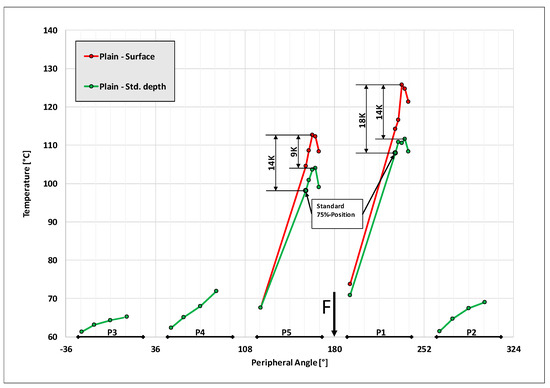
Figure 8.
Plain surface bearing: measured temperatures from surface probes (red graph) and standard depth probes (green graph) at v = 90 m/s, 3.0 MPa specific load, Tin = 45 °C and medium oil flow rate.
A comparison of these values with the temperatures measured at the standard 75%-position, 1 mm below the white metal, underlines the importance of taking the surface temperatures into account for the evaluation of the operational safety of the bearing: while the maximum temperatures at the standard depth are only 5 K/4 K above the 75%-position measurement, the difference to the surface is 14 K/18 K for this point of operation.
Under comparable conditions, Hagemann et al. [13] also reported significant differences between the maximum surface temperature and the 75%-position below the white metal.
Figure 9 summarizes the differences between surface and standard depth temperatures, individually for both the max temperature and the 75%-position temperature as a function of the specific bearing load by averaging all measurements taken at the same bearing load at rotor speeds between 50 m/s–110 m/s.
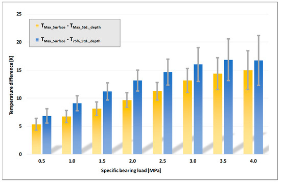
Figure 9.
Plain surface bearing: Load-dependent mean difference between the maximum surface temperature and the maximum standard depth temperature (yellow bars) and between the maximum surface temperature and the standard 75%-position temperature (blue bars) including the standard deviations (grey bars).
As expected, the temperature difference increases with rising bearing load. Due to the speed dependent oil flow rates according to the defined oil temperature rise, the influence of the rotor speed is insignificant.
At the standard sensor depth, 1 mm below the white metal, the difference between the maximum temperature and the 75%-position temperature is relatively moderate and constant, so that in practice a temperature sensor at the 75%-position can meet the requirements for measuring the relevant bearing temperature for condition monitoring.
3.2. Eddy Groove Bearing
While an impact of eddy grooves on the bearing’s power loss was not measurable, the attempt to reduce the maximum temperatures of the test bearing by provoking the transition of the otherwise laminar flow in the area upstream the lowest film thickness was successful. Due to the non-laminar flow regime induced by the bearing-specific eddy grooves, the maximum surface temperatures dropped considerably.
The effect was clearly visible at all tested speeds and increased with the bearing load and sliding speed. Figure 10 shows a measured temperature comparison over all five pads for a high speed, high load case: the eddy groove bearing develops 16 K/17 K lower maximum surface temperatures than the plain bearing. The temperature reduction at the standard depth is 13 K/10 K, which is lower than at the surface, but still significant.
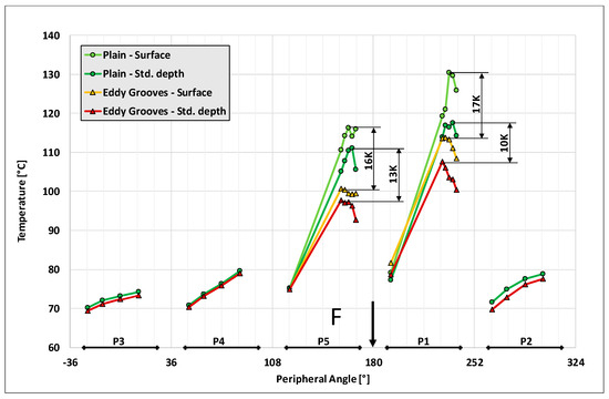
Figure 10.
Temperature distributions at the surface and at standard sensor depth for the eddy groove and the plain surface bearing at v = 100 m/s, 3.0 MPa specific bearing load, Tin = 55 °C and medium oil flow rate.
By averaging all measurements taken at the same load at rotor speeds between 50 m/s–110 m/s, Figure 11 summarizes the reduction of maximum surface temperatures and the standard 75%-position temperatures due to eddy grooves compared to the plain bearing: the eddy groove cooling effect at the bearing surface is strong, especially at high bearing loads, while the temperature reduction at the 75%-position is only moderate. The reduced impact on the 75%-position standard thermocouple measurement result was expected because the eddy groove effect takes place in the oil film near the bearing surface and naturally becomes smaller with increasing distance. However, the surface temperature reduction has the clear potential to be used to increase the safety margin or power density of a bearing.
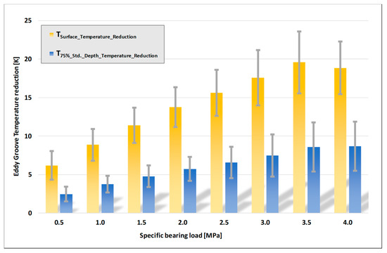
Figure 11.
Temperature reduction by eddy grooves compared to the plain surface: Load-dependent mean differences for the maximum surface temperatures (yellow bars) and for the 75%-position standard depth temperatures (blue bars), including the standard deviations (grey bars).
This potential is illustrated in Figure 12: for the given operational parameters, the bearing with plain pads develops a maximum surface temperature of 110 °C, indicated by point 1 in the chart. Regarding accelerated oil aging and bearing issues based on oil carbonization, this temperature is not far from critical values.
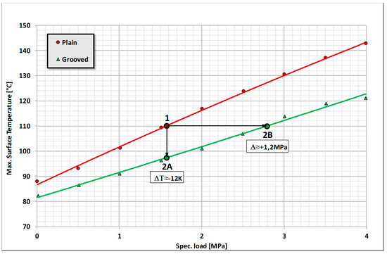
Figure 12.
Eddy groove application example at v = 100 m/s, Tin = 55 °C and medium oil flow rate.
With the eddy groove modification of this bearing, opportunities arise to either use the benefit solely for a temperature reduction by 12 K and thereby increase the operational safety of the bearing, indicated by point 2A, or to use the full benefit to increase the bearing load at a constant maximum temperature, shown as point 2B. A new point of operation between 2A and 2B would result, compared to point 1, in a reduced bearing temperature in combination with an increased bearing load.
Regarding the service life of eddy groove bearings, the investigation showed no indication that a reduction must be assumed. The bearing evaluation after the comprehensive test program with high loads and temperatures revealed no negative effects on the grooves, such as geometric changes caused by creeping. This may also be a consequence of the low creeping values of the used bearing material, but the reduced level of maximum bearing temperatures generally reduces creeping tendencies. In practical use, the usual mild wear, e.g., due to particle abrasion, is also tolerable, since the depth of the grooves is considerably above the permissible wear values.
Figure 13 summarizes the increase of bearing load capacity investigated in this project: with identical maximum surface temperatures, the bearing can carry a considerably higher load if it is equipped with eddy grooves.
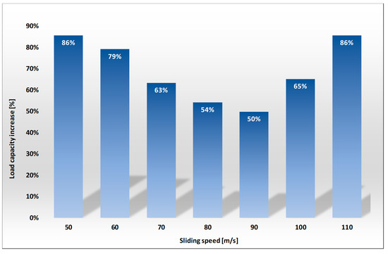
Figure 13.
Summarized temperature-related relative increase of load capacity by eddy grooves, compared to the plain surface. The figures represent the mean increase of bearing load capacity at the given sliding speeds for identical maximum surface temperatures.
4. Conclusions
For the improvement of operational safety and performance of fluid-film bearings, Miba developed and tested the patent pending eddy groove technology:
In highly loaded, high-speed fluid-film bearings, a laminar flow regime is typically present in the area upstream the lowest film thickness. Because of the low thermal conductivity of lubricating oil, this leads to high radial temperature gradients near the bearing surface, resulting in high bearing temperatures, while the gradients and thus the temperatures radially towards the shaft are considerably lower.
When exceeding a threshold speed, the transition of the laminar flow to Taylor vortex and turbulent flow creates additional radial fluid flow components which reduce the high temperature gradients. This results in a considerable temperature reduction near and at the bearing surface. The transition of the laminar flow thus significantly reduces the maximum bearing temperatures, which can have a very positive effect on the operational safety and load capacity of the bearing. However, the flow change is practically only observed in very large bearings, so that this natural effect is typically not achievable for most applications.
With Miba eddy grooves, the onset of non-laminar flow with significant radial flow components can be shifted to lower sliding speeds, so that the reduction of maximum temperatures, respectively the increase of the bearing load capacity can be achieved in the technically relevant sliding speed range of smaller bearings. The effectiveness of this technology was proved experimentally on a Miba journal bearing test rig on a Ø120 mm, 5-tilting pad bearing: in the entire test range at speeds between 50 m/s–110 m/s, and loads between 0 MPa–4 MPa, a significant reduction of maximum bearing temperatures due to eddy grooves was achieved, especially at higher bearing loads, under otherwise identical operating conditions. There was no noticeable influence on the power loss.
Temperature measurements directly at the bearing surface show the full potential of this technology to reduce the decisive maximum oil film and bearing metal temperatures, which is especially useful for high performance applications. Thereby, eddy groove bearings push the limits of safe operation considerably and open new technical possibilities.
The reduced bearing temperatures, induced by eddy grooves, can be used to:
- Increase the safety margin of the bearing and slow down the lubricating oil aging
- Operate bearings at higher loads without an increase of maximum temperatures
- Decrease the bearing diameter or the axial length to reduce the power loss and the necessary rate of oil supply without an increase of maximum bearing temperatures
Regarding the bearing size, eddy grooves have been successfully tested at bore diameters of 120 mm and 500 mm [9]. Above this range, the effectiveness of eddy grooves is as good as certain, if the laminar-turbulent transition hasn’t already occurred naturally. Below this range, it is assumed that eddy grooves also reduce the maximum temperatures of smaller bearings, while an accurate lower size limit is not yet determined. Miba eddy grooves can also be used for other bearing designs, like fixed-profile journal bearings. Further investigations of the eddy groove technology are planned.
Author Contributions
O.B. prepared the test rig and the test bearings. O.B. and E.S. conducted the experiments. E.S. analyzed the test data, wrote the draft and revised the manuscript. All authors have read and agreed to the published version of the manuscript.
Funding
This research received no external funding.
Data Availability Statement
Data only available on request due to protection of IP.
Acknowledgments
The authors would like to thank T. Hagemann and D. Schüler for their helpful advice and support of the manuscript revision.
Conflicts of Interest
The authors declare no conflict of interest.
References
- Hopf, G.; Schüler, D. Investigations on Large Turbine Bearings Working Under Transitional Conditions between Laminar and Turbulent Flow. J. Tribol. 1989, 111, 628–634. [Google Scholar] [CrossRef]
- Taniguchi, S.; Makino, T.; Takeshita, K.; Ichimura, T. A Thermohydrodynamic Analysis of Large Tilting-Pad Journal Bearing in Laminar and Turbulent Flow Regimes with Mixing. J. Tribol. 1990, 112, 542–548. [Google Scholar] [CrossRef]
- He, M. Thermoelastohydrodynamic Analysis of Fluid Film Journal Bearings. Ph.D. Thesis, University of Virginia, Charlottesville, VA, USA, 2003. [Google Scholar]
- Hagemann, T. Ölzuführungseinfluss bei schnell laufenden und hoch belasteten Radialgleitlagern unter Berücksichtigung des Lagerdeformationsverhaltens. Ph.D. Thesis, TU Clausthal, Clausthal-Zellerfeld, Germany, 2011. [Google Scholar]
- Ng, C.-W.; Pan, C.H.T. A Linearized Turbulent Lubrication Theory. J. Basic Eng. 1965, 87, 675–682. [Google Scholar] [CrossRef]
- Elrod, H.G.; Ng, C.W. A Theory for Turbulent Fluid Films and Its Application to Bearings. J. Lubr. Technol. 1967, 89, 346–362. [Google Scholar] [CrossRef]
- Hirs, G.G. A Bulk-Flow Theory for Turbulence in Lubricant Films. J. Lubr. Technol. 1973, 95, 137–145. [Google Scholar] [CrossRef]
- Constantinescu, V.N. Basic Relationships in Turbulent Lubrication and Their Extension to Include Thermal Effects. J. Lubr. Technol. 1973, 95, 147–154. [Google Scholar] [CrossRef]
- Hopf, G. Experimentelle Untersuchungen an großen Radialgleitlagern für Turbomaschinen. Ph.D. Thesis, Ruhr-Universität Bochum, Bochum, Germany, 1989. [Google Scholar]
- Schüler, E.; Berner, O. Hydrodynamic Sliding Bearing. Patent WO2021004803A1, 14 January 2021. [Google Scholar]
- Hamilton, D.B.; Walowit, J.A.; Allen, C.M. A Theory of Lubrication by Microirregularities. J. Basic Eng. 1966, 88, 177–185. [Google Scholar] [CrossRef]
- Henry, Y.; Bouyer, J.; Fillon, M. Experimental analysis of the hydrodynamic effect during start-up of fixed geometry thrust bearings. Tribol. Int. 2018, 120, 299–308. [Google Scholar] [CrossRef]
- Hagemann, T.; Zemella, P.; Pfau, B.; Schwarze, H. Experimental and theoretical investigations on transition of lubrication conditions for a five-pad tilting-pad journal bearing with eccentric pivot up to highest surface speeds. Tribol. Int. 2020, 142, 106008. [Google Scholar] [CrossRef]
Publisher’s Note: MDPI stays neutral with regard to jurisdictional claims in published maps and institutional affiliations. |
© 2021 by the authors. Licensee MDPI, Basel, Switzerland. This article is an open access article distributed under the terms and conditions of the Creative Commons Attribution (CC BY) license (http://creativecommons.org/licenses/by/4.0/).