1. Introduction
An indication of the reduced load-bearing capacity of the gearings is their growing wear. Increasing the capacity and the durability of the gearings is one of the problems, which can be solved during the design phase (by changing the geometry of the gearing) or technologically (using new materials or technologies).
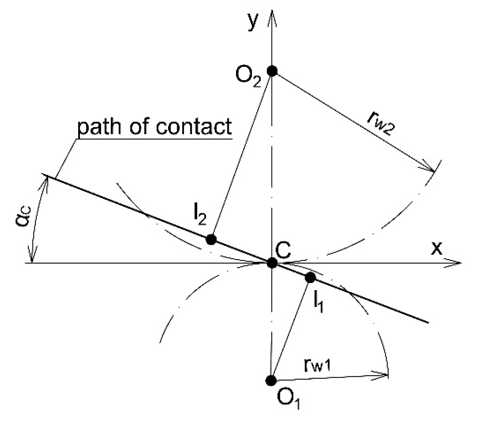
At present, the most widespread is the involute gearing, which has a straight-line path of contact (
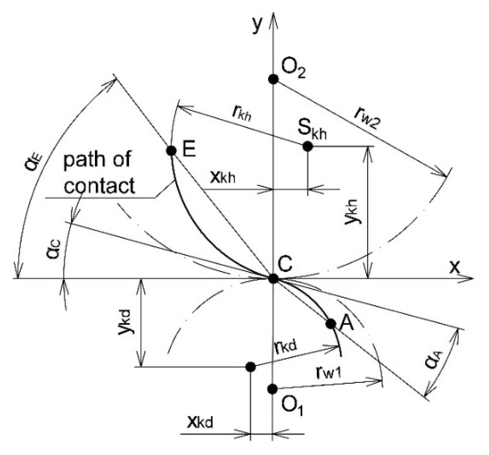
Figure 1), and the tooth flank has an involute shape. In the case of convex–concave (C–C) gearings, the path of contact is forming circular arcs (
Figure 2), and the tooth flank has the shape of a general curve [
1,
2].
Non-standard C–C gearing design exhibits smaller contact pressures, lower slip ratio and higher contact load capacity [
3,
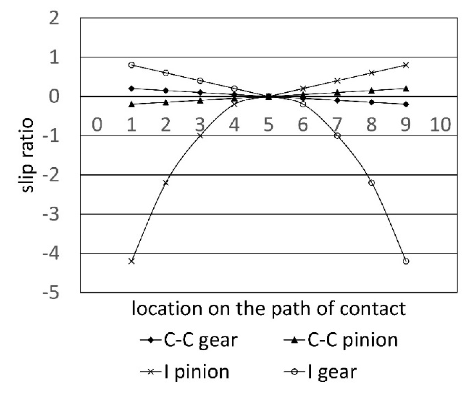
4]. The surface bearing capacity of the tooth flank is influenced by the size of the contact pressures and the size of the slip ratio. The comparison of involute (I) and convex–concave (C–C) gearings in terms of slip ratio is shown in
Figure 3. The C–C gearing has a significantly lower slip ratio compared to the involute gearing, especially on the addendum and dedendum of the tooth flank.
Torque generates power contact in gearings, which involves high pressure values at the contact points between the tooth flanks. The magnitude of this pressure is an important indicator for the surface damage of the tooth flank and thus also for the life of gearings.
This fact is confirmed also by the computational simulation of load in convex–concave and involute gearings from the point of view of contact in the ANSYS software module on the base of geometrical and calculation models [
2]. The contact pressure analysis shows that C–C gearing has 25% lower pressure in contact teeth than involute gearing. These findings were confirmed by experiments on the Niemann test stand [
5] for scuffing. When using Biogear S 150 lubrication oil scuffing was observed at the 8th load stage while in convex–concave gearing it occurred at the 10th load stage. When using Biohyd MS 46 oil scuffing occurred at the 8th load stage, while in C–C gearing at the 9th load stage.
The technological approach to increasing the load-bearing capacity of gearings includes various sophisticated technologies, including chemical and heat treatment methods [
6]. On the steel parts, the wear resistance is increased by applying surface layers [
7], even at higher temperatures [
8], as are corrosion resistance [
9] and resistance to combined stresses [
10].
Thermoset polymers were widely used as high-performance coatings in many industrial applications due to their thermal stability, chemical and wear resistance [
11]. Chemically and mechanically resistant thermoset polymers are frequently used as specialized coatings on substrates for heavy duty work such as laboratory benches, automotive parts and construction materials [
12].
With the development of material engineering during the last few years several technologies of application of thin coatings such as PVD, CVD, PACVD and others have been used, whose aim is to increase the load capacity of gearings. From the above- mentioned experiments it is clear that the deposition of hard thin coatings on the surface of the tooth flank is one-way of increasing load capacity, which also increases the load capacity of gearings for the required lifetime [
13,
14,
15,
16]. The selection of a suitable coating for application in the gearing, due to the specific conditions of the teeth contact, is a demanding process which is affected by a whole range of factors. In their application to the gearing following requirements are:
resistance to high pressures produced during the mesh of the gears;
sufficient adhesion of the coating on the surface of the gear for the selected materials;
resistance to temperatures up to values of 450 °C, occurring during the gear mesh;
maximum roughness of the teeth flanks in the produced gears is Rz 0.7 µm;
minimum surface hardness of the teeth flanks is 55 HRC;
low value of the coefficient of friction of the selected coating: 0.4;
resistance of the coating to mineral, synthetic or organic oil.
The aim of this contribution is to determine the resistance of C–C coated gearings to scuffing. Two mono-coatings (TiN and TiCN), as well as one combined TiCN + MoS
2 coating, were used. TiN and MoS
2 were tested on involute gearing [
14]. Our research is focused on identifying the mechanism of surface wear in specific conditions for C–C gearings.
2. Materials and Methods
Experimental samples and gears were made of C45E steel containing 0.57%–0.65% C, 0.5%–0.8% Mn and 0.15%–0.4% Si. This type of steel is suitable for hardening. It is used to produce less loaded toothed gears, pins, spindles and machine parts requiring enhanced abrasion resistance.
Scuffing tests were done on C–C gears manufactured by chip machining, with a roughness of 1.0–1.3 µm. For the application of layers, a minimum of approximately 0.5–0.7-µm roughness of the tooth flank is required (as demanded by the supplier). As these were non-standard gears, special devices, unavailable during the experiment, should have been used to achieve the required roughness of the tooth flanks. Therefore, coating was preceded by a running-in procedure of the test gearings when still soft [
15] to achieve the required roughness. Subsequently, the surface of the teeth was laser quenched which is currently the most suitable method for gearing (tooth side curve) and tempered at 450 °C. The objective was to obtain the required surface hardness of the tooth flank (substrate) capable of resisting the strain of layer deposition under high contact pressures (Hertz’s pressures in gear teeth).
The material coatings included TiN, TiCN and TiCN + MoS
2 combined coating. TiN coatings are used in various technical applications due to their great hardness and thermal stability [
16]. Due to their high resistance to corrosion and wear along with a decorative appearance, the coatings are used in engineering applications [
17]. Titanium carbonitride (TiCN) is characterized—in addition to great hardness and wear resistance—by a high degree of toughness. Therefore, it is suitable for interrupted loading [
18,
19]. Due to superb sliding properties, molybdenum disulfide MoS
2 is used as a lubricant. In addition, it is also used to create the top layers in combined coatings in gearings [
14,
20]. In gearings, this layer can form a sliding layer in contact with the teeth.
TiCN and TiN coatings were applied by arc–ion-plating (AIP) technology using the arc at a cathode current of 100 V, at a substrate temperature of 420 °C during one hour. Since the substrate tempering temperature (450 °C) was higher than the coating temperature (420 °C), no metallurgical changes in the substrate structure occurred. The MoS2 coating was applied by the magnetron sputter-ion-plating (MSIP) method. A fifty-volt substrate bias voltage and 0.4 Pa argon pressure were applied. The deposit time was two hours at a substrate temperature of 80 °C. The coating thickness was measured by the electron microscope.
The thickness of the deposited coating and its chemical composition were determined by SEM and EDX analysis, respectively. The adhesion of the coatings to the substrate was monitored by a scratch test by means of a CSEM REVETEST test device. The scratch tests were carried out at a constant speed of the moving sample and at a constant increase in normal force from 1–100 N. During the test, the acoustic emission signal dependence of the normal force was recorded. The influence of the coefficient of friction on normal force was also determined by this device. The nano-hardness of the coatings was determined at 2.5-mN and 0.5-mN loads. The depth of penetration of the indentor into the sample was also observed.
Tribological evaluation of the thin coatings was performed on CSM Instrumental equipment by the Ball-on-disk method. The counterpart was an Al2O3 ball. Tests were performed dry at a 1-N load at a sample rate of 80 mm/s on a 100 m track. The wear and friction coefficient were determined by the tribological characteristics. The wear was measured by the material weight loss and the friction coefficient from the frictional and normal force fraction.
The load-bearing capacity of the sealing coatings was determined by a Niemann tester (FZG test) with enclosed power flow [
21] (
Figure 4). This device was made in the workspace of authors of the Institute of Transportation Technology and Design. The gears were tested under increasing load. The criterion for completing the test is to achieve the scuffing point of load, which corresponds roughness of Rz greater than 7 µm on the tooth flank.
At present, great attention is paid to the effect of lubricants on increasing the load-bearing capacity of gears [
22] as well as the application of low friction coatings on metal substrates [
23]. The tested gearings worked in interaction with an ecological OMV Biogear S 150 ISO VG 150 lubricant, which is according to [
24] suitable for rotating parts operating under load. For comparison, the second test lubricant was Biohyd MS 46 ISO VG 46 hydraulic oil (the geared device is combined with a hydraulic transducer). The aim of testing this oil was to verify the possibilities of its application in the gearings.
Wear was analyzed by SEM on the cross-sections and the surface of the side of the tooth. The geometry of the worn surfaces was monitored by the measurement of the surface roughness.
3. Results
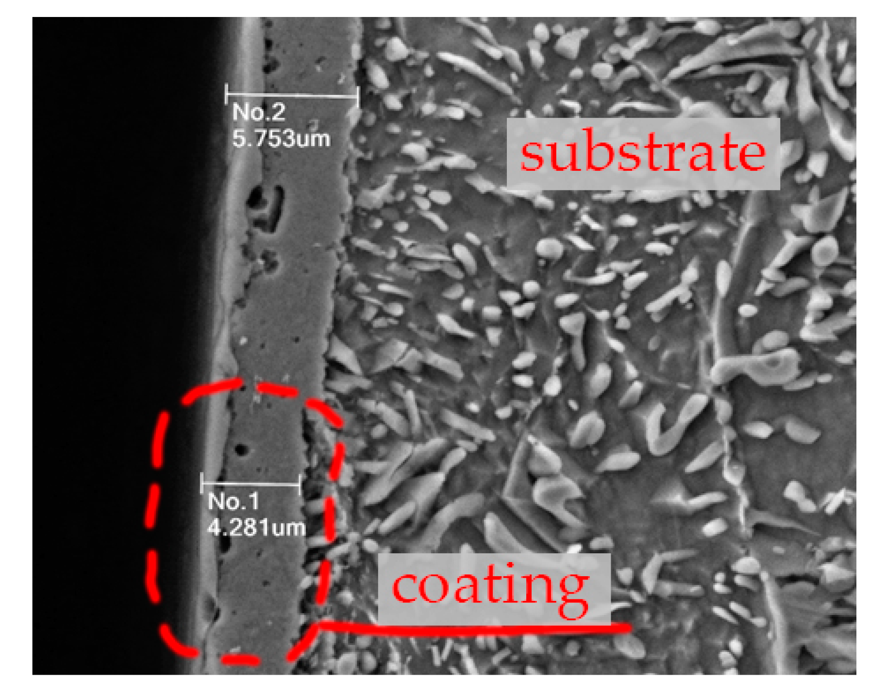
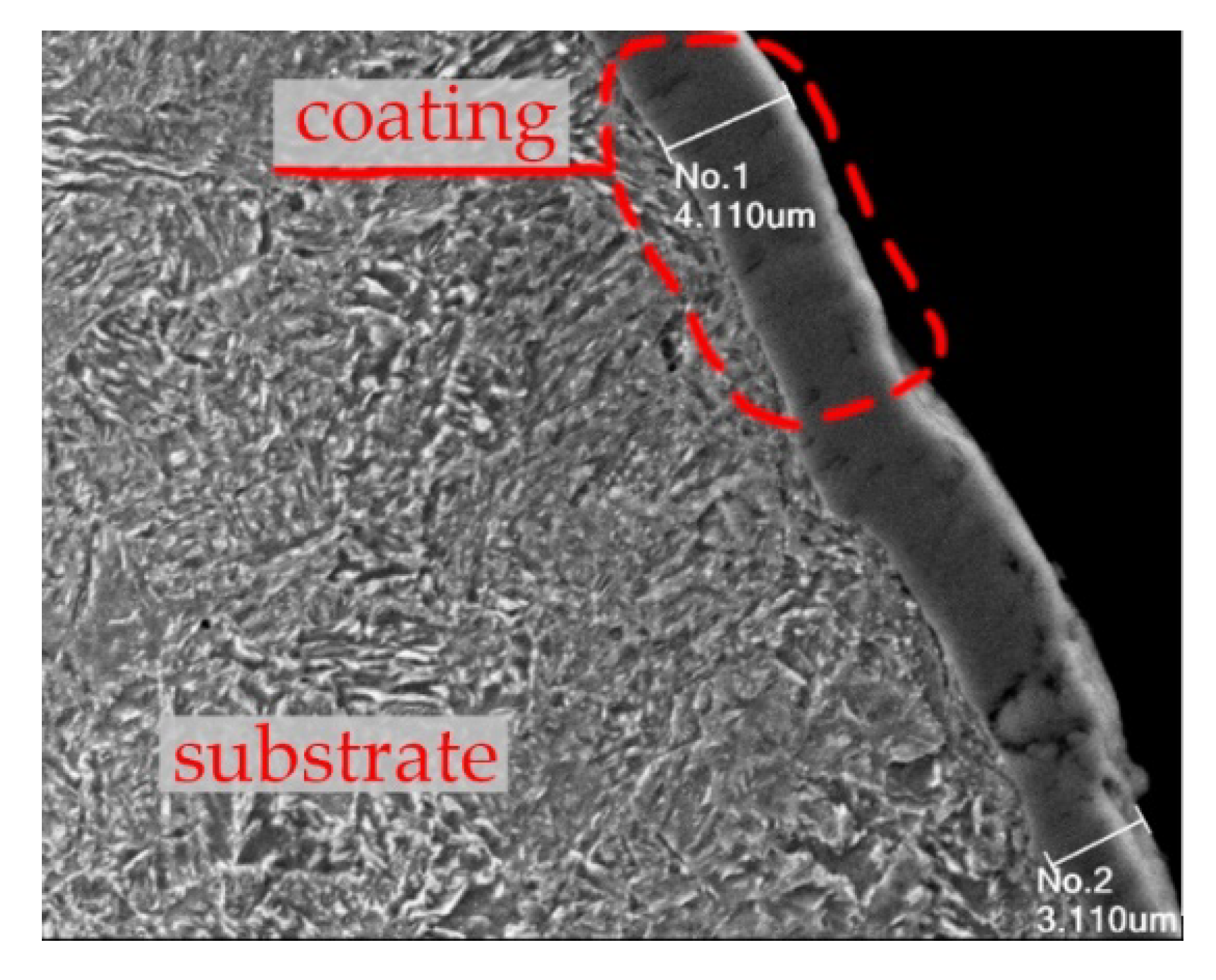
The thickness of the TiCN and TiN layer was detected on cross section of tooth. The thickness of TiN layer was within the range 4.2–5.8 µm (
Figure 5), and the thickness of the TiCN layer was 3.1–4.2 µm (
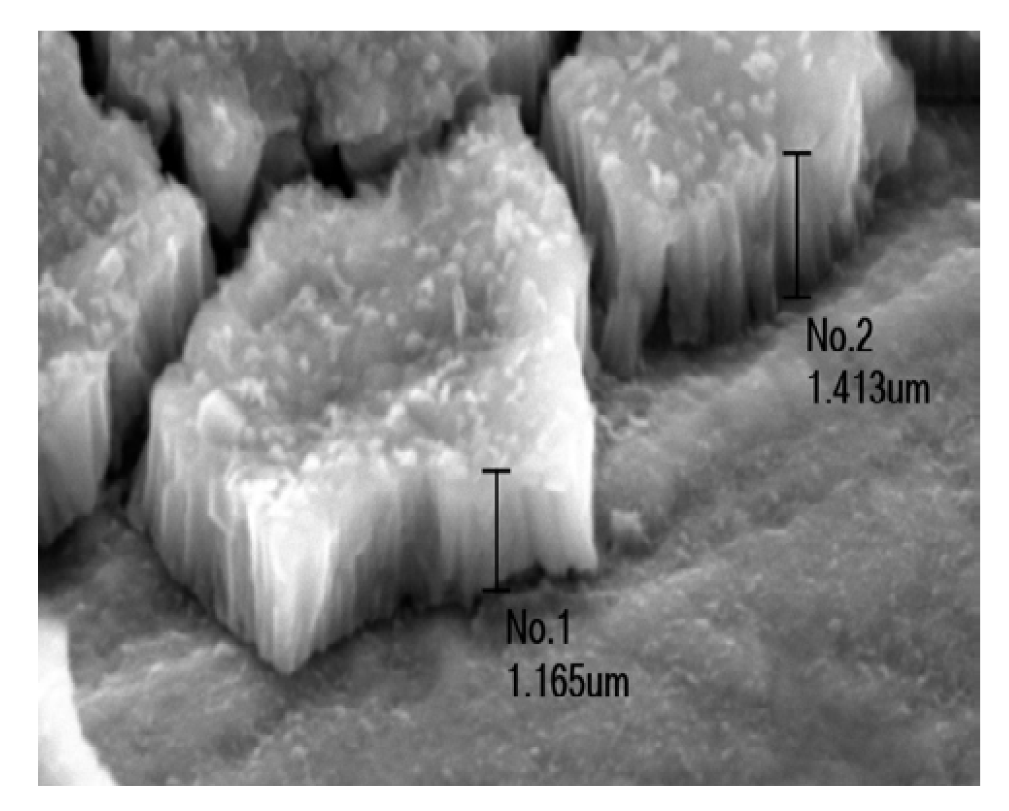
Figure 6). The thickness of the molybdenum disulfide layer was difficult to measure in the cross section because it was soft and thin. We detected it at the edge of the worn layer and had a thickness of 1.1–1.5 µm (
Figure 7).
The measured layer thickness of MoS
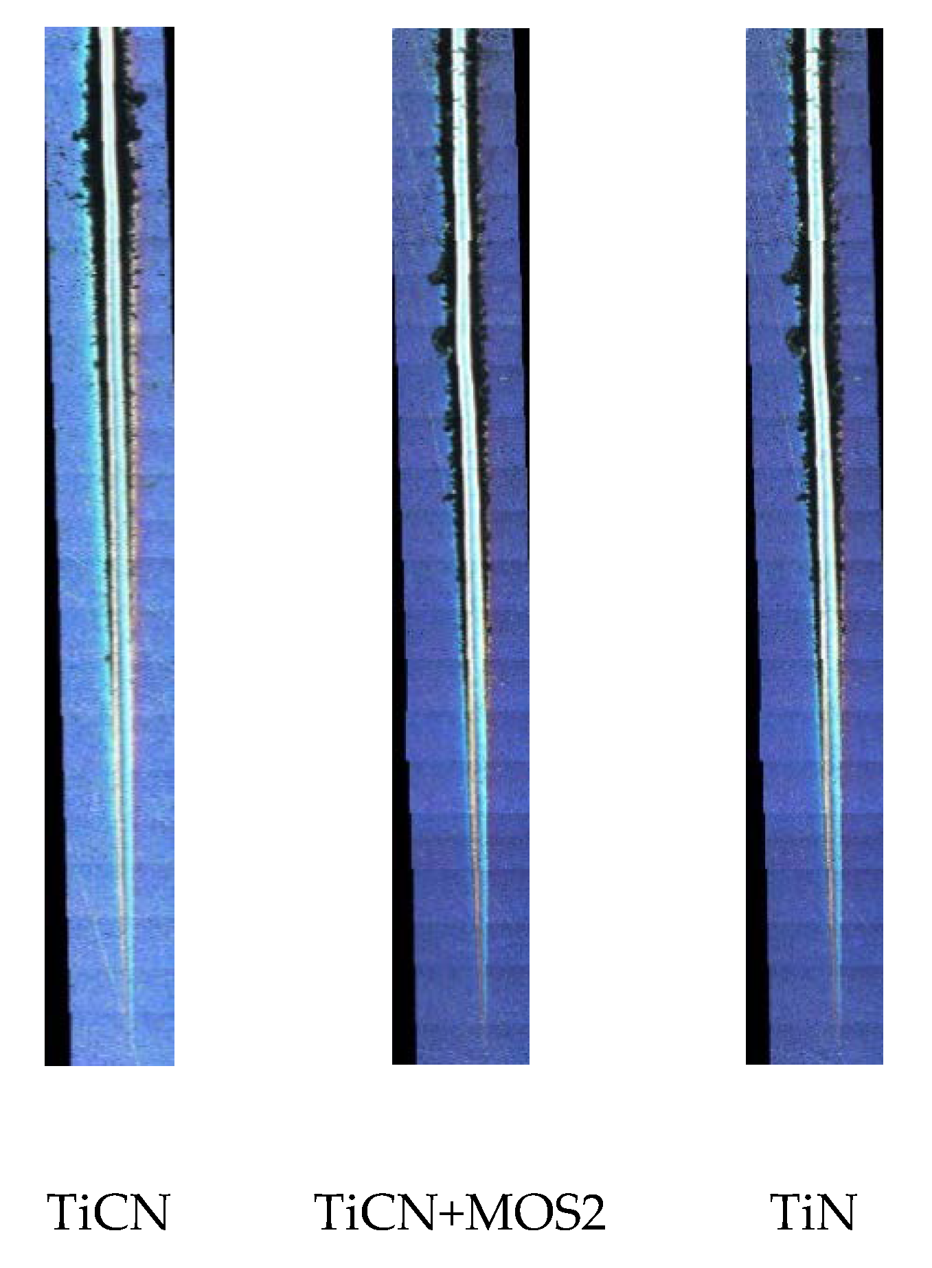
2 was also confirmed in nano hardness tests. In
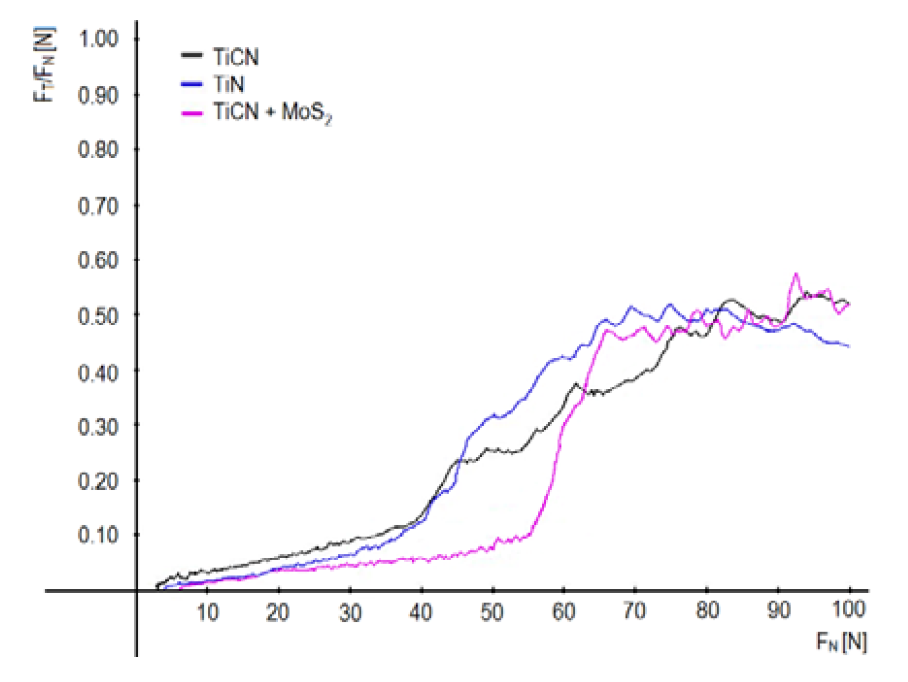
Figure 8 are illustrated the traces after a scratch test. The wider traces on samples with the TiN coating prove the lower hardness of the layer, as was confirmed in the hardness measurement. Changes of friction coefficient during scratch tests are shown in
Figure 9. However, at a load of about 40 N, the friction coefficient increased from 0.1 to 0.5 to remove the coating. This value corresponds to the coefficient friction of the substrate. In the case of the combined TiCN + MoS
2 coating, the first phase with a low coefficient of friction is longer. This is due to the good sliding properties of the MoS
2 layer.
The combined coating has a smaller coefficient of friction due to the presence of MoS
2 layers on the surface. The stabilization of the friction coefficient at approximately the same values for all the coatings tested at near normal force greater than 68 N is caused by the indenter penetration into the substrate. When further increasing the load, only the friction coefficient of the substrate steel ASTM A576-B1 was recorded. Delamination of the TiN coating was recorded approximately at a load of 50 N. Adhesion of the TiCN layer to the steel substrate was slightly better; its separation occurred at a load of 54 N. Scratch tests have shown comparable adhesion of coatings as with other types of layers applied in gears [
25]. The reason for coating delamination is a sudden change in chemical composition at the interface between the layer and the substrate.
The elimination of the negative influence of sudden change in chemical composition on the triological characteristics at the interface between the coating and substrate can be achieved, for example, by creating a layer using surface hardening processes (chemical–thermal treatment) [
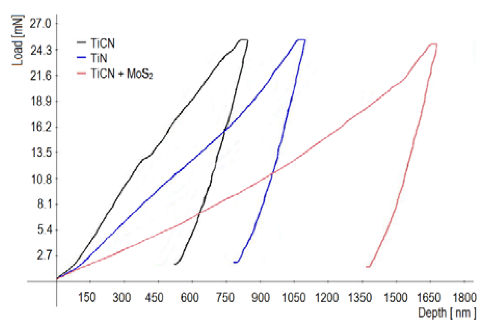
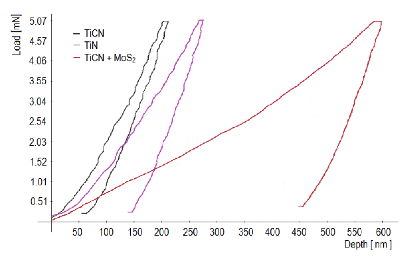
26]. The nano-hardness of the coatings was determined at loads of 2.5 mN and 0.5 mN. Identical values of nano-hardness (4.1–4.3 GPa) were measured at the highest load due to indenter penetration into the substrate in all the layers. For the above reason,
Figure 10 shows the dependence of the depth of indentation only from the load of 2.5 mN and
Figure 11 from the load of 0.5 mN.
From
Figure 10 it is apparent that at a load of 2.5 mN the indenter penetrated the combined layer through the 1650 nm coating of MoS
2 as far as the coating of TiCN. In addition, in the layers of TiCN and TiN, at a load of 2.5 mN the indenter penetrated deeper than one tenth of the thickness of the sample. The condition of indenter penetration to a maximum of one tenth of the thickness of the layers was fulfilled for TiCN and TiN layers at a load of 0.5 mN (
Figure 11). Hardness of the TiCN coating was 42 GPa, of the TiN 28 coating, 28 GPa, and of the combined coating, 32 GPa.
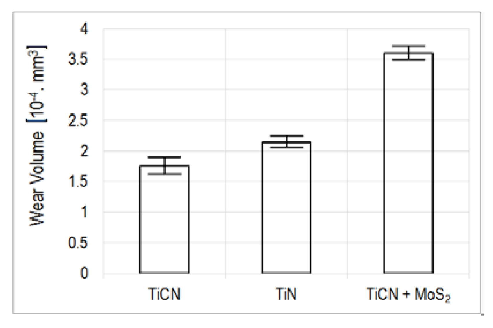
Wear and friction tests were performed on five samples.
Figure 12 shows changes wear volume of the evaluated layers with the identified variations. Their value did not exceed 8% of the mean value. Therefore, we consider the comparison of mean values to be correct.
Figure 12 shows the decrease in worn volume from the surface of the experimental coatings. It is apparent that the TiCN layer had about 8% higher resistance to wear than the coating of TiN. The combined coating exhibited the lowest resistance because of the soft MoS
2 surface layer. The layer of TiCN showed the highest wear resistance.
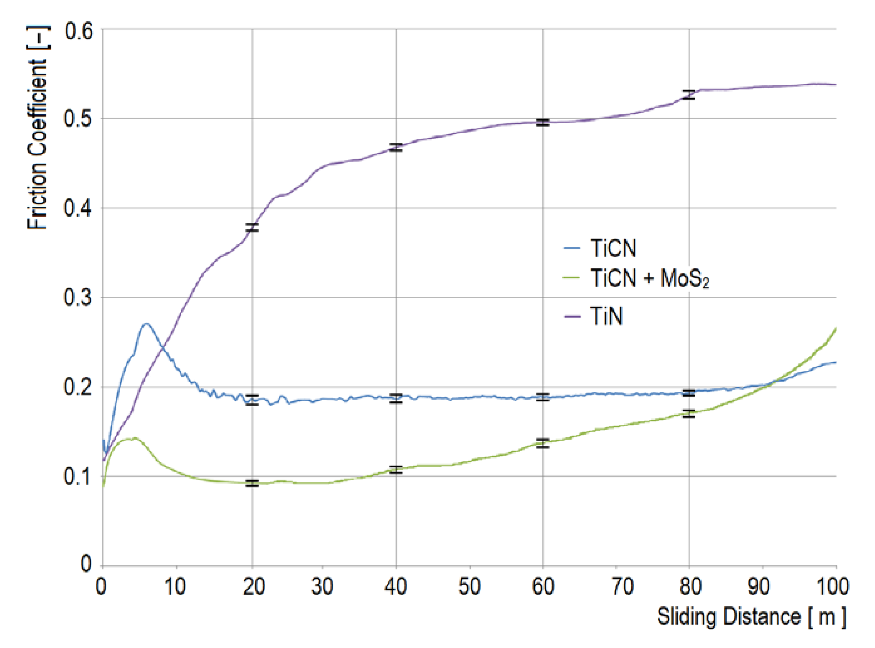
The friction coefficients of the layers depending on the length of the sliding path are shown in
Figure 13.
As is illustrated, they settled approximately after 14 m in case of TiCN and combined coating. The combined TiCN + MoS
2 coating showed a small friction coefficient (less than 0.1) after stabilization, but after approximately 35 m it began to grow significantly. The cause was the rapid wear of the soft, thin MoS
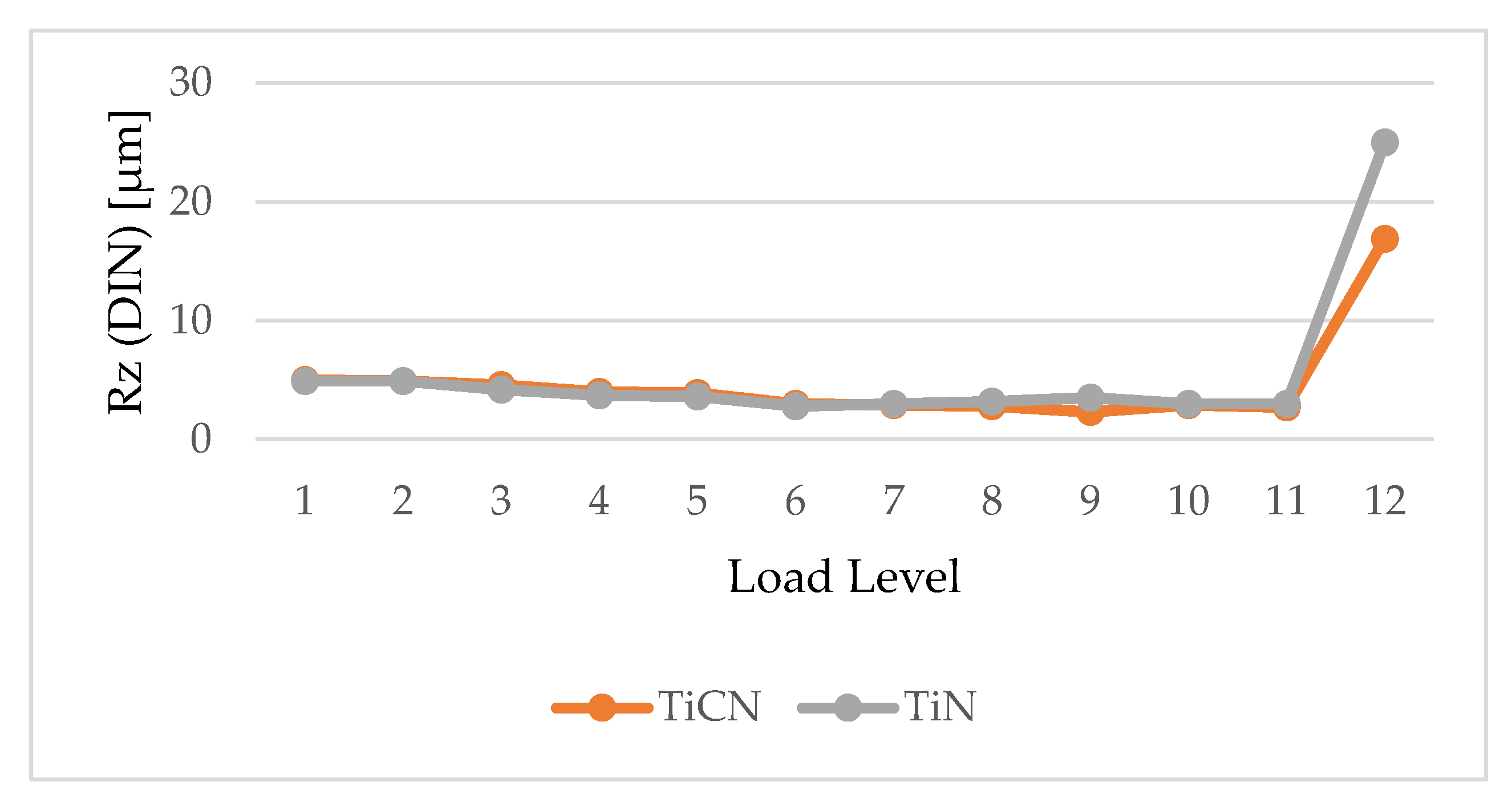
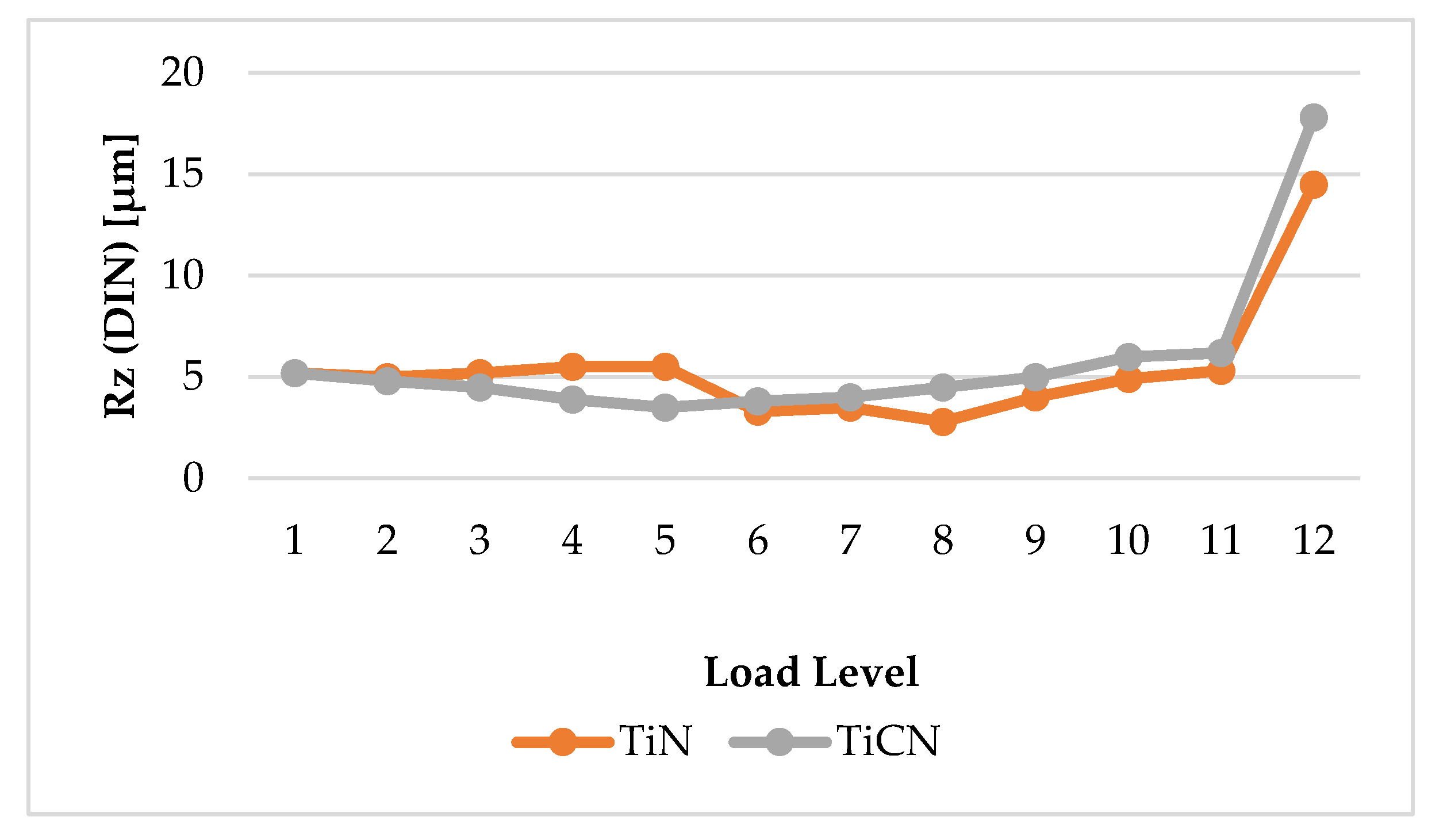
2 layer. The friction coefficient of the TiCN layer was also low, but almost doubled in comparison with the combined layer (0.2) at a track length up to 50 m, and subsequently it was increased. The TiN coating showed the highest friction coefficient, increasing in relation to the sliding path. Scuffing was evaluated based on the change in roughness depending on the stage of load. For Biogear S 150 oil, the roughness change is shown in
Figure 14 and for Biohyd MS 46 in
Figure 15. Metallographic examination of worn surfaces proved that roughness is dependent on the load stage. From the above figures it can be seen that the roughness changes for both oils are almost the same, scuffing occurred at 11 stages of load. With uncoated gearings, scuffing occurred at 8 load stages [
5]. The roughness change in
Figure 14 and
Figure 15 results from the measurement methodology FZG Test, ISO 14,635-1: 2000 (12 load stages). Their interconnection is made in order to access the trend change of Rz.
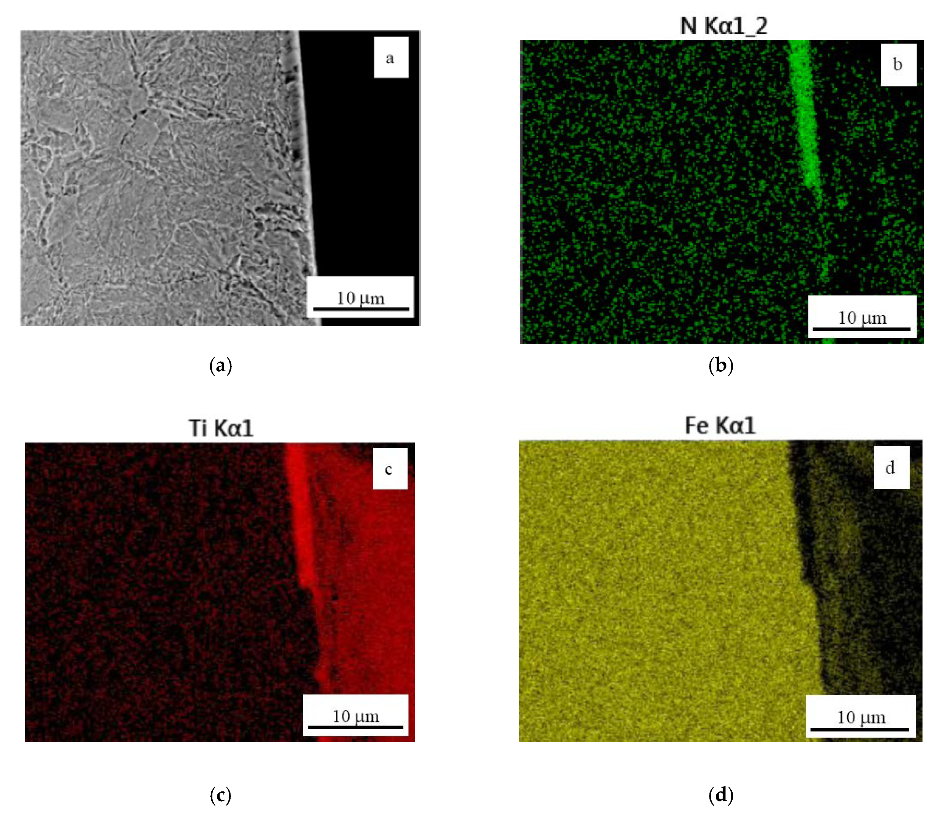
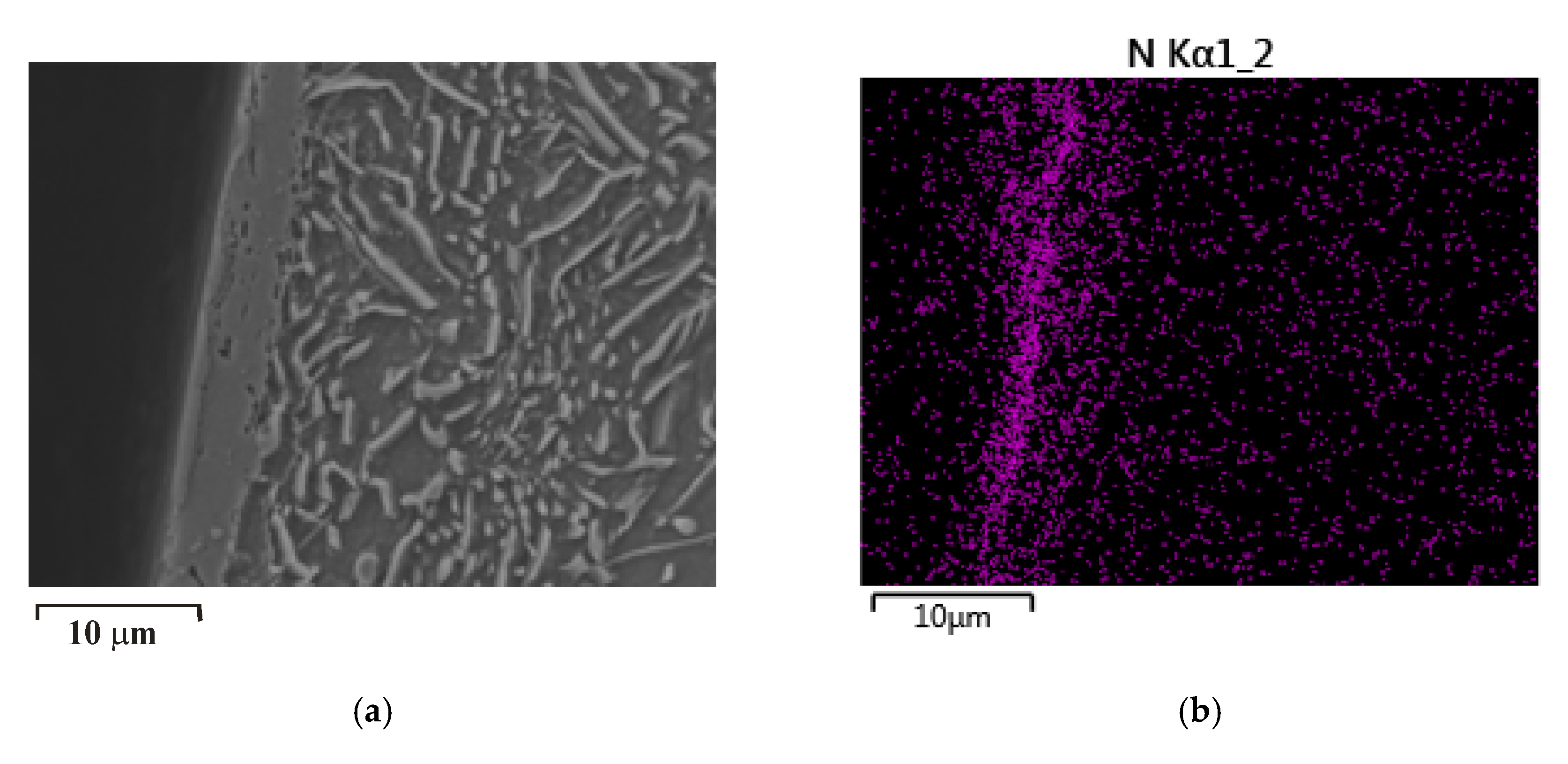
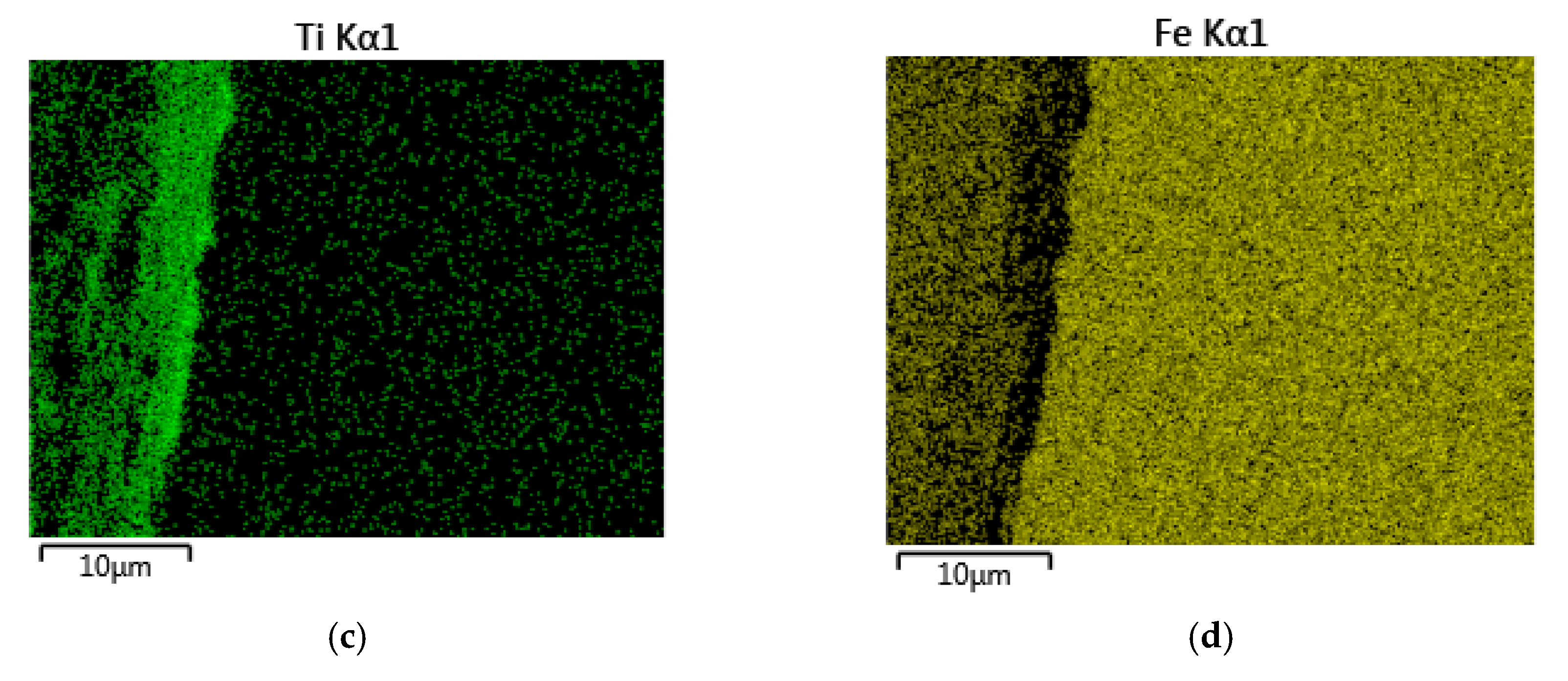
Figure 16 illustrates a cross-sectional view of the tooth coated with TiCN. In the top right parts of
Figure 16 the layer shows no wear. However, the wear decreases its thickness. The thinned layer was gradually pressed into the substrate and was subsequently eliminated.
Figure 16b–d illustrates EDS analysis of the tooth cross-section showing distribution of elements. Nitrogen and titanium, (
Figure 16b,c) are present only in the surface layers. Iron, (
Figure 16d) occurs only in the substrate.
A thin (1.1–1.5 μm) molybdenum disulfide coating cracked without prior removal of the layer, as is apparent from the detail of the worn MoS
2 layer (
Figure 7). The separation of the MoS
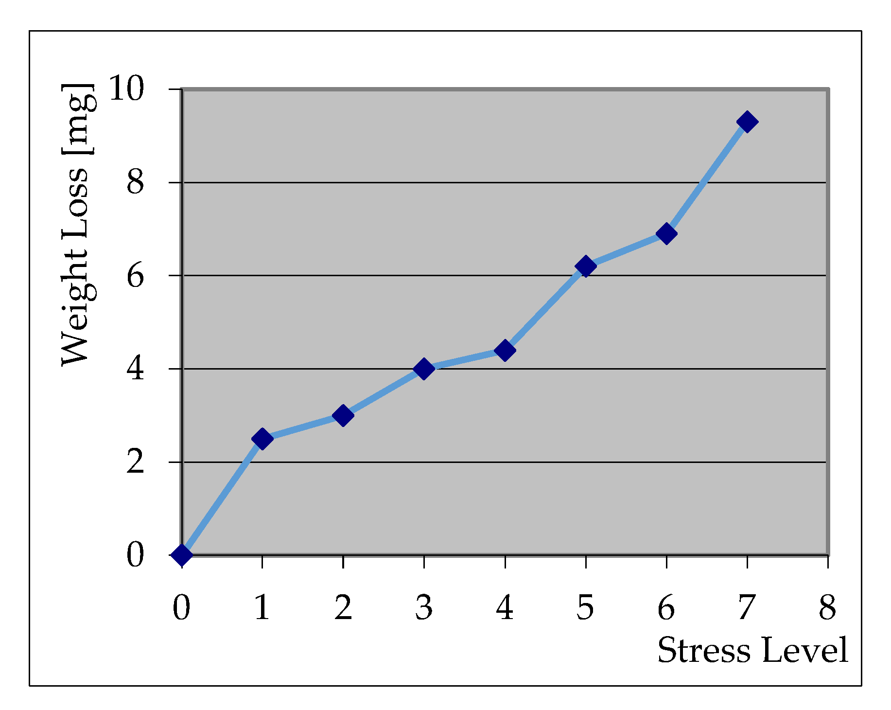
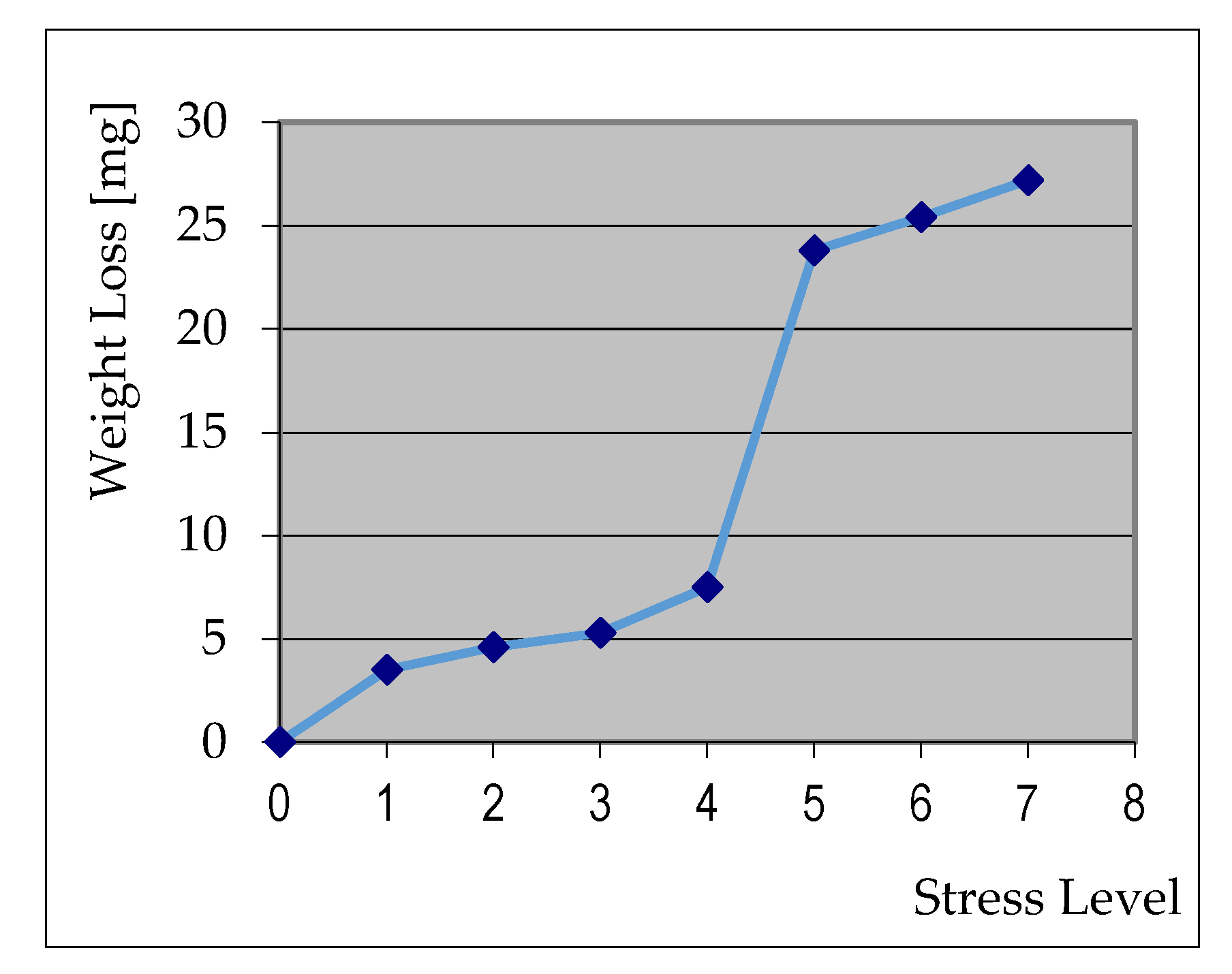
2 layer was identified by measuring the weight loss of the TiCN coating (
Figure 17), and TiCN + MoS
2 (
Figure 18) on the pinion. From the comparison of the results, it is clear that in the case of TiCN + MoS
2, the weight loss at the 5th load stage increased significantly. The weight loss in
Figure 17 and
Figure 18 results from the measurement methodology FZG Test, ISO 14,635-1: 2000 (12 load stages). Their interconnection is made order to access the trend change of weight loss.
Figure 19 shows the cross-section of the tooth flank with a TiN coating. Similar to the TiCN coating, the layers were first, removed from the TiN coating and subsequently the coating pressed into the softer steel substrate. In
Figure 20, on the interface between the worn TiN layer and the steel substrate, the different mechanisms of wear can be seen. In the direction of load, the material under plastic deformation in the protrusions gradually filled in the irregularities on the machined surface. Based on the above analysis, it can be concluded that a crucial feature for assessing the load-bearing capacity of the coatings of the gearing was the hardness of the layer and its thickness.
4. Discussion
Although in the case of C–C gearing, compared to involute gearing, there are lower contact pressures between teeth, they were too high for the softer and thinner MoS2.
The low friction coefficient of the MoS2 layer did not increase the load-bearing capacity of the combined layer, because the soft coating was rapidly separated from the substrate. As it cracked into soft fragments, it did not pollute the lubricant, but on the contrary contributed to the lubricating effect. The load-bearing capacity of TiCN and TiN coatings can be improved by increasing the hardness of the substrate, by tempering at lower temperatures, for example. It will slow down the process of depressing the layer into substrate, which prevents its removal and slows down the wear of the coatings and the steel substrate as well. Protrusion irregularities after machining will be plastically deformed later, which may reduce wear of the substrate. The possibility of increasing the hardness of the substrate by reducing the tempering temperature, must be experimentally verified for the examined material. There is a risk that at low temperature, the tempered layer of the substrate material would be further tempered at 420 °C during the application of TiCN and TiN coatings.
It turned out that lower contact pressures also caused rapid wear of the MoS
2 coating. A possible solution to this problem may be the preparation of a particle substrate containing a combination of hard material (TiN) and soft MoS
2 particles with a low friction coefficient [
27,
28]. The formation of scuffing for selected coatings documented in this article was solved of convex–concave gearing working also in interaction with Biogear S 150 and Biohyd MS 46 oils.
Teer Coatings applied MoS
2 to machine parts; we did not find the possibility of applying it to gears. This also because the gears are characterized by specific stress conditions in the teeth contact, which are not suitable for separate MoS
2 (high pressures, sliding speeds and temperatures [
1,
2]). For this reason, we used it only as a friction coating on TiCN. It is, of course, a matter of further research for its application to another hard coating.
The most common gearing failures are scuffing, pitting and fracture of the tooth. In this article we deal with the resistance of non-standard gearing to scuffing. The principle of the methodology of scuffing is based on tests on the Niemann tester, where the change scuffing depends on the change of roughness or weight loss. Therefore, we did not solve the problem of slip-rolling resistance.
5. Conclusions
This article analyzed wear of TiCN, TiN coatings, and a TiCN + MoS
2 combined coating deposited on C–C gearing made of ASTM A576-B1 steel. Scuffing tests were conducted on the Niemann tester. The thickness of TiN layer was within the range 4.2–5.8 µm and the thickness of the TiCN layer was 3.1–4.2 µm and the thickness of the MoS
2 layer in the combined coating was 1.1–1.5 µm. Scratch tests were performed to test adhesion and the influence of load force on the friction of the monitored coatings. The TiCN layer became detached at a normal loading of 54 N and the TiN layer at 50 N. For the TiCN layer the nano-hardness of 42 GPa, was measured, which was significantly higher than for the TiN layer that measured 28 GPa. The ball-on-disk test detected a greater durability in terms of wear of the TiCN coating, and it was about 8% higher in comparison with the TiN coating. The combined coating exhibited the lowest resistance to wear because of the soft MoS
2 surface layer. The basic laboratory method for investigating tribological properties is the ball-on-disk method. However, the results of the work [
13] have shown these laboratory results in the case of gears are only indicative and are finally confirmed in the gears tests.
The load-bearing capacity of coatings deposited on toothed C–C gearing lubricated with ecological Biogear S 150 and ecological hydraulic Biohyd MS 46 oils, was determined by scuffing tests on a Niemann tester. As regards the specific examinations of the coated wheels scuffing (wearing of coatings occurs first, subsequently tested wheels change their mass), the process of scuffing was examined not only from aspects of material loss, but also based on changes in roughness of the tooth on each load stage (the critical value was 7 µm). According to this criterion, it was established that scuffing started to occur close to the 11th load stage.
The main scientific contribution of this experiment lies in the clarification of the wearing process of coated teeth. TiN and TiCN coatings wore in the same way. Layers were removed from the coating which was simultaneously pressed into the steel substrate. The thin MoS2 coating cracked at light loadings, and subsequently broke down into micro-particles. Removed particles of MoS2 contributed to the lubricating effect of the used oil since they are commonly known as solid lubricants in the released form. The wear of the steel substrate started with the plastic deformation of protrusions of roughness caused by the milling operation. The plastically deformed volumes of metal filled cavities in the rough surface of the teeth after milling. It was most likely the reason for the high resistance of the gearing to scuffing.
It turned out that in the of C–C gears, even lower contact pressures caused a rapid wearing of the MoS2 coating. A possible solution to this problem may be the preparation of a particle substrate containing a combination of hard material (TiN) and soft MoS2 particles with a low friction coefficient as a coating.
