Microstructure and Wear Behavior of Tungsten Hot-Work Steel after Boriding and Boroaluminizing


Abstract
1. Introduction
2. Materials and Methods
3. Results and Discussion
4. Conclusions
Author Contributions
Funding
Acknowledgments
Conflicts of Interest
References
- Kulka, M. Trends in thermochemical techniques of boriding. In Current Trends in Boriding, Engineering Materials; Springer: Cham, Switzerland, 2019; pp. 17–98. [Google Scholar]
- Campos-Silva, I.; Palomar-Pardavé, M.; Pérez Pastén-Borja, R.; Kahvecioglu Feridun, O.; Bravo-Bárcenas, D.; López-García, C.; Reyes-Helguera, R. Tribocorrosion and cytotoxicity of FeB-Fe2B layers on AISI 316 L steel. Surf. Coat. Technol. 2018, 349, 986–997. [Google Scholar] [CrossRef]
- Ribeiro, R.; Ingole, S.; Usta, M.; Bindal, C.; Ucisik, A.H.; Liang, H. Tribological characteristics of boronized niobium for biojoint applications. Vacuum 2006, 80, 1341–1345. [Google Scholar] [CrossRef]
- Keddam, M.; Kulka, M. A kinetic model for the boriding kinetics of AISI D2 steel during the diffusion annealing process. Prot. Met. Phys. Chem. Surf. 2018, 54, 282–290. [Google Scholar] [CrossRef]
- Timur, S.; Kartal, G.; Eryilmaz, O.L.; Erdemir, A. US Patent No. 8,951,402, 10 February 2015.
- Xie, F.; Sun, L.; Cheng, J. Alternating current field assisted pack boriding to Fe2B coating. Surf. Eng. 2013, 29, 240–243. [Google Scholar] [CrossRef]
- Kulka, M.; Pertek, A. Characterization of complex (B+C+N) diffusion layers formed on chromium and nickel-based low carbon steels. Appl. Surf. Sci. 2003, 218, 114–123. [Google Scholar] [CrossRef]
- Novakova, A.A.; Sizov, I.G.; Golubok, D.S.; Kiseleva, T.Y.; Revokatov, P.O. Electron-beam bonding of low-carbon steel. J. Alloys Compd. 2004, 383, 108–112. [Google Scholar] [CrossRef]
- Krukovich, M.G.; Prusakov, B.A.; Sizov, I.G. Plasticity of Boronized Layers; Springer International Publishing: Cham, Switzerland, 2016; pp. 111–227. [Google Scholar]
- He, X.; Xiao, H.; Ozaydin, M.F.; Balzuweit, K.; Liang, H. Low-temperature boriding of high-carbon steel. Surf. Coat. Technol. 2015, 263, 21–26. [Google Scholar] [CrossRef]
- Kartal, G.; Timur, S.; Sista, V.; Eryilmaz, O.L.; Erdemir, A. The growth of single Fe2B phase on low carbon steel via phase homogenization in electrochemical boriding (PHEB). Surf. Coat. Technol. 2011, 206, 2005–2011. [Google Scholar] [CrossRef]
- Xie, F.; Wang, X.-J.; Pan, J.-W. Accelerate pack boriding with reused boriding media by simultaneously employing Al and alternating current field. Vacuum 2017, 141, 166–169. [Google Scholar] [CrossRef]
- Kulka, M.; Makuch, N.; Pertek, A.; Piasecki, A. Microstructure and properties of borocarburized and laser-modified 17CrNi6-6 steel. Opt. Laser Technol. 2011, 44, 872–881. [Google Scholar] [CrossRef]
- Sizov, I.G.; Smirnyagina, N.N.; Semenov, A.P. Special features of electron-beam boronizing of steels. Met. Sci. Heat Treat. 1999, 41, 516–519. [Google Scholar] [CrossRef]
- Mikołajczak, D.; Kulka, M.; Makuch, N.; Dziarski, P. Laser borided heterogeneous layer produced on austenitic 316L steel. Arch. Mech. Technol. Mater. 2016, 36, 35–39. [Google Scholar] [CrossRef]
- Mishigdorzhiyn, U.L.; Sizov, I.G.; Polaynsky, I.P. Formation of coatings based on boron and aluminum on the surface of carbon steels by electron beam alloying. Obrab. Met. Met. Work. Mater. Sci. 2018, 20, 87–99. [Google Scholar] [CrossRef]
- Christiansen, T.; Bottoli, F.; Dahl, K.; Gammeltoft-Hansen, N.; Laursen, M.; Somers, M. Hard surface layers by pack boriding and gaseous thermo-reactive deposition and diffusion treatments. Mater. Perform. Charact. 2017, 6, 475–491. [Google Scholar] [CrossRef]
- Chander, S.; Chawla, V. Characterization and Industrial Performance Evaluation of Duplex-Treated AISI H21 Die Steel during Hot Forging Process. Mater. Perform. Charact. 2019, 8, 197–210. [Google Scholar] [CrossRef]
- Rohr, V.; Schutze, M.; Fortuna, E.; Tsipas, D.N.; Milewska, A.; Perez, F.J. Development of novel diffusion coatings for 9–12% Cr ferritic-martensitic steels (SUNASPO). In Novel Approaches to Improving High Temperature Corrosion Resistance. European Federation of Corrosion Publication; Schütze, M., Quadakkers, W.J., Eds.; Woodhead Publishing: Cambridge, UK, 2008; Volume 47, pp. 176–192. [Google Scholar]
- Voroshnin, L.G.; Mendeleeva, O.L.; Smetkin, V.A. Teoriya i Tekhnologiya Khimiko-Termicheskoy Obrabotki [Theory and Technology of Thermal-Chemical Processing]; Novoje Znanije: Minsk, Belarus, 2010; p. 304. [Google Scholar]
- Czerwinski, F. Thermochemical treatment of metals. In Heat Treatment: Conventional and Novel Applications; Czerwinski, F., Ed.; InTech Open Access: Rijeka, Croatia, 2012; pp. 73–112. [Google Scholar]
- Pertek, A.; Kulka, M. Characterization of complex (B+C) diffusion layers formed on chromium and nickel-based low carbon steel. Appl. Surf. Sci. 2002, 202, 252–260. [Google Scholar] [CrossRef]
- Bartkowska, A.; Bartkowski, D.; Piasecki, A. Effect of diffusion borochromizing on microstructure, microhardness and corrosion resistance of tool steel with different carbon content. J. Achiev. Mater. Manuf. Eng. 2017, 80, 49–55. [Google Scholar] [CrossRef]
- Bartkowska, A.; Pertek, A.; Popławski, M.; Bartkowski, D.; Przestacki, D.; Miklaszewski, A. Effect of laser modification of B-Ni complex layer on wear resistance and microhardness. Opt. Laser Technol. 2015, 72, 116–124. [Google Scholar] [CrossRef]
- Sizov, I.G.; Mishigdorzhiyn, U.L.; Leyens, C.; Vetter, B.; Furmann, T. Influence of thermocycle boroaluminizing on strength of steel C30. Surf. Eng. 2014, 30, 129–133. [Google Scholar] [CrossRef]
- Zemskov, G.V.; Kogan, R.L. Mnogokomponentnoye Diffuzionnoye Nasyshcheniye Metallov i Splavov [Multi-Component Diffusion Saturation of Metals and Alloys]; Metallurgiya: Moscow, Russia, 1981; p. 208. [Google Scholar]
- Balandin, Y.A. Surface Hardening of Die Steels by Diffusion boronizing, borocopperizing and borochromizing in fluidized bed. Met. Sci. Heat Treat. 2005, 47, 3–4. [Google Scholar] [CrossRef]
- Zakhariev, Z.; Stambolova, I.; Marinov, M.; Perchemliev, C. Borozar-PII boronaluminising paste for steels treatment. Oxid. Commun. 2012, 35, 491–496. [Google Scholar]
- Maragoudakis, N.E.; Stergioudis, G.; Omar, H.; Paulidou, H.; Tsipas, D.N. Boron–aluminide coatings applied by pack cementation method on low-alloy steels. Mater. Lett. 2002, 53, 406–410. [Google Scholar] [CrossRef]
- Mishigdorzhiyn, U.; Sizov, I. The influence of boroaluminizing temperature on microstructure and wear resistance in low-carbon steels. Mater. Perform. Charact. 2018, 7, 252–265. [Google Scholar] [CrossRef]
- Mishigdorzhiyn, U.; Polyansky, I.; Sizov, I.; Vetter, B.; Schlieter, A.; Heinze, S.; Leyens, C. Thermocyclic boroaluminizing of low carbon steels in pastes. Mater. Perform. Charact. 2017, 6, 531–545. [Google Scholar] [CrossRef]
- Roberts, G.A.; Kraus, G.; Kennedy, R.L. Tool Steels, Materials Park; ASM International: Novelty, OH, USA, 1998. [Google Scholar]
- Zimmerman, C. Boriding (boronizing) of Metals. In Steel Heat Treating Fundamentals and Processes; Dossett, J.L., Totten, G.E., Eds.; ASM International: Almere, The Netherlands, 2013; pp. 709–724. [Google Scholar]
- Ulakhanov, N.S.; Mishigdorzhiyn, U.L.; Greshilov, A.D.; Tikhonov, A.G. Formation features of structure, perfor-mance properties and surface layer quality of 3KH2V8F die steel tooling. Vestnik Irkutskogo gosudarstvennogo tehnicheskogo universiteta (Proc. Irkutsk State Tech. Univ.) 2019, 23, 1104–1115. [Google Scholar]
- Predel, B. Fe-W (Iron-Tungsten). In Dy-Er—Fr-Mo. Landolt-Börnstein—Group IV Physical Chemistry (Numerical Data and Functional Relationships in Science and Technology); Madelung, O., Ed.; Springer: Berlin/Heidelberg, Germany, 2013; Volume 5, pp. 1–4. [Google Scholar]
- Goldschmidt, H.J. Mixed Interstitial Compounds. In Interstitial Alloys; Goldschmidt, H.J., Ed.; Butterworth-Heinemann: Oxford, UK, 1967; pp. 532–601. [Google Scholar]
- Lentz, L.; Röttger, A.; Theisen, W. Hardness and modulus of Fe2B, Fe3(C,B), and Fe23(C,B)6 borides and carboborides in the Fe-C-B system. Mater. Charact. 2018, 135, 192–202. [Google Scholar] [CrossRef]
- Nurbanasari, M.; Tsakiropoulos, P.; Palmiere, E.J. Influence of high temperature deformation and double tempering on the microstructure of a H21 tool steel. Mater. Sci. Eng. 2013, 570, 92–101. [Google Scholar] [CrossRef]
- Jurči, P.; Hudáková, M. Diffusion Boronizing of H11 Hot Work Tool Steel. J. Mater. Eng. Perform. 2011, 20, 1180–1187. [Google Scholar] [CrossRef]
- Samsonov, G.V.; Vitryanyuk, V.K.; Chaplygin, F.I. Karbidy Vol’frama [Tungsten Carbides]; Naukova Dumka: Kiev, Ukraine, 1974; p. 176. [Google Scholar]
- Mercado, W.; Cuevas, J.; Castro, I.; Fajardo, M.; Alcázar, G.; Sthepa, H. Synthesis and characterization of Fe6W6C by mechanical alloying. Hyperfine Int. 2007, 175, 49–54. [Google Scholar] [CrossRef]
- Zhang, L.; Qu, X.-H.; Duan, B.-H.; He, X.-B.; Qin, M.-L. Effect of porosity on wear resistance of SiCp/Cu composites prepared by pressureless infiltration. Trans. Nonferrous Met. Soc. China 2008, 18, 1076–1082. [Google Scholar] [CrossRef]
- Zhang, Q.; Wang, S.; Wang, L. Comparative study on wear of hot-working die steels. Appl. Mech. Mater. 2013, 331, 559–562. [Google Scholar] [CrossRef]
- Gunes, I.; Kayali, Y.; Ulu, S. Investigation of surface properties and wear resistance of borided steels with different B4C mixtures. Indian J. Eng. Mater. 2012, 19, 397–402. [Google Scholar]
- Alotaibi, J.; Yousif, B.; Yusaf, T. Wear behaviour and mechanism of different metals sliding against stainless steel counterface. Proc. Inst. Mech. Eng. Part J. Eng. Tribol. 2014, 228, 692–704. [Google Scholar] [CrossRef]
- Pujante, J.; Pelcastre, L.; Vilaseca, M.; Casellas, D.; Prakash, B. Investigations into wear and galling mechanism of aluminium alloy-tool steel tribopair at different temperatures. Wear 2013, 308, 193–198. [Google Scholar] [CrossRef]


| C | Si | Mn | P | S | Cr | W | V | Fe |
|---|---|---|---|---|---|---|---|---|
| 0.26–0.36 | 0.15–0.50 | 0.15–0.40 | up to 0.03 | up to 0.03 | 3.0–3.75 | 8.5–10.0 | 0.3–0.6 | 84.33–87.58 |
| Distance from the Surface | B 1 | C 1 | V | Cr | Fe | W | Total |
|---|---|---|---|---|---|---|---|
| 25 μm | 12.90 | 6.35 | 0.44 | 2.29 | 69.57 | 8.45 | 100.00 |
| 75 μm | 4.44 | 3.49 | 0.52 | 2.69 | 79.00 | 9.86 | 100.00 |
| 125 μm | - | 9.91 | 0.50 | 2.40 | 73.44 | 13.76 | 100.00 |
| 175 μm | - | 11.61 | 0.55 | 2.50 | 70.80 | 14.54 | 100.00 |
| 225 μm | - | 6.67 | 0.53 | 2.84 | 77.8 | 12.16 | 100.00 |
| Characteristics | B4C-NaF, 1050 °C, 120 min, Steel H21 | B4C-B4O7-Na3AlF6 1000 °C, 20 min, Low-Carbon Steel [33] | B4C-SiC-KBF4 1000 °C, 20 min, Tool Steels [9] |
|---|---|---|---|
| Layer thickness, μm | 105 | 50 | 50–120 |
| Microhardness, HV0.1 | 2700–2900 | 1800–2100 | 1450–2400 |
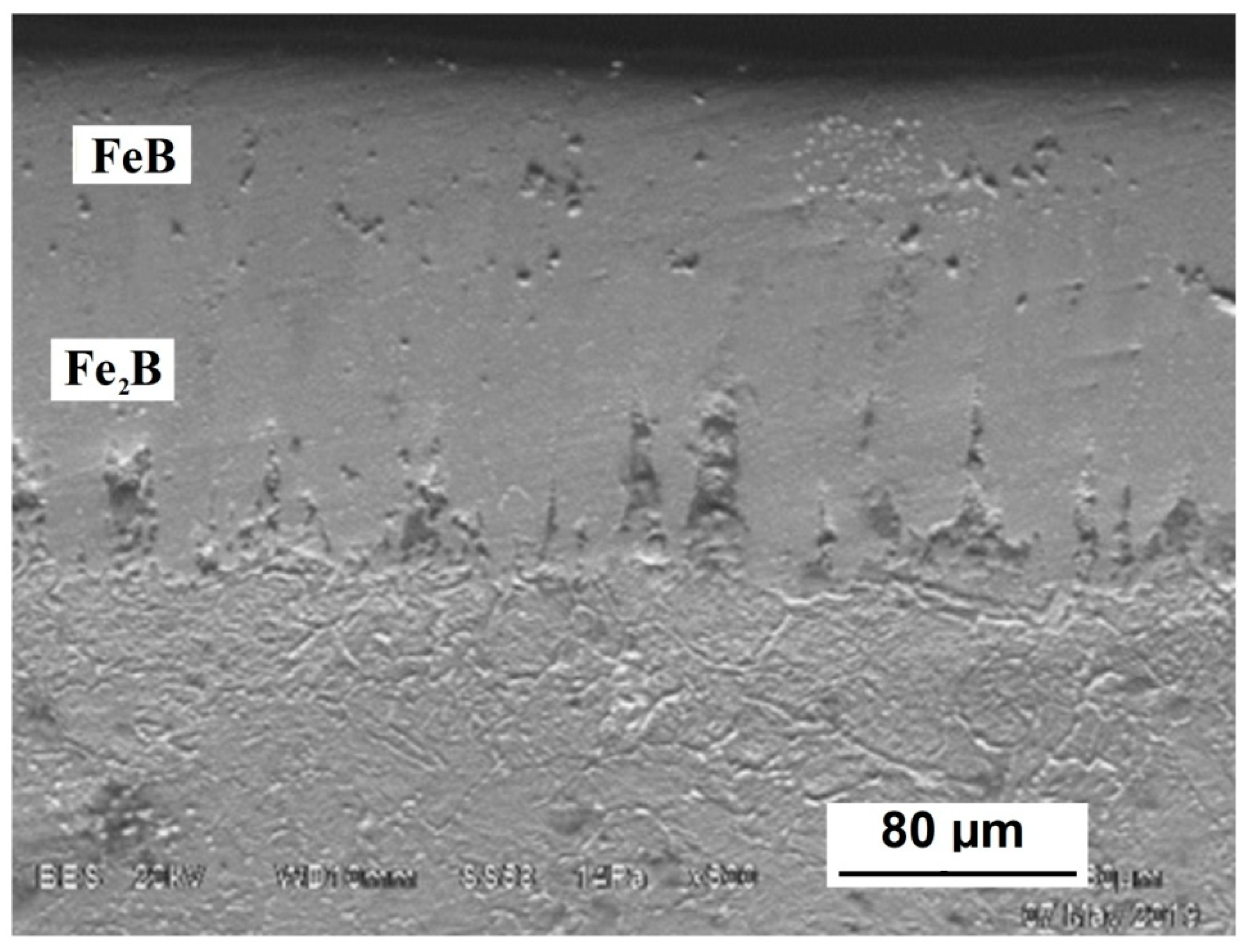
| Phase composition | FeB/Fe2B | FeB/Fe2B | FeB/Fe2B |
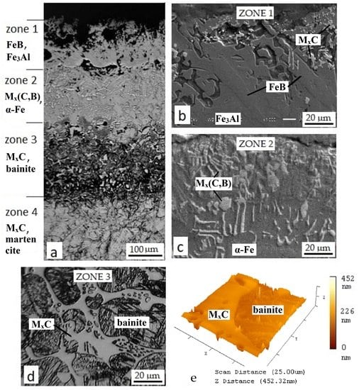
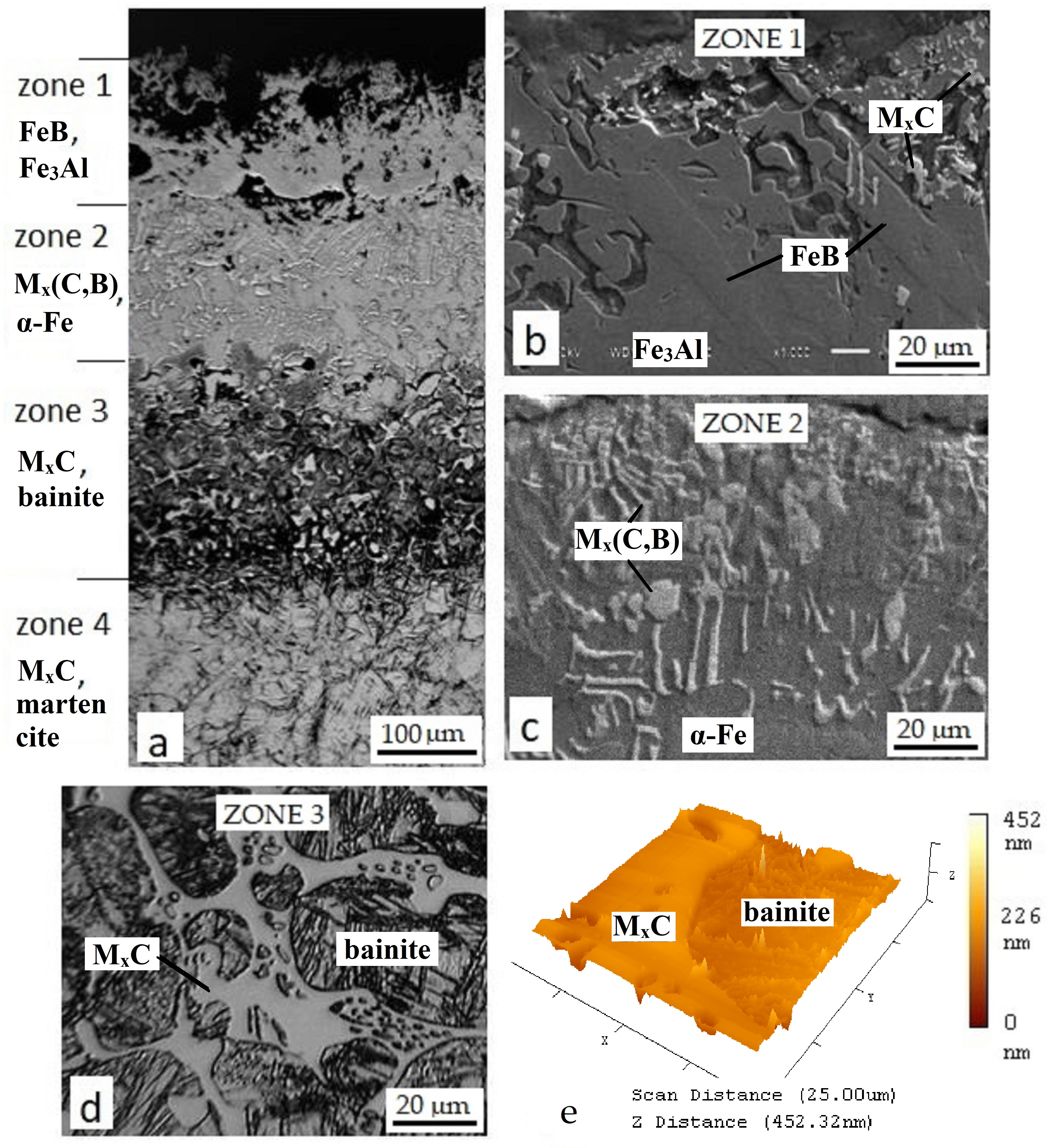
| Distance from the Surface | Probable Phase Composition | B 1 | Al | C 1 | V | Cr | Fe | W | Total |
|---|---|---|---|---|---|---|---|---|---|
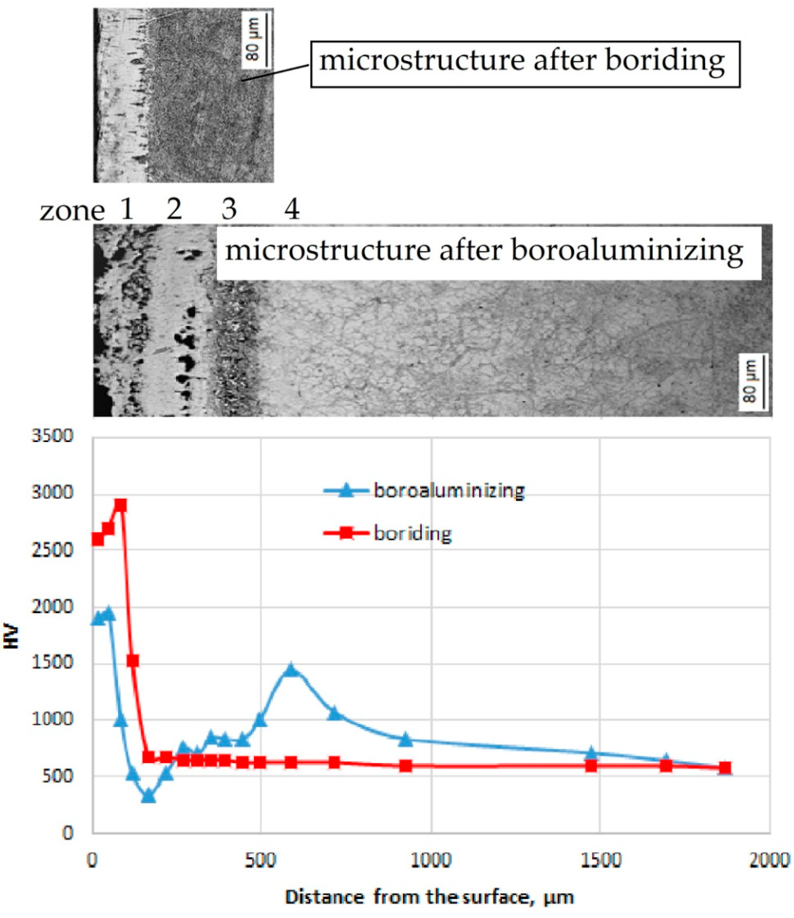
| 25–100 μm (Zone 1) | FeB/Fe3Al | 11.50/- | 0.45/17.50 | 2.93/2.22 | 0.64/- | 4.73/0.63 | 73.00/78.52 | 6.75/1.13 | 100.00/100.00 |
| 175–225 μm (Zone 2) | Mx(B,C)y/α-Fe(C,Al) | 9.84/- | -/10.35 | 8.60/5.71 | 1.42/- | 1.51/0.34 | 22.39/82.08 | 56.24/1.52 | 100.00/100.00 |
| 375–475 μm (Zone 3) | MxC/bainite | -/- | 1.24/5.11 | 7.22/2.92 | 0.69/- | 4.09/- | 76.65/90.46 | 9.73/1.51 | 100.00/100.00 |
| below 560 μm (Zone 4) | MxC+ martensite | - | - | 7.90 | 0.48 | 2.50 | 80.04 | 9.08 | 100.00 |
© 2020 by the authors. Licensee MDPI, Basel, Switzerland. This article is an open access article distributed under the terms and conditions of the Creative Commons Attribution (CC BY) license (http://creativecommons.org/licenses/by/4.0/).
Share and Cite
Mishigdorzhiyn, U.; Chen, Y.; Ulakhanov, N.; Liang, H. Microstructure and Wear Behavior of Tungsten Hot-Work Steel after Boriding and Boroaluminizing. Lubricants 2020, 8, 26. https://doi.org/10.3390/lubricants8030026
Mishigdorzhiyn U, Chen Y, Ulakhanov N, Liang H. Microstructure and Wear Behavior of Tungsten Hot-Work Steel after Boriding and Boroaluminizing. Lubricants. 2020; 8(3):26. https://doi.org/10.3390/lubricants8030026
Chicago/Turabian StyleMishigdorzhiyn, Undrakh, Yan Chen, Nikolay Ulakhanov, and Hong Liang. 2020. "Microstructure and Wear Behavior of Tungsten Hot-Work Steel after Boriding and Boroaluminizing" Lubricants 8, no. 3: 26. https://doi.org/10.3390/lubricants8030026
APA StyleMishigdorzhiyn, U., Chen, Y., Ulakhanov, N., & Liang, H. (2020). Microstructure and Wear Behavior of Tungsten Hot-Work Steel after Boriding and Boroaluminizing. Lubricants, 8(3), 26. https://doi.org/10.3390/lubricants8030026