Development of a Model Test System for a Piston Ring/Cylinder Liner-Contact with Focus on Near-to-Application Seizure Behaviour


Abstract
:
1. Introduction
2. Methodical Approach
2.1. Boundary Conditions and Materials
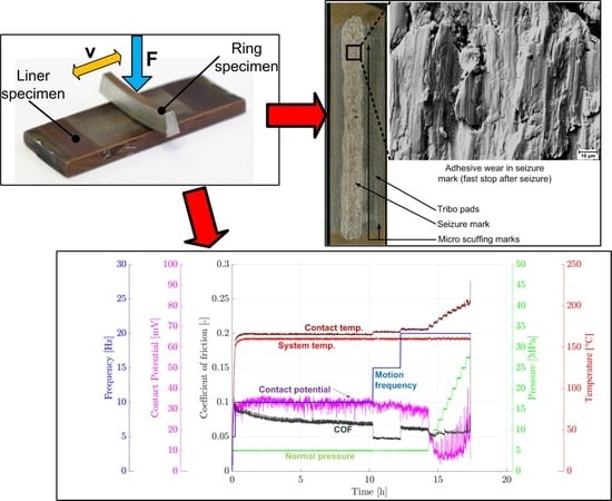
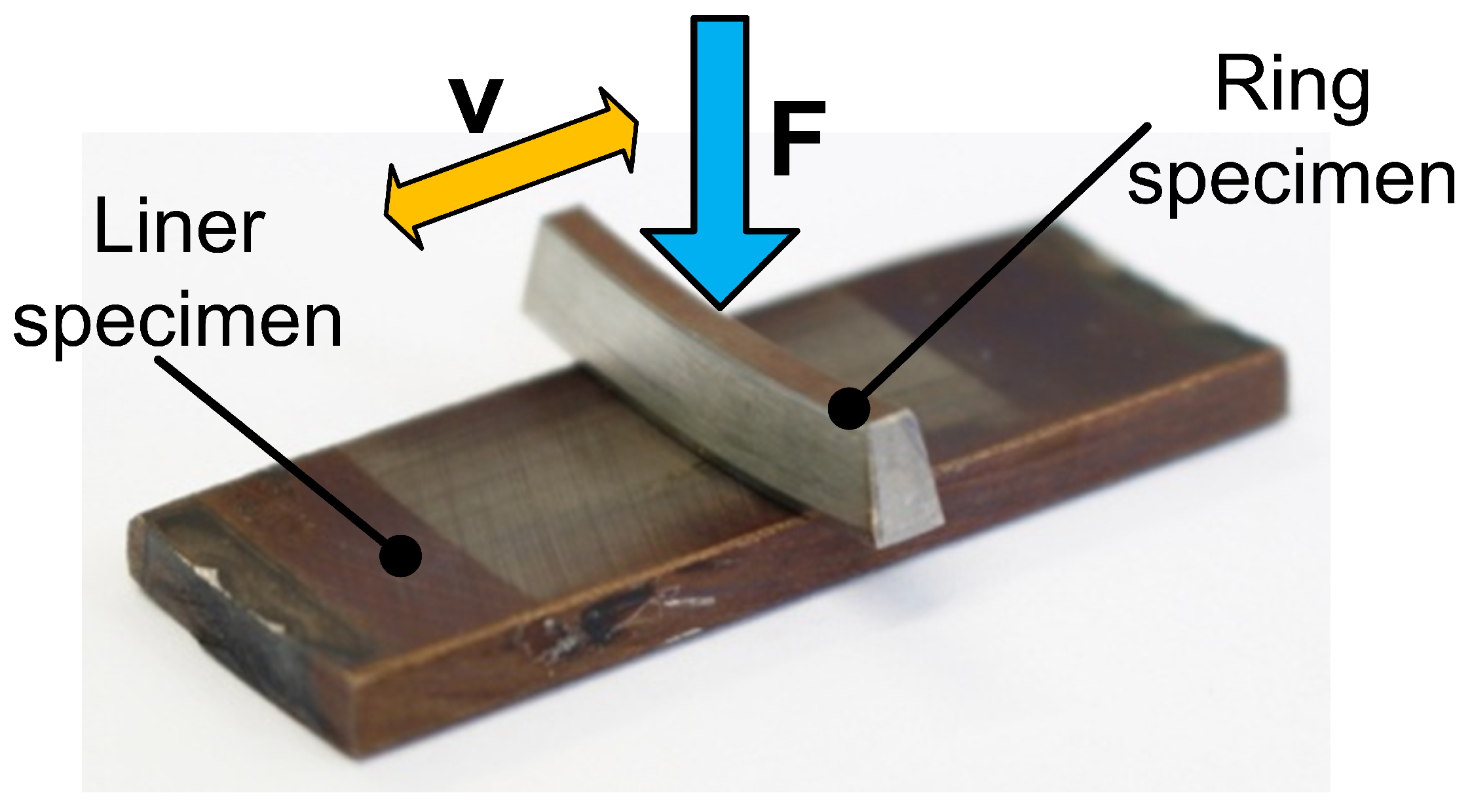
2.2. Test Configuration
2.3. Test Strategy
3. Validation
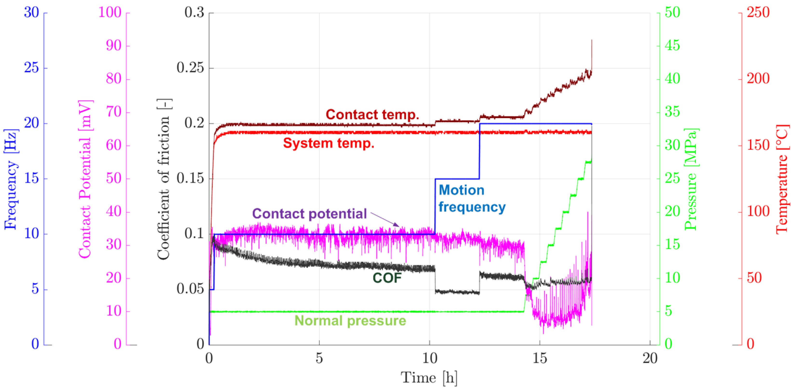
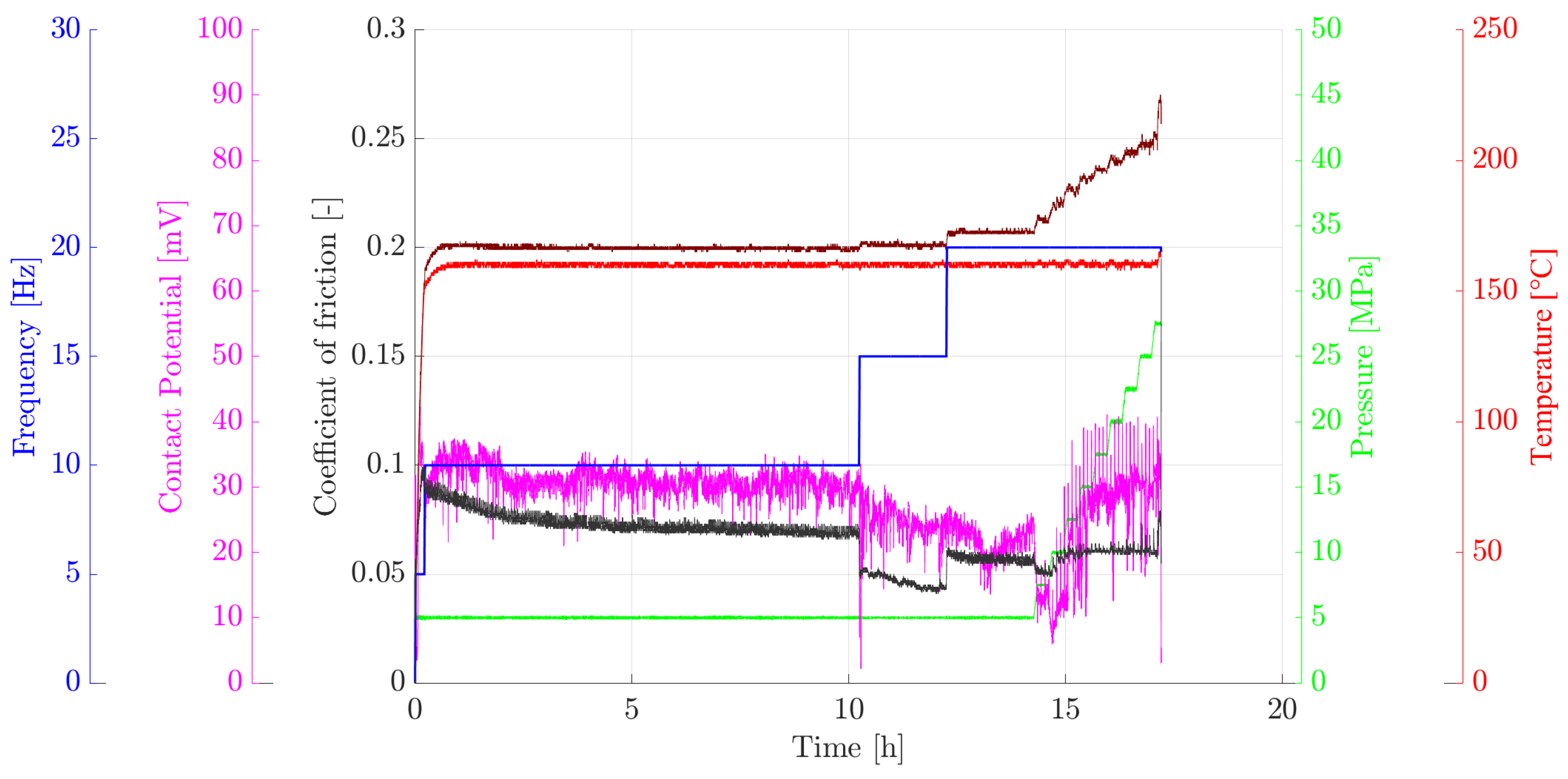
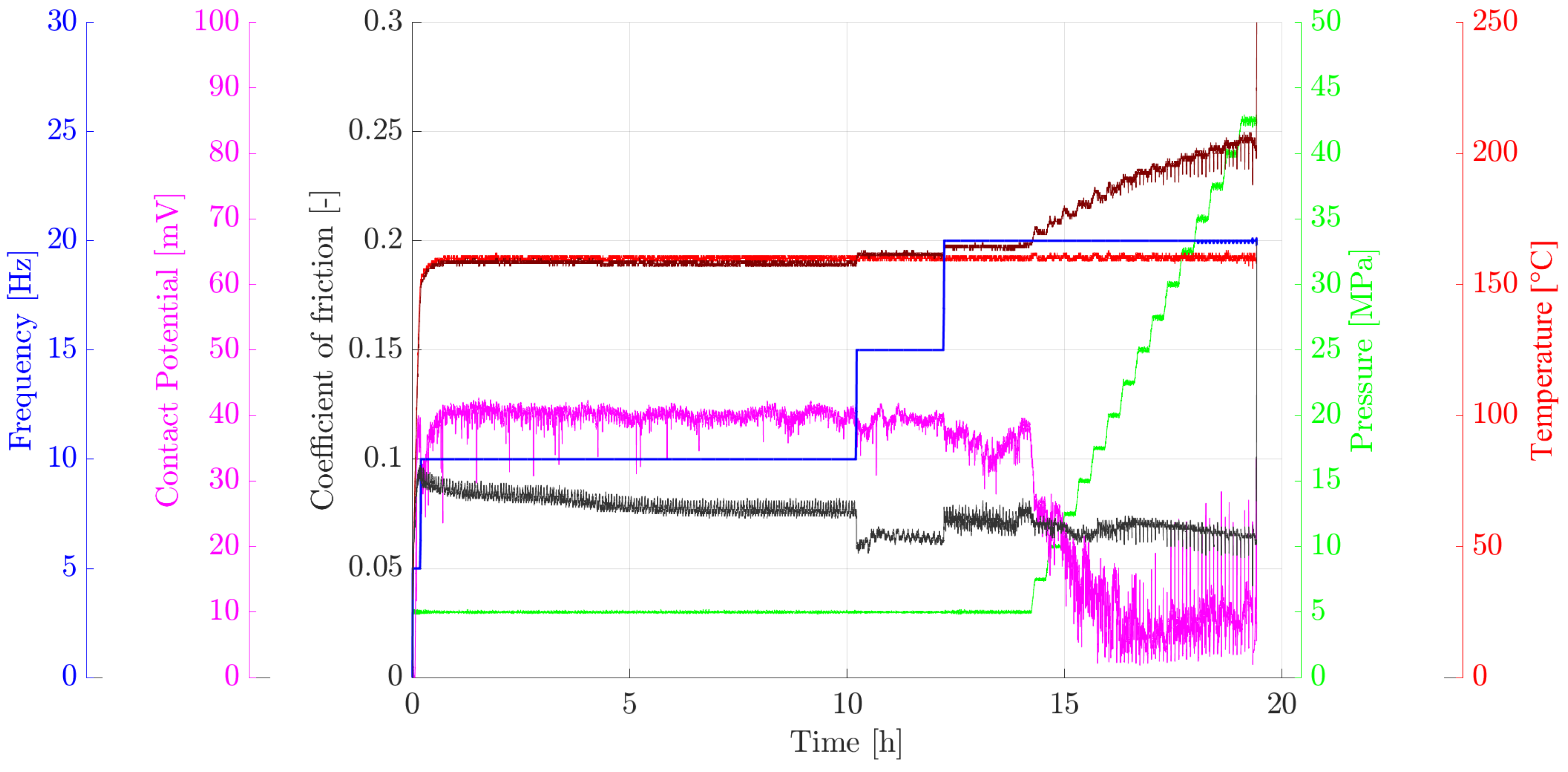
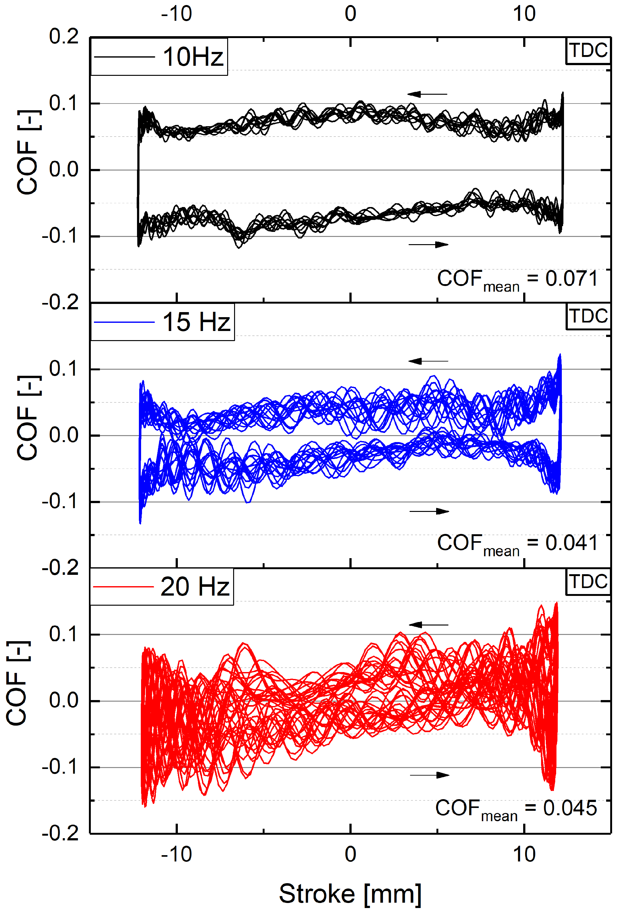
3.1. Test Results
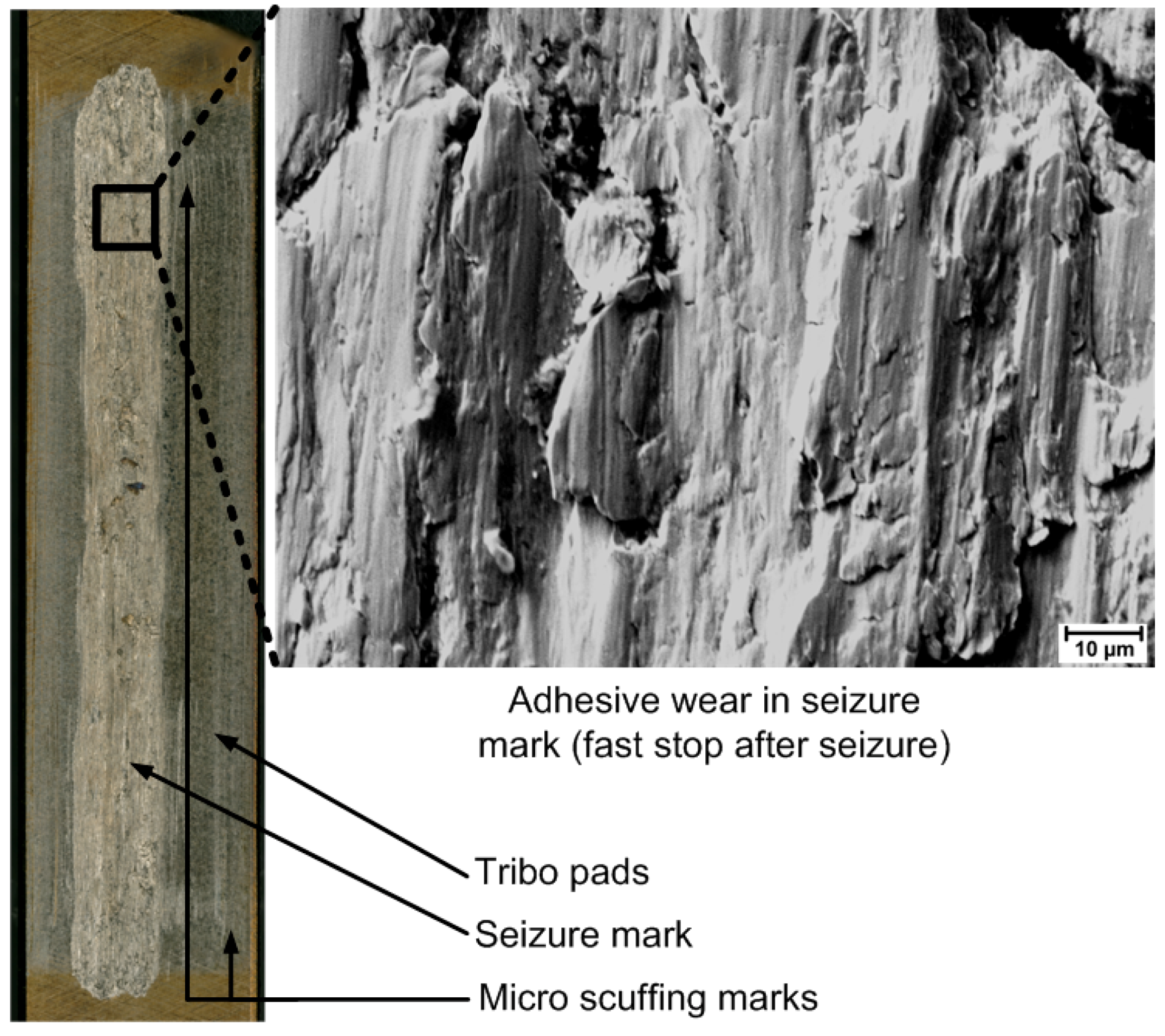
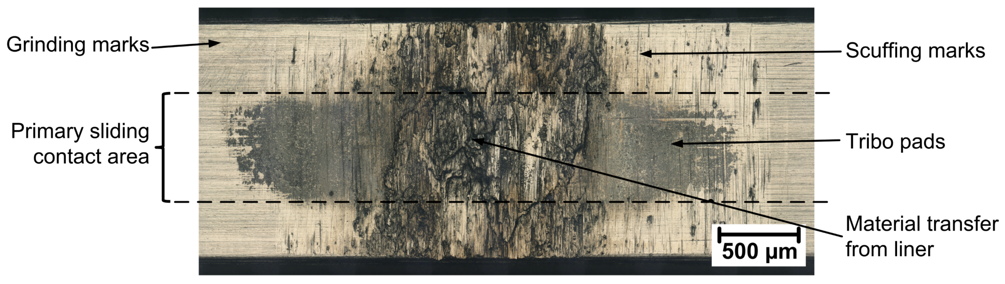
3.2. Surface Analysis
4. Discussion
5. Conclusions
Author Contributions
Funding
Conflicts of Interest
References
- Hackländer, A. Engine Oils for Vehicles—Current Trends and Oil Analysis; Oelcheck Technology Focus: Brannenburg, Germany, 2018; pp. 4–5. [Google Scholar]
- Infineum Insight. How Low Will Viscosity Go? Infineum International Limited: Abingdon, UK, 2012. [Google Scholar]
- Johansson, S.; Nilsson, P.H.; Ohlsson, R.; Rosén, B.G. Experimental friction evaluation of cylinder liner/piston ring contact. Wear 2011, 271, 625–633. [Google Scholar] [CrossRef]
- Grabon, W.; Koszela, W.; Pawlus, P.; Ochwat, S. Improving tribological behaviour of piston ring–cylinder liner frictional pair by liner surface texturing. Tribol. Int. 2013, 61, 102–108. [Google Scholar] [CrossRef]
- Schiffer, J.; Krampl, H.; Godor, I.; Grün, F.; Betz, M.; Laiminger, S. Optimization of the piston ring-cylinder linersystem in gas-engines for power generation. In Proceedings of the 27th CIMAC World Congress on Combustion Engine Technology, Shanghai, China, 13–16 May 2013. [Google Scholar]
- Obert, P.; Müller, T.; Füßer, H.J.; Bartel, D. The influence of oil supply and cylinder liner temperature on friction, wear and scuffing behavior of piston ring cylinder liner contacts—A new model test. Tribol. Int. 2016, 94, 306–314. [Google Scholar] [CrossRef]
- Olander, P.; Jacobson, S. Scuffing resistance testing of piston ring materials for marine two-stroke diesel engines and mapping of the operating mechanisms. Wear 2015, 330–331, 42–48. [Google Scholar] [CrossRef]
- Kamps, T.J.; Walker, J.C.; Wood, R.J.; Lee, P.M.; Plint, A.G. Reproducing automotive engine scuffing using a lubricated reciprocating contact. Wear 2015, 332–333, 1193–1199. [Google Scholar] [CrossRef]
- Keller, J.; Fridrici, V.; Kapsa, P.; Huard, J.F. Surface topography and tribology of cast iron in boundary lubrication. Tribol. Int. 2009, 42, 1011–1018. [Google Scholar] [CrossRef]
- Pusterhofer, M.; Summer, F.; Maier, M.; Grün, F. Assessment of shaft surface structures on the tribological behavior of journal bearings by physical and virtual simulation. Lubricants 2019. submitted. [Google Scholar]
- Grabon, W.; Pawlus, P.; Sep, J. Tribological characteristics of one-process and two-process cylinder liner honed surfaces under reciprocating sliding conditions. Tribol. Int. 2010, 43, 1882–1892. [Google Scholar] [CrossRef]
- Liu, K.; Liu, X.J.; Gui, C.L. Scuffing failure analysis and experimental simulation of piston ring–cylinder liner. Tribol. Lett. 1998, 5, 309–312. [Google Scholar] [CrossRef]
- Shuster, M.; Combs, D.; Karrip, K.; Burke, D. Piston Ring Cylinder Liner Scuffing Phenomenon Studies Using Acoustic Emission Technique; SAE International: Warrendale, PA, USA, 2000. [Google Scholar]
- Söderfjäll, M.; Herbst, H.M.; Larsson, R.; Almqvist, A. Influence on friction from piston ring design, cylinder liner roughness and lubricant properties. Tribol. Int. 2017, 116, 272–284. [Google Scholar] [CrossRef]
- Wopelka, T.; Cihak-Bayr, U.; Lenauer, C.; Ditrói, F.; Takács, S.; Sequard-Base, J.; Jech, M. Wear of different material pairings for the cylinder liner-piston ring contact. Ind. Lubr. Tribol. 2018, 70, 687–699. [Google Scholar] [CrossRef]
- Olander, P.; Eskildsen, S.S.; Fogh, J.W.; Hollman, P.; Jacobson, S. Testing scuffing resistance of materials for marine 2-stroke engines—Difficulties with lab scale testing of a complex phenomenon. Wear 2015, 340–341, 9–18. [Google Scholar] [CrossRef]
- Truhan, J.J.; Qu, J.; Blau, P.J. A rig test to measure friction and wear of heavy duty diesel engine piston rings and cylinder liners using realistic lubricants. Tribol. Int. 2005, 38, 211–218. [Google Scholar] [CrossRef]
- Biberger, J.; Füßer, H.J. Development of a test method for a realistic, single parameter-dependent analysis of piston ring versus cylinder liner contacts with a rotational tribometer. Tribol. Int. 2017, 113, 111–124. [Google Scholar] [CrossRef]
- Neale, M.J. Piston ring scuffing—A broad survey of problems and practice. Proc. Inst. Mech. Eng. 1970, 21–32. [Google Scholar] [CrossRef]
- Balyts’kyi, O.I.; Abramek, K.F.; Shtoeck, T.; Osipowicz, T. Diagnostics of Degradation of the Lock of a Sealing Ring According to the Loss of Working Gases of an Internal Combustion Engine. Mater. Sci. 2014, 50, 156–159. [Google Scholar] [CrossRef]
- Balyts’kyi, O.I.; Abramek, K.F.; Mruzik, M.; Stoeck, T.; Osipowicz, T. Evaluation of the Losses of Hydrogen-Containing Gases in the Process of Wear of Pistons of an Internal-Combustion Engine. Mater. Sci. 2017, 53, 289–294. [Google Scholar] [CrossRef]
- MAHLE GmbH (Ed.) Kolben und Motorische Erprobung, 2nd ed.; Springer: Wiesbaden, Germany, 2015. [Google Scholar]
- Zima, S. Motorkolben: Bauarten, Betrieb, Schäden, 1st ed.; Vieweg & Sohn Verlag: Wiesbaden, Germany, 2005. [Google Scholar]
- van Basshuysen, R.; Schäfer, F. (Eds.) Handbuch Verbrennungsmotor: Grundlagen, Komponenten, Systeme, Perspektiven, 8th ed.; Springer: Wiesbaden, Germany, 2017. [Google Scholar]
- Salehi, R.; Stefanopoulou, A. Cylinder Pressure Data from a Heavy Duty Diesel Engine; University of Michigan: Ann Arbor, MI, USA, 2015. [Google Scholar]
- Schiffer, J.; Gódor, I.; Grün, F.; Eichlseder, W. A Model Scale Test Method for the Piston Ring—Cylinder Liner Tribosystem of Internal Combustion Engines. Arch. Mech. Eng. 2010, 57, 211. [Google Scholar] [CrossRef]
- Summer, F.; Grün, F.; Schiffer, J.; Gódor, I.; Papadimitriou, I. Tribological study of crankshaft bearing systems: Comparison of forged steel and cast iron counterparts under start–stop operation. Wear 2015, 338–339, 232–241. [Google Scholar] [CrossRef]
- Galligan, J.; Torrance, A.A.; Liraut, G. A scuffing test for piston ring/bore combinations: Pt. II. Formulated motor lubrication. Wear 1999, 236, 210–220. [Google Scholar] [CrossRef]
- Kontou, A.; Southby, M.; Spikes, H.A. Effect of steel hardness on soot wear. Wear 2017, 390–391, 236–245. [Google Scholar] [CrossRef]
- Motamen Salehi, F.; Morina, A.; Neville, A. The effect of soot and diesel contamination on wear and friction of engine oil pump. Tribol. Int. 2017, 115, 285–296. [Google Scholar] [CrossRef]
- Greuter, E.; Zima, S. Motorschäden: Schäden an Verbrennungsmotoren und Deren Ursachen; Vogel: Würzburg, Germany, 2000. [Google Scholar]
- Shuster, M.; Stong, T.; Deis, M.; Burke, D. Piston Ring Cylinder Liner Scuffing Phenomenon: Investigation, Simulation and Prevention; SAE Technical Paper; SAE International: Warrendale, PA, USA, 1999. [Google Scholar]
- Kamps, T.J.; Walker, J.C.; Wood, R.J.; Lee, P.M.; Plint, A.G. Scuffing mechanisms of EN-GJS 400-15 spheroidal graphite cast iron against a 52100 bearing steel in a PAO lubricated reciprocating contact. Wear 2017, 376–377, 1542–1551. [Google Scholar] [CrossRef]
- Tas, M.O.; Banerji, A.; Lou, M.; Lukitsch, M.J.; Alpas, A.T. Roles of mirror-like surface finish and DLC coated piston rings on increasing scuffing resistance of cast iron cylinder liners. Wear 2017, 376–377, 1558–1569. [Google Scholar] [CrossRef]
- Saeidi, F.; Taylor, A.A.; Meylan, B.; Hoffmann, P.; Wasmer, K. Origin of scuffing in grey cast iron-steel tribo-system. Mater. Des. 2017, 116, 622–630. [Google Scholar] [CrossRef]


| Component/Parameter | Used in Application | Used in Model |
|---|---|---|
| Liner | Honed grey cast iron | Original |
| Piston ring | Coated chromium-steel | Original with coating removed |
| Lubricant | Fully formulated engine oils | Original engine oils |
| Lubrication | Deficient (due to oil scaper ring) | Min. drop lubrication (0.04 mL/min) |
| Relative velocity | Max. 5–15 m/s according to [24] | Max. 1.5 m/s |
| Temperature | 200–300 C at top piston groove [22] | 160 C system temperature |
| Contact pressure | 17 MPa peak according to [25] | 5 MPa constant for running-in |
| Test-ID | Liner Weight Change (mg) | Ring Weight Change (mg) |
|---|---|---|
| “Oil 1”, Test Nr. 1 | 0.73 | |
| “Oil 1”, Test Nr. 2 | 0.67 | |
| “Oil 2”, Test Nr. 1 | 1.20 |
© 2019 by the authors. Licensee MDPI, Basel, Switzerland. This article is an open access article distributed under the terms and conditions of the Creative Commons Attribution (CC BY) license (http://creativecommons.org/licenses/by/4.0/).
Share and Cite
Pusterhofer, M.; Summer, F.; Wuketich, D.; Grün, F. Development of a Model Test System for a Piston Ring/Cylinder Liner-Contact with Focus on Near-to-Application Seizure Behaviour. Lubricants 2019, 7, 104. https://doi.org/10.3390/lubricants7120104
Pusterhofer M, Summer F, Wuketich D, Grün F. Development of a Model Test System for a Piston Ring/Cylinder Liner-Contact with Focus on Near-to-Application Seizure Behaviour. Lubricants. 2019; 7(12):104. https://doi.org/10.3390/lubricants7120104
Chicago/Turabian StylePusterhofer, Michael, Florian Summer, Daniel Wuketich, and Florian Grün. 2019. "Development of a Model Test System for a Piston Ring/Cylinder Liner-Contact with Focus on Near-to-Application Seizure Behaviour" Lubricants 7, no. 12: 104. https://doi.org/10.3390/lubricants7120104
APA StylePusterhofer, M., Summer, F., Wuketich, D., & Grün, F. (2019). Development of a Model Test System for a Piston Ring/Cylinder Liner-Contact with Focus on Near-to-Application Seizure Behaviour. Lubricants, 7(12), 104. https://doi.org/10.3390/lubricants7120104