Article

An Experimental Study on Starved Grease Lubricated Contacts

by
David E. P. Gonçalves
1,*,
Armando V. Campos
2 and
Jorge H. O. Seabra
3
1
INEGI, Universidade do Porto, Rua Dr. Roberto Frias s/n, 4200-465 Porto, Portugal
2
ISEP-IPP, Instituto Superior de Engenharia do Porto, 4200-072 Porto, Portugal
3
FEUP, Faculdade de Engenharia da Universidade do Porto, Rua Dr. Roberto Frias s/n, 4200-465 Porto, Portugal
*
Author to whom correspondence should be addressed.
Lubricants 2018, 6(3), 82; https://doi.org/10.3390/lubricants6030082
Submission received: 17 July 2018 / Revised: 27 August 2018 / Accepted: 6 September 2018 / Published: 10 September 2018
(This article belongs to the Special Issue Advances in Polymer Tribology)

Abstract

:
The film thickness of a ball-on-disc contact lubricated with four greases of different formulations was measured under different operating conditions until starvation. Two polymer-thickened greases and two lithium-thickened greases, formulated with base oils of different nature and/or viscosity, were tested. The central film thickness was measured under constant operating conditions (load, temperature, slide-to-roll ratio) varying only the entrainment speed. In a separate test, the film thickness was measured over time with all operating conditions set to constant. Pictures of the film thickness profile across the contact area were also registered. The results were compared with the fully flooded results. The coefficient of friction (COF) was measured in a ball-on-disc contact under equal operating conditions and the results were correlated with the film thickness findings. The different grease formulations and the influence of the operating conditions on the film thickness and COF were discussed. The polymer thickened the greases, promoting lower COF and higher film thickness, especially when there is thickener material crossing the contact which happens quite often for these greases.

1. Introduction

Starvation in oil lubricated contacts was first visually observed using optical interferometry by Wedeven et al. [1] in 1971, followed by Chiu et al. [2], and later, by Pemberton and Cameron [3]. Wedeven et al. [1] observed that if the inlet region is properly flooded with lubricant, the inlet pressure build-up will generate a lubricant film whose thickness will no longer increase even if the lubricant supply increases—the fully flooded condition [1]. However, if there is no replenishment, or if the inlet region is insufficiently filled, a lubricant-air meniscus is formed at the contact inlet when the lubricant layers from the rolling element and raceway merge [4,5]. The pressure build-up is delayed and the film is restricted and dependent on the lubricant supply available at the inlet. This phenomenon not only severely reduces the film thickness, but as the contact gets further starved, the pressure spike close to the outlet gets smaller up to the point where the pressure build-up resembles an Hertzian dry-contact [4]. As the contact starves, the central film thickness approaches the minimum film thickness, and the load caring capacity is decreased. This condition where an increase in the lubricant supply results in increased film thickness is called starvation.
The film thickness and friction tests are generally performed under the assumption that the contact is fully flooded. This condition is ensured using a scoop that continuously feeds the contact with grease by forcing it back into the contact track. However, if no scoop is used, the lubricant supply continually decreases with successive over-rollings because the grease is pushed to the sides [4,6]. Even though starvation can also happen in oil lubricated contacts, it is much more frequent in grease lubrication mainly because of the very high viscosity of the grease at low temperatures and low shear and consequently, its low mobility [4,6,7].
Aihara and Dowson [8] performed an experimental study in a two-disc machine, suggesting that the grease’s film thickness under starvation was about 70% of the fully flooded film thickness of the base oil. Kauzlarich and Greenwood pointed out that shear degradation of the grease leads to a reduction of the film thickness with time [9]. Later, Aström et al. [10] found that the grease’s yield stress ( τ y ) and/or high viscosity at low shear rates is responsible for slower contact replenishment. The authors also claimed that spin helps to transport the grease from the side bands to the inlet, contributing to better replenishment.
Cann et al. [7] performed film thickness measurements over time under constant operating conditions and observed that the degree of starvation (ratio between the starved and the fully flooded film thickness) increases with rolling speed, base oil viscosity and thickener content, but it decreases with temperature. The thickener content affects the grease consistency, and a starved film thickness plateau is reached sooner for greases with higher thickener content. Furthermore, they also found that a higher thickener content also slows the oil bleeding, restricting the film build-up. Increasing the base oil viscosity also increases the degree of starvation which might also be related to the smaller oil bleeding that it promotes [11]. On the other hand, the temperature increase and the consequent decrease in consistency improve the replenishment which should improve the oil bleeding and consequently, should reduce the degree of starvation [12].
Using optical interferometry to visually determine when starvation occurs in a ball-on-disc contact, Kaneta et al. [13] found that starvation takes place quicker (meaning, at lower entrainments speeds but also in smaller time of operation) with greases formulated with high viscosity oils. They also found that starvation occurs more easily with higher speeds because the time for replenishment between over-rollings is shorter, hindering replenishment. More recently, Chen et al. [6] performed film thickness measurements over increasing speeds in a ball-on-disc device and found that starvation occurs at smaller speeds with greases formulated with base oils of smaller viscosity, contradicting what was expected for oil lubrication where smaller viscosity oils show better replenishment.
Mérieux et al. defined the most common behaviours in starved grease lubrication [14]. Generally, the film thickness decreases with time as the contact gets depleted from lubricant, quickly dropping from the fully flooded value. From here, the film thickness may continually drop or eventually stabilize. Quite often, it is also possible that replenishment is recovered and the film thickness may rise again.
According to Cann et al. [15], the stabilized layer (residual layer) is composed by a liquid layer of base oil on top of a solid-like, thickener-rich layer. This solid-like layer is measured at the end of the test at zero speed and shows thickness values between 6 nm and 80 nm [15]. Venner et al. [16] developed a thin-layer flow model model to predict such behaviour while using the base oil viscosity as the input and setting the thickener layer thickness to the level corresponding to the zero-speed test. This result can be found in Ref. [17] introducing new lines of research to studying thickener–additives–surface interactions and their characteristics when thick boundary layers are formed.
In spite of the fact that some grease lubricated rolling bearings operate under fully flooded conditions, the large majority operates under starvation. To achieve the fully flooded condition, it would be necessary to continuously supply a flow of grease to the rolling bearing which is generally undesirable since it promotes high torque and excessive churning, resulting in high operating temperatures and ultimately, failure [7]. Therefore, under normal operating conditions and depending on the initial grease volume and distribution, the contacts will eventually starve due to side flow, centrifugal effects, and/or gravity, cage scraping, surface tension, air flow, or oil bleeding from grease and evaporation [4,11]. Hence, the study of grease lubricated contacts is of utmost importance for rolling bearing technology.

2. Methods and Materials

2.1. Tested Greases

The tested greases’ main properties are shown in Table 1. The grease samples M2, M5, MLi, and MLiM were experimentally designed for this work and were manufactured by Axel Christiernsson, a grease manufacturing company from Sweden.
The M2 and M5 greases were formulated with a poly-alpha-olefin (PAO) base oil and thickened with polypropylene (PP), a polymer used here as a thickener.
The MLi grease was formulated with a mixture of two different grades of PAO and 5% ester (PAO + 5%E) added to facilitate the saponification reaction. Finally, thee MLiM grease was formulated with a base oil of mineral (MIN) nature. Both MLi and MLiM were formulated with Lithium Complex (LiX) soap thickener.
None of these greases were additized. However, greases M5 and MLiM were formulated with an elastomer (as a co-thickener), which works as a viscosity improver of the oil bled by the grease under work [18]. For more information regarding the polymer thickened greases, please refer to Refs. [19,20,21,22].
Samples of each grease were prepared for microstructural characterization using Atomic Force Microscopy (AFM) by carefully scraping the grease on a steel disk. AFM measurements were taken using a Multimode AFM (Veeco Metrology, Santa Barbara, CA, USA) with a Nanoscope IVA controller. Tapping mode AFM images were collected with commercially available silicon cantilevers (Bruker TESP-SS, Waltham, MA, USA). These super sharp silicon cantilevers (tip size: 2 nm) had to be used because of the very high adhesion and viscosity of the oil on the surface of the grease. These special tips get ruined very often, for the same reason. The measuring process is also very difficult since it is common to find a lot of oil on the surface, while the embedded thickener elements are below the surface and, therefore, it is very hard for the tip to interact with them.
The resulting 2D images (5 μ m × 5 μ m) of the topography of greases M2, M5, MLi, and MLiM are shown in Figure 1. At least two pictures were taken in different areas of the same sample to ensure that each picture was representative of the sample’s surface. For each measurement, the system scanned the surface in two different directions, but only the one that showed the smaller amount of artefacts is presented here.
It was confirmed that both LiX thickener greases include twisted fibres entangled with each other. The volume fraction of fibres was shown to be higher for grease MLi, although the fibres were thinner than grease MLiM. On the other hand, the structure of the thickener in grease MLiM grease was coarser than that of MLi. The average diameter of the fibres was similar to what was found in the pictures from SEM [23]. It was also not possible to infer the fibres’ lengths, since it is clearly impossible to identify the beginning and ending of a single fibre embedded in the oil. Regarding the polymer greases, it was even harder to conclude anything. Although the results of grease M2 look very different from those of grease M5, its structure should, in fact, be very similar with particle-like elements [23]. However, for grease M2, it was very hard to reach a zone where thickener material was close to the surface, and even when it was, its morphology was very hard to understand.

2.2. Measurement Procedure

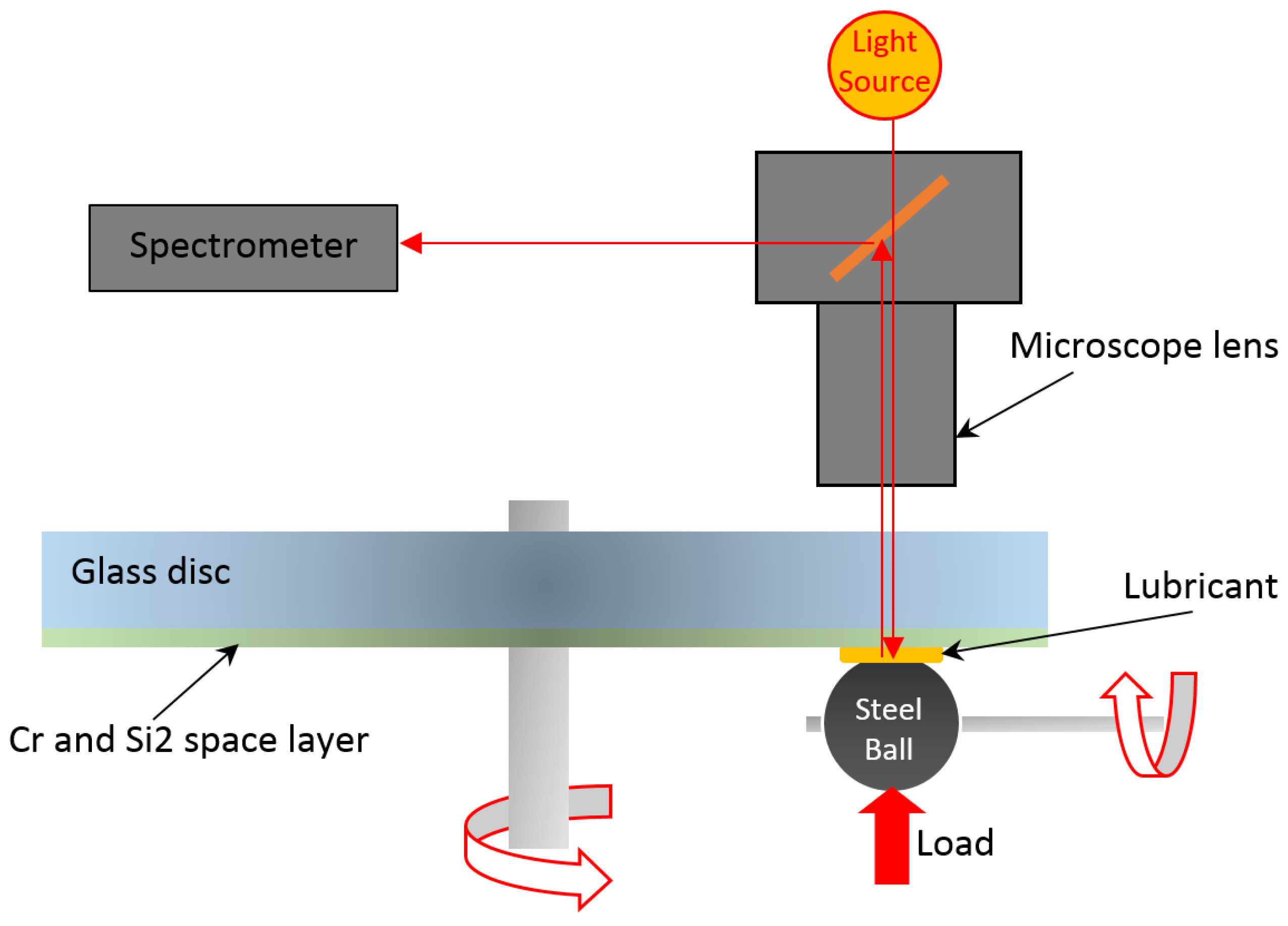
2.2.1. Film Thickness

To evaluate the lubricant film thickness in a ball-on-disc contact, the interferometry technique was used. Produced by PCS Instruments (UK), the EHD2 device is capable of measuring the lubricant film thickness in a ball-on-disc or roller-on-disc configuration for thin films (1 nm resolution up to 1000 nm). This device is capable of controlling the lubricant temperature, ball and disc entrainment speeds, contact load, and slide-to-roll ratio (SRR).
A schematic of the measuring system and interferometry method is shown in Figure 2. A light source projects light into the contact between the ball and the disc through a microscope lens. Part of this light is reflected from the underside of the glass disc and some passes through any lubricant film and is then reflected back from the steel ball. The fact that the two light beams have travelled different lengths causes interference fringes captured by the spectrometer. The central film thickness is then computed from the interference fringes with high precision.
Three different tests were performed to evaluate the evolution of film thickness over time:
(1)
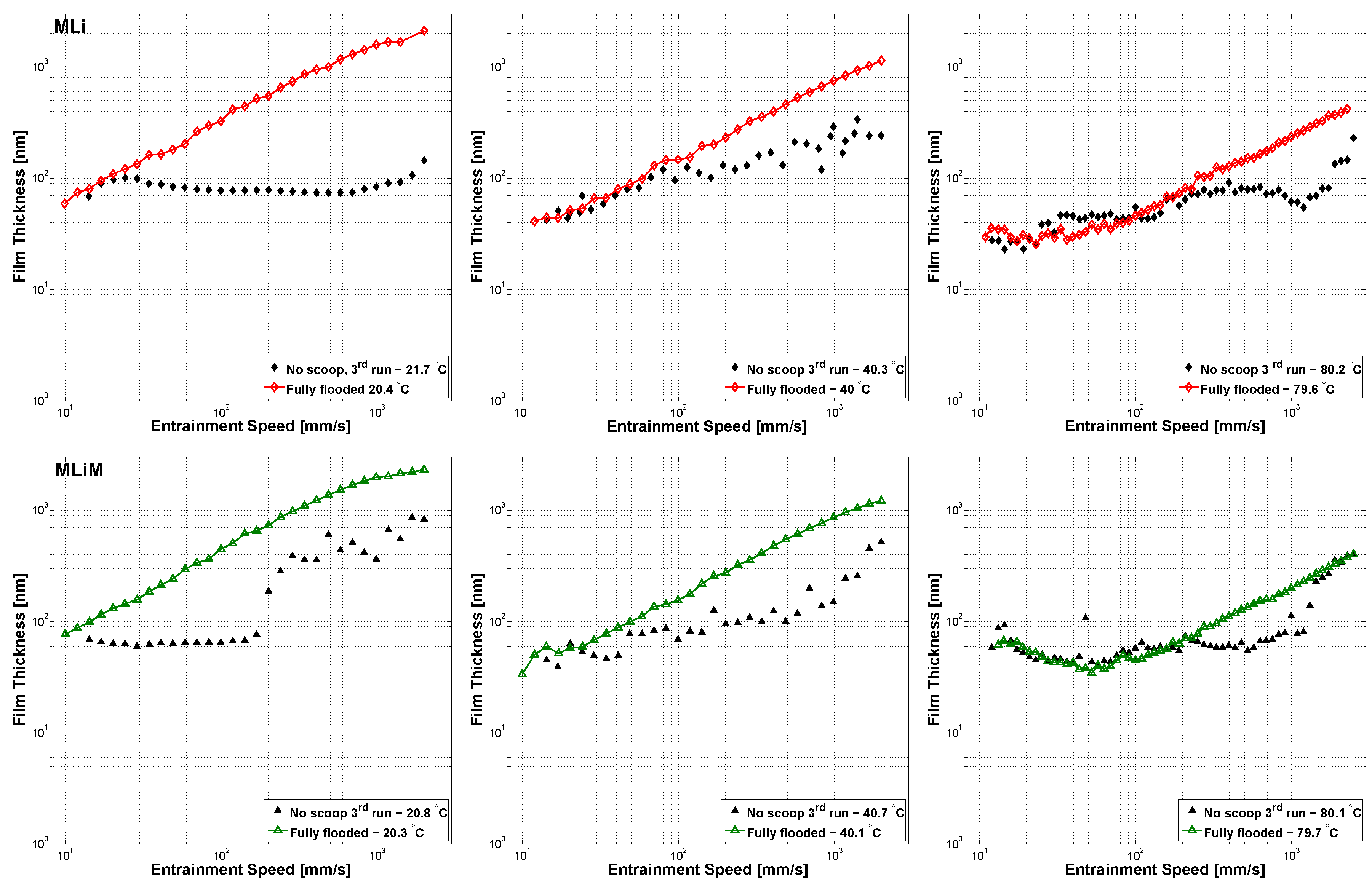
Central film thickness, varying the entrainment speed;
(2)
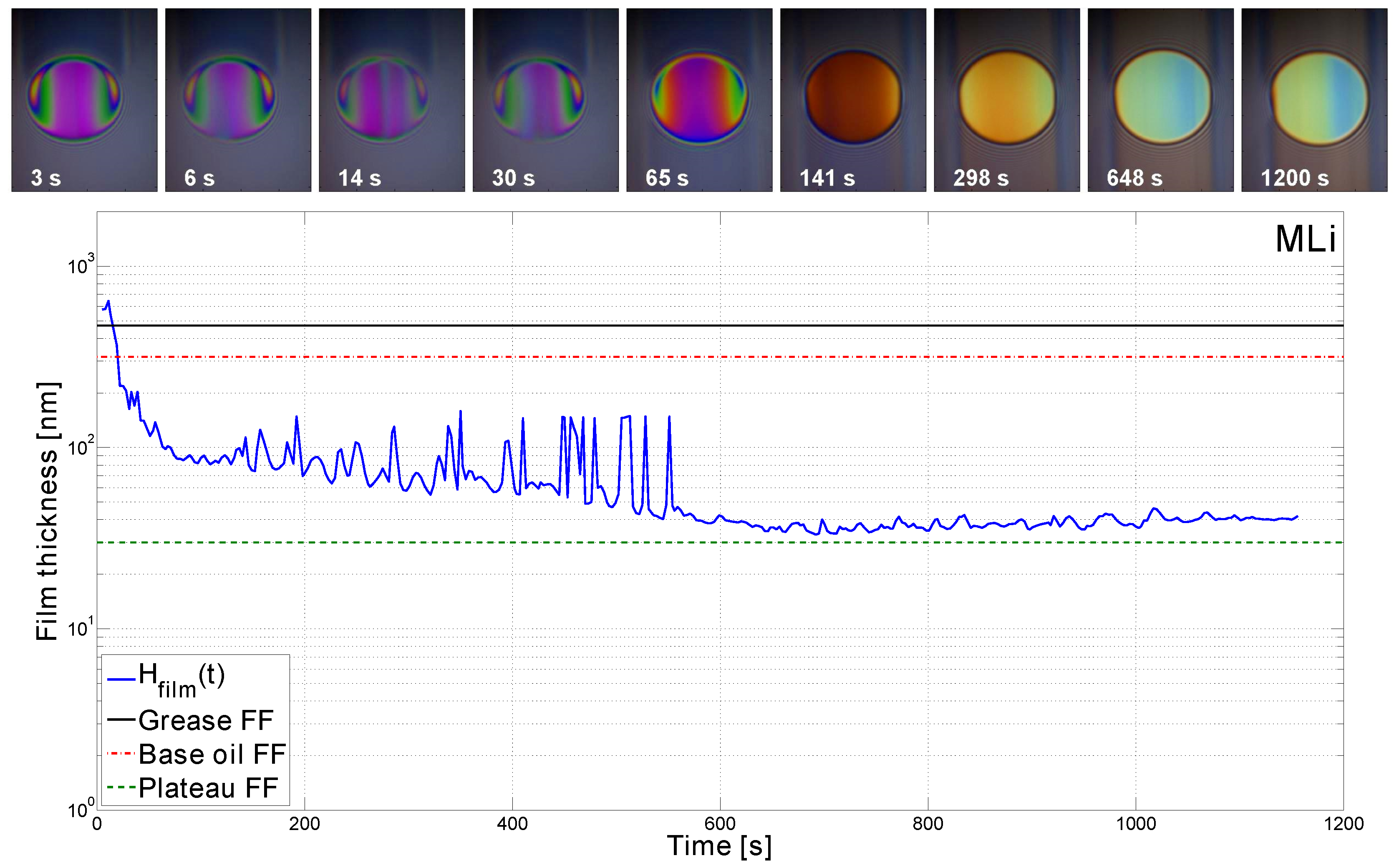
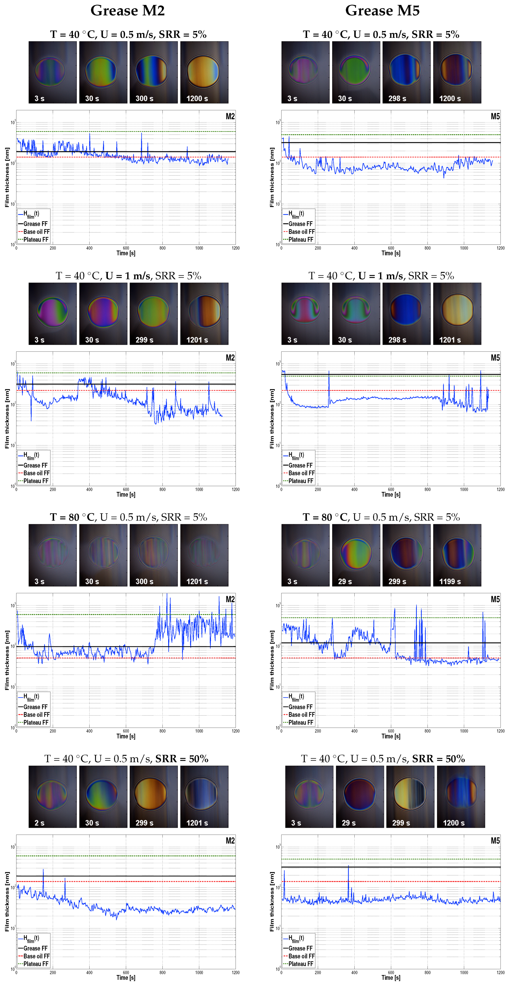
Central film thickness, measured over time;
(3)
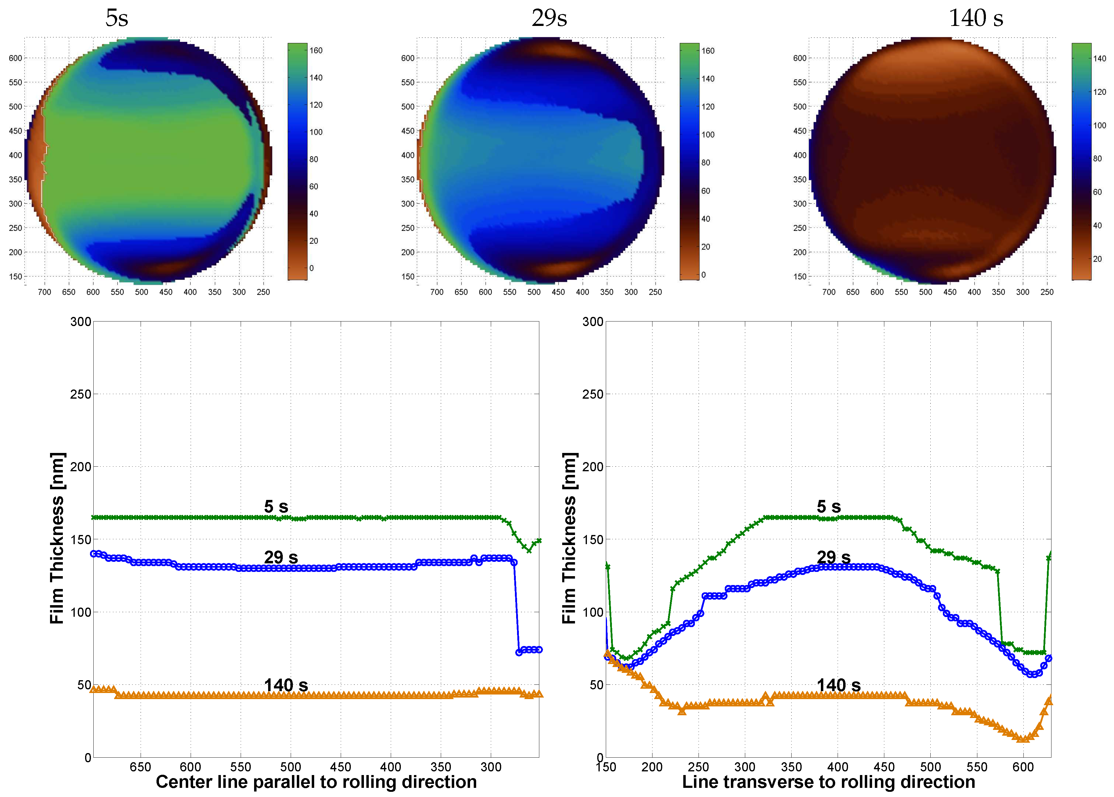
Film thickness profile pictures across the contact area, measured over time.
Before each test, a heat period of 30 min was applied to ensure temperature stabilization. The space layer thickness was measured at the disc track radius, at zero speed, and without any lubricant between the ball and the disc. The space layer thickener is important for the precise evaluation of the film thickness. The specimens used for the ball and glass disc are stated in Table 2. In all three tests, all operating conditions were set to be constant, except for the time or entrainment speed.
In the first test type, three speed ramps were performed at a constant load, temperature, and slide-to-roll ratio (SRR). The ball-on-disc device used in this work does not allow the scoop to be removed during the actual test and therefore, no scoop was used right from the beginning. Since the lubricant supply should change with each ramp, the average of three measurements was not calculated. However, given that the ramps were performed from low to high speeds, the first ramp should be representative of the fully flooded result. The entrainment speed (U 0 ) ramps were performed from 10 mm/s to 2 m/s, controlling the temperature (T) at 20, 40, and 80 C. The normal load (F) was set constant at 50 N and the SRR was set to 5%. Each speed ramp took about 180 s with a delay of less than 10 s between ramps.
In the second test type, the central film thickness was measured for each grease under the conditions stated in Table 3. Test number 1 was used as a reference, while the other tests were performed after only changing one of the conditions each time. At the end of each test, a zero speed thickness was also measured. The test time was 1200 s, since it was frequent for the disc track to show damage after this time for some of the tests, and therefore, the film thickness results were unreliable from this point onwards.
Finally, in the third test type, the same operating conditions as those shown in Table 3 were used, but instead of using a spectrometer to obtain the monochromatic interference fringes which allows the central film thickness to be calculated, the Space Layer Imaging Method (SLIM) [24] was used. This method uses a sensitive RGB (red, green, blue) colour camera to capture an image of the contact area. The colours of the pixels can be used to calculate the film thickness, producing 3D maps of the film thickness profile across the contact area. These tests were only performed to better understand how the film thickness profile would change along the test duration, but the central film thickness was not computed from the pixel data due to its comparatively lower precision.

2.2.2. Coefficient of Friction

The coefficient of friction was also measured to investigate starvation. Using the same ball-on-disc device and the specimens (ball-on-smooth steel disc) reported in Table 2, the coefficient of friction was measured over time under constant operating conditions. Once again, four different tests were explored, according to the conditions reported in Table 3.

3. Results and Discussion

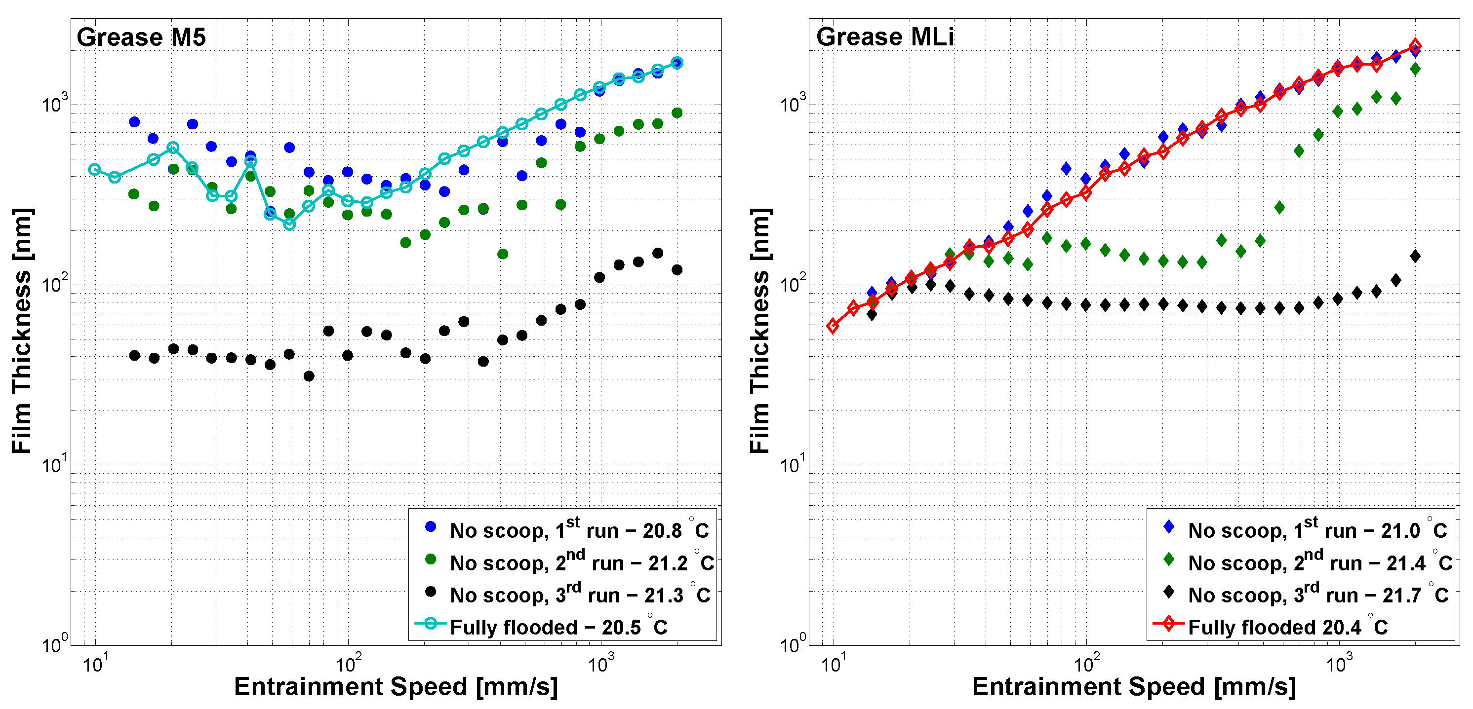
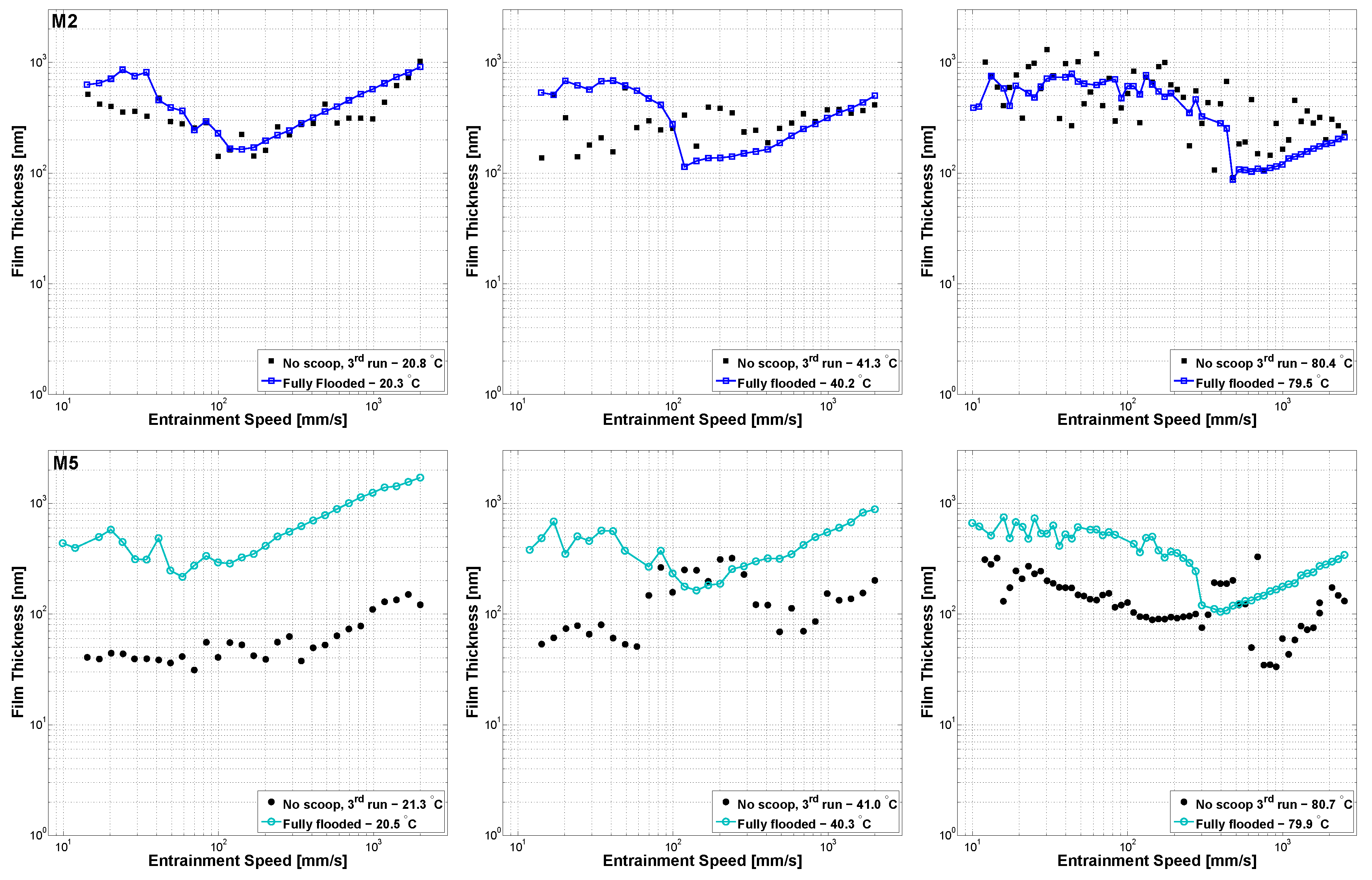
3.1. Central Film Thickness Measured With Varying Entrainment Speed

The central film thickness of the ball-on-disc contact, measured with increasing entrainment speeds at 20 C is shown in Figure 3, for the M5 and MLi greases. The fully flooded result at each temperature measured using the scoop is also shown here for easier comparison.
Generally, under fully flooded conditions, the film thickness under low entrainment speeds shows a “plateau-like” region where the film thickness is almost independent from the entrainment speed, decreasing very slightly with it. This behaviour is attributed to the thickener material crossing the contact, and the scatter can be considerably high in this region. Upon reaching a certain minimum value, the film thickness starts to increase at a slope of U 0.67 , typical of oil lubrication [25,26,27,28,29]. Not all greases show this behaviour under the same temperature or speed range. According to Figure 3, the differences between the first and third speed ramps are very clear, showing that the longer the test duration is, the higher is the deviation from the fully flooded result is. This deviation is attributed to starvation: the lack of scoop causes the contact to gradually starve as the time of the test increases, associated, of course, with the increasing speed (and centrifugal forces) which pushes the grease away from the contact. It is also evident that the lack of scoop greatly increases the scatter of the results, not only in the low speed region, but also in the high speed region. It was also common to measure film thickness values above the fully flooded result for certain speeds. The grease’s chaotic and random behaviour [30] made it hard to measure a representative film thickness for a certain operating condition. It was also difficult to obtain repeatable curves, without the scoop to “control” the replenishment. In the case of the polymer greases, it was even harder, probably due to the increased thickener size [23].
In Figure 4, the central film thickness results are shown for different operating temperatures. In this figure, only the 3rd speed ramp is shown, compared to the fully flooded result. Regarding the effect of increasing speed, it was observed that, generally, there is a speed value at which the film thickness drops from the typical slope of U 0.67 . That speed seems to increase with an increase in temperature, showing that at higher operating temperatures, the contact replenishment is improved, and therefore, the starvation phenomenon happens only at higher speeds.
For the LiX thickened greases, as soon as starvation occurred, the film thickness became almost independent of speed, even in the low speed region where the thickener should contribute to the film thickness. However, it was frequent for the replenishment to recover as the speed increased. In this situation, the film thickness increased again, approaching the fully flooded result. This recovery was also observed for the polymer greases under certain operating conditions.
At 80 C, the film thickness curves of all greases besides M5 were closer to the fully flooded result. In this situation, the grease consistency was lower which should facilitate the replenishment. However, film thickness decay at high speeds was still observed. In the case of grease M2 at 80 C, it was not possible to define a clear behaviour since the points at different entrainment speeds had very large scatter and did not follow any trend.

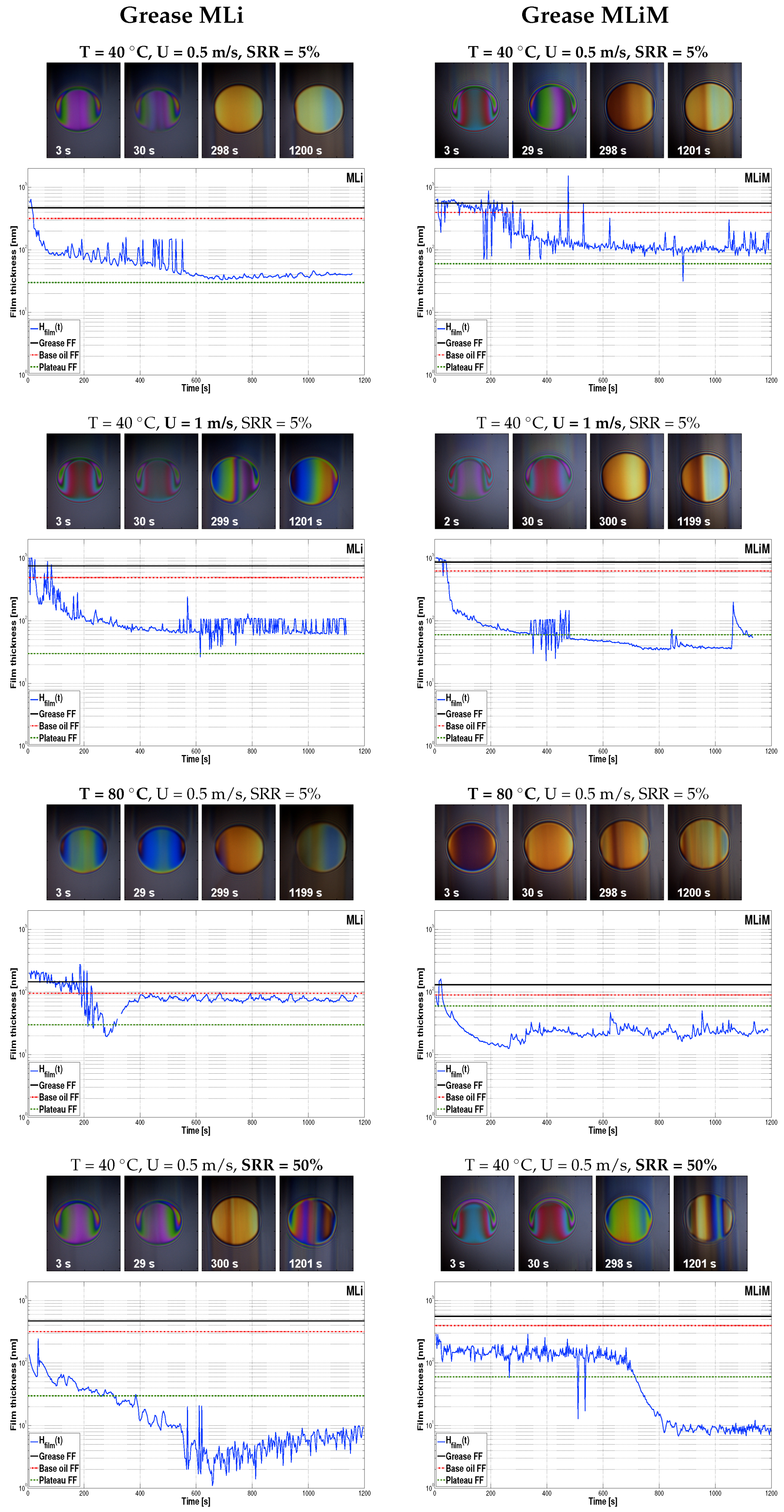
3.2. Central Film Thickness Measured over Time

The central film thickness of grease MLi, measured over time in the ball-on-disc contact at a temperature of 40 C, 5% of SRR and under an entrainment speed of 0.5 m/s is shown in Figure 5.
The fully flooded result measured under the same operating conditions but using a scoop is shown as a black horizontal line and a red dash-dotted line for the grease and base oil, respectively. The film thickness value corresponding to the plateau found at low speeds (see Figure 4) on the film thickness curves of the each grease under fully flooded conditions is also represented as a green dashed line. In the same figure, pictures of the film thickness profile over the contact area are also shown and were obtained using the SLIM method. Although these pictures do not correspond directly to the central film thickness curves, they should be illustrative of the film thickness evolution over time under these operating conditions.
It can be generally observed that the initial film thickness values were similar, but frequently higher than the fully flooded film thickness of each grease under the same operating conditions. In the case of the polymer greases, it was common to find even higher values, closer to the film thickness plateau under low speeds. At just a few seconds into the test, the film thickness of all greases dropped quickly. After some time, the film thickness decay rate slowed considerably, reaching the stabilization stage, as expected from the literature [14].
In the stabilization zone, the film thickness changes little with time, and it may decrease or increase very slowly, but it is frequent to observe considerable scatter as the thickener lumps cross the contact. Although this was observed for all greases, it is especially relevant in the case of the polymer greases, where larger and more frequent lumps cross the contact very frequently; this was reflected in high film thickness peaks. Sometimes the opposite was observed and the replenishment suddenly failed and a very sharp valley was formed. It was also common for the replenishment to improve for a while, and consequently, the film thickness also increased. The grease behaviour is chaotic [30] so this loss and recovery balance seems completely random and independent of grease formulation. However, vibrations, centrifugal forces, and/or mechanical degradation of the thickener matrix and consequent oil re-flow, could all explain this loss and supply mechanism [7,12].
By analysing the film thickness pictures, it is also possible to see that, generally, in the first 100 s of operation, the film thickness profile resembled a “horse-shoe” which is typical of a fully flooded contact. As the time increased, this profile continuously changed until starvation was reached. As an example, Figure 6 shows the top view of the film thickness profile of grease MLi under the operating conditions of Test 3 (see Table 3), after 5, 29, and 140 s of test time. In the same figure, cross-section film thickness curves were shown, taken over a central line parallel to the rolling direction and over a line transverse to the rolling direction. From these curves, it is possible to observe the evolution of the central and minimum film thicknesses during the test. As the time increases and the contact gets further starved, a ratio of h m / h 0 c 1 and starved conditions are reached.
Figure 7 and Figure 8, show the central film thickness curves of the M2, M5, MLi, and MLiM greases measured over time, under the operating conditions reported in Table 3. All curves show behaviour similar to the that reported for the MLi grease in Figure 5. To analyse the influences of different operating conditions, each test was compared to the reference test (Test 1). The average and standard deviation of the film thickness in the stabilization zone are shown in Table 4 for all tests and greases. The zero speed film thickness measured at the end of the test did not shown any relationship with regards to grease formulation or operating conditions.
At the beginning of Test 1, all greases showed a film thickness value higher than the greases’ fully flooded result, which quickly decreased to film thickness values below the fully flooded base oil result. In the case of the lithium-thickened greases, the film thickness value in the stabilization zone was higher, although very close to the greases’ film thickness plateau at low speeds.
When the tests were performed under higher entrainment speeds (Test 2), the film thickness decay rate increased for all greases. Once again, the polymer greases showed initial values of film thickness near the low speed plateau and lithium grease film thickness values above the greases’ fully flooded result. However, the film thickness in the stabilization zone seemed to increase for the M5 and MLi greases, but decreased in the cases of greases M2 and MLiM. According to Table 4, the film thickness’ standard deviation in this zone increased for all greases apart from MLiM.
In the tests performed at higher temperatures (Test 3), all greases showed very high film thickness values in the first seconds, gradually decreasing to values near the film thickness of the base oil under fully flooded conditions. The only exception was grease MLiM whose film thickness dropped to very low values, even lower than the base oil or the low speed plateau. At this temperature (80 C), the scatter was considerably higher than at 40 C, especially for the polymer greases, as can be seen in Table 4.
Finally, the tests performed at higher SRR (Test 4) showed that replenishment is considerable affected by an increase in the sliding speed. Although the initial film thickness was smaller than both fully flooded results of grease and base oil, the film decay rate was slower than that for the other tests. However, the film thickness in the stabilization zone was reached at smaller film thickness values than for the reference test, as shown in Table 4.
The tests performed at an SRR of 50% proved to be extremely harsh on the surface of the glass disc. It was very frequent for the track to get damaged and the film thickness could no longer be evaluated, a phenomenon which speaks for itself regarding how SRR affects the replenishment. Furthermore, and according to the film thickness profile pictures, the system struggled to keep the ball in place (clearly observed in the case of the M5 and MLi greases above 600 s) increasing the difficulty of obtaining representative film thickness curves under these operating conditions. Once again, the time at which the tests failed or the surface got damaged was found to be random.
The relationship between the grease formulation (thickener type or base oil nature) and the film thickness under starved conditions is not clear. However, it seems that the polymer greases generally produce higher film thickness values, especially when there is thickener material crossing the contact, which happens much more often than for the lithium complex-thickened greases.

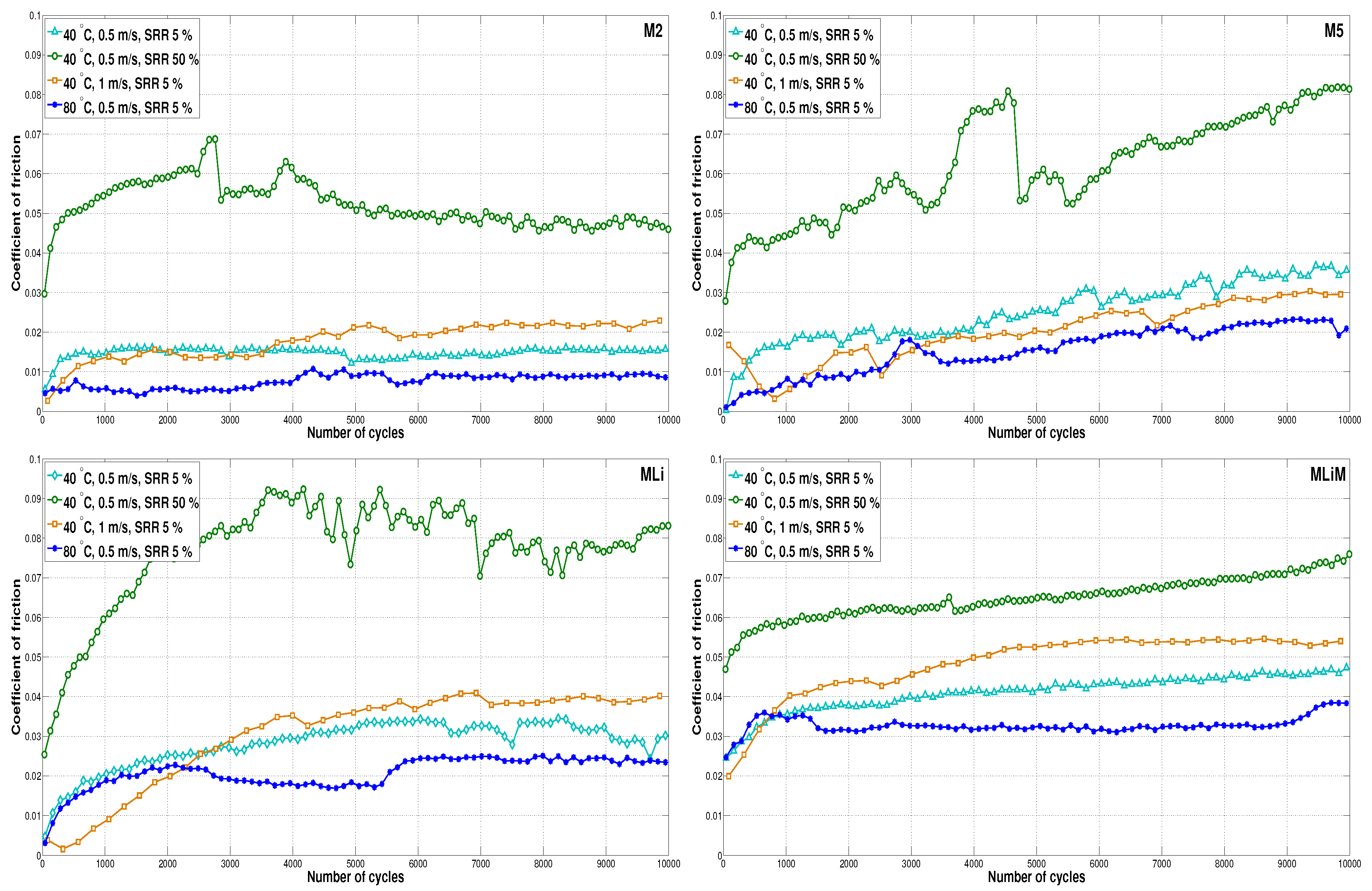
3.3. Coefficient of Friction Results

The COF was measured over time under constant operating conditions in a ball-on-disc device without using the scoop to force grease back into track. Each test was repeated twice, and the results were averaged. The average curve is shown in Figure 9 for the M2, M5, MLi and MLiM greases. The results are plotted versus the number of ball revolutions.
By analysing Figure 9, it is possible to see that the coefficient of friction increased as the number of cycles increased. Since the operating conditions were kept constant along the test, this phenomenon was due to the film thickness decay as the replenishment changed from fully flooded to starved conditions. For certain greases and under certain operating conditions, the coefficient of friction increased continuously over the test duration, while for others, it reached a steady state, similar to what was observed for the film thickness results. The average coefficient of friction for the last 2000 ball revolutions is shown in Table 5. However, in this case, there is a clear trend regarding the average coefficient of friction ( μ ¯ s t ), of the different greases in the last cycles of the test:
μ ¯ s t M L i M > μ ¯ s t M L i > μ ¯ s t M 5 > μ ¯ s t M 2 .
The fact that MLiM shows the highest COF should be due to a combination of a high viscosity mineral base oil and a lithium complex thickener. The mineral-based oils generally produce higher COF values [31], and the high viscosity should promote higher viscous friction and quicker starvation (starvation phenomenon happening with less operation time and at lower speeds).
These results, in addition to those reported in the previous section, show that even under starved conditions, the polymer greases tend to provide thicker films and smaller coefficients of friction in the stabilization stage. The only test where this trend was not so clear was under an SRR of 50%. In this situation, there was a large amount of scatter for some of the measurements related to the same problems already reported for the film thickness results. Under high loads and high SRRs, the system struggled to keep the ball in place due to high friction forces. Furthermore, the lubricant film broke and built up very fast as the replenishment changes and thickener lumps crossed the contact, making it very difficult to obtain coherent measurements under this condition.
The analysis of the results measured under different operating conditions showed that the trends were very similar between greases. By increasing the entrainment speed, the COF grew quicker and its value in the stabilization zone was higher than that at lower entrainment speeds which should be due to stronger starvation. The same effect was observed for tests performed at higher SRR values, but the value of the COF in the stabilization zone was even higher. On the other hand, the tests performed at higher operating temperatures were associated with lower COF values due to the decrease in the viscous friction and better replenishment due to the reduced grease consistency and improved oil-bleeding [12].

4. Conclusions

Film thickness measurements were performed in a ball-on-disc device under different operating conditions. In order to promote starvation, the scoop, which is generally used to ensure fully flooded conditions, was removed. Two different tests were performed to measure film thickness under increasing speed or over time. It was common to find a very high deviation in the results and the repeatability was often low, showing that the mechanisms of recovery and the loss of lubricant at the inlet of the contact are extremely random and chaotic [30].
Regarding the tests performed with the lithium-thickened greases under increasing entrainment speeds, it was possible to identify the speed at which starvation occurred. This speed seemed to increase with the operating temperature, suggesting that replenishment is better at high temperatures. In fact, the results of all greases were closer to the fully flooded result at higher temperatures [12].
As soon as starvation occurred, the film thickness dropped with increasing speed. However, it tended to stabilize and became independent of speed, at least for the tested lithium greases. Still, recovery was sometimes observed as the film thickness increased again.
In the case of the polymer greases, it was difficult to identify the speed at which starvation really occurred. However, it was possible to see a clear decrease in the film thickness values for the whole speed range tested.
Regarding the tests performed over time under constant operating conditions, it was found that the film thickness generally started at very high values and decreased very fast as time progressed. The decay rate slowed down after a while and a stabilization period was reached. Film recovery was often observed as the film thickness suddenly increased again. The effects of increasing the speed, slide-to-roll ratio, and operating temperature on the starved film thickness were addressed.
A very high standard deviation was found for certain operating conditions and all greases. However, in the case of the polymer thickened greases, the scatter was generally higher, suggesting that thickener lumps of larger size crossed the contact more often than for the lithium-thickened greases. Furthermore, the average film thickness in the stabilization zone was also frequently higher for the polymer greases, even for grease M2 formulated with the base oil of lowest viscosity.
Finally, the coefficient of friction was also measured over time. The COF quickly increased with time until it also reached a stabilization stage. In this region, it was observed that the polymer greases showed smaller coefficient of friction than lithium-thickened greases under the same operating conditions. The effect of changing the operating conditions on the coefficient of friction under starved conditions was also addressed, and it correlated fairly well with the results obtained in the film thickness tests, in general. In comparison with Test 1, the following trends were generally observed:
  • Increasing the entrainment speed led to faster starvation due to the grease being pushed away from the contact and therefore, there was less time for the film to recover. As a consequence, the COF was higher;
  • An increasing temperature led to later starvation (both in speed and time) and better replenishment due to decreased consistency, reduced bled oil viscosity, and improved oil-bleeding [12]. As a consequence, the COF reduced;
  • AN increasing SRR led to faster starvation and reduced film thickness due to grease shearing and less time for the film to recover. Again, this led to an increased COF.
This work focused only on the very recent polymer-thickened greases [18,27,28,32,33,34] and the very common—and already proven—good performance, multi-purpose, lithium-thickened greases [4,35,36]. The experimental tests shown here should be extended to different thickener-base oil combinations to determine whether the observed phenomena could be generally applied to different formulations.
Grease lubrication is extremely complex. Not only is its behaviour fairly difficult to predict, but also, it is extremely application dependent. In this work, the film formation and friction under starved conditions were addressed in a ball-on-disc contact, but the behaviour in a rolling bearing can be considerably different. Although the tested polymer-thickened greases showed better performances in the single contact tests, it cannot be assumed that they should also provide better wear protection or increased rolling bearing life for all applications. There are so many variables involved (consistency, thickener type and/or content, base oil viscosity/nature, additive package, etc.) and so many different performance requisites (load carrying capability, improved oil-bleeding, low and high temperature properties, low friction, etc.) that grease formulation R&D should be increasingly more application oriented [36].

Author Contributions

Formal analysis, D.E.P.G.; Investigation, D.E.P.G.; Methodology, D.E.P.G. and J.H.O.S.; Project administration, A.V.C. and J.H.O.S.; Supervision, A.V.C. and J.H.O.S.; Writing–original draft, D.E.P.G.; Writing–review & editing, D.E.P.G., A.V.C. and J.H.O.S.

Funding

The authors gratefully acknowledge the funding through several projects and grants without whom this work would not have been possible:
  • FCT under the individual PHD grant SFRH/BD/111868/2015;
  • NORTE-01-0145-FEDER-000022–SciTech–Science and Technology for Competitive and Sustainable Industries, cofinanced by Programa Operacional Regional do Norte (NORTE2020), through Fundo Europeu de Desenvolvimento Regional (FEDER);
  • LAETA under the project UIDS/EMS/50022/2013.

Conflicts of Interest

The authors declare no conflict of interest.

References

  1. Wedeven, L.D.; Evans, D.; Cameron, A. Optical Analysis of Ball Bearing Starvation. J. Lubr. Technol. 1971, 93, 349. [Google Scholar] [CrossRef]
  2. Chiu, Y.P. An Analysis and Prediction of Lubricant Film Starvation in Rolling Contact Systems. ASLE Trans. 2008, 17, 22–35. [Google Scholar] [CrossRef]
  3. Pemberton, J.; Cameron, A. A mechanism of fluid replenishment in elastohydrodynamic contacts. Wear 1976, 37, 185–190. [Google Scholar] [CrossRef]
  4. Lugt, P.M. Grease Lubrication in Rolling Bearings; Wiley: Hoboken, NJ, USA, 2013. [Google Scholar]
  5. Cousseau, T.; Björling, M.; Graça, B.; Campos, A.; Seabra, J.; Larsson, R. Influence of grease bleed oil on ball-on-disc lubrication. In Proceedings of the 5th World Tribology Congress, Torino, Italy, 8–13 September 2013; Volume 2, pp. 1109–1112. [Google Scholar]
  6. Chen, J.; Tanaka, H.; Sugimura, J. Experimental Study of Starvation and Flow Behavior in Grease-Lubricated EHD Contact. Tribol. Online 2015, 10, 48–55. [Google Scholar] [CrossRef] [Green Version]
  7. Cann, P.M.E. Thin-film grease lubrication. Proc. Inst. Mech. Eng. Part J J. Eng. Tribol. 1999, 213, 405–416. [Google Scholar] [CrossRef]
  8. Aihara, S.; Dowson, D. A study of film thickness in grease lubricated elastohydrodynamic contacts. In Proceedings of the 5th Leeds-Lyon Symposium on Tribology, Leeds, UK, September 1978. [Google Scholar]
  9. Kauzlarich, J.J.; Greenwood, J.A. Elastohydrodynamic Lubrication With Herschel-Bulkley Model Greases. ASLE Trans. 1972, 15, 269–277. [Google Scholar] [CrossRef] [Green Version]
  10. Åström, H.; Östensen, J.O.; Höglund, E. Lubricating Grease Replenishment in an Elastohydrodynamic Point Contact. J. Tribol. 1993, 115, 501. [Google Scholar] [CrossRef]
  11. Cann, P.M.; Lubrecht, A.A. Bearing performance limits with grease lubrication: the interaction of bearing design, operating conditions and grease properties. J. Phys. D Appl. Phys. 2007, 40, 5446. [Google Scholar] [CrossRef]
  12. Cann, P.M. Starvation and reflow in a grease-lubricated elastohydrodynamic contact. Tribol. Trans. 1996, 39, 698–704. [Google Scholar] [CrossRef]
  13. Kaneta, M.; Ogata, T.; Takubo, Y.; Naka, M. Effects of a thickener structure on grease elastohydrodynamic lubrication films. Proc. Inst. Mech. Eng. Part J J. Eng. Tribol. 2000, 214, 327–336. [Google Scholar] [CrossRef]
  14. Mérieux, J.S.; Hurley, S.; Lubrecht, A.A.; Cann, P.M. Shear-Degradation of Grease and Base Oil Availability in Starved EHL Lubrication; Elsevier: New York, NY, USA, 2000. [Google Scholar]
  15. Cann, P. Grease Lubrication of Rolling Element Bearings—role of the grease thickener. Lubr. Sci. 2007, 19, 183–196. [Google Scholar]
  16. van Zoelen, M.T.; Venner, C.H.; Lugt, P.M. Prediction of film thickness decay in starved elasto-hydrodynamically lubricated contacts using a thin layer flow model. Proc. Inst. Mech. Eng. Part J J. Eng. Tribol. 2009, 223, 541–552. [Google Scholar] [CrossRef]
  17. van Zoelen, M.T.; Venner, C.H.; Lugt, P.M. The prediction of contact pressure-induced film thickness decay in starved lubricated rolling bearings. Tribol. Trans. 2010, 53, 831–841. [Google Scholar] [CrossRef]
  18. Gonçalves, D.; Graça, B.; Campos, A.V.; Seabra, J.; Leckner, J.; Westbroek, R. On the film thickness behaviour of polymer greases at low and high speeds. Tribol. Int. 2015, 90, 435–444. [Google Scholar] [CrossRef]
  19. Meijer, D.; Lankamp, H. Polymer Thickened Lubricating Grease. U.S. Patent 5846918A, 12 March 1996. [Google Scholar]
  20. Meijer, D.; Lankamp, H. Polymer Thickened Lubricating Grease. U.S. Patent 5874391A, 23 February 1999. [Google Scholar]
  21. Dodson, S.; Newman, R. Grease Composition. U.S. Patent 3850828A, 26 November 1974. [Google Scholar]
  22. Mitacek, B. Grease; Technical Report. Available online: https://patents.google.com/patent/US3392119 (accessed on 10 September 2018).
  23. Gonçalves, D.; Graça, B.; Campos, A.; Seabra, J. Film thickness and friction behaviour of thermally aged lubricating greases. Tribol. Int. 2016, 1–11. [Google Scholar] [CrossRef]
  24. Cann, P.M.; Spikes, H.A.; Hutchinson, J. The Development of a Spacer Layer Imaging Method (SLIM) for Mapping Elastohydrodynamic Contacts. Tribol. Trans. 1996, 39, 915–921. [Google Scholar] [CrossRef]
  25. Cen, H.; Lugt, P.M.; Morales-Espejel, G.E. Film Thickness of Mechanically Worked Lubricating Grease at Very Low Speeds. Tribol. Trans. 2014, 57. [Google Scholar] [CrossRef]
  26. Cen, H.; Lugt, P.M.; Morales-Espejel, G.E. On the film thickness of grease lubricated contacts at low speeds. Tribol. Trans. 2014, 57. [Google Scholar] [CrossRef]
  27. Gonçalves, D.; Marques, R.; Graça, B.; Campos, A.V.; Seabra, J.H.; Leckner, J.; Westbroek, R. Formulation, rheology and thermal aging of polymer greases—Part II: Influence of the co-thickener content. Tribol. Int. 2015, 87, 171–177. [Google Scholar] [CrossRef]
  28. Gonçalves, D.; Graça, B.; Campos, A.; Seabra, J. On the friction behaviour of polymer greases. Tribol. Int. 2015, 93, 399–410. [Google Scholar] [CrossRef]
  29. De Laurentis, N.; Kadiric, A.; Lugt, P.M.; Cann, P.M. The Influence of Bearing Grease Composition on Friction in Rolling/Sliding Concentrated Contacts. Tribol. Int. 2015, 94, 624–632. [Google Scholar] [CrossRef]
  30. Lugt, P.M.; Velickov, S.; Tripp, J.H. On the Chaotic Behavior of Grease Lubrication in Rolling Bearings. Tribol. Trans. 2009, 52, 581–590. [Google Scholar] [CrossRef]
  31. Brandão, J.A.; Meheux, M.; Ville, F.; Seabra, J.H.; Castro, J. Comparative overview of five gear oils in mixed and boundary film lubrication. Tribol. Int. 2012, 47, 50–61. [Google Scholar] [CrossRef]
  32. Gonçalves, D.; Graça, B.; Campos, A.V.; Seabra, J.; Leckner, J.; Westbroek, R. Formulation, rheology and thermal ageing of polymer greases—Part I: Influence of the thickener content. Tribol. Int. 2015, 87, 160–170. [Google Scholar] [CrossRef]
  33. Gonçalves, D.; Cousseau, T.; Gama, A.; Campos, A.; Seabra, J.H. Friction torque in thrust roller bearings lubricated with greases, their base oils and bleed-oils. Tribol. Int. 2016. [Google Scholar] [CrossRef]
  34. Cousseau, T.; Björling, M.; Graça, B.; Campos, A.; Seabra, J.H.O.; Larsson, R. Film thickness in a ball-on-disc contact lubricated with greases, bleed oils and base oils. Tribol. Int. 2012, 53, 53–60. [Google Scholar] [CrossRef] [Green Version]
  35. Lugt, P.M. A Review on Grease Lubrication in Rolling Bearings. Tribol. Trans. 2009, 52, 470–480. [Google Scholar] [CrossRef] [Green Version]
  36. Lugt, P.M. Modern Advancements in Lubricating Grease Technology. Tribol. Int. 2016, 97, 467–477. [Google Scholar] [CrossRef]
Figure 1. Atomic Force Microscopy (AFM) images of the surface of the M2, M5, MLi, and MLiM greases. Each picture shows a 5 μ m × 5 μ m region.
Lubricants 06 00082 g001
Figure 2. Diagram of the optical interference technique used in the EHD2 equipment.
Lubricants 06 00082 g002
Figure 3. Central film thickness of a ball-on-disc contact, measured over increasing entrainment speeds for the M5 and MLi greases at T = 20 C and SRR (slide-to-roll ratio) = 5%.
Lubricants 06 00082 g003
Figure 4. Film thickness curves of the M2, M5, MLi, and MLiM greases, measured over increasing entrainment speeds at 20, 40, and 80 C.
Lubricants 06 00082 g004aLubricants 06 00082 g004b
Figure 5. Central film thickness of a ball-on-disc contact, lubricated with the MLi grease under U = 0.5 m/s, F = 50 N, SRR = 5%, and T = 40 C.
Lubricants 06 00082 g005
Figure 6. Film thickness profiles of the MLi grease, taken during Test 3: top view (top) and cross sections parallel to the rolling direction (bottom left) and transverse to the rolling direction (bottom right).
Lubricants 06 00082 g006
Figure 7. Film thickness of the M2 and M5 greases measured over time under constant operating conditions.
Lubricants 06 00082 g007
Figure 8. Film thickness of the MLi and MLiM greases measured over time under constant operating conditions.
Lubricants 06 00082 g008
Figure 9. Coefficient of Friction (COF) curves of the M2, M5, MLi and MLiM greases, measured over time under different operating conditions.
Lubricants 06 00082 g009
Table 1. Properties of the test greases.
Grease ReferenceM2M5MLiMLiMUnits
Thickener typePPPPLiXLiX
Base oil naturePAOPAOPAO + 5%EMIN
Thickener content131317.510.6%
Elastomer content02.601.7%
Worked penetration (ISO 2137)269249276n.a. 10 1 mm
NLGI2322
Storage Modulus 1 G 80 C21,34729,81022,28515,820Pa
Loss Modulus 1 G 4596602971021861Pa
Cross-over stress 2 τ c o 80 C1879264163Pa
Yield stress 3 τ y 112313337Pa
Base oil viscosity (ASTM D445)40 C48.0178.7153.3mm 2 /s
100 C8.021.415.7
Bleed oil viscosity (ISO 12058)40 C49.3779.1135.2159.9mm 2 /s
100 C8.393.318.916.6
1 —Values measured in a plate-plate rheometer at the LVE region, under a frequency of ω = 1 rad/s and a gap of 1 mm; 2 —Stress value at which G = G ; 3 —Stress value at which G = 0.90·G ( L V E r e g i o n ) .
Table 2. EHD2—Specimens for film thickness and coefficient of friction measurements.
Surface PropertiesGlass DiscSteel BallSteel Disc
Radius, R x , y [mm]9.525
Roughness, R a [ μ m]5<20
MaterialGlassAISI 52100
Young’s Modulus64207
Poisson coefficient0.290.2
Table 3. Operating conditions of the central film thickness measurements and coefficient of friction measurements.
Test Number1 (Ref.)234
Entrainment speed—U [m/s]0.510.50.5
Temperature—T [ C]40408040
Slide-to-roll ratio—SRR [%]55550
Load—F [N]50505050
Table 4. Average ( h ¯ s t ) and standard deviation ( σ % ) of the central film thickness of the M2, M5, MLi, and MLiM greases from 1000 to 1200 s. The fully flooded film thickness result ( h G ) is also shown under the same operating conditions.
Test ConditionsTest 1 40 C 0.5 m/s 5%Test 2 40 C 1 m/s 5%Test 3 80 C 0.5 m/s 5%Test 4 40 C 0.5 m/s 50%Trends in Starvation Tests
M2 h G 19231898192 *
h ¯ s t 1238032130 U h ¯ s t
σ % 17568510 T h ¯ s t
M5 h G 320551121320 *
h ¯ s t 1121216650 U h ¯ s t
σ % 138515612 T h ¯ s t
MLi h G 470756146470 *
h ¯ s t 4179767 U h ¯ s t
σ % 527829 T h ¯ s t
MLiM h G 558867131558 *
h ¯ s t 12359249 U h ¯ s t
σ % 34541311 T h ¯ s t
h G and h ¯ s t in nm. σ % in %. * fully flooded values measured under the operating conditions of Test 1.
Table 5. Average COF under starved conditions ( μ ¯ s t ) for the last 2000 cycles of the M2, M5, MLi and MLiM greases.
Test ConditionsTest 1 40 C 0.5 m/s 5%Test 2 40 C 1 m/s 5%Test 3 80 C 0.5 m/s 5%Test 4 40 C 0.5 m/s 50%Trends
M2 μ ¯ s t 0.0160.0220.0090.047 U μ ¯ s t
T μ ¯ s t
S R R μ ¯ s t
M5 μ ¯ s t 0.0350.0270.0220.079 U μ ¯ s t
T μ ¯ s t
S R R μ ¯ s t
MLi μ ¯ s t 0.0310.0390.0240.079 U μ ¯ s t
T μ ¯ s t
S R R μ ¯ s t
MLiM μ ¯ s t 0.0460.0540.0350.073 U μ ¯ s t
T μ ¯ s t
S R R μ ¯ s t

