Abstract
The present study provides molecular insight into the mechanisms underlying energy dissipation and lubrication of a smooth contact lubricated by an ionic liquid. We have performed normal and lateral force measurements with a surface forces apparatus and by colloidal probe atomic force microscopy on the following model systems: 1-ethyl-3-methyl imidazolium bis-(trifluoro-methylsulfonyl) imide, in dry state and in equilibrium with ambient (humid) air; the surface was either bare mica or functionalized with a polymer brush. The velocity-dependence of the friction force reveals two different regimes of lubrication, boundary-film lubrication, with distinct characteristics for each model system, and fluid-film lubrication above a transition velocity . The underlying mechanisms of energy dissipation are evaluated with molecular models for stress-activated slip and flow, respectively. The stress-activated slip assumes that two boundary layers (composed of ions/water strongly adsorbed to the surface) slide past each other; the dynamics of interionic interactions at the slip plane and the strength of the interaction dictate the change in friction -decreasing, increasing or remaining constant- with velocity in the boundary-film lubrication regime. Above a transition velocity , friction monotonically increases with velocity in the three model systems. Here, multiple layers of ions slide past each other (“flow”) under a shear stress and friction depends on a shear-activation volume that is significantly affected by confinement. The proposed friction model provides a molecular perspective of the lubrication of smooth contacts by ionic liquids and allows identifying the physical parameters that control friction.
1. Introduction
Ionic liquids have gained growing interest in lubrication engineering because of their chemical and thermal stability, vanishingly low vapor pressure, and non-flammability [1,2,3]. Key for the lubricious behavior of ionic liquids is their ability to remain firmly adsorbed on many different substrate’s surfaces at high contact stresses [4,5]—especially on charged surfaces [6] and under an applied surface potential [7]—and thereby to provide a plane of low shear strength, which mitigates friction. Since ionic liquids were first proposed as potential lubricants in Ye’s pioneering work [8], numerous studies have examined the layering structures of ionic liquids at solid-liquid interfaces and under nanoconfinement, and have correlated them to friction [9,10,11,12,13,14,15].
To date, it is known that friction and adhesion depend on the number of layers of ions that remain between the confining surfaces, i.e., friction and adhesion are quantized and increase with a decrease of the number of layers [12]. Experiments show variations of the coefficient of friction with the molecular composition of the ionic liquid [11,14], surface charge [6], potential [7] and in the presence of water [13,14,16]; see recent review [5]. Various works have reported that co-ions also affect friction on charged surfaces, which implies that they may also be present in the near-surface region likely due to strong ion-ion correlations [11]. Friction measurements in ionic liquids confined between a silica tip and a graphite surface demonstrate that ultralow friction can be switched on and off in situ by polarizing the surface relative to the reference electrode [17]. According to MD simulations, one possible explanation is that the slip plane moves from the solid-liquid interface to the interior of the film with the increase in potential, while the strong electrostatic attraction to the surface hinders squeeze out of the liquid [6]. Although it is evident from these studies that nanoscale friction is affected by the molecular composition of the ionic liquid and by the surface properties, the molecular (chemical) features that dictate energy dissipation and friction are still unclear, with the lack of such fundamental insight hindering control of friction and lubrication by ionic liquids.
Molecular interfacial processes that control sliding and friction can be understood in the context of Eyring’s transition state theory [18] and his molecular model for liquid viscosity [19]. Here, an externally applied force enhances the rate of liquid molecules passing over a transition state by reducing the energy barriers, thereby promoting slip between layers of molecules and liquid flow [18,19]. A difference in initial and final states indicates that a structural evolution has taken place (e.g., wear or a chemical reaction). In contrast, if the initial and final states are degenerate (i.e., of equal energy), no structural evolution occurs. The present work is focused only on the latter situation.
Eyring’s molecular model for liquid viscosity [19] has underpinned several theories of boundary lubrication [20]. The model essentially describes the sliding speed/shear stress relationship between layers of molecules. Later, it was adapted by Briscoe and Evans [21] to describe friction between opposing Langmuir-Blodgett boundary layers, for which they observed a logarithmic increase of friction with velocity. Schallamach [22] described sliding of rubber against glass also as an activated slip process, where adhesive bonds between the polymer and the countersurface thermally form and rupture according to rates with characteristic times and respectively. This model yields an increase in friction with velocity at slow sliding velocities, while at high velocities, friction decreases with sliding velocity because the (transient) bonds do not have sufficient time to form. Moreover, Schallamach extended the concept of molecular bond to larger nanodomains (“junctions”) composed of several molecules. Drummond et al. [23] additionally considered that the molecular junctions can also break when they are stretched over a critical yield length (). This friction model is adapted here to ionic liquid lubrication.
The present study aims to provide fundamental insight into the governing mechanisms of energy dissipation at a single asperity sliding contact composed of an atomically flat mica surface and a smooth silica colloid lubricated by 1-ethyl-3-methyl imidazolium bis-(trifluoromethylsulfonyl) imide (abbreviated as [EMIM][TFSI]), either dried in vacuo or in equilibrium with ambient air, the latter implying the presence of water. We use colloidal probe lateral force microscopy to measure friction as a function of load and sliding velocity and model the friction force considering the dynamic formation and rupture of reversible intermolecular (interionic) bonds at the slip plane. The study is extended to polymer brush-bearing surfaces lubricated by the same ionic liquid; the polymer brush consists of poly(l-lysine)-graft-poly(ethylene glycol) (abbreviated as PLL-g-PEG). Precedent work has shown that the presence of water in this particular ionic liquid influences the interfacial structure [24] and the friction coefficient [25] and that it is a very good solvent of PEG brushes [26]; these findings have motivated the selection of [EMIM][TFSI] for this study. We describe the molecular interfacial processes during sliding as activated slip and flow processes at slow and fast sliding velocities, respectively. The analysis of the friction force under the umbrella of this theory provides molecular insight into the mechanisms underlying ionic liquid lubrication and an interpretation of the effects of molecular features of ionic liquid, water and polymer brush on friction.
2. Results
2.1. Interfacial Structure
The three systems under investigation, vacuum-dry [EMIM][TFSI] and equilibrated at 44% RH on uncoated mica surfaces, and the vacuum-dry ionic liquid (IL) on brush-bearing mica are referred to as IL-0%, IL-44%, and PEG-IL, respectively, for concisesness. Details about the materials and methods can be found in the Materials and Methods section. Figure 1a–c shows representative surfaces forces measured with a surface forces apparatus (SFA). The long-range repulsion in Figure 1a in IL-0% (red diamonds) extends out to separations () of ~30 nm and decays exponentially with . This repulsion is consistent with a surface force of electrostatic origin in a highly concentrated electrolyte [27,28]. At separations smaller than ~ 8 nm (Figure 1b), a stronger short-range repulsion—originated by the entropy loss of the confined molecules (also called solvation force)—dominates the interaction between the surfaces, in agreement with literature [9,14,29,30]. The arrangement of the ions in layers at the solid-liquid interface is reflected in an oscillatory density profile, which leads to steps in the force-distance curve every time one layer of ions, assumed to be composed of ion pairs to preserve the electroneutrality of the system, is squeezed-out out of the film. The thickness of these layers is ∆ ~ 0.7 nm, which is in good agreement with previous works [31]. It is worth noting that the IL is not completely squeezed-out at the highest applied loads (note the hard wall at ~ 3 nm), but it remains adsorbed to the mica surfaces. We presume that the remaining liquid film is needed to preserve electroneutrality, since mica has a high negative charge [27,32]. Layers of the same size are measured in IL-44% (blue empty triangles), which suggests that the arrangement of the ions is not significantly affected by the presence of water. Nevertheless, an enrichment of water in the remaining film, and hence, a different interfacial composition, as inferred from MD simulations [33], cannot be excluded but the structure of this thin film cannot be examined in SFA experiments.
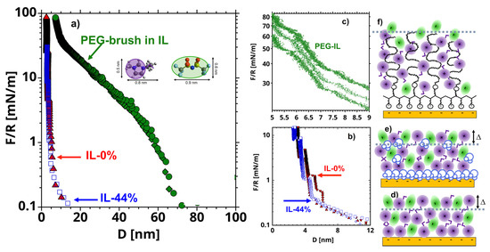
Figure 1.
(a) Representative surface forces (normalized by the radius of the cylindrical lense = 20 mm) as a function of the distance () between mica surfaces measured with a surface forces apparatus in vacuum dry [EMIM][TFSI] (IL-0%, red filled symbols), [EMIM][TFSI] equilibrated with 44% RH (IL-44%, blue empty symbols), and PEG-brushes in [EMIM][TFSI] (PEG-IL, green filled symbols). The short-range surface forces are shown in (b) for IL-0% and IL-44% and in (c) for PEG-IL, while the schematics of the interfacial stuctures are shown in (f), (d) and (e), respectively. The average hertzian stress at the maximum load of 100 mN/m is ~7.7 MPa. The inset in (a) shows the molecular structure of [EMIM][TFSI] and the simplified geometry used for the cartoons in this work. The violet circles with short tails represent the [EMIM]+ cations, and the green ellipses represent the [TFSI]- anions. Water molecules are shown in blue in (e) and the polymer chains in black in (f).
In PEG-IL, a much longer-ranged repulsive force is detected with an onset varying between 60 and 80 nm across different experiments, which is attributed to the surface-adsorbed polymer. Our previous work [26] unambiguously demonstrated that the poly(l-lysine) backbone adsorbs on the mica surface and the PEG chains extend away from the surface in the IL, thereby forming a strongly stretched polymer brush. There is evidence that the imidazolium cations hydrogen-bond preferentially to PEG chains, which effectively provides a neat (small) positive charge to the polymer, which then behaves like a polyelectrolyte [26,34,35]. At high compressions (10 < < 50 mN/m), we observe discrete film-thickness transitions (or steps) embedded into the steric repulsion (Figure 1c), which are reminiscent of those measured in the neat IL (Figure 1b), thereby suggesting that the polymer brush is desolvated at the highest applied loads. The thermal fluctuations at a polymer-liquid interface are believed to disrupt the layered arrangement of liquid molecules [36], and therefore these results are surprising. Nonetheless, the squeeze-out of layers of ions was only observed at high compressions, at which the thermal fluctuations are expected to be strongly suppressed due to the strong confinement of the PEG chains. More details about the properties of PEG brushes in this IL can be found elsewhere [26].
Figure S1 in the Supplementary Information (SI) shows that the normal surface forces measured by colloidal probe Atomic Force Microscopy (AFM) are in qualitative agreement with those measured by SFA. Further, there is an excellent reproducibility of the results over an area of 10 µm by 10 µm, where friction was measured, which confirms the uniformity of the interfacial structure in all three systems. The QI image of the PEG-brush in the liquid is shown in Figure S2. The sharp tip is not capable of resolving the PEG chains due to their flexibility. The features on the surface (~1 nm in height) correspond to the PLL backbone that is anchored to the mica surface through electrostatic interactions. Figure S2 reveals the homogeneous coverage of the surface with the copolymer.
2.2. Friction-Force Measurements
Friction-force measurements were performed by Lateral Force Microscopy on bare and brush-bearing mica surfaces with a silica colloid as a function of the load and of the sliding velocity. Figure 2a–c shows representative friction-force measurements. An increase in friction is observed with an increase in load for the three systems.
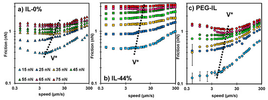
Figure 2.
Speed-dependent friction force measured in (a) IL-0% (triangles), (b) IL-44% (squares), and (c) PEG-IL (circles) at normal load ranging from 15 to 75 nN; see color legend in (a). Common in all the systems is the presence of two regimes. At sliding velocities , the friction force remains either constant, decreases or increases with velocity, while at sliding velocities , an increase of friction with the logarithm of the sliding velocity is always observed. Error bars are usually smaller than the symbol size and therefore not visible. The dashed line shows the approximate value of ; the precisely determined values of are given in Figure S3 in the SI.
Importantly, a different velocity dependence of the friction force is observed for the three systems. In IL-0% (Figure 2a, triangles), the friction force varies non-monotonically with the sliding velocity; at the slowest velocities, it slightly decreases with velocity, whereas it rapidly increases with speed above a transition velocity that we call (see dashed line). This non-monotonic trend in friction is not unique to this system but it has been observed before for other ILs [14] and lubricants [23,37]. In IL-44% (Figure 2b, squares), friction is quasi-velocity independent at the slowest sliding velocities, before it increases with velocity; a transition velocity is thus also identified in this case (see dashed line). In PEG-IL (Figure 2c, circles), the friction force increases with speed at the highest sliding velocities, in qualitative agreement with the other model systems. In contrast, at the slowest sliding velocities, the variation of friction with velocity depends on the applied load, transitioning from a slight increase in friction with velocity at low loads to a plateau at intermediate loads. When the normal load is higher than 55 nN, a distinguishable local minimum of friction is observed at a transition velocity of ~ 10 µm/s. The change in behavior at high normal loads is attributed to an irreversible structural change in the brush configuration and it is discussed later in detail.
To ease the comparison of results across the three different systems, Figure 3 shows the friction force as a function of load at a constant sliding velocity of 1 µm/s. The coefficient of friction µ—calculated as the slope of friction as a function of load, i.e., µ—in IL-44% (µ = 0.04) is larger than in IL-0% (µ = 0.02), while the PEG-brush in the dry IL exhibits the lowest friction coefficient. The quasi-linear relation between friction and load in IL-0% and IL-44% with a positive intercept indicates the absence of a low-friction regime, in contrast to results reported for other ILs [13,14]. Therefore, we presume that the number of layers of the films confined between the two surfaces and their composition do not change with an increase in load in the range of investigated loads at 1 µm/s. A linear relation between friction and load is not observed for the PEG-coated surface in IL, which suggests that a change in the interfacial composition and/or structure might have occurred [38]. While a satisfactory agreement is found between the loading (blue) and the unloading (red) curves in IL-0% and IL-44%, a small hysteresis is observed at the smallest applied loads for the PEG brush (circles), which supports that the structural or compositional change of the polymer brush is irreversible within the time scale of this measurement.
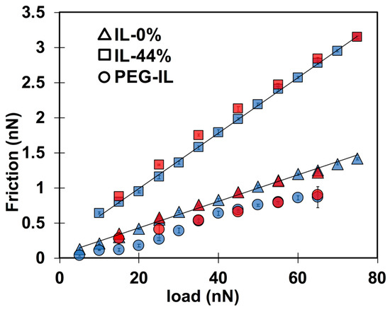
Figure 3.
Load-dependent friction force measured with a 5-m silica sphere at a constant sliding velocity of 1 m/s in IL-0% (triangles), IL-44% (squares), and in PEG-IL (circles). The blue color shows friction force while the normal load is monotonically increased (loading) and the red color gives friction force while the normal load is gradually decreased (unloading). The semi-transparent colors allow the error bars to be seen.
2.3. Identifying Molecular Mechanisms of Lubrication: Stress Activated Slip and Viscous Flow
Recognizing the commonality of the transitional frictional response of the three model systems with velocity in Figure 2, Figure 4 shows the normalized friction force by the value achieved at the transition velocity as a function of the normalized velocity by . The corresponding values of and are shown in Figure S3 in the SI. In IL-0%, this practice collapses the friction force at different loads into one master curve (triangles in Figure 4), indicating that the scaling parameters and encompass the influence of the normal load on friction. The different trends of with velocity (slightly decreasing at and increasing with velocity at ) indicate that two different mechanisms underpin the dissipated energy and friction. Similarly, the results in IL-44% collapse well into a master curve (first with a plateau and then increasing with velocity above ), except at the highest loads (65 and 75 nN, see arrows), suggesting a change of the underlying lubrication mechanism with load. It is worth noting that the normalized friction force above at loads smaller than 65 nN collapses well with the master curve of IL-0%. In case of the PEG-brush lubricated with dry IL, the collapse of the data points is excellent at the sliding velocities above , while no collapse is observed at slow velocities, which indicates that the molecular mechanisms dictating the sliding process at slow velocities vary with applied load. We propose to describe the sliding process as an activated slip of the surface-bound ions or boundary layers () and as a stress activated flow of the confined liquid film ().
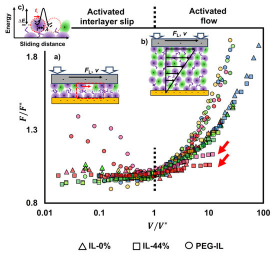
Figure 4.
Friction force () normalized by the friction value () at the transition velocity () for IL-0% (triangles), IL-44% (squares), and PEG-IL (circles) at loads between 25 and 75 nN; the color legend is the same as in Figure 2: 25 nN (blue), 35 nN (yellow), 45 nN (light green), 55 nN (green), 65 nN (pink), and 75 nN (red). The data points cluster into two groups at > 1, one for the IL-0% and IL-44% and another one for PEG-IL; the results in IL-44% agree well with the results in IL-0%, except at the highest loads (see arrows). At < 1, different trends are observed for IL-0% (friction slightly decreasing with velocity) and IL-44% (friction slightly increasing with velocity). No collapse is observed for IL-PEG at < 1, which is justified by the influence of the load on the bond dynamics dictating the sliding process (see text). For the three systems, the data at < 1 are described well as a shear-promoted thermally activated slip of the boundary layers (a), whereas the data at > 1 are described by an activated flow characterized by the activated volume of the confined liquid films (b). Both mechanisms are activated processes, meaning that the molecules (ions) need to jump over an energy barrier for slip or flow to happen, (c), which involves rupture and re-formation of intermolecular (reversible) bonds between neighbor ions while the ions rearrange during sliding. Figure S4 in the SI shows the same data but separated into three diagrams, one for each system, for more clarity.
At the high applied pressures in our friction-force measurements (>10 MPa) and slow sliding velocities (), only the boundary layers are expected to remain at the contact and slide past each other in an interlayer slip fashion (see cartoon in Figure 4a). As indicated in Figure 3, the friction coefficient is constant over the whole range of applied loads at 1 µm/s, which indicates that the same number of confined layers remains in the contact independently of the load [12]. A distinction must be made between the boundary-film lubrication regime described here and the concept of boundary-lubrication regime at a macroscopic scale, with the latter featuring high friction coefficients owing to asperity-asperity contacts. Instead, in the boundary-film lubrication regime, the surface-adsorbed IL film is capable of resisting strong stresses, and thus, it effectively lubricates the contact and yields the lowest friction. A surface charge of ~−0.05 nm−2 is found for silica in water, and hence, it is much lower than the maximum charge of mica (~−0.49 nm−2) [39]. The charge density of silica in ILs is, however, unknown. Further, silanol groups on silica surfaces may also hydrogen bond with ILs [40]. For example, IR spectroscopy revealed the formation of alkyl C–Hsilica hydrogen bonds in [EMIM][TFSI]. Accordingly, an enrichment of cations close to mica and silica surfaces is expected, and it is likely that the slip plane is located between the cation-rich boundary layers, at least in the dry IL. During sliding, the ions fluctuate within and across layers and rearrange, which involves rupture and formation of “bonds” with the neighbor ions. The interionic bonds considered here are expected to be mainly (but not only) of electrostatic nature and hydrogen bonding, and therefore, they are reversible; that is, the term bond is not used here to describe covalent bonds but only reversible intermolecular interactions.
At sliding velocities larger than , a small hydrodynamic lift may yield thicker films and provide elastohydrodynamic lubrication. A rough estimation of the hydrodynamic lift using the Hamrock-Dowson model [41] gives a film thickness 1.3 nm at V = 300 µm/s assuming that the viscosity remains constant and equal to 35 mPa·s and the load is ~ 15 nN. As described later, the viscosity is observed to increase at least by two orders of magnitude, which leads to a significant increase in the expected film thickness ( 8 nm at V ~ 10 µm/s). While this is only a very rough approximation, it suggests that a transition into the hydrodynamic regime is possible in our experiments. Here, most of the ions are not “pinned” to the surface, so they “flow” under shear loading, which also involves a slip between molecular layers, and thereby, a shear-activated process in the context of Eyring’s definition of viscosity at the molecular level (Figure 4b). It is observed that is greater in IL-44% than in IL-0% (Figure S3a), indicating that the transition into hydrodynamic lubrication is delayed by the presence of water, likely due to the higher friction in the boundary-film lubrication regime.
Stress-activated processes consider that the applied force reduces the energy barrier for the layers of molecules to slide past each other (Figure 4c), and as a consequence of it, friction will increase with the sliding velocity. While the logarithmic increase in friction with velocity above the transition velocity is common to the three investigated systems, the trends at slower velocities are more intricate and are affected by the presence of water and by the polymer brush. Figure 4 shows that, at the slowest sliding velocities, friction can increase, decrease and remain constant with increasing sliding velocity, which calls for a more complex model, as described in the following.
2.4. Molecular Model of Friction
Schallamach’s model for rubber friction [22] treats slip as a process in which the adhesive bonds between polymer molecules on the contacting surfaces are continually forming and breaking. Bond formation is described as a thermally activated process with a rate given by ( being the characteristic time for bond formation), while bond rupture is in line with Eyring’s description of a stress-promoted thermally activated process (Figure 4c); the rupture rate is given by , being the characteristic time for bond rupture. If bonds reform immediately, friction is dictated by , thereby causing friction to increase with sliding velocity; but if they do not have time to form, friction depends on and it may decrease with sliding velocity.
Here, we adapt an extension of Schallamach’s model, which was proposed by Drummond et al. [23] for friction between surfactant monolayers, to IL lubrication. The friction force is given by the sum of two independent contributions: the elastic friction ( originated from the rupture of reversible intermolecular bonds at the slip plane between the boundary layers, predominant at slow sliding speeds (), and the viscous dissipation originated by the Couette flow of the confined liquid (, which becomes prominent at fast sliding velocities ():
The confined film is treated like a viscoelastic medium with shear modulus and effective viscosity . The total contact area between the boundary layers is assumed to consist of independent nanodomains of area , each of them composed of several ions or molecules that interact across the slip plane. The ions in a nanodomain can be in pinned state (yielding a junction) or unpinned. For slip to happen, the junctions need to break, thereby implying the rupture of the intermolecular bonds across the slip plane. During sliding, the junctions thus break and re-form in an incoherent manner. The dissipation originates from the elastic energy stored during the deformation of the junctions in the pinned state and then irreversibly lost (~dissipated as heat), when they are unpinned. The junctions are modeled as elastic springs subjected to the elastic force , being the length of the junction and the time since the junction formed. Here, we use following simplified expression for the elastic component of friction derived by Drummond et al. [23].
being the total contact area, which is calculated by appropriate contact mechanics model as a function of the load. The model considers that bond rupture is not only thermally activated but it can also originate from the stretching of the bonds to a critical length of molecular size, which is reflected in a velocity-independent friction force. The parameter is the probability of a nanodomain to be in the pinned state:
being the mean lifetime of a bond: and the characteristic time of the thermally activated bond rupture. Although in the context of Eyring’s transition state theory it is assumed that the applied force on each molecule decreases the energy barrier for slip (Figure 4c), Equation (2) assumes that this decrease is negligible, and hence, which is a legitimate simplification for low friction and large activation energies (see justification in the SI).
Given the prominent logarithmic dependence of friction on the sliding velocity at , the viscous dissipation is described here by [42]:
being the effective viscosity of the confined liquid film, which accounts for the influence of confinement, the shear rate over the flattened contact, and the Eyring’s shear stress. Equation (3) derives from Eyring’s -law for viscosity of liquids with shear-thinning behavior at high shear rates [19] and it has been often used to model friction in the elastohydrodynamic lubrication regime [42]. We recognize the existing debate regarding the description of the viscosity in this equation [43], and hence, we refrain from using any model to calculate the pressure-dependence of the viscosity. The term considers that some junctions within the contact area may be in pinned state (e.g., at the maximum contact stress) at velocities close to , and hence, they do not contribute to the viscous dissipation. It is worth noting that other models were tested to describe the viscous component of friction. For example, Newtonian behavior both via the linearization of Eyring’s -law and according to O’Neill’s approach for a rigid sphere on a plane [44] did not yield good results. The effect of shear-thinning on the viscosity was also included in these simplified models via a power law of the shear rate (e.g., ), but it only provided a poor fit to the experimental results.
The fitting parameters (,, , , , and ) are physical properties of the three model systems. The contact area is calculated using the Hertz contact mechanics model. The fit of Equations (1)–(3) to the experimental results is facilitated by recognizing following features:
- The plateau of the friction force at the slowest sliding velocities is exclusively dictated by , and hence, it can be fit without knowledge of / and . At the fastest sliding velocities, can be determined independently of other parameters.
- The described model assumes the junction length to be close to the ion size, which is nm in IL-0% and IL-44% (the initial guess), so that can be roughly estimated at the plateau. We expect and to remain approximately constant with a change in load, however, as discussed later, needs to be decreased in IL-44% to describe the behavior at the highest loads. The stretching length must be smaller than . Good fits to the experimental data for IL-0% and IL-44% are achieved with ~ 0.12 nm and ~ 3.2 MPa at all loads.
- For the brush-bearing mica surface, a transitional response of the elastic friction was observed with an increase in load. Considering the compression of the brush with load (Figure 1), we assume that, at the smallest loads (<65 nN), the slip plane is located within the liquid film that separates the brush and the countersurface—as shown by MD simulations [45]. Here, , and are expected to be close to the values for IL-0%. At the highest loads (65 and 75 nN), the IL is squeezed out so that the polymer directly intervenes in the sliding process. Here, the slip plane is assumed to be located between the polymer and the colloid. The polymer junctions and the characteristic stretching length are expected to be greater than in IL-0%. Our initial guess is ~ 7 nm based on the force-distance curves in Figure 1a: the -values at the loads of 65 and 75 nN are 26 and 30 mN/m, respectively, which leads to ~ 14 nm for the brush-brush system, and thus, for the brush-colloid system in the friction-force measurements. Good fits to the experimental results are achieved with equal to 0.73 MPa and 0.9 nm for the polymer junctions.
- An increase in elastic friction with velocity requires very small characteristic times for bond formation (e.g., 0.1 µs), and it is strongly dependent on according to .
- The decrease in elastic friction with velocity is well described by and it is strongly influenced by , while only slightly affects friction at the slowest sliding velocity in our experiments.
3. Discussion
The lines in Figure 5 (and in Figures S5 and S6 in the SI) represent the calculated friction force with Equations (1)–(3) and demonstrate the good agreement between model and experimental results under most of the conditions. It should be noted that while the values of the parameters depend on the described assumptions, the trends are robust. Figure 6a shows the relaxation times (empty symbols) and (full symbols) on the Y-axis and the junction length (on the X-axis) for the investigated systems (red for IL-0%, blue for IL-44% and green for PEG-IL) in a bubble diagram; the size of the bubble represents the load, from 15 nN (smallest size) to 75 nN (largest size). A summary of the fitting parameters at two selected loads is given in Table 1.
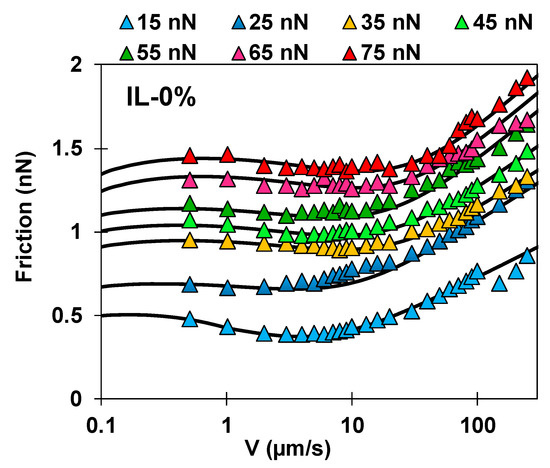
Figure 5.
Comparison between calculated (lines) and measured friction force (symbols) as a function of the velocity for IL-0%. Figures S5 and S6 in the SI show the results for IL-44% and PEG-IL.
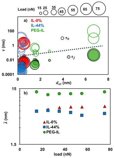
Figure 6.
Fitting parameters of the molecular friction model for the three investigated systems: IL-0% (red), IL-44% (blue) and PEG-IL (green). (a) Boundary-film lubrication. Bubble diagram with characteristic times of bond formation (full bubbles) and rupture (empty bubbles) on the Y-axis and length of the elastic junctions () on the X-axis. The increasing size of the bubble indicates the increasing load from 15 to 75 nN. (b) Hydrodynamic lubrication. Characteristic length estimated from the activation volume () as a function of the load.

Table 1.
Physical parameters of the elastic-viscous friction model for the selected model systems at two loads 15 and 75 nN: = characteristic times of bond formation, = characteristic times of bond rupture, = critical stretching length, = shear modulus, = junction length, = Eyring’s stress.
In IL-0%, the relaxation time for bond formation decreases significantly with load (~0.04–0.005 ms, 0.13–0.11 nm, ~0.55 nm), which is understood as the effect of confinement in favoring the interionic interactions across the slip plane [46], thereby justifying the increase in friction with load. The characteristic time for bond rupture remains approximately constant and equal to ~ 2–3 ms. The presence of water in IL-44% significantly decreases the characteristic time for bond reformation () to less than 0.004 ms, thereby eliminating the velocity-weakening effect observed in the dry IL and extending the plateau over a wider range of sliding velocities; water thus favors the intermolecular interactions across the slip plane. The smaller in IL-44% than in IL-0% could promote a decrease in friction with decrease in velocity, but the required slow velocities were not attained in our experiments. While there is no significant difference in the stretching length () of the junctions in dry and wet IL, the best fit to the experimental results is achieved in IL-44% by assuming that significantly decreases with applied load from 0.55 to 0.26 nm; the latter is also close to the diameter of a water molecule. This agrees with previous experimental works [13,14] and simulations [33] showing that the presence of water facilitates the squeeze-out of the IL and leads to thinner films under the same applied loads, in which water is present. The significant increase in friction in IL-44% is thus mainly associated to the much thinner films under confinement, which lead to higher (stretching) elastic force per junction, .
On the brush-coated mica solvated by the dry IL, the prominent transition of the fitting parameters from 55 to 65 nN must originate from the change of the lubrication mechanism. Here, jumps from 0.002 to 0.050 ms, increases from 0.5 to 10 ms, ~ from 0.1 to ~ 1 nm and from 1.5 to 6.70 nm. Although the analysis of the measured stick-slip will be reported in a separate work, it is worth mentioning that remarkable stick-slip friction was measured at the highest loads in this model system. Intuitively, the change of behavior can be reconciled by considering that the polymer is strongly compressed at this high load (65 nN ~ 26 mN/m in Figure 1a) and most of the liquid is squeezed out, so that the PEG chains adhere to the colloid due to electrostatic and van der Waals interactions. These “polymer-based” junctions exhibit a longer length (), longer stretching length () and longer characteristic times ( and ) than the “ion” junctions, which is consistent with the slower relaxation dynamics of polymers [47]. At loads smaller than 65 nN, in contrast, the slip plane is likely located within the liquid film that separates the brush and the colloid, and thus, the ions play a key role in the sliding process. Despite this, the features of the activated slip in PEG-IL differ from those in IL-0% on bare mica, as shown in Figure 6a. The observed reduction of the characteristic times of bond formation and rupture might rely on the more disordered state of the ions when confined between the colloid and the polymer brush, compared to the uncoated (and charged) mica surface. The “ion” junctions appear “softer” ( MPa) and “longer” (1.5 nm) than in IL-0%, which suggests that either the ion junctions have a different structure in the presence of the polymer, or perhaps both the ions and the polymer determine these junctions. Nonetheless, the properties of these junctions in PEG-IL allow to reduce friction so that the smallest values of friction in the boundary-film lubrication regime are achieved in this system.
At sliding velocities above , friction is mainly originated by the viscous shear of the confined fluid. The viscosity cannot be unambiguously determined from the fit of Equations (1)–(3) to the experimental results because the thickness of the confined fluid film () is unknown. However, both the Eyring’s stress and can be unambiguously estimated. The Eyring’s stress is inversely proportional to the shear-activation length according to , and being the molecular size (~0.7 nm) projected on the slip plane and the shear-activation length. The activation length gives the relative displacement of a molecule (relative to the neighbor layers) every time it passes over an energy barrier. Using = 0.7 nm leads to an activation length that is almost two orders of magnitude larger than expected. We believe that this originates from the slow dynamics of liquids under nanoconfinement (i.e., high viscosity), which has been interpreted as a collective motion of the molecules [48] (ions in our case), and therefore and cannot be equated to the molecular size. Based on this phenomenon, the activation volume under nanoconfinement can be much larger than the molecular volume. Figure 6b shows the estimated values for the average length as a function of the load.
An increase in the activation volume reflects either a larger activation length characteristic of a higher molecular mobility, a larger domain size due to collective motion, or a combination of both. For IL-0%, ranges between 5.9 and 7.3 nm with increase in load (Figure 6b). This may result from the enhanced collective motion of the ions with an increase in pressure. The effect of water on is negligible at the smallest loads. The activation volume in IL-44% decreases only slightly with an increase in load, which may result from the more significant effect of water on disturbing the structure of the ionic liquid and/or from the decrease in mobility due to the increase in pressure. We note that Equation (3) did not provide a good fit to the viscous component of friction in IL-44% at loads higher than 45 nN (see Figure S5). It is possible that the increase in the relative concentration of water in the thinner films (as observed in MD simulations [33] and proposed in various experimental works [24,49,50]) is responsible for a prominent shear-thinning behavior. Here, high shear rates could partially destroy the structure of the confined fluid, which would result in a smaller activation volume, but further work is needed to clarify these results.
The largest -values (~11 to 13 nm) are obtained for PEG-IL. The increase in with load suggests, also here, that the collective motion is promoted with an increase in pressure. Although the polymer can contribute to the large molecular size, this effect cannot be quantified at this point. However, a dilation or hydrodynamic lift has been often proposed for similar brush systems with other solvents [51,52,53]. This common assumption implies a reduction of the polymer concentration in the confined film so that the IL that solvates the brush mainly dictates the viscous dissipation and the sliding process at high sliding velocities, [54,55] like in IL-0% and IL-44%. The presence of the polymer seems to promote the disorder of the IL, as discussed earlier. Therefore, the larger -values for PEG-IL compared to the dry IL on uncoated mica might indicate that the ions are more mobile in the presence of PEG-brushes. This would also imply a lower viscosity according to Eyring [20] and explain the lower friction measured for this system.
4. Conclusions and Implications
The proposed friction model provides a molecular perspective for IL lubrication of smooth contacts by considering the stress-activated motion of layers of liquid molecules during the sliding process. The variation of friction with velocity indicates the action of two different lubrication mechanisms, which are associated to boundary-film (described as the activated slip of boundary layers) and hydrodynamic lubrication (described as the activated flow of the confined film).
A comparison of the three selected model systems (dry IL, IL equilibrated with humid air and PEG brush solvated by the dry IL) has allowed us to identify the properties that control friction. Water is ubiquitously present in the environment and in most of the ILs, and several works have demonstrated its influence on the interfacial structure and lubricity of ILs (see recent review in Ref. [5]). The presence of water molecules in IL-44% (a moderately hydrophobic IL) facilitates the squeeze-out of the ions-so that films of smaller thickness compared to IL-0% are achieved under the same contact stress-and strengthens the interactions at the slip plane-perhaps as a result of the hydrogen bonding between the ions and the water molecules, and both phenomena are associated with the significant increase in friction. It is to be noted that the failure of the model to describe the shear thinning behavior in IL-44% at the highest applied loads is very likely associated to the increasing interfacial concentration of water as the film thickness decreases, but this still requires more investigation. Our ongoing work is focused on providing a direct measure of the dilation of the films and of the viscosity, which will complement these conclusions.
The faster bond dynamics and weaker interactions across the slip plane on brush-coated surfaces compared to the bare surface may be associated to the more disordered state of the ions at the polymer-liquid interface [46]; an analogous conclusion can be drawn from the large activation volume of the liquid film confined between brush-coated surfaces. One lesson learned is that maintaining the fluidity of the IL under strong confinement appears to be beneficial for lubrication. Our previous work demonstrated that the PEG chains preferentially interact with the cation, which positively charges the brush and yields a higher osmotic pressure and a much stronger brush stretching than in aqueous solutions [26]. While brush-bearing surfaces appear as an outstanding strategy to achieve lower friction in lubricated contacts with ILs, the efficient lubrication is limited by the de-solvation of the polymer upon a high compression and slow sliding velocities [56,57]. Stronger interactions between the polymer and the IL would maintain the lubricious behavior under more severe loading conditions; this calls for more research on the solvation of polymers and polymer brushes by ILs.
Finally, this work also has implications for the molecular design of efficient lubricants. Ionic liquids that order with more difficulty, e.g., due to the incommensurate molecular structures of the ions, less ability to hydrogen-bond and less localized charge, could reduce the strength of the intermolecular interactions and facilitate the rupture of bonds across the slip plane, all of which should favor a decrease in friction in the boundary-film lubrication regime. The relation between molecular structure and viscosity is intricate, especially under confinement, and therefore, additional strategies to maintain the fluidity of the liquid are necessary, e.g., using IL as additives to low-viscosity oils [58,59,60]. We recognize that these conclusions and implications are based on a simplified analytical friction model, while more sophisticated numerical simulations that account for bond dynamics in other systems have been recently reported [61]. Such numerical models are potentially applicable to predict friction at contacts lubricated with ILs, which should enable more precise comparisons of the effect of molecular features on friction in the future.
5. Materials and Methods
A volume of 200 µL of 1-ethyl-3-methyl imidazolium bis-(trifluoromethylsulfonyl) imide (Iolitec, Heilbronn, Germany, 99% purity, abbreviated [EMIM][TFSI]) was dried in vacuo at 50 °C before use (abbreviated as IL-0%). For the second set of experiments, 200 µL of the dry ionic liquid (IL) were stored in a sealed chamber at constant 44% RH (abbreviated as IL-44%). The water content in [EMIM][TFSI] was determined gravimetrically to be 0.5 wt % (10 mol %) in equilibrium. The copolymer poly(l-lysine)-graft-poly(ethylene glycol)-abbreviated as PLL-g-PEG-with molecular weights of the PLL backbone and of the PEG chains of 20 and 5 kDa, respectively, and a grafting ratio of 3.5, was purchased from SuSoS AG (Dübendorf, Switzerland). The contour length of PEG (5 kDa) is ~39.5 nm, estimated for a polymerization degree of n = 113 and monomer size a = 0.35 nm. The polymer solutions were prepared by dissolving 0.15 mg of PLL-g-PEG in 0.5 mL of dry [EMIM][TFSI]. The solution was stirred under N2 gas for 2 days at 50 °C, which was found to lead to complete dissolution of the copolymer.
Lateral and normal force measurements were conducted on an Atomic Force Microscope (JPK Nanowizard Ultra, JPK Instruments, Berlin, Germany). A silica colloid (diameter = 5 µm) was glued to a tip-less cantilever (nominal spring constant = 1.5 N/m, CSC37-No Al/tipless, MikroMasch, Watsonville, CA, USA). Before attaching the colloids, the normal stiffness of the cantilevers was determined by the thermal noise method and the lateral stiffness was obtained by means of Sader’s method [62]. The AFM cantilevers with the glue spheres were cleaned in an ethanol bath followed by UV ozone for 30 min just before the AFM experiment. Root-mean-square (RMS) roughness of each silica colloid within the area of contact was determined via reverse imaging using a clean test grating (MikroMasch, Watsonville, CA, USA). Colloids were only used when the RMS roughness was smaller than 2 nm in an area of 200 nm × 200 nm, larger than the calculated contact area of the colloid with the polymer brush and with the mica surface.
The dry IL was directly transferred to a flow cell that enclosed a freshly cleaved mica surface. The cell was continuously purged with N2 before the injection of the liquid and during the force measurements, to hinder water uptake. For the experiments with IL-44%, the equilibrated liquid at 44%RH was injected into the airtight cell containing the mica surface equilibrated with laboratory air. The polymer solution was injected onto a freshly cleaved mica surface that had been stored in an airtight chamber filled with dry N2 gas. 24 h were given for the polymer to adsorb onto the mica surface in the dry environment. Details about the properties of the polymer brush in [EMIM][TFSI] (abbreviated as PEG-IL) can be found in our previous work [26].
Lateral force measurements were conducted with the same colloid as a function of the sliding velocity ranging between 0.5 and 250 µm/s at normal loads between 15 and 75 nN, respectively, and with a constant sliding distance of 10 µm. Load-dependent friction-force measurements were performed at 1 µm/s. The load was varied between 5 and 75 nN. In each experiment, the normal load was first gradually increased (loading curves), and it was subsequently decreased (unloading curves) to verify the reproducibility of the load-dependent friction force and to identify possible structural changes. At least eight lateral force loops were measured at each load and velocity by recording the lateral deflection of the cantilever tip in the forward (trace) and reverse (retrace) directions. The friction force in a loop was calculated by averaging over the half width of the trace and retrace scans. Normal surface forces were measured by colloidal probe AFM on the same samples where friction was measured. To avoid any perturbation of the interfacial structure, the velocity of approach to and separation from the surface was selected to be 20 nm/s.
The surface-adsorbed polymer was imaged after each friction test by QITM imaging. Here, each pixel of an image (500 nm by 500 nm) results from a force-distance curve at the corresponding location. Silicon tips (CSC37-No Al, MikroMasch, spring constants 0.3 N/m, nominal radii ~ 10 nm) were used for QITM imaging. Each force curve was measured with a tip velocity of 1.5 µm/s and a set point of 2 nN. The force-distance curves were then combined and analyzed to generate an image.
An extended SFA [63,64,65] was used to measure the surface forces between bare and brush-bearing mica surfaces in the selected ILs to provide more insight into the interfacial structure. In our SFA, fast spectral correlation is employed to analyze the interference pattern of the transmitted white light through the two atomically flat mica surfaces confining the IL, which enables to simultaneously determine the gap distance and the refractive index [63,64]. The mica surfaces were prepared following a well-established protocol [26]. Then, they were glued to cylindrical glass lenses and placed in the SFA fluid cell with perpendicular cylindrical axes, while the cell was continuously purged with dry N2 to keep the mica surfaces as dry as possible. A 200 µL-droplet of vacuum-dried IL either neat or with the dissolved copolymer was carefully located in the gap between the mica surfaces using a syringe. One day was allowed for the copolymer to adsorb onto the surfaces in a dry N2 environment and at 25 °C prior to the force measurements. Force-distance curves were measured by approaching/separating the surfaces at a constant speed of 0.5 nm/s. All measurements were conducted at 25 °C while the solution was kept dry by continuously purging the SFA cell with dry N2 gas. For the experiments with IL-44%, the SFA cell was equilibrated with laboratory air.
Supplementary Materials
The following data are available online at http://www.mdpi.com/2075-4442/6/3/64/s1. Figure S1: Representative force-distance curves measured by colloidal probe AFM. Figure S2: QI images obtained with a silicon sharp tip on PEG-bearing mica surface in dry [EMIM][TFSI]. Figure S3: Transition velocity (V*) and value of the friction force at V*. Figure S4: Friction force normalized by the friction value as a function of . Figure S5: Comparison between calculated and measured friction force as a function of the velocity for IL-44%. Figure S6: Comparison between and measured friction force as a function of the velocity for the polymer brush solvated by the dry ionic liquid (PEG-IL).
Author Contributions
Conceptualization, R.M.E.M.; Methodology, M.H. and R.M.E.M.; Formal Analysis, M.H. and R.M.E.M.; Investigation, M.H.; Writing-Original Draft Preparation, M.H. and R.M.E.M.; Writing-Review & Editing, R.M.E.M.; Supervision, R.M.E.M.
Funding
We acknowledge the funding provided by the Research Board at the University of Illinois at Urbana-Champaign (Award RB18042).
Acknowledgments
The authors thank W.T. (Eddy) Tysoe for fruitful discussions and for his inspiring lecture in the 255th ACS National Meeting in New Orleans (2018) in the symposium of Tribochemistry and Mechanochemistry, which motivated us to review friction models suitable for ionic liquids.
Conflicts of Interest
The authors declare no conflict of interest.
References
- Armand, M.; Endres, F.; MacFarlane, D.R.; Ohno, H.; Scrosati, B. Ionic-Liquid Materials for the Electrochemical Challenges of the Future. Nat. Mater. 2009, 8, 621–629. [Google Scholar] [CrossRef] [PubMed]
- Weingärtner, H. Understanding Ionic Liquids at the Molecular Level: Facts, Problems, and Controversies. Angew. Chem. Int. Ed. 2008, 47, 654–670. [Google Scholar] [CrossRef] [PubMed]
- Liu, H.; Liu, Y.; Li, J. Ionic Liquids in Surface Electrochemistry. Phys. Chem. Chem. Phys. 2010, 12, 1685–1697. [Google Scholar] [CrossRef] [PubMed]
- Hayes, R.; Wakeham, D.; Atkin, R. Interfaces of Ionic Liquids (2). In Ionic Liquids Uncoiled; John Wiley & Sons, Inc.: New York, NY, USA, 2012; pp. 51–85. [Google Scholar]
- Espinosa-Marzal, R.M.; Han, M.; Arcifa, A.; Spencer, N.D.; Rossi, A. Ionic Liquids at Interfaces and Their Tribological Behavior. In Reference Module in Chemistry, Molecular Sciences and Chemical Engineering; Wandelt, K., Ed.; Elsevier: Oxford, UK, 2017; pp. 172–194. [Google Scholar]
- Fajardo, O.Y.; Bresme, F.; Kornyshev, A.A.; Urbakh, M. Electrotunable Lubricity with Ionic Liquid Nanoscale Films. Sci. Rep. 2015, 5, 7698. [Google Scholar] [CrossRef] [PubMed]
- Sweeney, J.; Hausen, F.; Hayes, R.; Webber, G.B.; Endres, F.; Rutland, M.W.; Bennewitz, R.; Atkin, R. Control of Nanoscale Friction on Gold in an Ionic Liquid by a Potential-Dependent Ionic Lubricant Layer. Phys. Rev. Lett. 2012, 109, 155502. [Google Scholar] [CrossRef] [PubMed]
- Ye, C.; Liu, W.; Chen, Y.; Yu, L. Room-Temperature Ionic Liquids: A Novel Versatile Lubricant. Chem. Commun. 2001, 2244–2245. [Google Scholar] [CrossRef]
- Perkin, S.; Albrecht, T.; Klein, J. Layering and Shear Properties of an Ionic Liquid, 1-Ethyl-3-Methylimidazolium Ethylsulfate, Confined to Nano-Films between Mica Surfaces. Phys. Chem. Chem. Phys. 2010, 12, 1243–1247. [Google Scholar] [CrossRef] [PubMed]
- Werzer, O.; Cranston, E.D.; Warr, G.G.; Atkin, R.; Rutland, M.W. Ionic Liquid Nanotribology: Mica-Silica Interactions in Ethylammonium Nitrate. Phys. Chem. Chem. Phys. 2012, 14, 5147–5152. [Google Scholar] [CrossRef] [PubMed]
- Li, H.; Rutland, M.W.; Atkin, R. Ionic Liquid Lubrication: Influence of Ion Structure, Surface Potential and Sliding Velocity. Phys. Chem. Chem. Phys. 2013, 15, 14616–14623. [Google Scholar] [CrossRef] [PubMed]
- Smith, A.M.; Lovelock, K.R.; Gosvami, N.N.; Welton, T.; Perkin, S. Quantized Friction across Ionic Liquid Thin Films. Phys. Chem. Chem. Phys. 2013, 15, 15317–15320. [Google Scholar] [CrossRef] [PubMed]
- Espinosa-Marzal, R.M.; Arcifa, A.; Rossi, A.; Spencer, N.D. Microslips to “Avalanches” in Confined, Molecular Layers of Ionic Liquids. J. Phys. Chem. Lett. 2014, 5, 179–184. [Google Scholar] [CrossRef] [PubMed]
- Espinosa-Marzal, R.M.; Arcifa, A.; Rossi, A.; Spencer, N.D. Ionic Liquids Confined in Hydrophilic Nanocontacts: Structure and Lubricity in the Presence of Water. J. Phys. Chem. C 2014, 118, 6491–6503. [Google Scholar] [CrossRef]
- Sweeney, J.; Webber, G.B.; Rutland, M.W.; Atkin, R. Effect of Ion Structure on Nanoscale Friction in Protic Ionic Liquids. Phys. Chem. Chem. Phys. 2014, 16, 16651–16658. [Google Scholar] [CrossRef] [PubMed]
- Arcifa, A.; Rossi, A.; Espinosa-Marzal, R.M.; Spencer, N.D. Influence of Environmental Humidity on the Wear and Friction of a Silica/Silicon Tribopair Lubricated with a Hydrophilic Ionic Liquid. Acs. Appl. Mater. Interfaces 2016, 8, 2961–2973. [Google Scholar] [CrossRef] [PubMed]
- Li, H.; Wood, R.J.; Rutland, M.W.; Atkin, R. An Ionic Liquid Lubricant Enables Superlubricity to Be “Switched on” in Situ Using an Electrical Potential. Chem. Commun. 2014, 50, 4368–4370. [Google Scholar] [CrossRef] [PubMed]
- Eyring, H. The Activated Complex in Chemical Reactions. J. Chem. Phys. 1935, 3, 107–115. [Google Scholar] [CrossRef]
- Eyring, H. Viscosity, Plasticity, and Diffusion as Examples of Absolute Reaction Rates. J. Chem. Phys. 1936, 4, 283–291. [Google Scholar] [CrossRef]
- Spikes, H.; Tysoe, W. On the Commonality between Theoretical Models for Fluid and Solid Friction, Wear and Tribochemistry. Tribol. Lett. 2015, 59, 21. [Google Scholar] [CrossRef]
- Briscoe, B.; Evans, D. The Shear Properties of Langmuir-Blodgett Layers; The Royal Society: Cambridge, UK, 1982; pp. 389–407. [Google Scholar]
- Schallamach, A. A Theory of Dynamic Rubber Friction. Wear 1963, 6, 375–382. [Google Scholar] [CrossRef]
- Drummond, C.; Israelachvili, J.; Richetti, P. Friction between Two Weakly Adhering Boundary Lubricated Surfaces in Water. Phys. Rev. E 2003, 67, 066110. [Google Scholar] [CrossRef] [PubMed]
- Cheng, H.W.; Stock, P.; Moeremans, B.; Baimpos, T.; Banquy, X.; Renner, F.U.; Valtiner, M. Characterizing the Influence of Water on Charging and Layering at Electrified Ionic-Liquid/Solid Interfaces. Adv. Mater. Interfaces 2015, 2, 150159. [Google Scholar] [CrossRef]
- Arcifa, A.; Rossi, A.; Ramakrishna, S.N.; Espinosa-Marzal, R.; Sheehan, A.; Spencer, N.D. Lubrication of Si-Based Tribopairs with a Hydrophobic Ionic Liquid: The Multiscale Influence of Water. J. Phys. Chem. C 2018, 122, 7331–7343. [Google Scholar] [CrossRef]
- Han, M.; Espinosa-Marzal, R.M. Strong Stretching of Poly(Ethylene Glycol) Brushes Mediated by Ionic Liquid Solvation. J. Phys. Chem. Lett. 2017, 8, 3954–3960. [Google Scholar] [CrossRef] [PubMed]
- Gebbie, M.A.; Valtiner, M.; Banquy, X.; Fox, E.T.; Henderson, W.A.; Israelachvili, J.N. Ionic Liquids Behave as Dilute Electrolyte Solutions. Proc. Natl. Acad. Sci. USA 2013, 110, 9674–9679. [Google Scholar] [CrossRef] [PubMed]
- Gebbie, M.A.; Smith, A.M.; Dobbs, H.A.; Lee, A.A.; Warr, G.G.; Banquy, X.; Valtiner, M.; Rutland, M.W.; Israelachvili, J.N.; Perkin, S.; et al. Long Range Electrostatic Forces in Ionic Liquids. Chem. Commun. 2017, 53, 1214–1224. [Google Scholar] [CrossRef] [PubMed]
- Horn, R.G.; Evans, D.F.; Ninham, B.W. Double-Layer and Solvation Forces Measured in a Molten-Salt and Its Mixtures with Water. J. Phys. Chem. 1988, 92, 3531–3537. [Google Scholar] [CrossRef]
- Atkin, R.; Warr, G.G. Structure in Confined Room-Temperature Ionic Liquids. J. Phys. Chem. C 2007, 111, 5162–5168. [Google Scholar] [CrossRef]
- Lhermerout, R.; Perkin, S. Nanoconfined Ionic Liquids: Disentangling Electrostatic and Viscous Forces. Phys. Rev. Fluids 2018, 3, 014201. [Google Scholar] [CrossRef]
- Zhou, H.; Rouha, M.; Feng, G.; Lee, S.S.; Docherty, H.; Fenter, P.; Cummings, P.T.; Fulvio, P.F.; Dai, S.; McDonough, J.; et al. Nanoscale Perturbations of Room Temperature Ionic Liquid Structure at Charged and Uncharged Interfaces. ACS Nano 2012, 6, 9818–9827. [Google Scholar] [CrossRef] [PubMed]
- Fajardo, O.Y.; Bresme, F.; Kornyshev, A.A.; Urbakh, M. Water in Ionic Liquid Lubricants: Friend and Foe. ACS Nano 2017, 11, 6825–6831. [Google Scholar] [CrossRef] [PubMed]
- Asai, H.; Fujii, K.; Nishi, K.; Sakai, T.; Ohara, K.; Umebayashi, Y.; Shibayama, M. Solvation Structure of Poly(Ethylene Glycol) in Ionic Liquids Studied by High-Energy X-Ray Diffraction and Molecular Dynamics Simulations. Macromolecules 2013, 46, 2369–2375. [Google Scholar] [CrossRef]
- Costa, L.T.; Ribeiro, M.C. Molecular Dynamics Simulation of Polymer Electrolytes Based on Poly(Ethylene Oxide) and Ionic Liquids. Ii. Dynamical Properties. J. Chem. Phys. 2007, 127, 164901. [Google Scholar] [CrossRef] [PubMed]
- Israelachvili, J.N. Intermolecular and Surface Forces, 3rd ed.; Elsevier Science: Amsterdam, The Netherland, 2011. [Google Scholar]
- Shoaib, T.; Heintz, J.; Lopez-Berganza, J.A.; Muro-Barrios, R.; Egner, S.A.; Espinosa-Marzal, R.M. Stick-Slip Friction Reveals Hydrogel Lubrication Mechanisms. Langmuir 2018, 34, 756–765. [Google Scholar] [CrossRef] [PubMed]
- Rosenberg, K.J.; Goren, T.; Crockett, R.; Spencer, N.D. Load-Induced Transitions in the Lubricity of Adsorbed Poly(l-Lysine)-G-Dextran as a Function of Polysaccharide Chain Density. ACS Appl. Mater. Interfaces 2011, 3, 3020–3025. [Google Scholar] [CrossRef] [PubMed]
- Iler, R.K. The Chemistry of Silica; Wiley: New York, NY, USA, 1979. [Google Scholar]
- He, Z.; Alexandridis, P. Nanoparticles in Ionic Liquids: Interactions and Organization. Phys. Chem. Chem. Phys. 2015, 17, 18238–18261. [Google Scholar] [CrossRef] [PubMed]
- Esfahanian, M.; Hamrock, B.J. Fluid-Film Lubrication Regimes Revisited. Tribol. Trans. 1991, 34, 628–632. [Google Scholar] [CrossRef]
- Johnson, K.L.; Tevaarwerk, J.L. Shear Behavior of Elastohydrodynamic Oil Films. Proc. R. Soc. Lond. Ser. A 1977, 356, 215–236. [Google Scholar] [CrossRef]
- Bair, S.; Martinie, L.; Vergne, P. Classical Ehl Versus Quantitative Ehl: A Perspective Part Ii-Super-Arrhenius Piezoviscosity, an Essential Component of Elastohydrodynamic Friction Missing from Classical Ehl. Tribol. Lett. 2016, 63, 37. [Google Scholar] [CrossRef]
- O’neill, M.; Stewartson, K. On the Slow Motion of a Sphere Parallel to a Nearby Plane Wall. J. Fluid Mech. 1967, 27, 705–724. [Google Scholar] [CrossRef]
- Grest, G.S. Interfacial Sliding of Polymer Brushes: A Molecular Dynamics Simulation. Phys. Rev. Lett. 1996, 76, 4979–4982. [Google Scholar] [CrossRef] [PubMed]
- Hu, H.W.; Carson, G.A.; Granick, S. Relaxation Time of Confined Liquids under Shear. Phys. Rev. Lett. 1991, 66, 2758–2761. [Google Scholar] [CrossRef] [PubMed]
- Rubinstein, M.; Colby, R.H. Polymer Physics; OUP: Oxford, UK, 2003. [Google Scholar]
- Granick, S. Motions and Relaxations of Confined Liquids. Science 1991, 253, 1374–1379. [Google Scholar] [CrossRef] [PubMed]
- Feng, G.; Jiang, X.; Qiao, R.; Kornyshev, A.A. Water in Ionic Liquids at Electrified Interfaces: The Anatomy of Electrosorption. ACS Nano 2014, 8, 11685–11694. [Google Scholar] [CrossRef] [PubMed]
- Zhang, F.; Fang, C.; Qiao, R. Effects of Water on Mica-Ionic Liquid Interfaces. J. Phys. Chem. C 2018, 122, 9035–9045. [Google Scholar] [CrossRef]
- Lemaitre, A. Rearrangements and Dilatancy for Sheared Dense Materials. Phys. Rev. Lett. 2002, 89, 195503. [Google Scholar] [CrossRef] [PubMed]
- Grest, G.S. Computer Simulations of Shear and Friction between Polymer Brushes. Curr. Opin. Colloid Interfaces Sci. 1997, 2, 271–277. [Google Scholar] [CrossRef]
- Irfachsyad, D.; Tildesley, D.; Malfreyt, P. Dissipative Particle Dynamics Simulation of Grafted Polymer Brushes under Shear. Phys. Chem. Chem. Phys. 2002, 4, 3008–3015. [Google Scholar] [CrossRef]
- Nalam, P.C.; Ramakrishna, S.N.; Espinosa-Marzal, R.M.; Spencer, N.D. Exploring Lubrication Regimes at the Nanoscale: Nanotribological Characterization of Silica and Polymer Brushes in Viscous Solvents. Langmuir 2013, 29, 10149–10158. [Google Scholar] [CrossRef] [PubMed]
- Klein, J.; Perahia, D.; Warburg, S. Forces between Polymer-Bearing Surfaces Undergoing Shear. Nature 1991, 352, 143–145. [Google Scholar] [CrossRef]
- Klein, J.; Kumacheva, E.; Mahalu, D.; Perahia, D.; Fetters, L.J. Reduction of Frictional Forces between Solid-Surfaces Bearing Polymer Brushes. Nature 1994, 370, 634–636. [Google Scholar] [CrossRef]
- Raviv, U.; Giasson, S.; Kampf, N.; Gohy, J.F.; Jerome, R.; Klein, J. Lubrication by Charged Polymers. Nature 2003, 425, 163–165. [Google Scholar] [CrossRef] [PubMed]
- Jimenez, A.E.; Bermudez, M.D. Imidazolium Ionic Liquids as Additives of the Synthetic Ester Propylene Glycol Dioleate in Aluminium-Steel Lubrication. Wear 2008, 265, 787–798. [Google Scholar] [CrossRef]
- Jimenez, A.E.; Bermudez, M.D.; Carrion, F.J.; Martinez-Nicolas, G. Room Temperature Ionic Liquids as Lubricant Additives in Steel-Aluminium Contacts: Influence of Sliding Velocity, Normal Load and Temperature. Wear 2006, 261, 347–359. [Google Scholar] [CrossRef]
- Yu, B.; Bansal, D.G.; Qu, J.; Sun, X.Q.; Luo, H.M.; Dai, S.; Blau, P.J.; Bunting, B.G.; Mordukhovich, G.; Smolenski, D.J. Oil-Miscible and Non-Corrosive Phosphonium-Based Ionic Liquids as Candidate Lubricant Additives. Wear 2012, 289, 58–64. [Google Scholar] [CrossRef]
- Blass, J.; Albrecht, M.; Wenz, G.; Guerra, R.; Urbakh, M.; Bennewitz, R. Multivalent Adhesion and Friction Dynamics Depend on Attachment Flexibility. J. Phys. Chem. C 2017, 121, 15888–15896. [Google Scholar] [CrossRef]
- Cannara, R.J.; Eglin, M.; Carpick, R.W. Lateral Force Calibration in Atomic Force Microscopy: A New Lateral Force Calibration Method and General Guidelines for Optimization. Rev. Sci. Instrum. 2006, 77, 053701. [Google Scholar] [CrossRef]
- Heuberger, M.; Vanicek, J.; Zach, M. The Extended Surface Forces Apparatus. Ii. Precision Temperature Control. Rev. Sci. Instrum. 2001, 72, 3556–3560. [Google Scholar] [CrossRef]
- Heuberger, M. The Extended Surface Forces Apparatus. Part I. Fast Spectral Correlation Interferometry. Rev. Sci. Instrum. 2001, 72, 1700–1707. [Google Scholar] [CrossRef]
- Israelachvili, J.N. Thin Film Studies Using Multiple-Beam Interferometry. J. Colloid Interfaces Sci. 1973, 44, 259–272. [Google Scholar] [CrossRef]


© 2018 by the authors. Licensee MDPI, Basel, Switzerland. This article is an open access article distributed under the terms and conditions of the Creative Commons Attribution (CC BY) license (http://creativecommons.org/licenses/by/4.0/).