Article

Vibration Technologies for Friction Reduction to Overcome Weight Transfer Challenge in Horizontal Wells Using a Multiscale Friction Model

School of Resources and Environment, University of Electronic Science and Technology of China, Chengdu 611731, China
*
Authors to whom correspondence should be addressed.
Lubricants 2018, 6(2), 53; https://doi.org/10.3390/lubricants6020053
Submission received: 27 March 2018 / Revised: 14 May 2018 / Accepted: 17 May 2018 / Published: 29 May 2018
(This article belongs to the Special Issue Oil and Gas Tribology)

Abstract

:
Drag reduction technologies mainly include the mechanical method and the chemical method. Mechanical drag reduction technologies are widespread in the drilling field due to their environmental friendliness and ease of use. Vibration technologies are among some of the most-used mechanical drag reduction technologies. However, various types of vibration tools have the negative effect of obstructing the promotion and application of mechanical drag reduction technologies. This paper widely investigated the types and applications of vibration tools. A drilling agitator system and slider drilling technology were included. The structure and mechanism of the vibration tool were studied. A multiscale friction model was proposed based on the Dahl model according to the drilling environment. The model was verified using experimental data. The multiscale friction model was used to analyze the drag reduction mechanism and the effect of different kinds of vibration technologies. Simulations demonstrated that vibration technologies can effectively reduce the axial friction of the drill string. Longitudinal vibration can reduce the axial friction such that the dependence of the reduced coefficient of friction on the reduced velocity does not change significantly after the reduced oscillation amplitude exceeds the critical value of one. Axial friction decreased with the increasing amplitude of the radial vibration. However, the reduction effect has no relationship with the rate of penetration (ROP). Torsional vibration and rocking motion can reduce the axial friction force. When the oscillation amplitude increases, the axial friction decreases. The reduction effect of slider drilling technology is better than torsional vibration and two other technologies in terms of friction reduction.

Graphical Abstract

1. Introduction

With the trend of unconventional drilling of oil and gas wells, ultra-extend reach wells (u-ERW), and 3D complex geometry wells [1,2], engineers can no longer ignore drilling limitations and weight transfer problems caused by excessive torque and drag [3]. Extreme torque and drag can be detrimental to drilling operations and equipment [4]. Drilling engineers have developed numerous methods to overcome the challenge of these limitations in order to drill further over the years [5]. These methods have included chemical methods and mechanical methods [6]. The chemical methods have been focused on the reduction of the friction factor between drill strings and wellbores [7]. The properties of the mud cake were modified or lubricants were added into the drilling fluid [8]. However, the additives of the lubricants were subject to environmental restrictions and were not cost effective [9]. However, the mechanical methods of reducing the torque and drag were environmentally friendly without the disadvantages of chemical methods. In the mechanical methods of drag reduction, the most widely used mechanical methods have been vibration technologies.
Some articles have described mechanical torque and drag reduction methods in a certain drilling field [10,11], such as an axial oscillation tool. These works promoted the application of vibration technologies in the field. However, a systematic list and analysis of the vibration technologies has not reported regarding the tools’ structure and reduction mechanism. This has hindered the efficient application of mechanical vibration technologies.
This paper attempted to describe the practices and the evolution of the torque and drag mechanical reduction methods. This article consists of the following sections. The first section describes the mechanical vibration reduction technologies at present. The second section proposes a multiscale friction model based on the drilling environment. The third section analyzes the working principal of mechanical vibration technologies on which the friction reduction mechanism is based.

2. Overview of Friction Reduction through Vibration

Although rotary steerable drilling systems (RSS) have made significant inroads as the drilling tools of choice within the last 10 years [12], steerable mud motors with bent housing made up the vast majority of directional drilling projects in the world [13]. For a steerable mud motor, there are two distinct modes: rotary and slide drilling. In the rotary mode, the rotary table is required to rotate. The slide drilling mode, however, brings its own problems. These problems fall mainly into three categories: setting a tool-face after making a connection or coming off the bottom; maintaining the required tool-face orientation while drilling ahead; and transferring enough effective weight to the bit to enable acceptable drilling progress [14]. To overcome these problems, these are two kinds of technology systems that have been widely used in the fields. They are Drilling Agitator Systems and Slider Drilling Technology.

2.1. Drilling Agitator System (DAS)

2.1.1. NOV Hydraulic Oscillation System

The Hydraulic Oscillation System (HOS) was introduced into the market in 2000 and has been used in thousands of runs globally. The HOS is comprised of two tools: the Drilling Agitator Tool (DAT) and the Shock Tool located directly above [14,15], as shown in Figure 1. The DAT is composed of two sections: the power section and the valve and bearing section. The power section is made up of a positive displacement motor driver. The valve and bearing section is composed of an eccentric orifice, driven by the power section, and matched against a concentric orifice, thus generating a continuous wave of pressure pulse as the rotor turns when the drilled mud is pumped through the system [16]. These pressure pulses travel up into the Shock Tool. The Shock Tool mandrel extends as the pressure increases with each pulse, and the disc spring within the Shock Tool causes its mandrel to retract as the pressure drops between pulses. This cyclical extension of the Shock Tool mandrel creates the axial oscillation motion which spreads through the drill string, both above and below the DAS [17]. The type of axial vibration motion is considered to be sine or cosine [10].

2.1.2. Three-Dimensional (3D) Hydraulic Oscillation System

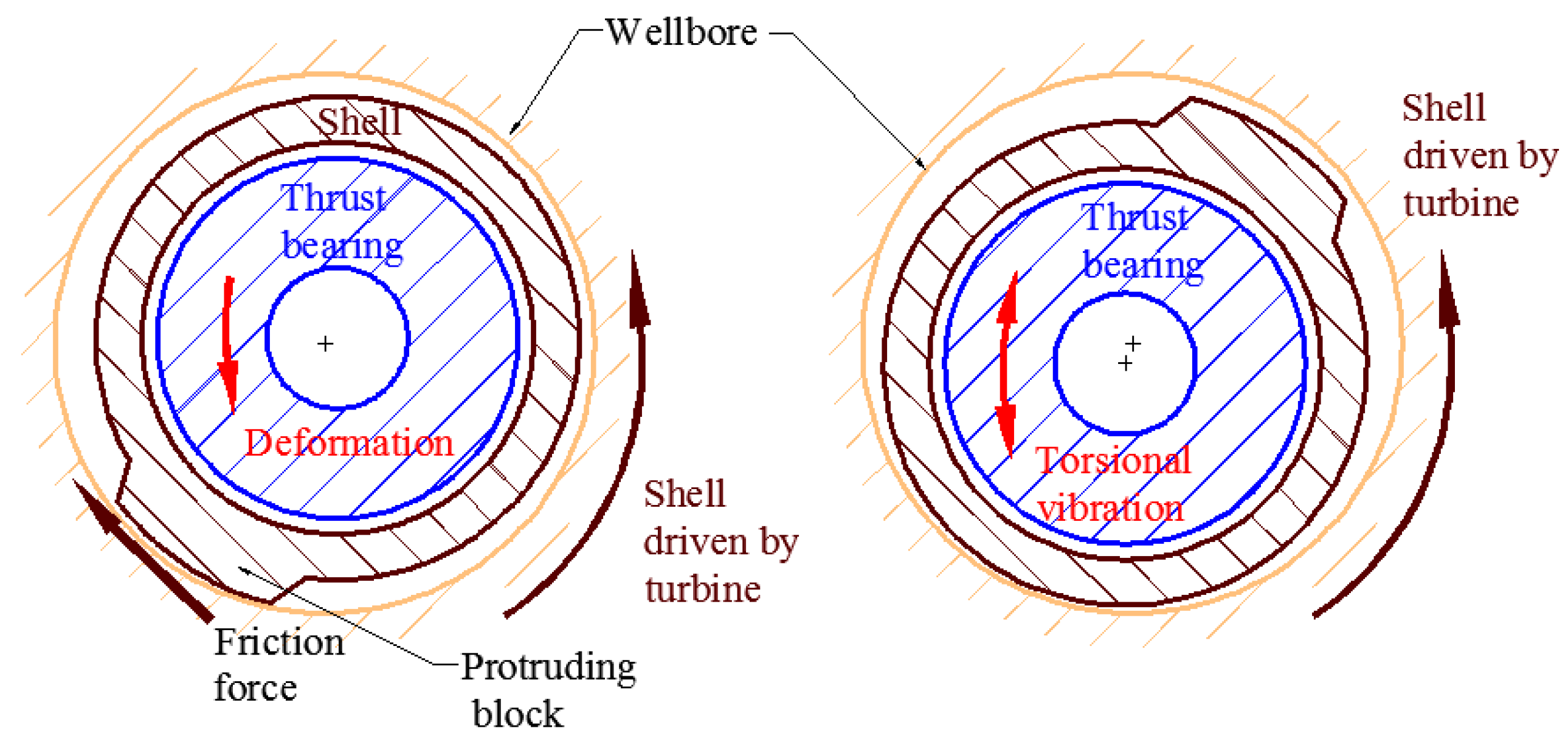
A new type DAS [18] was created that consisted of an adapter sub, clamp sleeve, seal assembly, thrust bearing, adjusting device, alignment bearing, turbines, protruding block inside the shell, separate flow ring, protruding block outside the shell, shell, and main shaft, as presented in the Figure 2.
The 3D Hydraulic Oscillation System could produce axial vibration and torsional vibration at the same time. The generating mechanism of axial vibration was the same as that of the NOV Hydraulic Oscillation System. The torsional vibration was generated by the protruding block inside and outside the shell. The rotating shell was driven by the turbine. The protruding block was rotated with the shell of the tool. When the protruding block was in the low position of the wellbore, it came into contact with the wellbore. Thus, the drilling pipes were rotationally deformed by friction between the protruding block and wellbore. When the protruding block was in the high position, the friction disappeared. The deformation energy was released. The tool and connected drilling pipes generated torsional vibration. The motion velocity of torsional vibration could be considered to be sine or cosine.

2.1.3. Radial Hydraulic Oscillator

Radial hydraulic oscillation is also an important friction reduction tool [19]. It consists of a shell (1), turbine (2), eccentric shaft (3), and bearing (4) [20], as presented in the Figure 3. Its structure involves an eccentric shaft that is driven by the turbines. The rotating eccentric shaft generates a periodic centrifugal force in the vertical direction. The centrifugal force could affect the normal force between the tool and wellbore. It influences the axial friction force of the drilling string. The centrifugal pattern should be sine or cosine according to the working structure of radial hydraulic oscillation.

2.2. Slider Drilling Technology

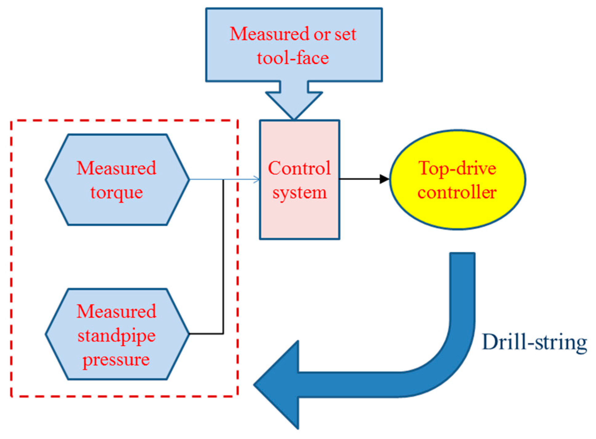
The maintain of the tool-face of the bottom hole assembly was treated as one of the control objectives. The surface torque and stand pipe pressure values were treated as feedback of the Slider Drilling Technology, as presented in the Figure 4. This technology deploys a control system with the top drive controller that automatically rocks the pipes to the right and left. The motion of the drill string was subjected to a rigorous analysis of torque by a computer/software [21,22,23], as it could affect the actual surface torque and standpipe pressure.
Slider Drilling Technology is also called torque rocking drilling. The Slider Drilling System has no downhole parts. So, it was easy to install in the present drill rig.
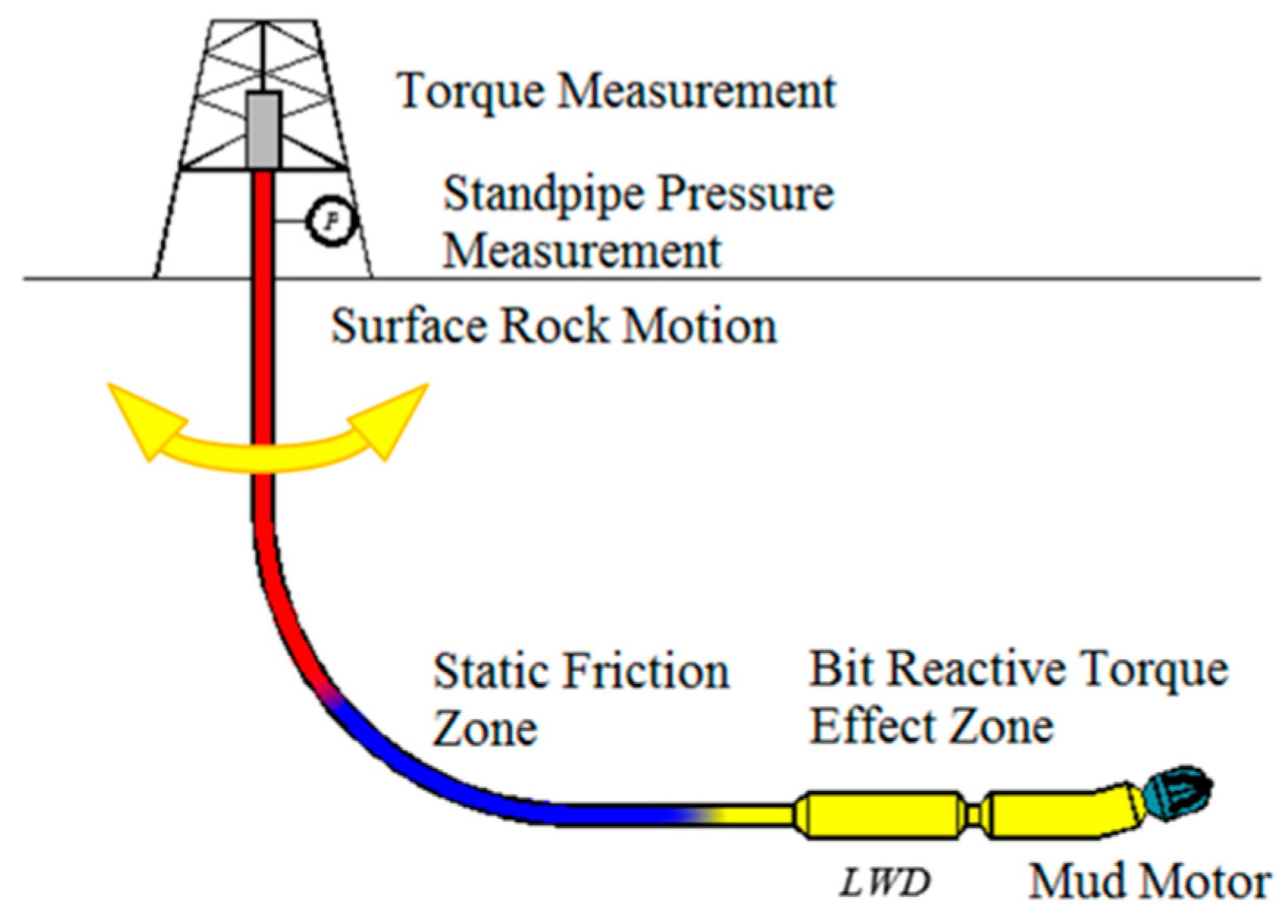
The system works by rotating the top of the drill string, so the upper part of the drill string always experiences tangential motion. The system maintains the drill string friction in the dynamics mode and significantly reduces axial friction [13,23]. However, in the slide drilling mode, it needs to maintain the stability of the tool-face of the steerable mud motor. The rocking motion of the drill string should not affect the bottom hole assembly (BHA). So, there is maximum depth to which a particular applied surface torque can twist the drill string. This depth was determined by a typical torque and drag program [21,24,25]. The actual maximum depth was influenced by the surface maximum clockwise and counterclockwise torque [26]. It was found that the reactive torque of the mud motor was counteracted by the friction of the BHA, as presented in the Figure 5. The friction could keep the tool-face stable. Therefore, there were three zones of the drill string in the slide drilling mode: the surface torque effect zone, the static friction zone, and the bit reactive torque effect zone.

3. Friction Model between Tools and Drill String

3.1. Surface and Contacts Forms

Friction is very complex [27]. The axial friction force (called drag) in the axial direction is a problem demanding attention in drilling engineering. Low axial friction can be beneficial for drilling. During slider drilling or compound drilling, the motion of the drill string is a result of the superposition of two motions. The first of these is the drill string’s tangential motion; the second is the sliding motion in the wellbore’s axial direction.
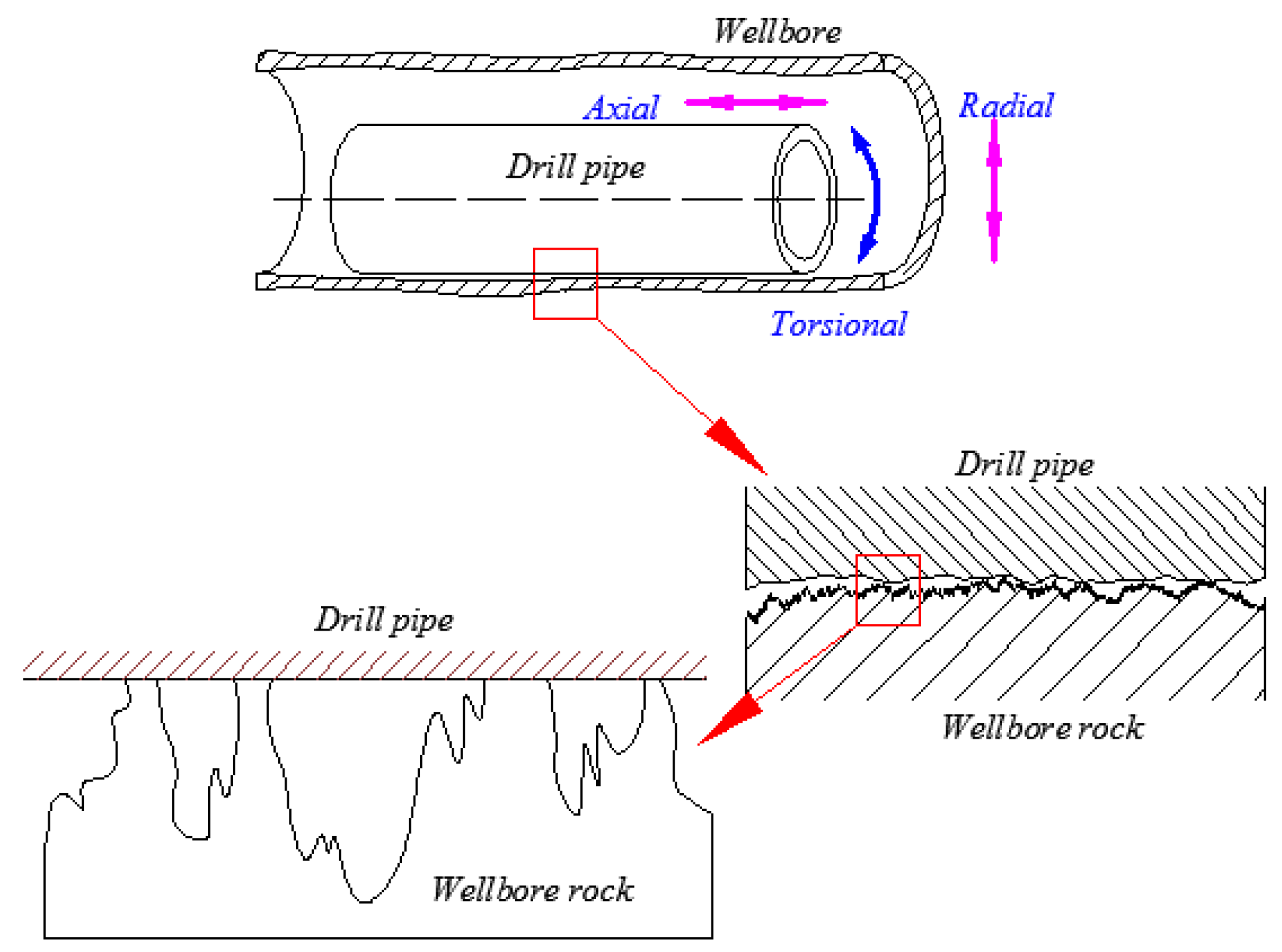
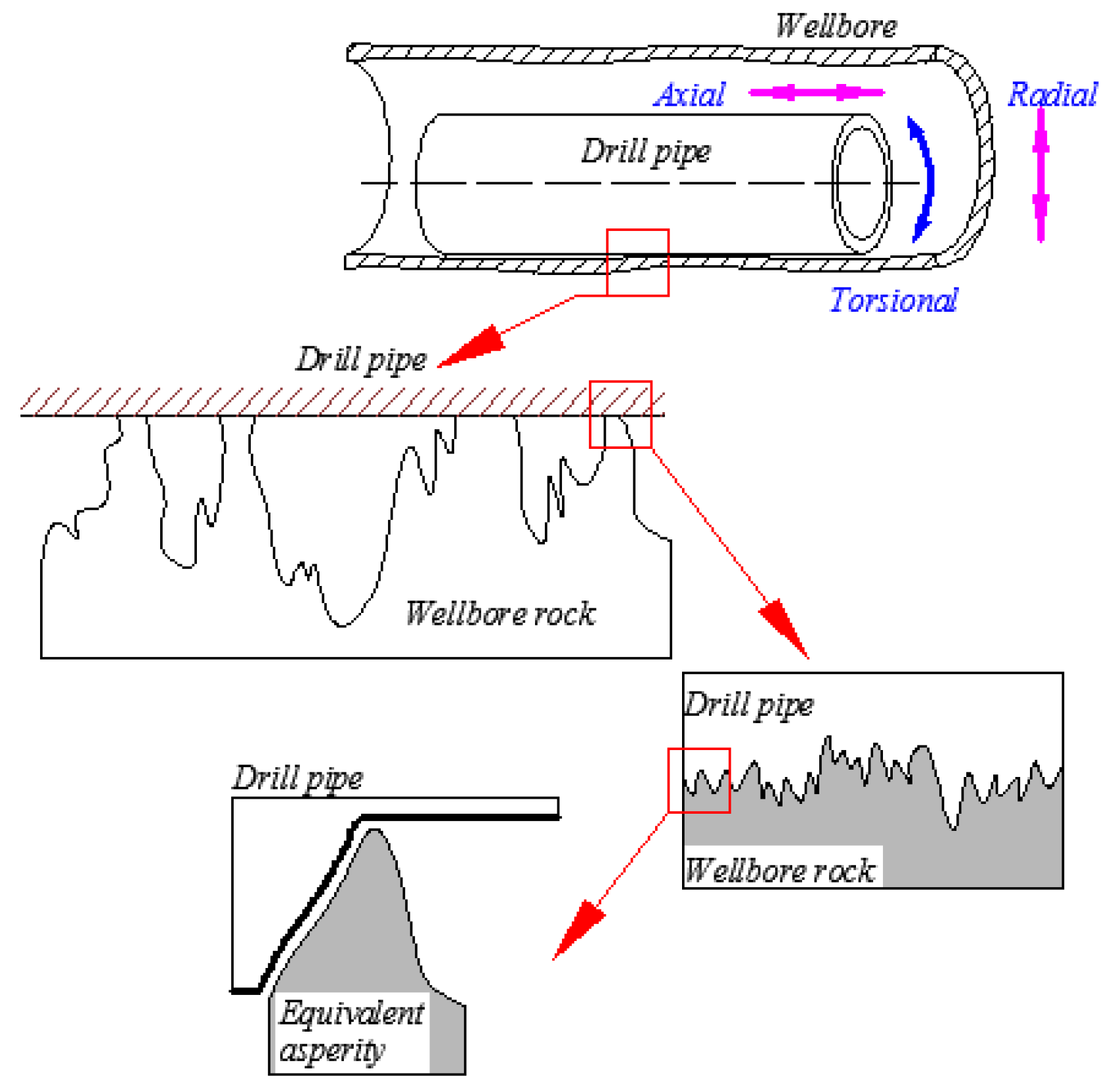
On the macroscopic level, the apparent area of wellbore surfaces observed by the naked eye was “rough” [28]. The drill string surface, apparently a smooth surface, was still “rough” on a microscopic level. The micro-contact models [29,30] assumed that surfaces were composed of hemi-spherically tipped asperities, as presented in the Figure 6. The elastic contact of spheres and half spaces was governed by Hertz equations to compute the load, contact area, and contact pressure acting on a deformed asperity.
Considering the real contact between the drill string and the borehole rock, we made the same assumption for the contact surface as follows. This implies that the drill string had a slightly rough surface and the wellbore presented a severe rough surface composed of a large number of elastic asperities, which was an abstraction of asperities. Due to the roughness and hardness difference between the drill string and wellbore rock at the surface contact, the general elastic asperity in the dynamic friction model should be the same as the asperities on the wellbore, which, unlike in other models, was assumed on the motion body.

3.2. Basic Assumptions

To analyze the real working conditions of a drill string in a down-hole, the following assumptions were made: (1) the asperities on the drill string were rigid; (2) the asperities on the wellbore rock were elastic; (3) rolling of the drill string would not occur.

3.3. Multiscale Friction Model

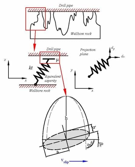
Based on the above assumptions, the drill string’s actual working conditions can be simplified, as shown in the interaction model in Figure 7.
The rough wellbore rock can be simplified as peaks that come into contact with the surface of the drill string. This occurred on the millimeter-scale. The contact area between peaks and the drill string consisted of many asperities. The friction behavior of these asperities is equivalent to that of one asperity, as presented in Figure 7. The equivalent asperity usually occurred on the micrometer-scale.

3.3.1. Asperity Friction Model

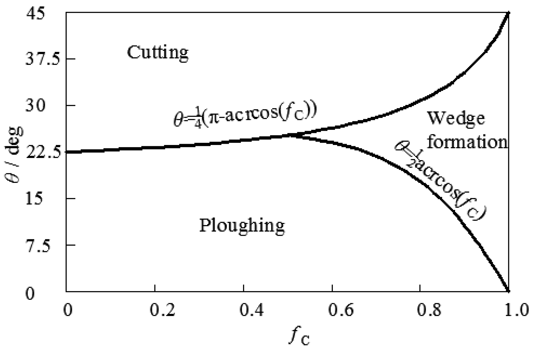
Friction forces acting on individual asperities were described by adopting the contact model of Challen and Oxley [31,32]. This model deduced two-dimensional (2D) slip-line fields, assuming a plane strain deformation state and ideal plastic material behavior. The active model could be determined by so-called wear-model diagrams, as presented in Figure 8. These diagrams describe friction modes as a function of the attack angle of the wedge-shaped asperity θ and the shear factor fC.
The expression for the friction coefficient μ in the cutting regime was given by the Challen and Oxley model [31,32]:
μ c u t t i n g = tan ( θ 1 4 π + 1 2 arccos ( f C ) )
The friction coefficient in the ploughing regime was expressed by the following equation [33,34]:
μ p l o u g h i n g = A 1 s i n θ + cos ( arccos ( f C θ ) ) A 1 s i n θ + sin ( arccos ( f C θ ) )
with:
A 1 = 1 + 1 2 π + arccos ( f C ) 2 θ 2 arcsin ( sin θ ( 1 f C ) 0.5 )
The expression for the friction coefficient in the wedge formation regime was given by:
μ w e a r = { 1 2 sin A 2 + 1 f C 2 } sin θ + f C cos θ { 1 2 sin A 2 + 1 f C 2 } cos θ f C sin θ
with:
A 2 = 1 1 4 π 1 2 arccos ( f C ) + arcsin ( sin θ ( 1 f C ) 0.5 )
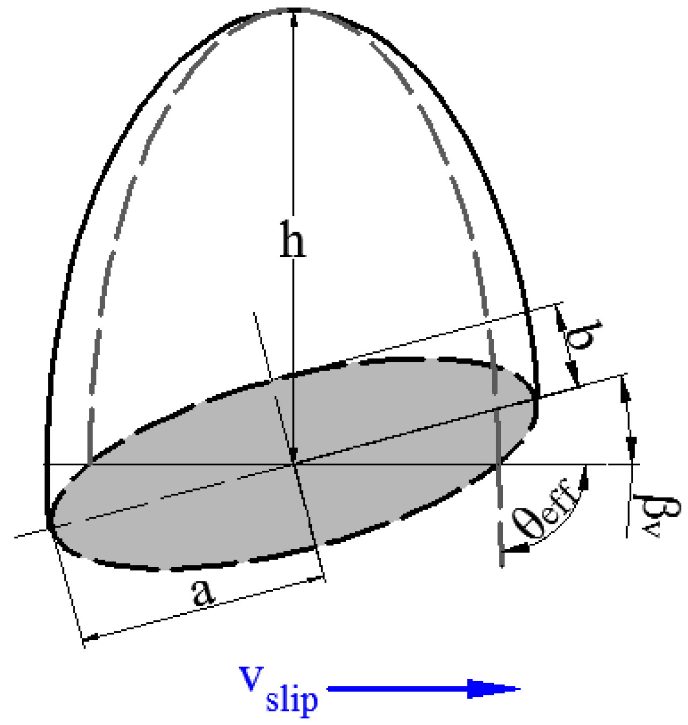
An asperity can be simplified as an ellipsoid, as presented in Figure 9. The angle between the orientation of the ellipse and the slip direction is θ. The effective attack angle θeff between the elliptical paraboloid and the counter surface is defined as [35]:
θ = arctan ( 2 h ( a sin θ ) 2 + ( b cos θ ) 2 χ a b )
According to the aforementioned equations, the friction coefficient of the asperity and drill string could be obtained.

3.3.2. Asperity Deformation

The end point of the general asperity connects with the moving drill string; the connecting point will rupture and rebuild at a different point on the moving body surface of the drill string. In the Dahl friction model, the deformation mechanism is determined from the following equation [36,37,38]:
z ˙ = v r | v r | z / g ( v r )
g ( v r ) = v r [ 1 z · k t μ F N sgn ( v r ) ] i
It is assumed in the Dahl model that the rate z of the elastic strain of a general asperity in the contact zone depends on both the tangential stiffness kt of the contact zone as well as the relative velocity νr of the sliding and rotary drill strings [39].
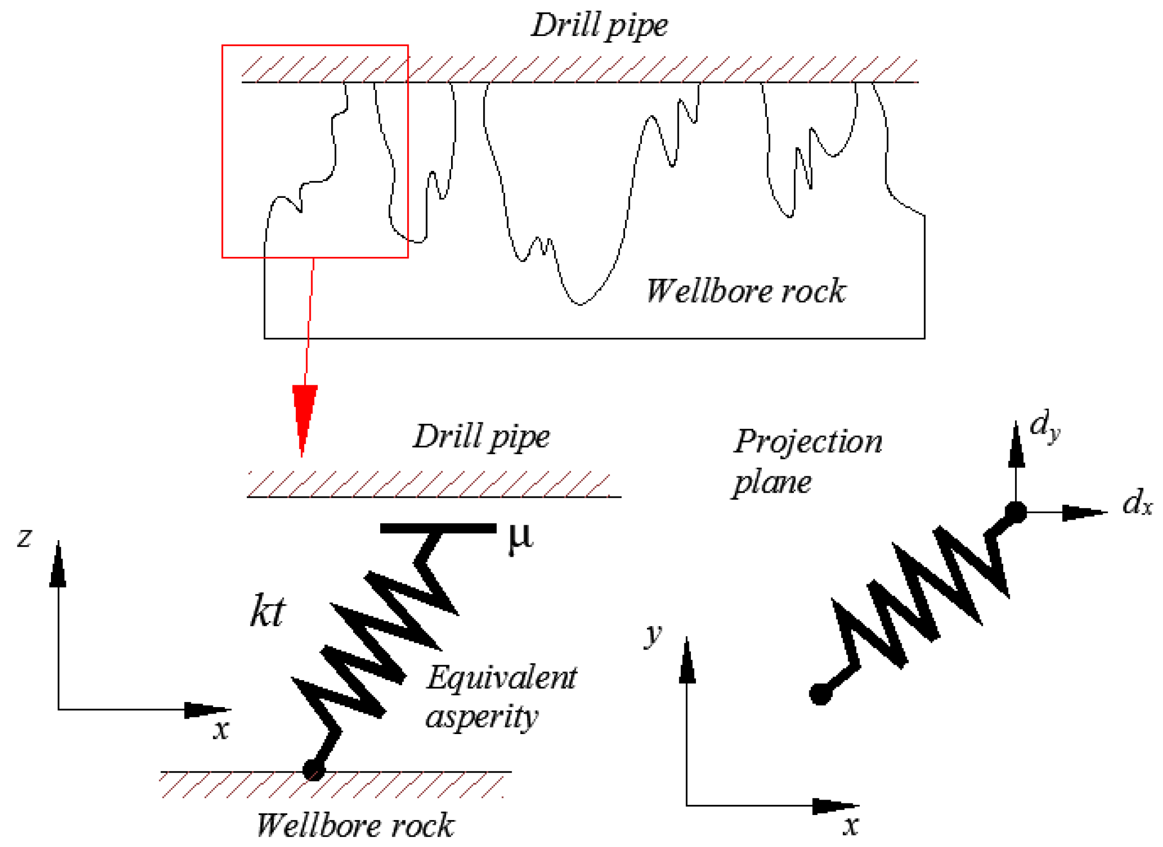
In the model used for further analysis, the deformation in the contact zone formed by the contact of general asperities sliding and the rotary drill string was modeled by a generalized elastic artificial element, which described the average behavior of the general asperities (Figure 10).
An elastic-damping deformation z of the contact artificial element at an optional instant t could be presented in the model as the distance of end-points O and N of the element. The artificial elements were on the micrometer-scale; the curvature of the wellbore surface could be ignored. The projected length of artificial element was determined by the coordinates of points O and M(t) [40], where M(t) is the projection of point N on the wellbore surface and can be expressed as follows:
| z ( t ) | = | O M ( t ) |
O ( t ) = [ 0 , 0 ]   and   M = [ x 0 , y o ]
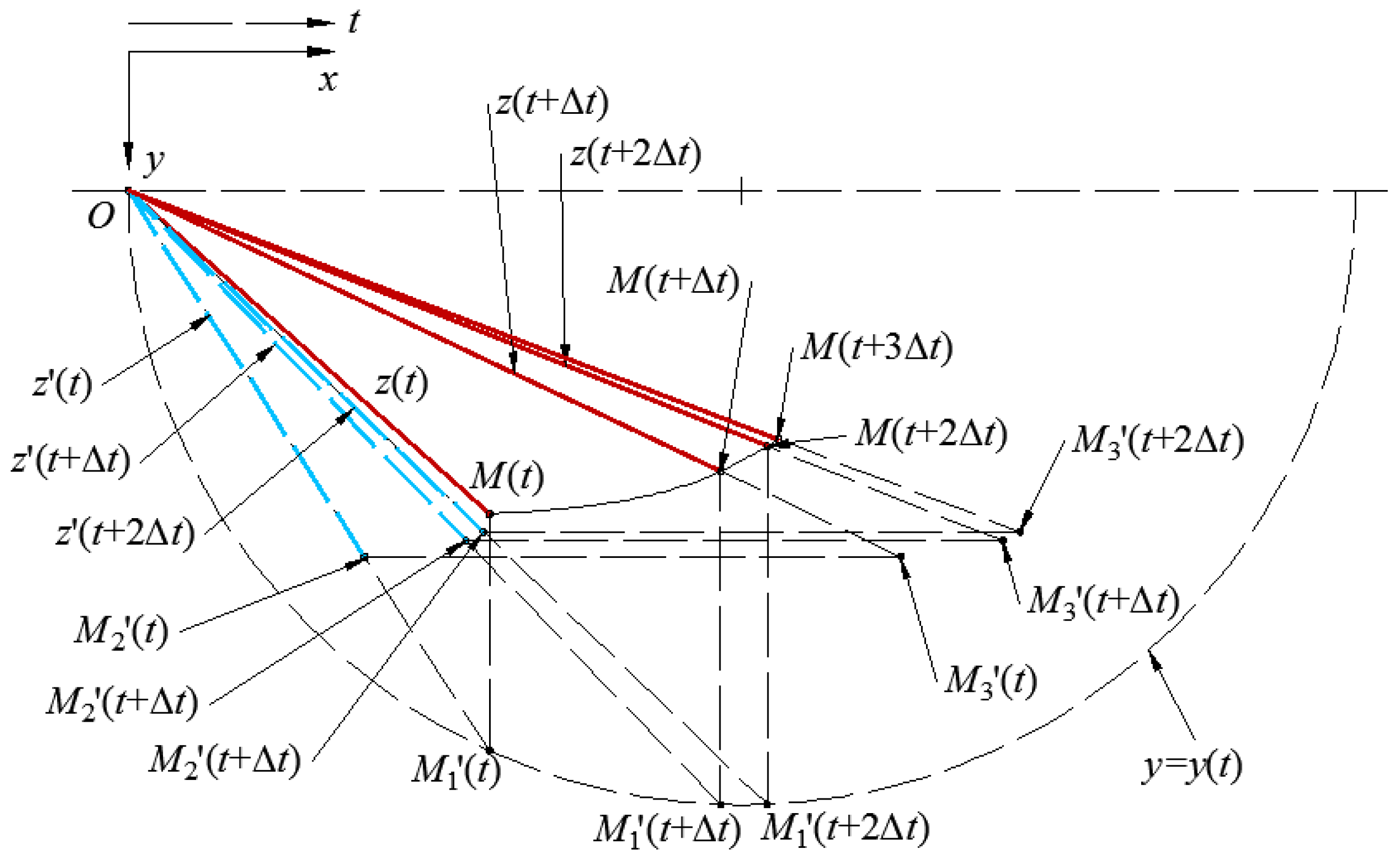
The position of M at any instant along the wellbore is the result of the superposition of motion caused by the drill string sliding and tangential motion. At consecutive instants, the point M changes its relative position and the elastic deformation z also undergoes a magnitude and directional change. The deformation of the elastic asperity is separated into two steps at any interval Δt [40,41].
In the first step, during the previous time step Δt, the instantaneous rotating velocity of the drill string leads to the motion of point M in the tangential direction. In the second step, the motion of point M is the result of the sliding motion of the drill string in the axial direction within the time step Δt.
At a consecutive time interval Δt, in the first step of the abovementioned motion, point M moves to the position M1’(t), which is determined by the following coordinates:
M 1 ( t ) = [ x 1 ,   y 1 ] = [ x 0 ,   y 0 + d y ]
The general asperity elastic deformation on the wellbore surface relies on the contact tangential stiffness kt. The deformation changes in its magnitude by an increment of Δz, which can be evaluated using Equation (7). In Figure 11, z’(t) is the actual magnitude of the elastic deformation of an asperity in the first step of motion and can be described by the following relationship:
z ( t ) = z ( t ) + Δ z = z ( t ) + [ v r 1 | v r 1 | z g ( v r ) ] Δ t
The velocity νr1 of the relative motion of the general asperity in the first step can be determined from the following expression:
v r 1 = | O M 1 ( t ) | | O M ( t ) | Δ t
Knowing the magnitude of elastic deflection z’(t), we are able to determine the end point M2’ position because the direction of z’(t) is along of vector O M 2 ( t ) . The coordinates are described as follows:
M 2 ( t ) = [ x 2 ,   y 2 ] = O M 1 ( t ) | z ( t ) | | O M 1 ( t ) | = [ x 1 ,   y 1 ] | z ( t ) | | O M 1 ( t ) |
The angle between the elastic deformation z ( t ) and the wellbore axial direction can be determined according to the imposed equation:
α = arccos ( O M 2 ( t ) · e 1 | O M 2 ( t ) | )
In the second step, during the following Δt time step, the drill string sliding leads to the motion of points M2’(t + Δt) in the longitudinal direction. After the expiry of Δt, the drill string sliding displacement is Δx. This displacement is related to the distance of M2’(t)M3’(t). The value of z ( t ) corresponds to the magnitude of the elastic deflection of the asperity after the time interval Δt. This can be described as follows:
z ( t + Δ t ) = z ( t ) + Δ z = z ( t ) + [ v r 2 | v r 2 | z ( t ) g ( v r ) ] Δ t
The velocity νr2 is approximately equal to the average velocity of point M2’(t + Δt) along the straight line OM3’(t). This value can be determined from the following equation:
v r 2 = | O M 3 ( t ) | | O M 2 ( t ) | Δ t
where O M 3 ( t ) = O M 2 ( t ) + d x e 1 . The magnitude of z ( t + Δ t ) is proportional to | O M 3 ( t ) | . O M 3 , that was (t + Δt)), can be determined from the following equation:
M 3 ( t ) = M ( t + Δ t ) = [ x 3 ,   y 3 ] = | O M 3 | | z ( t + Δ t ) | | O M 3 ( t ) |
The angle β between O M 3 ( t ) and the axial direction can be determined by the following expression:
β = arccos ( O M 3 ( t ) · e 1 | O M 3 ( t ) | )
We can obtain βv from the vector of the drill string with respect to the wellbore, the vector of the principle axis of asperity, and the vector of the asperity projection with respect to the wellbore.
v s l i p = ( d x e 1 + d y e 2 ) M ( t ) M ( t + Δ t )
β v = arccos ( v s l i p · e 3 | v s l i p | )
In the Dahl friction model [36,37], the deformation mechanism is determined from the following equation:
F f ( t ) = k t · z ( t )
Knowing the magnitude and direction of the elastic deformation z at any time interval Δt, the instantaneous value of the friction force f d and m d can be determined at this instant by utilizing the Dahl model.
f x = k t · z ( t + Δ t ) cos β
The torque caused by the asperity deformation is determined by the following expression:
m y = R 0 F y = R 0 [ k t · z ( t + Δ t ) ] sin β
The average magnitude of friction force F f x in the axial direction of the wellbore over a period of time relates to the magnitude of the friction force in this direction and is essential for initiating and sustaining the drill string motion.
This can be determined from the following relationship:
F x = 1 n | f x ( t n ) |
The average magnitude of the friction torque M f y during a period of motion of the drill string can be described as follows:
M y = 1 n | m y ( t n ) |
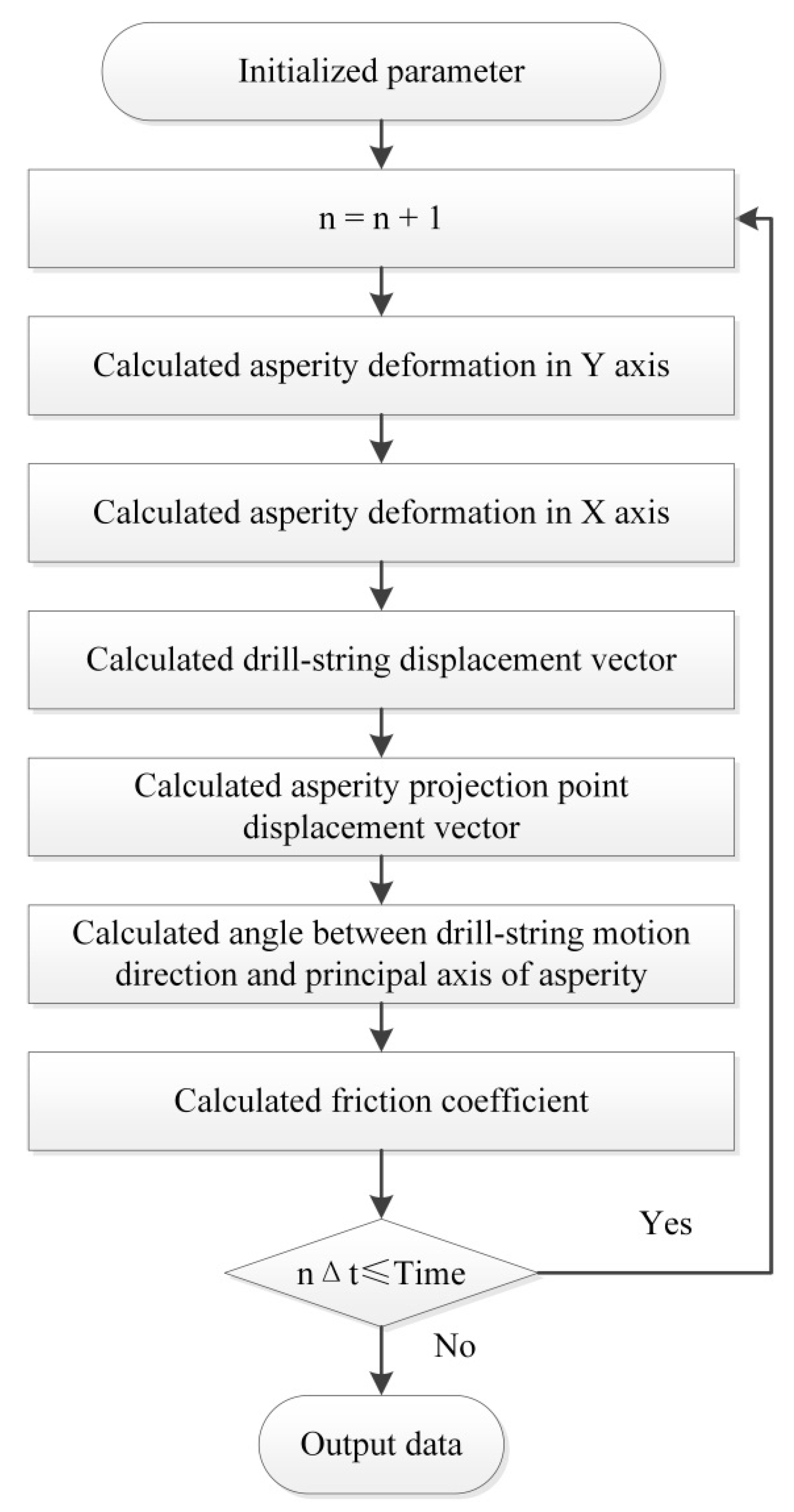
The solving process of the multiscale friction model was presented in the Figure 12.

4. Model Verification

This section adopted the published experimental results [41,42] to validate the established model. Sandstone was most common rock of the wellbore. The frequency of downhole vibration technologies was extremely low compared to the experimental parameter in previously published papers [41,42]. The experimental results reflected the friction coefficient created between sandstone and metal under a longitude vibration of 100 Hz. The aforementioned model can be simulated using MATLAB.
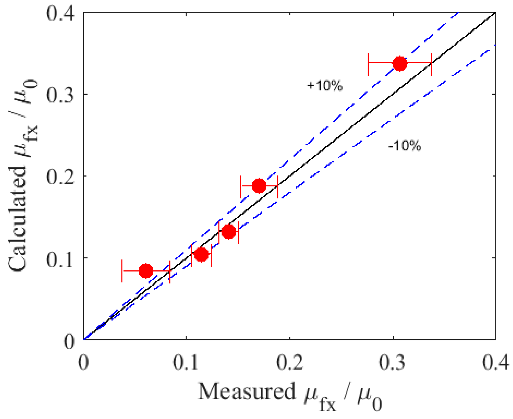
Particle Swarm Optimization (PSO) was adopted to identify the parameters of the established model. The adaptive function of PSO revealed a negative difference between the calculated and the measured values. The results of the parameters identification are listed as follows: kt was 42.7 (N/mm), a was 10.45 μm, b was 15.65 μm, and h was 5.09 μm. An analysis of the results is presented in Figure 13 and Figure 14. The errors between the model prediction and experimental measurements were less than 10%. The established model could effectively describe the friction between metal and rock, as presented in the Figure 13 and Figure 14.

5. Mechanism of Friction Reduction Tools

The friction reduction mechanism of DAS and Slider Drilling Technology was analyzed in this section using the established friction model.

5.1. Computational Parameters

The simulation work adopted the parameters reported in a previously published article [10,13]. These parameters are listed in Table 1. The parameters of the multiscale friction model adopted result are listed in Section 4.

5.2. Friction Characteristic of the DAS

5.2.1. Longitudinal Oscillation

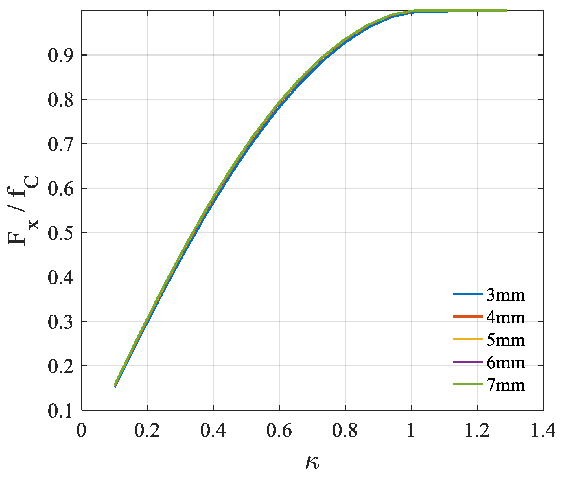
Most DASs adopt longitudinal vibration as their motion pattern [43,44,45]. Using the aforementioned model, the friction characteristic of the DAS was investigated. The motion of the DAS was an axial sine oscillation with a constant slipping velocity. The amplitude of the longitudinal vibration was 2 mm to 7 mm with a 1-mm step. The frequency of the oscillation was 15 Hz. The slipping velocity (also called the rate of penetration (ROP)) was 7 m/h. The simulation results are presented in Figure 15.
The numerical results for the DAS case are shown in Figure 13. In the figure, one can see that the dependence of the reduced coefficient of friction on the reduced oscillation amplitude exceeds the critical value of 1. There was little effect on the ratio of the average axial friction to the Coulomb friction caused by the varied amplitude of the longitudinal oscillation.
The effect of the frequency of axial vibration was also studied. The frequency of axial oscillation was set at 5 Hz, 10 Hz, 15 Hz, and 20 Hz. The ROP was 10 m/h. The simulation result is presented in Figure 16. According to the result, there was no effect on the axial friction caused by the varied frequency of the longitudinal oscillation.

5.2.2. Radial Oscillation

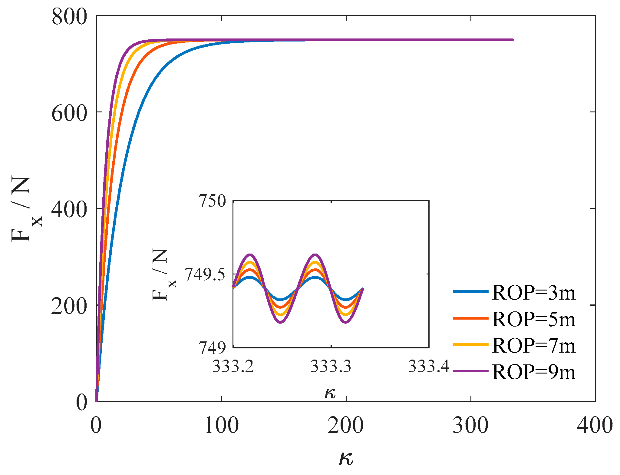
Some of the DASs adopted radial vibration as their working mode [19]. This section analyzed the friction characteristic of the DAS with radial vibration. The ROPs were 3 m/h, 5 m/h, 7 m/h, and 9 m/h. According to the structure of the radial vibration DAS, the motion pattern of the radial DAS should be sine or cosine.
The frequency of vibration was equal to 15 Hz in the simulation case. The amplitude of the radial vibration force was equal to 30% of the gravity of the drilling pipe. The simulation results are shown in Figure 17. The values of the axial friction force with different ROPs finally became close to each other in the stable stage. In the stable stage, the axial friction force exhibited a slight fluctuation. However, the mid-values of the axial friction force were maintained at the same value, even with different ROPs.
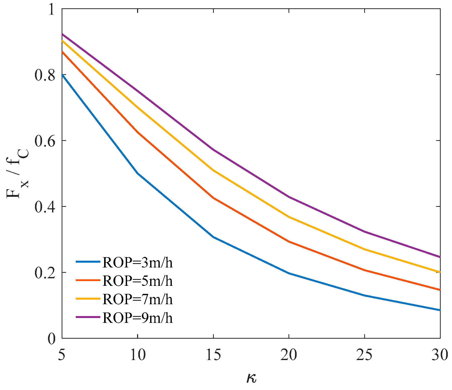
The amplitude of the radial vibration was analyzed with respect to the axial friction. The ROPs were 3 m/h, 5 m/h, 7 m/h, and 9 m/h. The ratios of radial vibration ranged from 0.1 to 0.6. According to the simulation results, as presented in Figure 18, the axial friction decreased with the increasing ratios. There were small distinctions between the axial friction forces with different ROPs. It was shown that the frequency of radial vibration did not impact the axial friction. This indicated that the increased amplitude of the radial vibration could effectively reduce the axial friction force. However, the amplitude of the axial friction decreased to less than 20%.

5.2.3. Torsional Oscillation

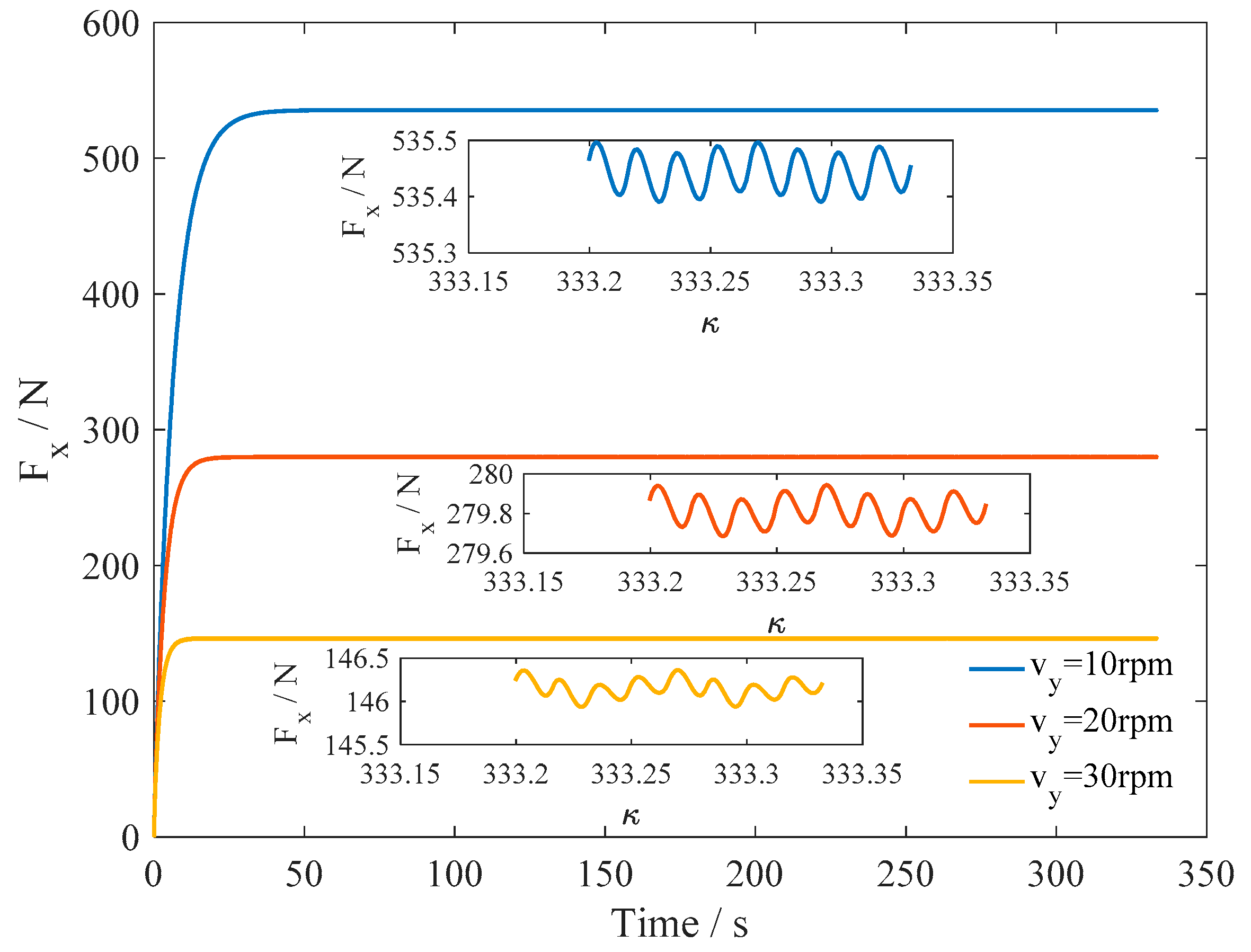
Torsional oscillation was also an important vibration form of friction reduction. The axial friction was simulated while the drilling pipe was subjected to torsional vibration. The ROP was 10 m/h. The motion pattern of the torsional DAS was assumed to be sine. The amplitudes of torsional vibration were 10 rpm, 20 rpm, and 30 rpm. These were common parameters employed in the field [21].
As shown in Figure 19, the results indicated that the axial friction force reached a steady-state oscillation after the early oscillation. The lower amplitude of the torsional vibration led to a larger axial friction force. The larger amplitude of the torsional vibration led to a lower axial friction force. The simulation demonstrated that torsional oscillation could effectively reduce the axial friction of the drill string and that the drag reduction effect was correlated to the amplitude of the torsional vibration.
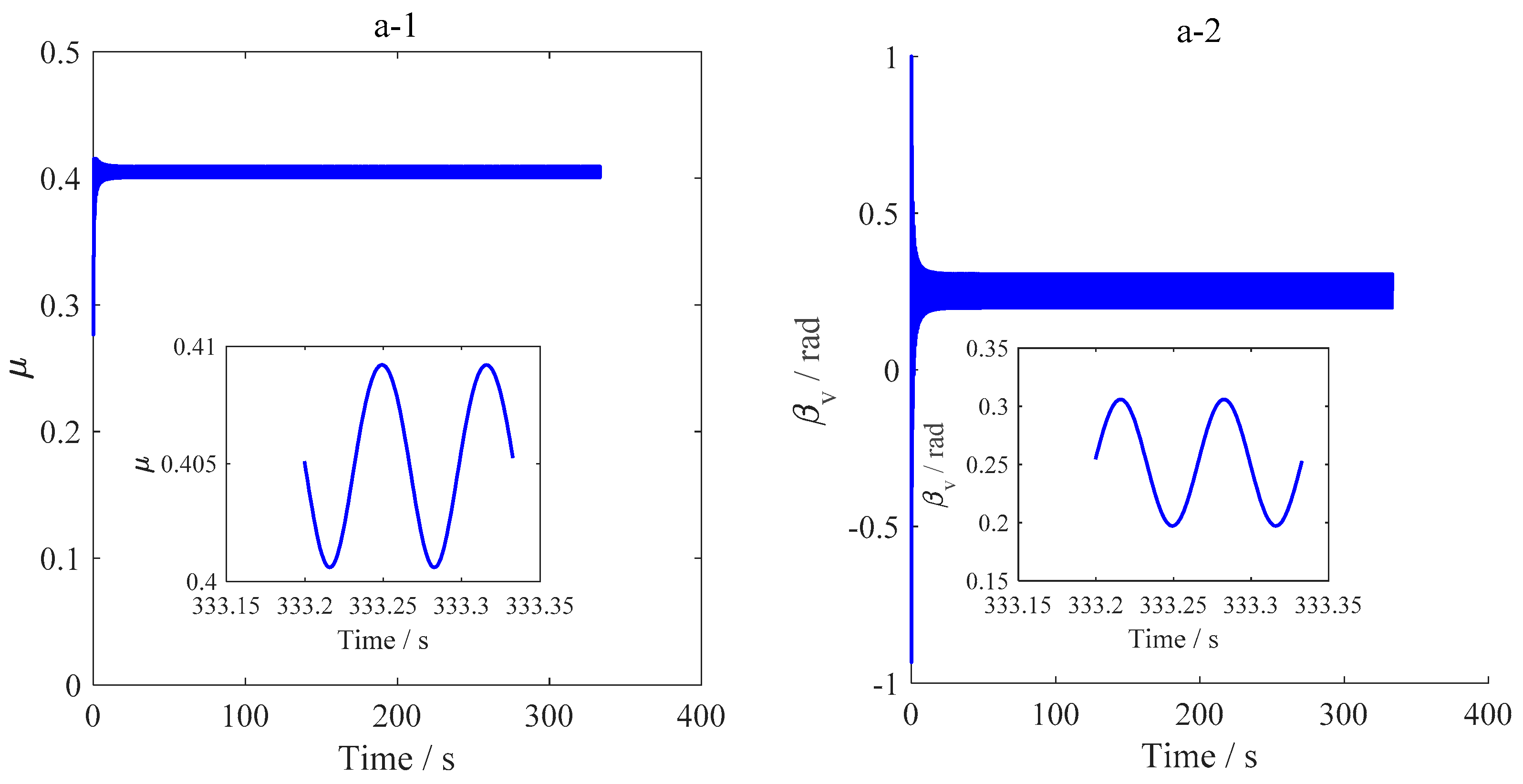
According to the multiscale friction model, Figure 20 presents the friction coefficient and angle between the drill string motion direction and the principal axis of asperity. There were smaller variation ranges of friction with a low amplitude of torsional vibration, as shown in Figure 20. This was due to the greater variation ranges of the angle between the drill string motion direction and the principal axis of asperity. The pattern of varied angles was similar to that of the sine function.
As discussed, this was due to the fact that the asperity deformation and the drill string motion were on the millimeter-scale. The relative movement led to the variation of the angle between the drill string motion direction and the principal axis of asperity. In turn, the varied angles led to the variation of the friction coefficient.
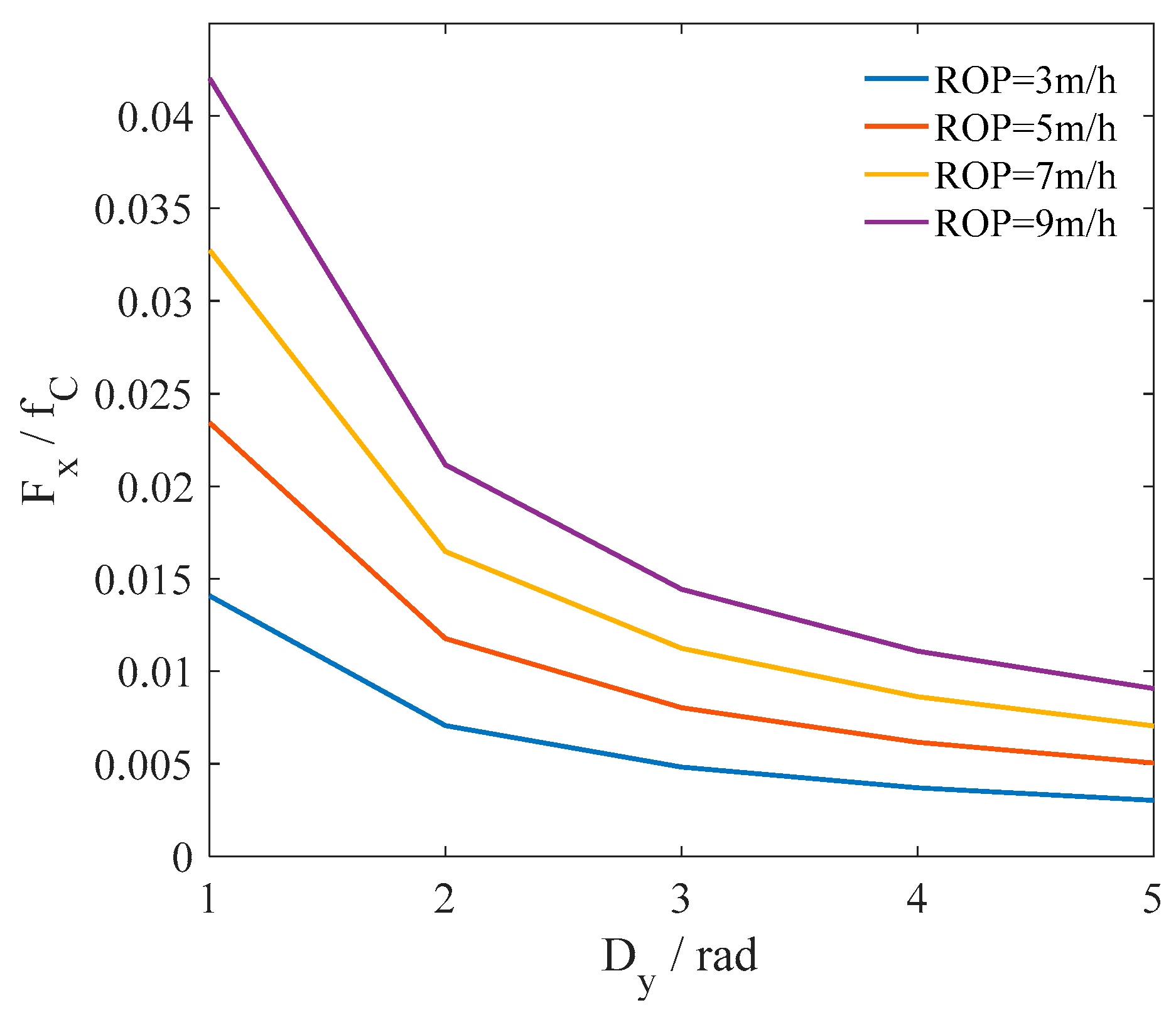
The ratios between the average axial friction force and the Coulomb friction were also computed when the ROPs were 3 m/h, 5 m/h, 7 m/h, and 9 m/h. The ratios decreased as the amplitude of the torsional oscillation increased, as presented in Figure 21. The slope of the decrease of the ratio was fast at first and finally slow. The axial friction force was larger when the ROP was greater. The slope derivatives of the ratio curves were different. The changes of slope with a low ROP were sharper than the changes of slope with greater ROPs. This was different from the results reported in Reference [10].

5.3. Friction Characteristic of Slider Drilling Technology

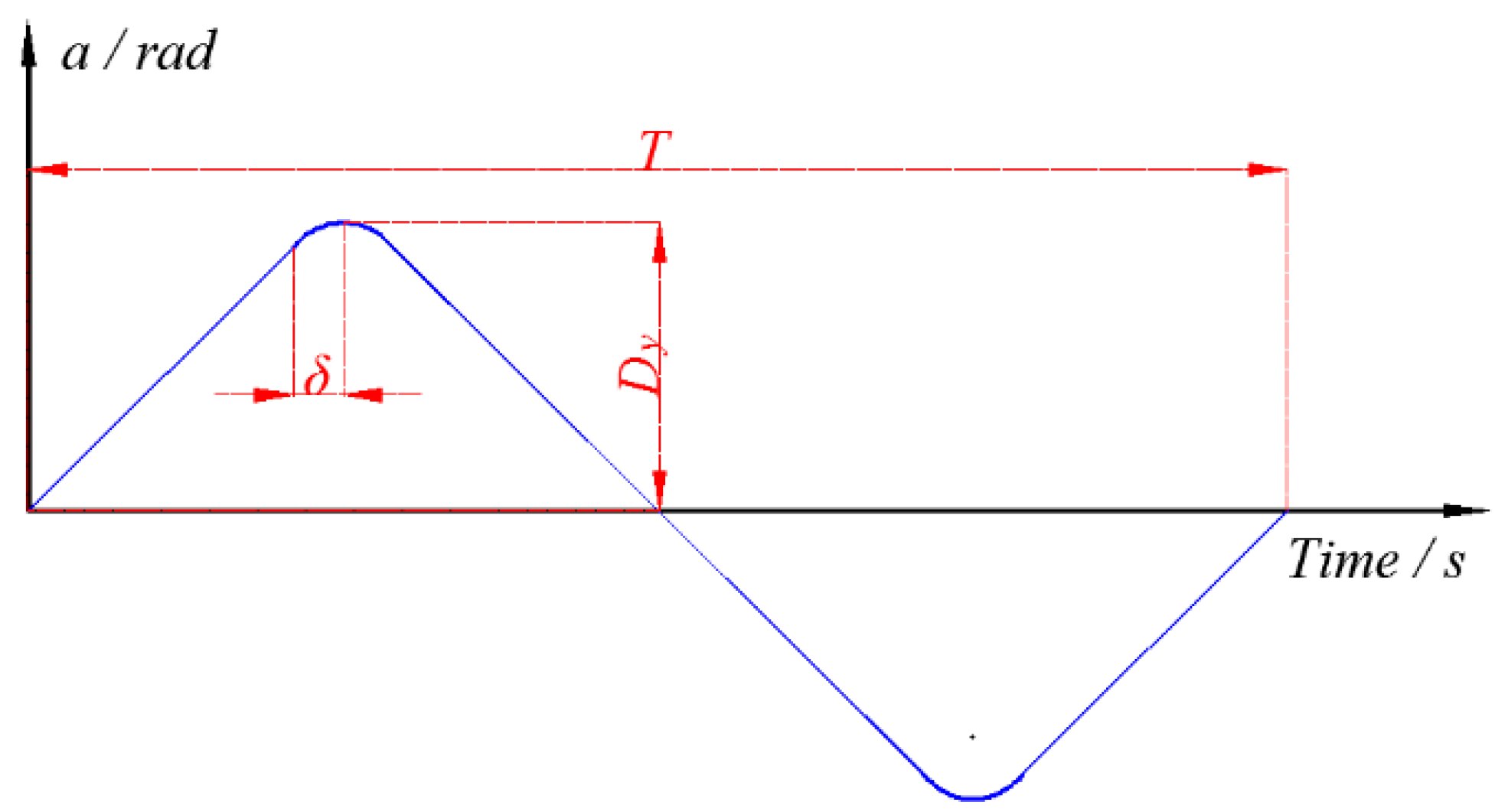
The surface motion of Slider Drilling Technology was very complex. The actual trajectory of the motion was controlled by an automatic program. The program decided output commands based on signals from surface torque and stand pipe pressure sensors. To analyze the friction reduction mechanism, the paper adopted a surface motion trajectory in the ideal condition [46], as shown in Figure 22.
As presented in Figure 20, the ideal trajectory was similar to a triangle wave. However, the peak points of the triangle were rounded by a circular arc. The width of the circular arc was double δ. The amplitude of the motion was Dy. The period was T. The slope of the straight lines was −4 Dy/T or 4 Dy/T.
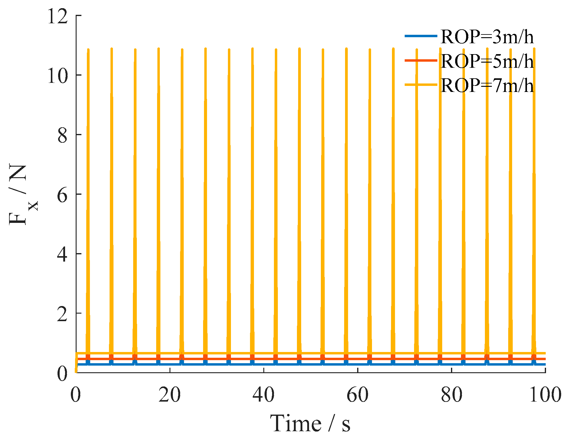
The simulations were conducted using the ideal surface trajectory. The period T was equal to 10 s. Dy was equal to 10 rad. δ was equal to 0.2 s. The ROPs were equal to 1 m/h, 3 m/h, 5 m/h, and 7 m/h. The simulation results are presented in Figure 23.
The axial friction forces were stable and low when the rotation speed was constant. When the rotation direction shifted, these forces rapidly increased and decreased. A lower ROP led to a smaller axial friction force, in both the stable region and the changed region.
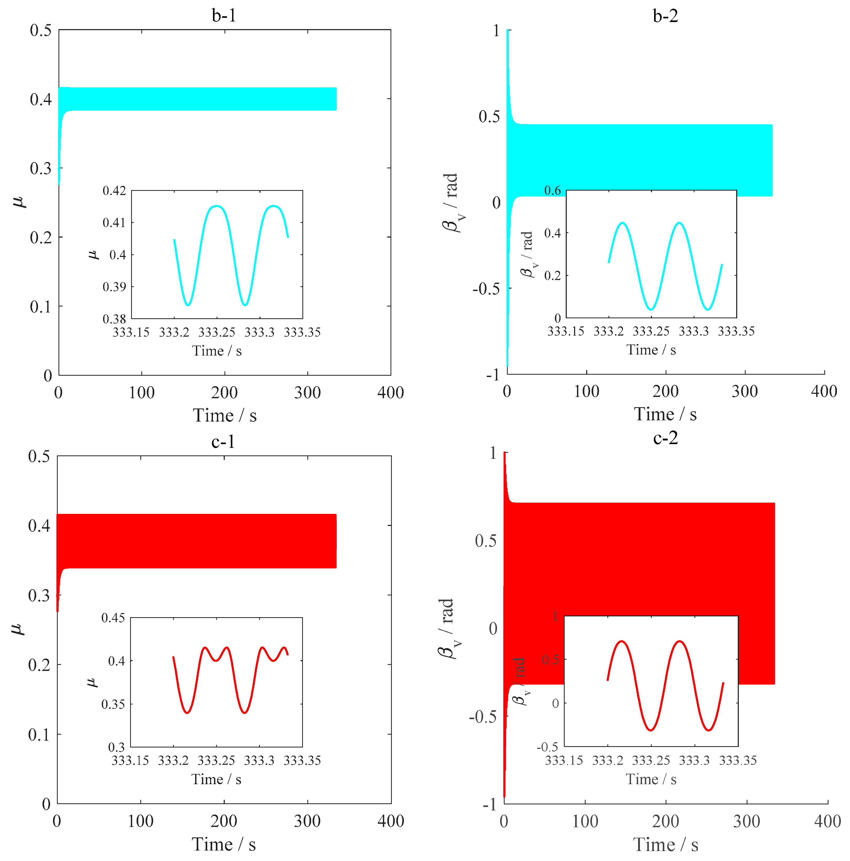
According to the simulation results, Figure 24 presents the friction coefficient and angle between the drill string motion direction and the principal axis of asperity with different ROPs. The maximum angle of the rocking motion was 30 rad. The difference between these angles was not obvious. The direction of the asperity deformation was stable when the tangential velocity was constant. The difference between these angles was not obvious, which was attributed to the asperity deformation. This implied that the asperity deformation reduced the change of the angle between the drill string motion direction and the principal axis of asperity. However, the friction coefficients were slightly different from the distinct ROPs when the rotation direction was shifted. The greater tangential velocity resulted in larger axial friction coefficients.
The average axial friction forces were also obtained by simulation. The results are presented in Figure 25. The ratio between the average axial friction force and the Coulomb friction decreased with the increase of the amplitude of the rotation. A greater ROP led to a greater axial friction force under the condition of the same rotation amplitude. The friction reduction effect was more obvious than that of longitudinal vibration and torsional vibration in the range of the field parameters.

6. Conclusions

This article introduced vibration technologies, including three kinds of Drilling Agitator Systems and Slider Drilling Technologies, to overcome the weight transfer challenge in Horizontal Wells. The abovementioned techniques are the most popular friction reduction technologies employed in the field. According to the structure of the tool, the motions of vibration technologies were summarized. The DAS adopted longitudinal vibration, radial vibration, and torsional vibration to reduce the axial friction force. The Slider Drilling Technologies adopted rotating movement to reduce the axial friction force.
This paper also introduced a multiscale friction model to provide insight on the mechanism of friction reduction of vibration technologies. The model was verified by experimental data. The parameters of the model were identified using the PSO method. The multiscale friction model considered the asperity deformation on the millimeter-scale and the contact of asperity and the drill string on the micrometer-scale. Meanwhile, the model also considered the effect of asperity deformation on the contact angle.
The motion of the aforementioned vibration technologies was analyzed using the established model. The simulation parameters were in the range of actual practice in the field. The simulation results indicated that the four kinds of technology can reduce the axial friction of the drilling string. Longitudinal vibration can reduce axial friction when the slipping velocity is less than the amplitude of the axial vibration. However, radial vibration is not compact on axial friction with different ROPs. Torsional vibration and rocking motion not only change the axial component of friction force, but also change the friction coefficient between the wellbore and the drill string. According to the simulation results, the drag reduction of rocking motion was better than longitudinal, torsional, and lateral vibration.

Author Contributions

Methodology, X.-M.W.; Software, X.-M.W. and X.-M.Y.; Validation, X.-M.W.; Formal Analysis, X.-M.W. and X.-M.Y.; Investigation, X.-M.W.; Resources, X.-M.W.; Data Curation, X.-M.W.; Writing-Original Draft Preparation, X.-M.W.; Writing-Review & Editing, X.-M.W. and X.-M.Y.; Visualization, X.-M.W.; Supervision, X.-M.W.; Project Administration, X.-M.W.; Funding Acquisition, X.-M.W., X.-M.Y.

Acknowledgments

This research was sponsored by the Sichuan Province Science and Technology Program (Grant No. 2015SZ0003).

Conflicts of Interest

The authors declare no conflict of interest.

Nomenclature

θattack angle of wedge-shaped asperity
fCshear factor
μcuttingfriction coefficient in the cutting regime
μploughingfriction coefficient in the ploughing regime
μwearfriction coefficient in the wedge formation regime
A1, A2coefficient
aminor axis of asperity
bmajor axis of asperity
hheight of asperity
dxdrill string displacement in the X direction
dydrill string displacement in the Y direction
e1unit vector of the axial direction
e2unit vector of the tangential direction
e3unit vector of the principle axis of asperity
zprojection of the length of asperity
zvirtual projection of the length of asperity
ktstiffness of asperity
vrrelative velocity
FNnormal force
iindex of the Dahl model
Mprojection point
Mvirtual projection point
Ofixed point of asperity
α, βangle between the direction of asperity projection and the axial of the wellbore
βvangle between the drill string motion direction and the principal axis of asperity
FcCoulomb friction
Fffriction force of the multiscale friction model
Fxaverage axial friction force
fxaxial friction force
Myaverage axial friction torque
mytangential friction torque
R0outer diameter of the drill string
κratio between the amplitude of the vibration velocity and the slip velocity
χratio between the amplitude of the vibration force and the gravity of the drill string

References

  1. Rui, Z.; Guo, T.; Feng, Q.; Qu, Z.; Qi, N.; Gong, F. Influence of gravel on the propagation pattern of hydraulic fracture in the glutenite reservoir. J. Pet. Sci. Eng. 2018, 165, 627–639. [Google Scholar] [CrossRef]
  2. Rui, Z.; Wang, X.; Zhang, Z.; Lu, J.; Chen, G.; Zhou, X.; Patil, S. A realistic and integrated model for evaluating oil sands development with Steam Assisted Gravity Drainage technology in Canada. Appl. Energy 2018, 213, 76–91. [Google Scholar] [CrossRef]
  3. Thomas, R.L.; Mckeever, S.O.; Hartwig, D.D.; Egedahl, D.B.; Patton, J.; Holtzman, K.; Smith, L. Overcoming Weight Transfer Challenges in Complex, Shallow, Extended Reach Wells on Alaska’s North Slope. In Proceedings of the Offshore Technology Conference, Houston, TX, USA, 5–8 May 2008. (OTC-19550-MS). [Google Scholar]
  4. Stuart, D.; Hamer, C.D.; Henderson, C.; Gaynor, T.; Chen, D.C.-K. New Drilling Technology Reduces Torque and Drag by Drilling a Smooth and Straight Wellbore. In Proceedings of the SPE/IADC Drilling Conference, Amsterdam, The Netherlands, 19–21 February 2003. (SPE-79919-MS). [Google Scholar]
  5. Mccormick, J.E.; Chiu, T.F. The Practice and Evolution of Torque and Drag Reduction: Theory and Field Results. In Proceedings of the SPE Annual Technical Conference and Exhibition, Denver, CO, USA, 30 October–2 November 2012. (SPE-147100-MS). [Google Scholar]
  6. Maehs, J.; Renne, S.; Logan, B.; Diaz, N. Proven Methods and Techniques to Reduce Torque and Drag in the Pre- Planning and Drilling Execution of Oil and Gas Wells. In Proceedings of the IADC/SPE Drilling Conference and Exhibition, New Orleans, LA, USA, 2–4 February 2010. (IDAC/SPE128329). [Google Scholar]
  7. Schuh, F.J.; Coragliotti, A.; Dicicco, C.D.; Nagatani, R.A.; Rea, A.; Carlton, T.; Johnson, P.; Noble, R. Characterization of Encapsulated Oil as an Additive to Water-Based Drilling Fluids: Operational Improvements in Lubricity, Drag, and ROP. In Proceedings of the SPE Western North American and Rocky Mountain Joint Meeting, Denver, CO, USA, 17–18 April 2014. (SPE-169547-MS). [Google Scholar]
  8. Livescu, S.; Craig, S.H.; Watkins, T. Challenging the Industry’s Understanding of the Mechanical Friction Reduction for Coiled Tubing Operations. In Proceedings of the SPE Annual Technical Conference and Exhibition, Amsterdam, The Netherlands, 27–29 October 2014. (SPE-170635-MS). [Google Scholar]
  9. Patel, A.; Zhang, H.J.; Ke, M.; Panamarathupalayam, B. Lubricants and Drag Reducers for Oilfield Applications—Chemistry Performance and Environmental Impact. In Proceedings of the SPE International Symposium on Oilfield Chemistry, The Woodlands, TX, USA, 8–10 April 2013. (SPE-164049-MS). [Google Scholar]
  10. Wang, X.; Chen, P.; Rui, Z.; Jin, F. Modeling Friction Performance of Drill String Torsional Oscillation Using Dynamic Friction Model. Shock Vib. 2017, 2017, 4051541. [Google Scholar] [CrossRef]
  11. Wang, X.; Chen, P.; Ma, T.; Liu, Y. Modeling and experimental investigations on the drag reduction performance of an axial oscillation tool. J. Nat. Gas Sci. Eng. 2017, 39, 118–132. [Google Scholar] [CrossRef]
  12. Herrington, D.; Mercer, S. Fully Mechanical 3D Rotary Steering Technology Provides Economical Alternative to Conventional Rotary Steerable Tools. In Proceedings of the SPE Annual Technical Conference and Exhibition, New Orleans, LA, USA, 30 September–2 October 2013. (SPE-166517-MS). [Google Scholar]
  13. Gillan, C.; Kostiuk, G.; Schlembach, C.; Pinto, J.; LeBlanc, M. Applying Precision Drill Pipe Rotation and Oscillation to Slide Drilling Problems. In Proceedings of the SPE/IADC Drilling Conference and Exhibition, Amsterdam, The Netherlands, 17–19 March 2009. (SPE/IADC-118656). [Google Scholar]
  14. Heisig, G.; Macpherson, J.D.; Mounzer, F.; Linke, C.; Jenkins, M.A. Bending Tool Face Measurement While Drilling Delivers New Directional Information, Improved Directional Control. In Proceedings of the IADC/SPE Drilling Conference and Exhibition, New Orleans, LA, USA, 2–4 February 2010. (SPE-128789-MS). [Google Scholar]
  15. Barton, S.P.; Baez, F.; Alali, A. Drilling Performance Improvements in Gas Shale Plays using a Novel Drilling Agitator Device. In Proceedings of the North American Unconventional Gas Conference and Exhibition, The Woodlands, TX, USA, 14–16 June 2011. (SPE-144416-MS). [Google Scholar]
  16. Clausen, J.R.; Schen, A.E.; Forster, I.; Prill, J.; Gee, R. Drilling With Induced Vibrations Improves ROP and Mitigates Stick/Slip in Vertical and Directional Wells. In Proceedings of the IADC/SPE Drilling Conference and Exhibition, Fort Worth, TX, USA, 4–6 March 2014. (SPE-168034-MS). [Google Scholar]
  17. Martinez, J.; Carson, C.R.; Canuel, L.A.P.; Burnett, T.G.; Gee, R. New Technology Enables Rigs With Limited Pump Pressure Capacity to Utilize the Latest Friction Reduction Technology. In Proceedings of the SPE Eastern Regional Meeting, Pittsburgh, PA, USA, 20–22 August 2013. (SPE-165700-MS). [Google Scholar]
  18. Lv, J.; Liu, X.; Qian, L.; Xia, C.; Liu, F.; Hua, Y.; Li, M. Study on the Influence Factors of Performance of the 3D Hydraulic Oscillator. China Pet. Mach. 2016, 44, 27–30. [Google Scholar]
  19. Hess, D.P.; Soom, A. Normal Vibrations and Friction under Harmonic Loads: Part I—Hertzian Contacts. J. Tribol. 1991, 113, 87–92. [Google Scholar] [CrossRef]
  20. Zhang, H.; Guan, Z.; Liu, Y.; Dou, Y. Development of drilling string excitation drag reduction tool based on rotary excitation. China Pet. Mach. 2015, 43, 9–12. [Google Scholar]
  21. Maidla, E.; Haci, M.; Jones, S.; Cluchey, M.; Alexander, M.; Warren, T. Field Proof of the New Sliding Technology for Directional Drilling. In Proceedings of the SPE/IADC Drilling Conference, Amsterdam, The Netherlands, 23–25 February 2005. (SPE-92558-MS). [Google Scholar]
  22. Maidla, E.E.; Wojtanowicz, A.K. Laboratory Study of Borehole Friction Factor with a Dynamic-Filtration Apparatus. SPE Drill. Eng. 1990, 5, 247–255. [Google Scholar] [CrossRef]
  23. Gillan, C.; Boone, S.; Leblanc, M.; Picard, R.P.; Fox, R.T. Applying Computer Based Precision Drill Pipe Rotation and Oscillation to Automate Slide Drilling Steering Control. In Proceedings of the Canadian Unconventional Resources Conference, Calgary, AB, Canada, 15–17 November 2011. (SPE-148192-MS). [Google Scholar]
  24. Maidla, E.E.; Haci, M.; Wright, D. Case History Summary: Horizontal Drilling Performance Improvement Due to Torque Rocking on 800 Horizontal Land Wells Drilled for Unconventional Gas Resources. In Proceedings of the SPE Annual Technical Conference and Exhibition, New Orleans, LA, USA, 4–7 October 2009. (SPE-123161-MS). [Google Scholar]
  25. Maidla, E.; Haci, M. Understanding Torque: The Key to Slide-Drilling Directional Wells. In Proceedings of the IADC/SPE Drilling Conference, Dallas, TX, USA, 2–4 March 2004. (SPE-87162-MS). [Google Scholar]
  26. Kragjcek, R.H.T.; Al-Dossary, A.; Kotb, W.; Al Gamal, A. Automated Technology Improved the Efficiency of Directional Drilling in Extended Reach Wells in Saudi Arabia. In Proceedings of the SPE/DGS Saudi Arabia Section Technical Symposium and Exhibition, Al-Khobar, Saudi Arabia, 15–18 May 2011. (SPE-149108-MS). [Google Scholar]
  27. Urbakh, M.; Klafter, J.; Gourdon, D.; Israelachvili, J. The nonlinear nature of friction. Nature 2004, 430, 525–528. [Google Scholar] [CrossRef] [PubMed]
  28. Dougherty, P.S.M.; Pudjoprawoto, R.; Iii, C.F.H. Bit cutter-on-rock tribometry: Analyzing friction and rate-of-penetration for deep well drilling substrates. Tribol. Int. 2014, 77, 178–185. [Google Scholar] [CrossRef]
  29. Greenwood, J.A.; Williamson, J.B.P. Contact of nominally flat surfaces. Proc. R. Soc. Lond. A Math. Phys. Eng. Sci. 1966, 295, 300–319. [Google Scholar] [CrossRef]
  30. Majumdar, A.; Bhushan, B. Fractal model of elastic-plastic contact between rough surfaces. J. Tribol. 1991, 113, 1–11. [Google Scholar] [CrossRef]
  31. Challen, J.M.; Oxley, P.L.B. An explanation of the different regimes of friction and wear using asperity deformation models. Wear 1979, 53, 229–243. [Google Scholar] [CrossRef]
  32. Challen, J.M.; Oxley, P.L.B. Slip-line fields for explaining the mechanics of polishing and related processes. Int. J. Mech. Sci. 1984, 26, 403–418. [Google Scholar] [CrossRef]
  33. Hol, J. Multi-Scale Friction Modeling for Sheet Metal Forming; University of Twente: Enschede, The Netherlands, 2013. [Google Scholar]
  34. Westeneng, J.D. Modelling of Contact and Friction in Deep Drawing Processes; University of Twente: Enschede, The Netherlands, 2001. [Google Scholar]
  35. Ma, X.; Rooij, M.D.; Schipper, D. A load dependent friction model for fully plastic contact conditions. Wear 2010, 269, 790–796. [Google Scholar] [CrossRef]
  36. Dahl, P.R. A Solid Friction Model; Aerospace Corp: El Segundo, CA, USA, 1968. [Google Scholar]
  37. Dahl, P.R. Measurement of Solid Friction Parameters of Ball Bearings; Aerospace Corp El Segundo CA Engineering Science Operations: El Segundo, CA, USA, 1977. [Google Scholar]
  38. Piatkowski, T. Dahl and LuGre dynamic friction models—The analysis of selected properties. Mech. Mach. Theory 2004, 73, 91–100. [Google Scholar] [CrossRef]
  39. Olsson, H.; Åström, K.J.; Wit, C.C.D.; Lischinsky, P. Friction Models and Friction Compensation. Eur. J. Control 1998, 4, 5517–5522. [Google Scholar] [CrossRef]
  40. Tsai, C.C.; Tseng, C.H. The effect of friction reduction in the presence of in plane vibrations. Arch. Appl. Mech. 2006, 75, 164–176. [Google Scholar] [CrossRef]
  41. Gutowski, P.; Leus, M. The effect of longitudinal tangential vibrations on friction and driving forces in sliding motion. Tribol. Int. 2012, 55, 108–118. [Google Scholar] [CrossRef]
  42. Wang, P.; Ni, H.; Wang, R.; Liu, W.; Lu, S. Research on the Mechanism of In-Plane Vibration on Friction Reduction. Materials 2017, 10, 1015. [Google Scholar] [CrossRef] [PubMed]
  43. Wang, P.; Ni, H.; Wang, R.; Li, Z.; Wang, Y. Experimental investigation of the effect of in-plane vibrations on friction for different materials. Tribol. Int. 2016, 99, 237–247. [Google Scholar] [CrossRef]
  44. Wang, P.; Ni, H.; Li, Z.; Wang, R. A Modified Model for Friction Reduction by Vibrating Drill-String Longitudinally. Appl. Mech. Mater. 2014, 535, 597–601. [Google Scholar] [CrossRef]
  45. Wang, P.; Ni, H.; Wang, X.; Wang, R.; Lu, S. Research on the characteristics of earthworm-like vibration drilling. J. Pet. Sci. Eng. 2017, 160, 60–71. [Google Scholar] [CrossRef]
  46. Wang, X.; Ni, H.; Wang, R.; Liu, T.; Xu, J. Modeling and analyzing the movement of drill string while being rocked on the ground. J. Nat. Gas Sci. Eng. 2017, 39, 28–43. [Google Scholar] [CrossRef]
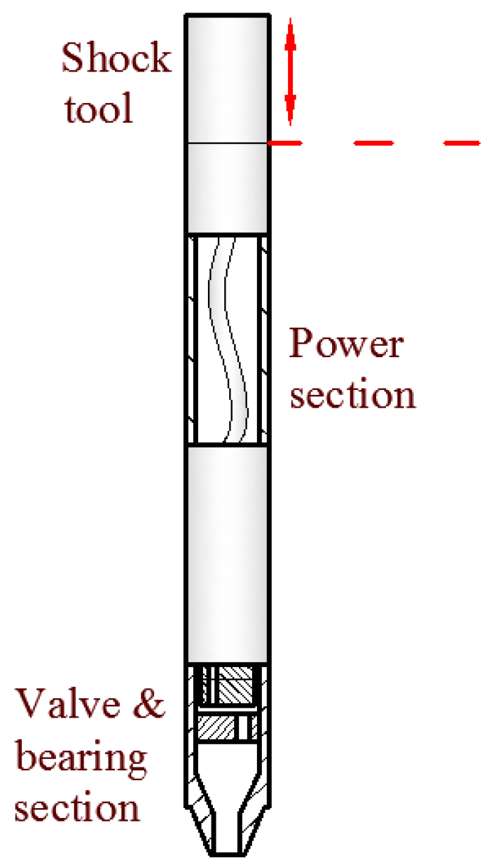
Figure 1. NOV Hydraulic Oscillation System.
Lubricants 06 00053 g001
Figure 2. Torsional vibration of the three-dimensional (3D) Hydraulic Oscillation System.
Lubricants 06 00053 g002
Figure 3. Radial hydraulic oscillator.
Lubricants 06 00053 g003
Figure 4. Control system architecture of Slider Drilling Technology.
Lubricants 06 00053 g004
Figure 5. Slider Drilling Technology.
Lubricants 06 00053 g005
Figure 6. Modeling of the contact’s elastic deformation [10].
Lubricants 06 00053 g006
Figure 7. Contact area between the well rock and drill string [10].
Lubricants 06 00053 g007
Figure 8. Wear-mode diagram.
Lubricants 06 00053 g008
Figure 9. Schematic view of the geometrical characteristics of contact asperities.
Lubricants 06 00053 g009
Figure 10. Schematic view of the asperity deformation projection.
Lubricants 06 00053 g010
Figure 11. Changes in general asperities deformation at consecutive phases of sliding and vibration of the drill string [10]. The blue dotted line is virtual projected element in the calculation process, the dark red solid line is real projected element at end of time step.
Lubricants 06 00053 g011
Figure 12. Flow diagram of the solving process of the multiscale friction model.
Lubricants 06 00053 g012
Figure 13. Model verification using experimental data.
Lubricants 06 00053 g013
Figure 14. Error analysis between the calculation and experimental data.
Lubricants 06 00053 g014
Figure 15. Axial friction force of the longitudinal oscillation with different rates of penetration (ROPs).
Lubricants 06 00053 g015
Figure 16. Axial friction force with longitudinal oscillation with different amplitudes of vibration.
Lubricants 06 00053 g016
Figure 17. Axial friction force with radical oscillation with different ROPs.
Lubricants 06 00053 g017
Figure 18. Axial friction force with radical oscillation with different ratios.
Lubricants 06 00053 g018
Figure 19. Axial friction force of torsional oscillation with a constant ROP.
Lubricants 06 00053 g019
Figure 20. (a-1, b-1, c-1) Friction coefficient; (a-2, b-2, c-2) angle between the drill string motion direction and the principal axis of asperity. (a-1, a-2) vy = 10 rpm; (b-1, b-2) vy = 20 rpm; (c-1, c-2) vy = 30 rpm.
Lubricants 06 00053 g020aLubricants 06 00053 g020b
Figure 21. Axial friction force with torsional oscillation with different ROPs.
Lubricants 06 00053 g021
Figure 22. Ideal motion trajectory.
Lubricants 06 00053 g022
Figure 23. Axial friction force with rocking motion with different ROPs.
Lubricants 06 00053 g023
Figure 24. (a-1, b-1, c-1) Friction coefficient; (a-2, b-2, c-2) angle between the drill string motion direction and the principal axis of asperity. (a-1, a-2) ROP = 3 m/h; (b-1, b-2) ROP = 5 m/h; (c-1, c-2) ROP = 7 m/h.
Lubricants 06 00053 g024aLubricants 06 00053 g024b
Figure 25. Axial friction force of rocking motion with different ROPs.
Lubricants 06 00053 g025
Table 1. Simulation parameters.
No.Parameter (Unit)Value
1Length of the drill string (m)10
2Outer diameter of the drill string (m)0.127
3Inner diameter of the drill string (m)0.1086
4Hole diameter (m)0.2156
5Density of drill pipe (kg/m3)7850
6Density of drilling fluid (kg/m3)2200
7Inclination of the wellbore (°)90