Applications of Diamond to Improve Tribological Performance in the Oil and Gas Industry

Abstract
1. Introduction
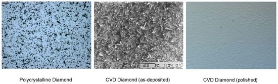
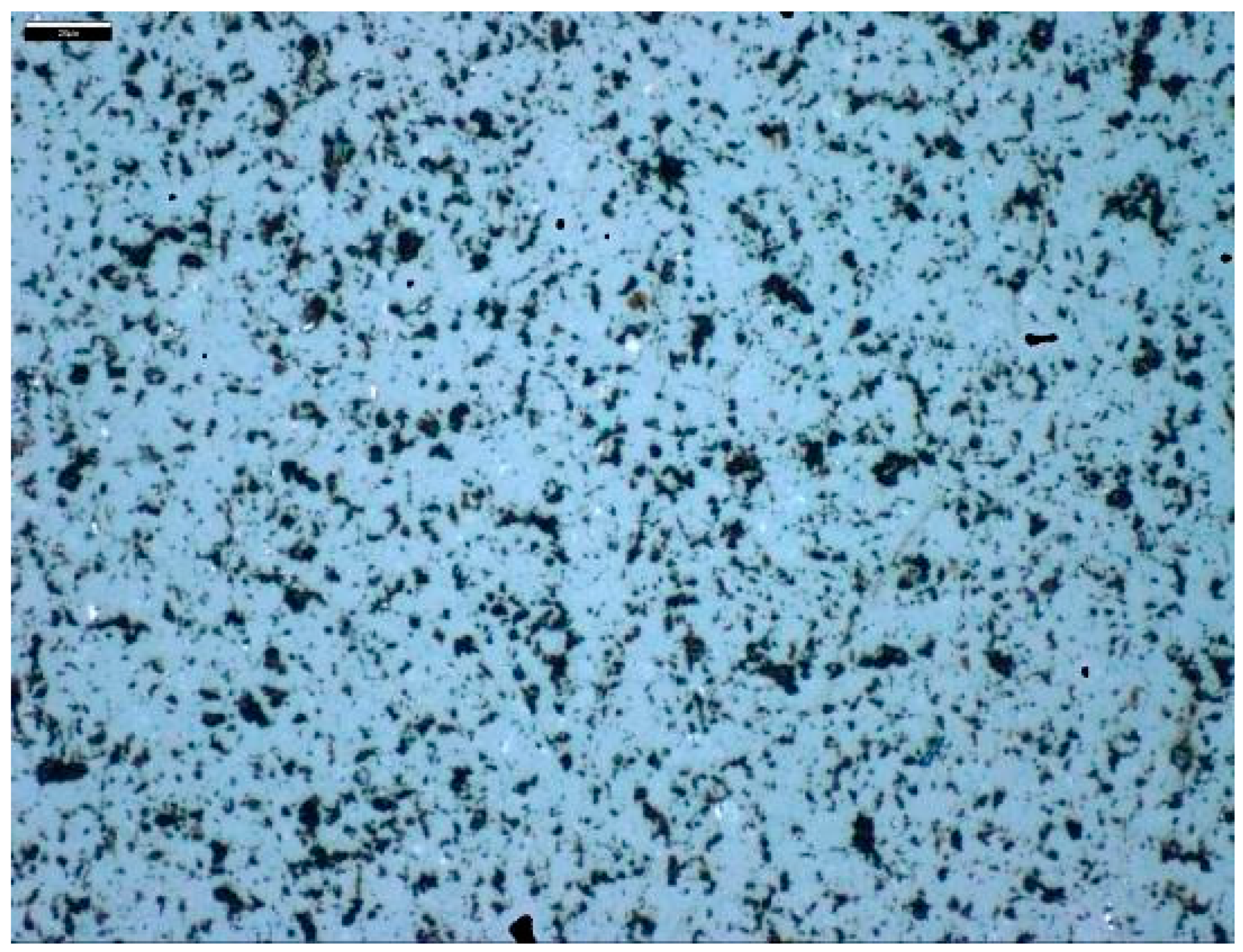
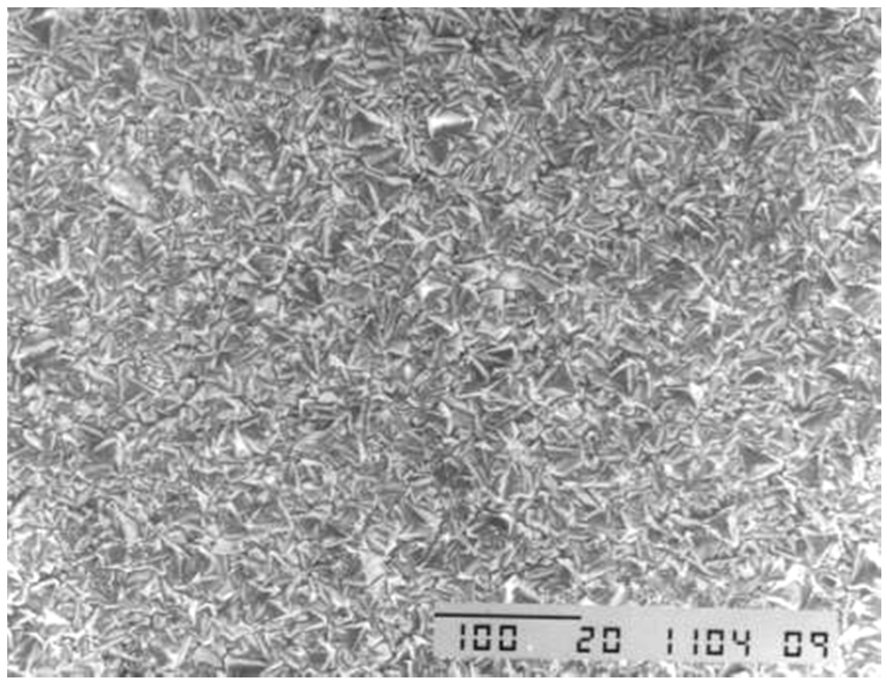
2. Drill Bits
2.1. Geology of Hydrocarbon Reservoirs
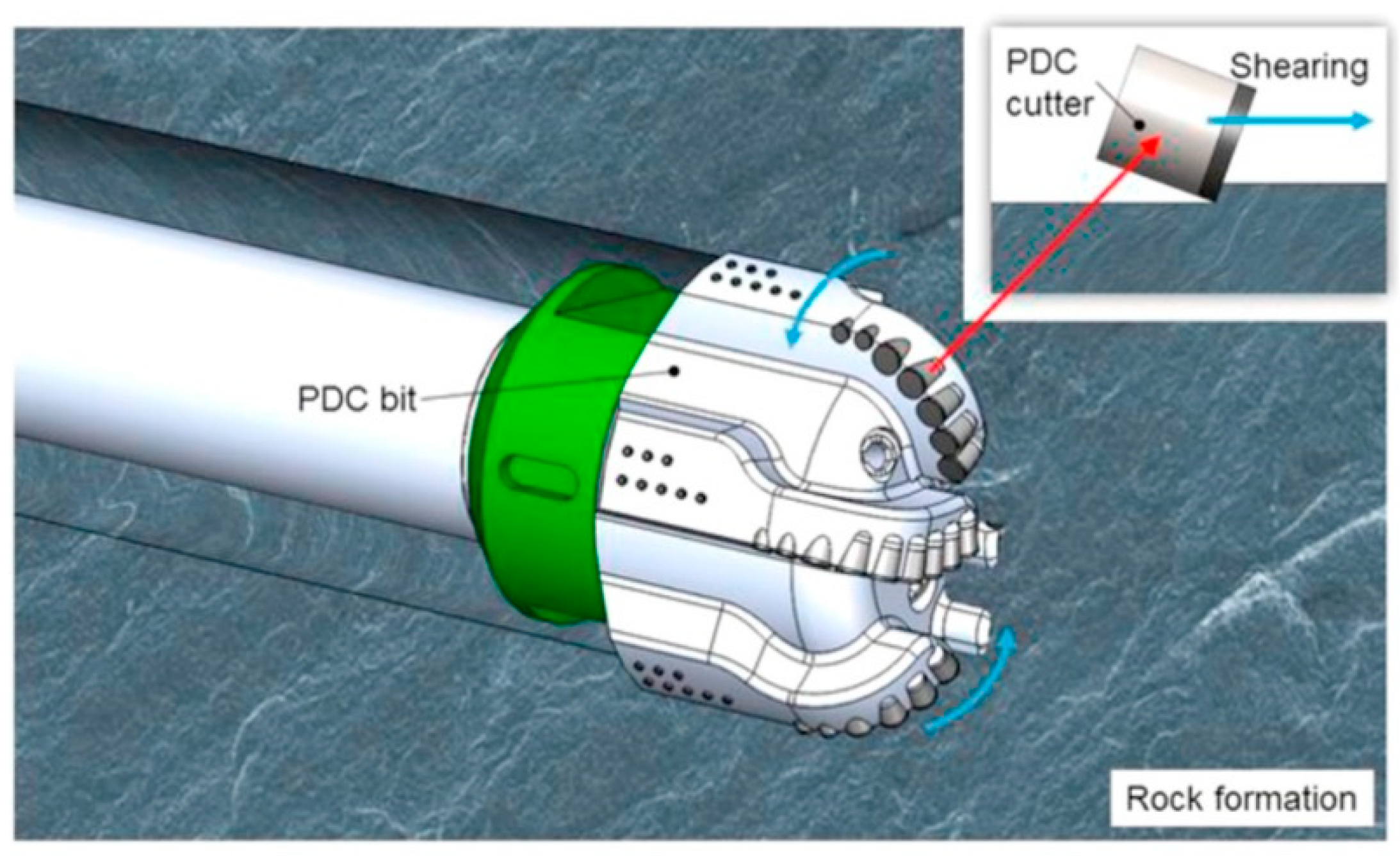
2.2. Drill Bit Design
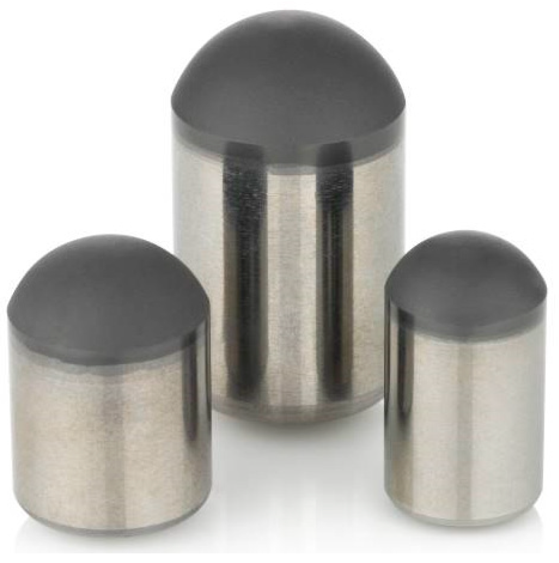
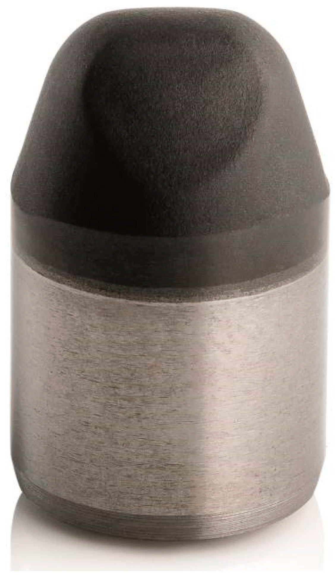
2.3. Tribological Performance of PDC Drill Bits
2.4. Wear Mechanisms of PDC Drill Bits
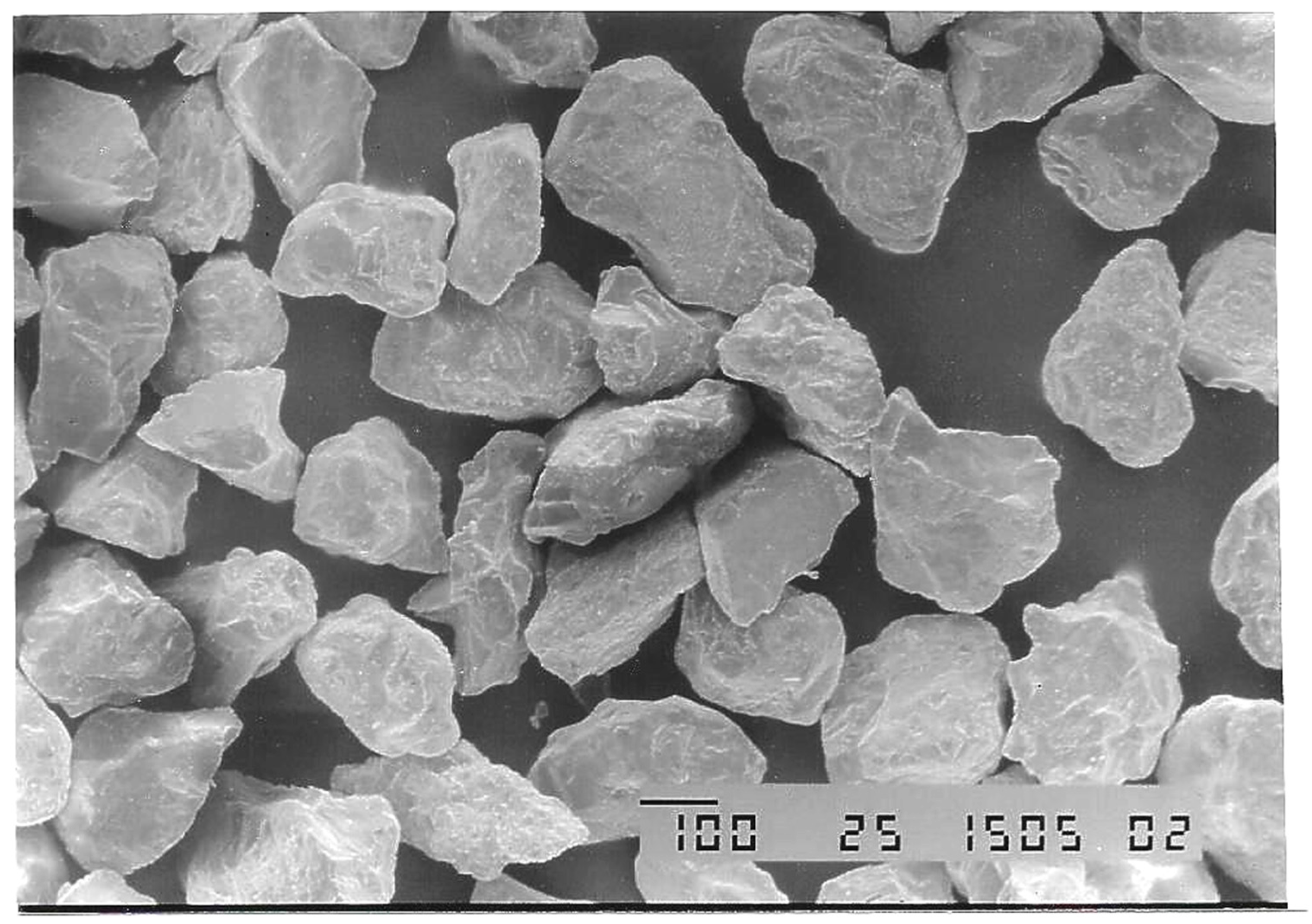
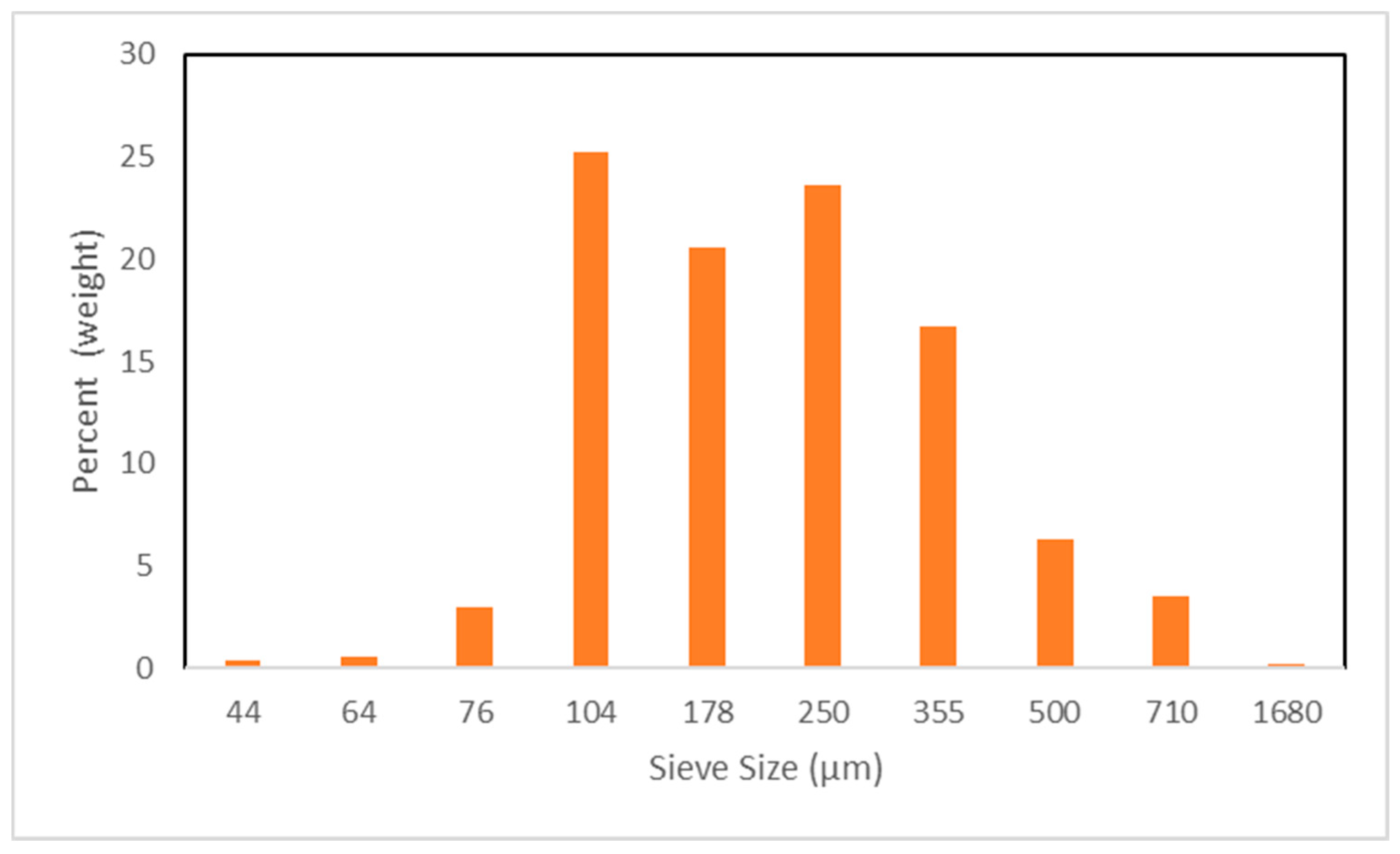
2.4.1. Abrasion
2.4.2. Impact
2.4.3. Thermal Degradation
2.5. Performance of PDC Drill Bits
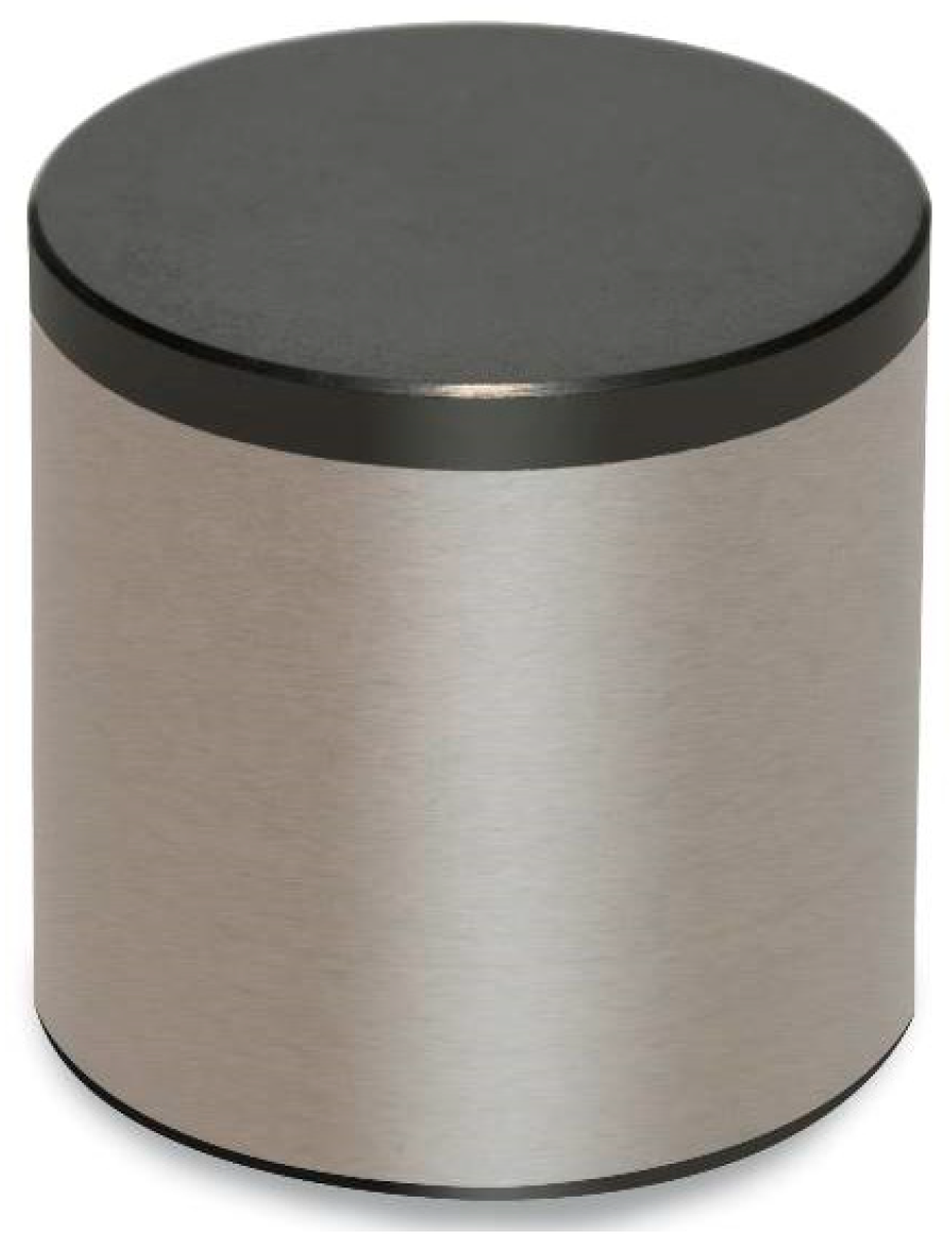
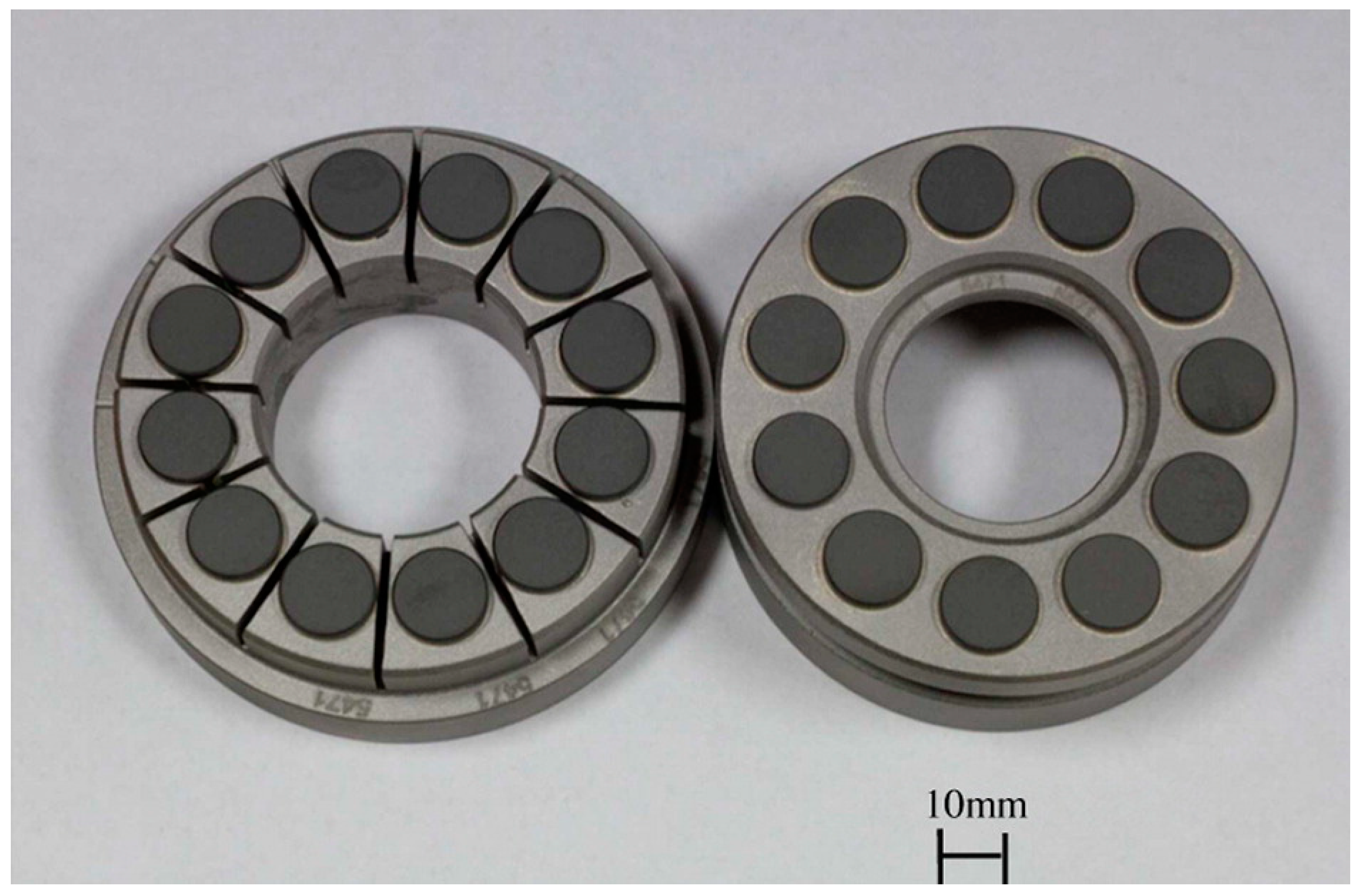
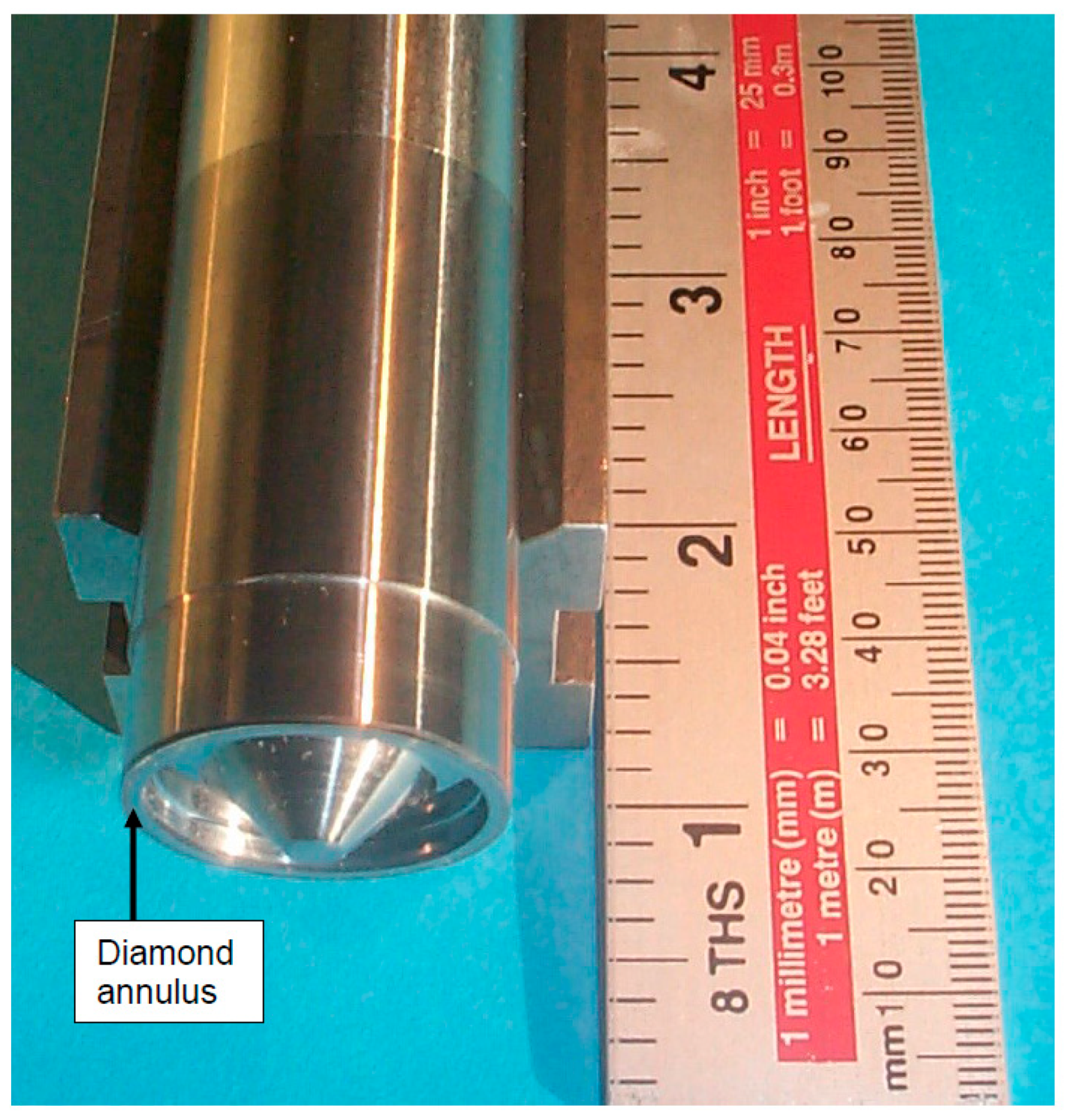
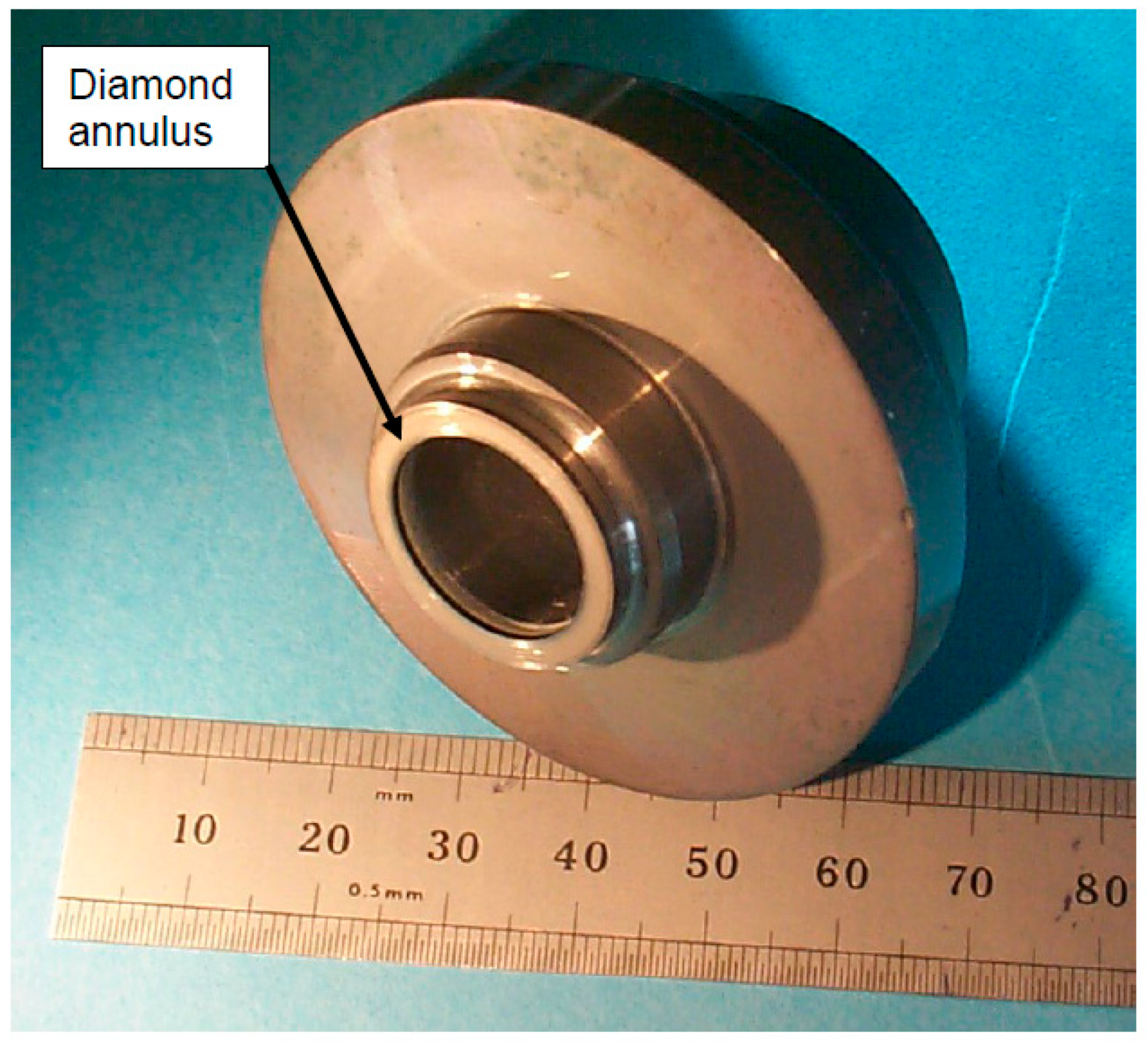
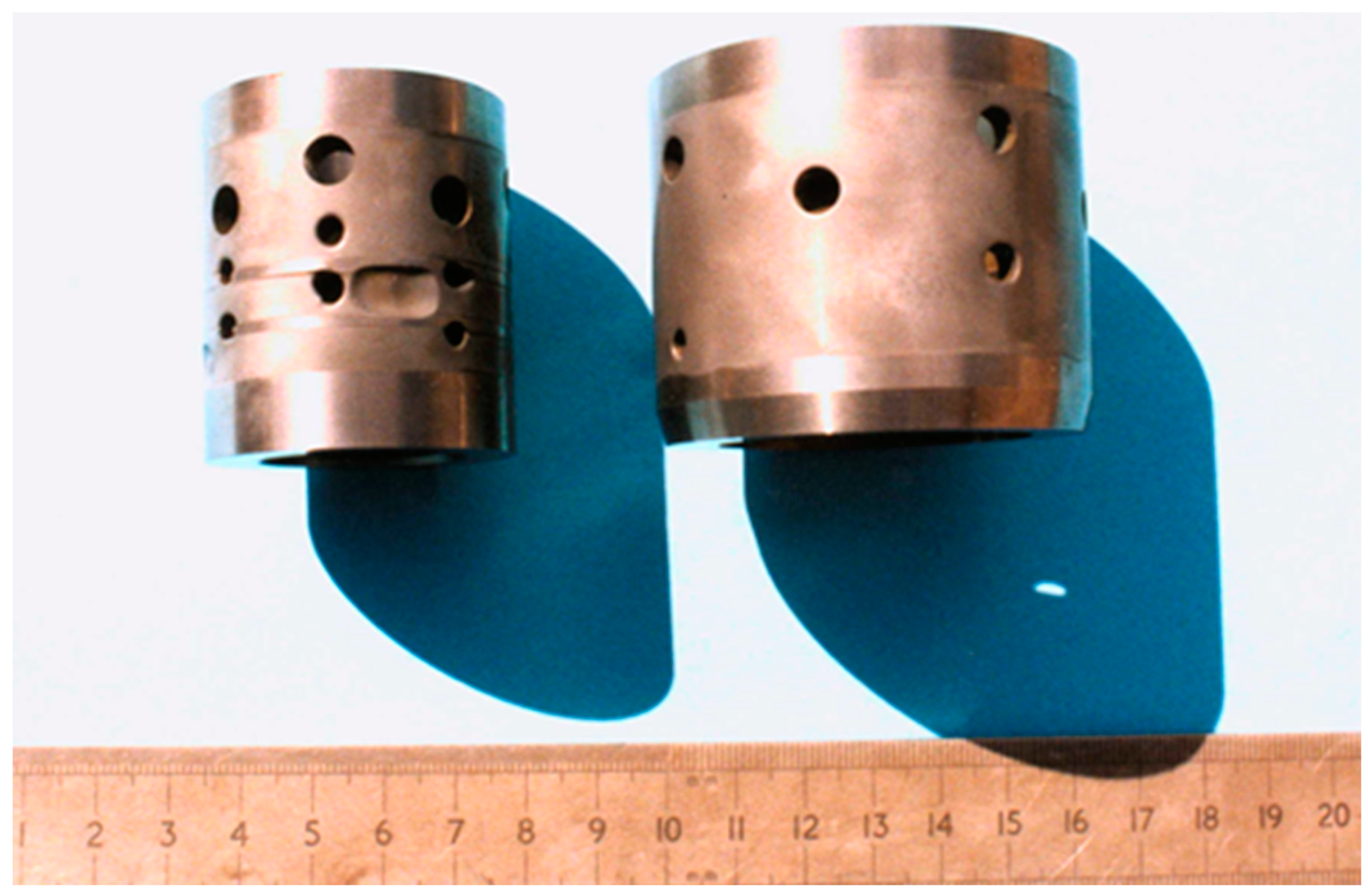
3. Bearings
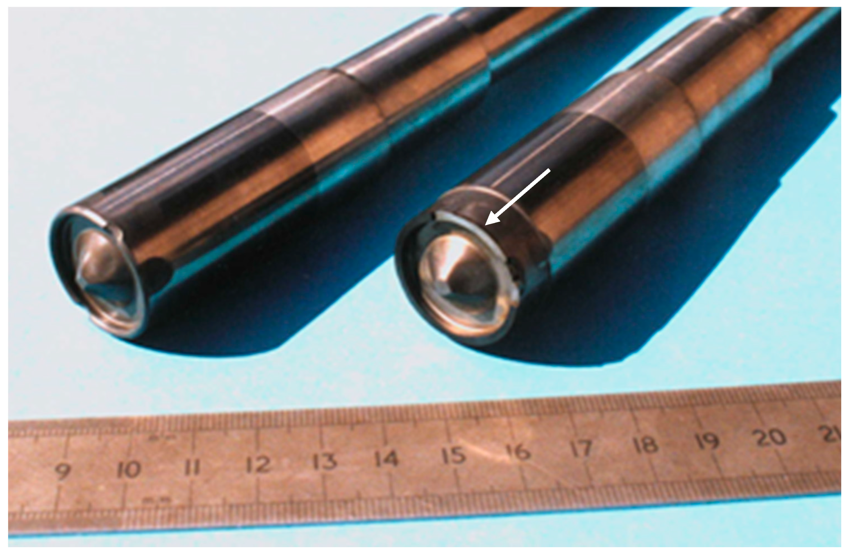
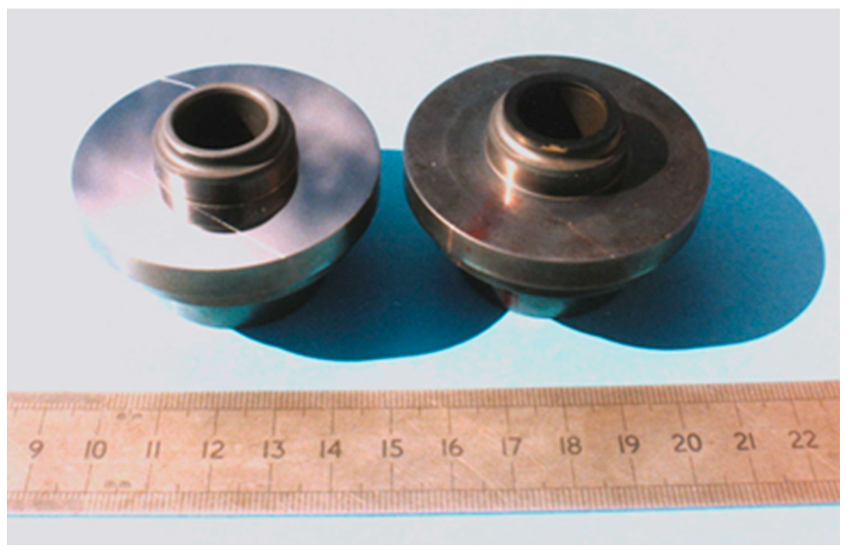
4. Mechanical Seals
5. Control Valves
6. Conclusions
Funding
Acknowledgments
Conflicts of Interest
References
- Papavinasan, S. Corrosion Control in the Oil and Gas Industry; Gulf Professional Publishing: London, UK, 2014. [Google Scholar]
- Wheeler, D.W. CVD diamond: A multifunctional tribological material. In Multifunctional Materials for Tribological Applications; Wood, R.J.K., Ed.; Pan Stanford Publishing Pte. Ltd.: Singapore, 2015; pp. 1–58. [Google Scholar]
- Scott, T.A. The influence of microstructure on the mechanical properties of polycrystalline diamond: A literature review. Adv. Appl. Ceram. 2018, 117, 161–176. [Google Scholar] [CrossRef]
- Walmsley, J.C.; Lang, A.R. Characteristics of diamond regrowth in a synthetic diamond compact. J. Mater. Sci. 1988, 23, 1829–1834. [Google Scholar] [CrossRef]
- Lammer, A. Mechanical properties of polycrystalline diamonds. Mater. Sci. Technol. 1988, 4, 949–955. [Google Scholar] [CrossRef]
- Bruton, G.; Crockett, R.; Taylor, M.; DenBoer, D.; Lund, J.; Fleming, C.; Ford, R.; Garcia, G.; White, A. PDC bit technology for the 21st century. Oilfield Rev. 2014, 26, 48–57. [Google Scholar]
- Wilks, J.; Wilks, E. Properties and Applications of Diamond; Butterworth Heinemann: Oxford, UK, 1991. [Google Scholar]
- Mehan, R.L.; Hibbs, L.E. Thermal degradation of sintered diamond compacts. J. Mater. Sci. 1989, 24, 942–950. [Google Scholar] [CrossRef]
- Liu, C.; Kou, Z.; He, D.; Chen, Y.; Wang, K.; Hui, B.; Zheng, R.; Wang, Y. Effect of removing internal residual metallic phases on wear resistance of polycrystalline diamond compacts. Int. J. Refract. Met. Hard Mater. 2012, 31, 187–191. [Google Scholar] [CrossRef]
- Boland, J.N.; Li, X.S. Microstructural characterisation and wear behaviour of diamond composite materials. Materials 2010, 3, 1390–1419. [Google Scholar] [CrossRef]
- May, P.W. Diamond thin films: A 21st century material. Philos. Trans. R. Soc. Lond. A 2000, 358, 473–495. [Google Scholar] [CrossRef]
- Yan, G.; Yue, W.; Meng, D.; Lin, F.; Wu, Z.; Wang, C. Wear performance and mechanisms of ultrahard polycrystalline diamond composite material grinded against granite. Int. J. Refract. Met. Hard Mater. 2016, 54, 46–53. [Google Scholar] [CrossRef]
- Field, J.E. The mechanical and strength properties of diamond. Rep. Prog. Phys. 2012, 75, 126505. [Google Scholar] [CrossRef] [PubMed]
- Jianxin, D.; Hui, Z.; Ze, W.; Aihua, L. Friction and wear behaviour of polycrystalline diamond at temperatures up to 700 °C. Int. J. Refract. Met. Hard Mater. 2011, 29, 631–638. [Google Scholar] [CrossRef]
- Hess, P. The mechanical properties of various chemical vapor deposition diamond structures compared to the ideal single crystal. J. Appl. Phys. 2012, 111, 051101. [Google Scholar] [CrossRef]
- Telling, R.H.; Field, J.E. The erosion of diamond, sapphire and zinc sulphide by quartz particles. Wear 1999, 233–235, 666–673. [Google Scholar] [CrossRef]
- Drory, M.D.; Dauskardt, R.H.; Kant, A.; Ritchie, R.O. Fracture of synthetic diamond. J. Appl. Phys. 1995, 78, 3083–3088. [Google Scholar] [CrossRef]
- Sussmann, R.S.; Brandon, J.R.; Scarsbrook, G.A.; Sweeney, C.G.; Valentine, T.J.; Whitehead, A.J.; Wort, C.J.H. Properties of bulk polycrystalline CVD diamond. Diamond Relat. Mater. 1994, 3, 303–312. [Google Scholar] [CrossRef]
- Davies, A.R.; Field, J.E.; Pickles, C.S.J. Strength of free-standing chemically vapour-deposited diamond measured by a range of techniques. Philos. Mag. 2003, 83, 4059–4070. [Google Scholar] [CrossRef]
- Field, J.E. The Properties of Natural and Synthetic Diamond; Academic Press: London, UK, 1992. [Google Scholar]
- Twitchen, D.J.; Pickles, C.S.J.; Coe, S.E.; Sussmann, R.S.; Hall, C.E. Thermal conductivity measurements on CVD diamond. Diamond Relat. Mater. 2001, 10, 731–735. [Google Scholar] [CrossRef]
- Wort, C.J.H.; Sweeney, C.G.; Cooper, M.A.; Scarsbrook, G.A.; Sussmann, R.S. Thermal properties of bulk polycrystalline CVD diamond. Diamond Relat. Mater. 1994, 3, 1158–1167. [Google Scholar] [CrossRef]
- Boart Longyear. Data Sheets for Tungsten Carbide Grades; Boart Longyear: Salt Lake City, UT, USA, 1998. [Google Scholar]
- Beste, U. On the Nature of Cemented Carbide Wear in Rock Drilling. Ph.D. Thesis, University of Uppsala, Uppsala, Sweden, 2004. [Google Scholar]
- Mpagazehe, J.N.; Queiruga, A.F.; Higgs, C.F. Towards an understanding of the drilling process for fossil fuel energy: A continuum-discrete approach. Tribol. Int. 2013, 59, 273–283. [Google Scholar] [CrossRef]
- Macdonald, K.A.; Bjune, J.V. Failure analysis of drillstrings. Eng. Fail. Anal. 2007, 14, 1641–1666. [Google Scholar] [CrossRef]
- Beste, U.; Jacobson, S. Micro scale hardness distribution of rock types related to rock drill wear. Wear 2003, 254, 1147–1154. [Google Scholar] [CrossRef]
- Bobko, C.; Ulm, F.J. The nano-mechanical morphology of shale. Mech. Mater. 2008, 40, 318–337. [Google Scholar] [CrossRef]
- Zhu, W.; Hughes, J.J.; Bicanic, N.; Pearce, C.J. Nanoindentation mapping of mechanical properties of cement paste and natural rocks. Mater. Charact. 2007, 58, 1189–1198. [Google Scholar] [CrossRef]
- Shukla, P.; Kumar, V.; Curtis, M.; Sondergeld, C.H.; Rai, C.S. Nanoindentation studies on shales. Presented at 47th US Rock Mechanics/Geomechanics Symposium, San Francisco, CA, USA, 23–26 June 2013. [Google Scholar]
- Eliyahu, M.; Emmanuel, S.; Day-Stirrat, R.J.; Macaulay, C.I. Mechanical properties of organic matter in shales mapped at the nanometer scale. Mar. Petrol. Geol. 2015, 59, 294–304. [Google Scholar] [CrossRef]
- Liu, K.; Ostadhassan, M.; Bubach, B. Applications of nano-indentation methods to estimate nanoscale mechanical properties of shale reservoir rocks. J. Nat. Gas Sci. Eng. 2016, 35, 1310–1319. [Google Scholar] [CrossRef]
- Liu, K.; Ostadhassan, M. Microstructural and geomechanical analysis of Bakken shale at nanoscale. J. Petrol. Sci. Eng. 2017, 153, 133–144. [Google Scholar] [CrossRef]
- Liu, K.; Ostadhassan, M.; Bubach, B.; Ling, K.; Tokhmechi, B.; Robert, D. Statistical grid nanoindentation analysis to estimate macro-mechanical properties of the Bakken shale. J. Nat. Gas Sci. Eng. 2018, 53, 181–190. [Google Scholar] [CrossRef]
- Heinrichs, J.; Olsson, M.; Jacobson, S. Surface degradation of cemented carbides in scratching contact with granite and diamond–the roles of microstructure and composition. Wear 2015, 342–343, 210–221. [Google Scholar] [CrossRef]
- Han, Q.; Chen, P.; Ma, T. Influencing factor analysis of shale micro-indentation measurement. J. Nat. Gas Sci. Eng. 2015, 27, 641–650. [Google Scholar] [CrossRef]
- Chen, P.; Han, Q.; Ma, T.; Lin, D. The mechanical properties of shale based on micro-indentation test. Petrol. Explor. Dev. 2015, 42, 723–732. [Google Scholar] [CrossRef]
- Cala, M.; Cyran, K.; Kawa, M.; Kolano, M.; Lydzba, D.; Pachnicz, M.; Rajczakowska, M.; Rozanski, A.; Sobotka, M.; Stefaniuk, D.; et al. Identification of microstructural properties of shale by combined use of X-ray micro-CT and nanoindentation tests. Procedia Eng. 2017, 191, 735–743. [Google Scholar] [CrossRef]
- Veytskin, Y.B.; Tammina, V.K.; Bobko, C.P.; Hartley, P.G.; Clennell, M.B.; Dewhurst, D.N.; Dagastine, R.R. Micromechanical characterisation of shales through nanoindentation and energy dispersive X-ray spectrometry. Geomech. Energy Environ. 2017, 9, 21–35. [Google Scholar] [CrossRef]
- Scott, D.E. The History And Impact of Synthetic Diamond Cutters and Diamond Enhanced Inserts on the Oil and Gas Industry. Available online: http://pdc-guru.com/uploads/2/8/7/9/2879895/daw_d-scott_history-and-impact-of-synthetic-diamond-cutters-in-og.pdf (accessed on 19 January 2018).
- Jamison, W.E. Tools for rock drilling. In Wear Control Handbook; Peterson, M.B., Winer, W.O., Eds.; American Society of Mechanical Engineers: New York, NY, USA, 1980; pp. 859–890. [Google Scholar]
- Petrica, M.; Badisch, E.; Peinsitt, T. Abrasive wear mechanisms and their relation to rock properties. Wear 2013, 308, 86–94. [Google Scholar] [CrossRef]
- Belozerov, D. Drill Bits Optimization in the Eldfisk Overburden. Master’s Thesis, University of Stavanger, Stavanger, Norway, 2015. Available online: https://brage.bibsys.no/xmlui/bitstream/handle/11250/301097/Belozerov_Dmitriy.pdf?sequence=1&isAllowed=y (accessed on 8 April 2018).
- Azar, M.; Long, W.; White, A.; Copeland, C.; Hempton, R.; Pak, M. A new approach to fixed cutter bits. Oilfield Rev. 2015, 27, 30–35. [Google Scholar]
- Torrance, A.A. Modelling abrasive wear. Wear 2005, 258, 281–293. [Google Scholar] [CrossRef]
- Misra, A.; Finnie, I.M. An experimental study of three-body abrasive wear. Wear 1983, 85, 57–68. [Google Scholar] [CrossRef]
- Gerk, C.; Yan-Gerk, L.; Wesling, V.; Reiter, R. Highly carbide filled composite materials for the mining and drilling industry. IOP Conf. Ser.: Mater. Sci. Eng. 2016, 118, 012011. [Google Scholar] [CrossRef]
- Albdiry, M.T.; Almensory, M.F. Failure analysis of drillstring in petroleum industry: A review. Eng. Fail. Anal. 2016, 65, 74–85. [Google Scholar] [CrossRef]
- Glowka, D. Development of a Method for Predicting the Performance and Wear of PDC Drill Bits. Sandia National Laboratory Report SAND-86-1745; 1987. Available online: http://prod.sandia.gov/techlib/access-control.cgi/1986/861745.pdf (accessed on 2 April 2018).
- Coomber, N. Diamond Drilling Shows its Sparkle. Available online: https://www.offshore-technology.com/features/feature63772/ (accessed on 8 April 2018).
- Roller Cones vs. Diamonds: A Reversal of Roles. Oil and Gas Journal 2/20/2006. Available online: https://www.ogj.com/articles/print/volume-104/issue-7/supplement-to-oil-gas-journal/advances-in-drill-bit-technology/roller-cones-vs-diamonds-a-reversal-of-roles.html (accessed on 8 April 2018).
- Yahiaoui, M.; Gerbaud, L.; Paris, J.-Y.; Denape, J.; Dourfaye, A. A study on PDC drill bits quality. Wear 2013, 298–299, 32–41. [Google Scholar] [CrossRef]
- Menand, S.; Gerbaud, L.; Dourfaye, A. PDC Bit Technology Improvements Increase Efficiency, Bit Life; Drilling Contractor: Houston, TX, USA, March/April 2005; pp. 52–54. [Google Scholar]
- Che, D.; Zhu, W.-L.; Ehmann, K.F. Chipping and crushing mechanisms in orthogonal rock cutting. Int. J. Mech. Sci. 2016, 119, 224–236. [Google Scholar] [CrossRef]
- Che, D.; Ehmann, K. Experimental study of force responses in polycrystalline diamond face turning of rock. Int. J. Rock Mech. Min. Sci. 2014, 72, 80–91. [Google Scholar] [CrossRef]
- Geoffroy, H.; Minh, D.N.; Maitournam, H.; Bergues, J.; Putot, C. Evaluation of drilling parameters of a PDC bit. In Advances in Rock Mechanics; Lin, Y., Ed.; World Scientific Publishing Co. Pte. Ptd.: Singapore, 1998; pp. 301–314. [Google Scholar]
- Wamsley, W.H., Jr.; Ford, R. Introduction to Roller-Cone and Polycrystalline Diamond Drill Bits. In Petroleum Engineering Handbook, Vol II: Drilling Engineering; Lake, L.W., Ed.; Society of Petroleum Engineers: Richardson, TX, USA, 2006; pp. 221–264. [Google Scholar]
- Clark, I.E.; Bex, P.A. The use of PCD for petroleum and mining drilling. Ind. Diamond Rev. 1999, 59, 43–49. [Google Scholar]
- Williams, J.L.; Thompson, A.I. An Analysis of the Performance of PDC Hybrid Drill Bits. In Proceedings of the SPE/IADC Drilling Conference, New Orleans, LA, USA, 15–18 March 1987; Society of Petroleum Engineers: Richardson, TX, USA, 1997. [Google Scholar]
- Dougherty, P.S.M.; Pudjoprawoto, R.; Higgs, C.F., III. Bit cutter-on-rock tribometry: Analysing friction and rate-of-penetration for deep well drilling substrates. Tribol. Int. 2014, 77, 178–185. [Google Scholar] [CrossRef]
- Dougherty, P.S.M.; Mpagazehe, J.; Shelton, J.; Higgs, C.F., III. Elucidating PDC rock cutting behaviour in dry and aqueous conditions using tribometry. J. Petrol. Sci. Eng. 2015, 133, 529–542. [Google Scholar] [CrossRef]
- Dagrain, F.; Richard, T. On the influence of PDC wear and rock type on friction coefficient and cutting efficiency. In Eurock 2006: Multiphysics Coupling and Long Term Behaviour in Rock Mechanics; CRC Press: Boca Raton, FL, USA, 2006; pp. 577–584. [Google Scholar]
- Ersoy, A.; Waller, M.D. Wear characteristics of PDC in and hybrid core bits in rock drilling. Wear 1995, 188, 150–165. [Google Scholar] [CrossRef]
- Abbas, R.K. A review on the wear of oil drill bits (conventional and the state of the at approaches for wear reduction and quantification). Eng. Fail. Anal. 2018, 90, 554–584. [Google Scholar] [CrossRef]
- Yahiaoui, M.; Paris, J.-Y.; Delbe, K.; Denape, J.; Gerbaud, L.; Dourfaye, A. Independent analyses of cutting and friction forces applied on a single polycrystalline diamond compact cutter. Int. J. Rock Mech. Min. Sci. 2016, 85, 20–26. [Google Scholar] [CrossRef]
- Gant, A.J.; Konyashin, I.; Ries, B.; McKie, A.; Nilen, R.W.N.; Pickles, J. Wear mechanisms of diamond-containing hardmetals in comparison with diamond-based materials. Int. J. Refract. Met. Hard Mater. 2018, 71, 106–114. [Google Scholar] [CrossRef]
- Miess, D.; Rai, G. Fracture toughness and thermal resistance of polycrystalline diamond compacts. Mater. Sci. Eng. A 1996, 209, 270–276. [Google Scholar] [CrossRef]
- Yahiaoui, M.; Paris, J.-Y.; Delbe, K.; Denape, J.; Gerbaud, L.; Colin, C.; Ther, O.; Dourfaye, A. Quality and wear behaviour of graded polycrystalline diamond compact cutters. Int. J. Refract. Met. Hard Mater. 2016, 56, 87–95. [Google Scholar] [CrossRef]
- Kanyanta, V.; Dormer, A.; Murphy, N.; Invankovic, A. Impact fatigue fracture of polycrystalline diamond compact (PDC) cutters and the effect of microstructure. Int. J. Refract. Met. Hard Mater. 2014, 46, 145–151. [Google Scholar] [CrossRef]
- Garcia-Marro, F.; Mestra, A.; Kanyanta, V.; Maweja, K.; Ozbayraktar, S.; Llanes, L. Contact damage and residual strength in polycrystalline diamond (PCD). Diamond Relat. Mater. 2016, 65, 131–136. [Google Scholar] [CrossRef]
- Westraadt, J.E.; Sigalas, I.; Neethling, J.H. Characterisation of thermally degraded polycrystalline diamond. Int. J. Refract. Met. Hard Mater. 2015, 48, 286–292. [Google Scholar] [CrossRef]
- Miyazaki, K.; Ohno, T.; Karasawa, H.; Takahura, S.; Eko, A. Performance evaluation of polycrystalline diamond compact percussion bits through drilling tests. Int. J. Rock Mech. Min. Sci. 2016, 87, 1–7. [Google Scholar] [CrossRef]
- Bellin, F.; Dourfaye, A.; King, W.; Thigpen, M. The Current State of PDC Bit Technology. Part 1; World Oil: Houston, TX, USA, September 2010; pp. 41–46. [Google Scholar]
- Bellin, F.; Dourfaye, A.; King, W.; Thigpen, M. The Current State of PDC Bit Technology. Part 3; World Oil: Houston, TX, USA, November 2010; pp. 67–71. [Google Scholar]
- Field, J.E.; Pickles, C.S.J. Strength, fracture and friction properties of diamond. Diamond Relat. Mater. 1996, 5, 625–634. [Google Scholar] [CrossRef]
- Nagel, D.D. Well Drilling Tool with Diamond Thrust Bearings. U.S. Patent 4,620,601, 4 November 1986. [Google Scholar]
- Knuteson, C.W.; Sexton, T.N.; Cooley, C.H. Wear-in behaviour of polycrystalline diamond thrust bearings. Wear 2011, 271, 2106–2110. [Google Scholar] [CrossRef]
- Geczy, B.A. Thrust Bearing Assembly for a Downhole Drill Motor. U.S. Patent 4,560,014, 24 December 1985. [Google Scholar]
- Sexton, T.N.; Cooley, C.H. Polycrystalline diamond thrust bearings for down-hole oil and gas drilling tools. Wear 2009, 267, 1041–1045. [Google Scholar] [CrossRef]
- Ide, R.C. Hydrodynamic thrust bearings for downhole mud motor use. Presented at American Association of Drilling Engineers National Technical Conference and Exhibition, Houston, TX, USA, 12–14 April 2011. [Google Scholar]
- Hayward, I.P.; Singer, I.L.; Seitzman, L.E. Effect of roughness on the friction of diamond on CVD diamond coatings. Wear 1992, 157, 215–227. [Google Scholar] [CrossRef]
- Bull, S.J.; Chalker, P.R.; Johnston, C.; Moore, V. The effect of roughness on the friction and wear of diamond thin films. Surf. Coat. Technol. 1994, 68–69, 603–610. [Google Scholar] [CrossRef]
- Sumant, A.V.; Krauss, A.R.; Gruen, D.M.; Auciello, O.; Erdemir, A.; Williams, M.; Artiles, A.F.; Adams, W. Ultrananocrystalline diamond film as a wear-resistant and protective coating for mechanical seal applications. Tribol. Trans. 2005, 48, 24–31. [Google Scholar] [CrossRef]
- Abreu, C.S.; Oliviera, F.J.; Belmonte, M.; Fernandes, A.J.S.; Silva, R.F.; Gomes, J.R. Grain size effect on self-mated CVD diamond tribosystems. Wear 2005, 259, 771–778. [Google Scholar] [CrossRef]
- Abreu, C.S.; Amaral, M.; Fernandes, A.J.S.; Oliviera, F.J.; Silva, R.F.; Gomes, J.R. Friction and wear performance of HFCVD nanocrystalline diamond coated silicon nitride ceramics. Diamond Relat. Mater. 2006, 15, 739–744. [Google Scholar] [CrossRef]
- Schade, A.; Rosiwal, S.M.; Singer, R.F. Influence of surface topography of HF-CVD diamond films on self-mated planar sliding contacts in dry environments. Surf. Coat. Technol. 2007, 201, 6197–6205. [Google Scholar] [CrossRef]
- Abreu, C.S.; Salgueiredo, E.; Oliviera, F.J.; Fernandes, A.J.S.; Silva, R.F.; Gomes, J.R. CVD diamond water lubricated tribosystems for high load planar sliding. Wear 2008, 265, 1023–1028. [Google Scholar] [CrossRef]
- Hollman, P.; Bjorkman, H.; Alahelisten, A.; Hogmark, S. Diamond coatings applied to mechanical face seals. Surf. Coat. Technol. 1998, 105, 169–174. [Google Scholar] [CrossRef]
- Neale, M.J. The Tribology Handbook, 2nd ed.; Butterworth-Heinemann: Oxford, UK, 1995. [Google Scholar]
- Parrott, S. Engineering ceramics for aggressive environments. Mat. Mater. 1990, 6, 207–210. [Google Scholar]
- Nau, B.S. Mechanical seal face materials. Proc. Inst. Mech. Eng. Part J J. Eng. Tribol. 1997, 211, 165–183. [Google Scholar] [CrossRef]
- Diamond pump seals launched. Seal. Technol. 2008, 2008, 1. [CrossRef]
- Zou, M.; Green, I. Real-time condition monitoring of mechanical face seal. In Tribology for Energy Conservation; Dowson, D., Taylor, C.M., Childs, T.H.C., Dalmaz, G., Berthier, Y., Flamand, L., Georges, J.M., Lubrecht, A., Eds.; Elsevier Science B.V.: Amsterdam, The Netherlands, 1998; pp. 423–430. [Google Scholar]
- Jones, G.A. On the tribological behaviour of mechanical seal face materials in dry line contact Part I. Mechanical carbon. Wear 2004, 256, 415–432. [Google Scholar] [CrossRef]
- Thorvart, L. The materials key to seal performance. Mater. World 1994, 2, 519–521. [Google Scholar]
- Kelly, P.J.; Arnell, R.D.; Hudson, M.D.; Wilson, A.E.J.; Jones, G. Enhanced mechanical seal performance through CVD diamond films. Vacuum 2001, 61, 61–74. [Google Scholar] [CrossRef]
- Jones, G.A. On the tribological behaviour of mechanical seal face materials in dry line contact Part II. Bulk ceramics, diamond and diamond-like carbon films. Wear 2004, 256, 433–455. [Google Scholar] [CrossRef]
- Tome, M.A.; Fernandes, A.J.S.; Oliveira, F.J.; Silva, R.F.; Carrapichano, J.M. High performance sealing with CVD diamond self-mated rings. Diamond Relat. Mater. 2005, 14, 617–621. [Google Scholar] [CrossRef]
- Mubarok, F.; Carrapichano, J.M.; Almeida, F.A.; Fernandes, A.J.S.; Silva, R.F. Enhanced sealing performance with CVD nanocrystalline diamond films in self-mated mechanical seals. Diamond Relat. Mater. 2008, 17, 1132–1136. [Google Scholar] [CrossRef]
- Kovalchenko, A.M.; Elam, J.W.; Erdemir, A.; Carlisle, J.A.; Auciello, O.; Libera, J.A.; Pellin, M.J.; Gruen, D.M.; Hryn, J.N. Development of ultrananocrystalline diamond (UNCD) coatings for multipurpose mechanical pump seals. Wear 2011, 270, 325–331. [Google Scholar] [CrossRef]
- Diamond faces deliver performance. Seal. Technol. 2007, 2007, 2–3. [CrossRef]
- Diamond wear surfaces optimized for dry running. Seal. Technol. 2010, 2010, 16. [CrossRef]
- UNCD Faces Technical Information; Advanced Diamond Technologies, Inc.: Romeoville, IL, USA, 2018.
- Diamond Coatings for Industrial Components; Advanced Diamond Technologies Inc.: Romeoville, IL, USA, 2018; Available online: http://www.thindiamond.com/wp-content/uploads/2018/04/148732-FINAL-ADT-BROCHURE-RA-vs4.pdf (accessed on 19 June 2018).
- Otschik, J.; Schrufer, A.; Thelke, J.; Kirchhof, M.; Schmaderer, S. Diamond seal faces—The benefits. World Pumps 2010, 18–20. [Google Scholar] [CrossRef]
- Goldschmidt, A.; Gurtler, T. DiamondFace-coated seals ensure pumps run smoothly at remote field in Ecuador. Seal. Technol. 2013, 10–11. [Google Scholar] [CrossRef]
- Walton, I.C.; Atwood, D.C.; Halleck, P.M.; Bianco, L.C.B. Perforating unconsolidated sands: An experimental and theoretical investigation. SPE Drill. Complet. 2002, 17, 141–150. [Google Scholar] [CrossRef]
- Recommended Practice: Managing Sand Production and Erosion; DNV Report DNVGL-RP-0501; DNV GL: Høvik, Norway, August 2015.
- Forder, A.F.; Thew, M.T.; Harrison, D. The erosion of oilfield control valves by turbulent particulate suspensions. In Proceedings of the 2nd International Conference Valves, Actuators and Systems: Problems and Solutions, Cambridge, UK, 14–15 April 1997; Blanford, G., Ed.; Independent Technical Conferences, Bedford. 1997; pp. 191–204. [Google Scholar]
- Haugen, K.; Kvernvold, O.; Ronold, A.; Sandberg, R. Sand erosion of wear-resistant material: Erosion in choke valves. Wear 1995, 186–187, 179–188. [Google Scholar] [CrossRef]
- Wood, R.J.K.; Wheeler, D.W. Erosion of candidate hard surface coatings for valve applications. In Proceedings of the 2nd International Conference Valves, Actuators and Systems: Problems and Solutions, Cambridge, UK, 14–15 April 1997; Blanford, G., Ed.; Independent Technical Conferences, Bedford. 1997; pp. 217–224. [Google Scholar]
- Shipway, P.H.; Hutchings, I.M. The role of particle properties in the erosion of brittle materials. Wear 1996, 193, 105–113. [Google Scholar] [CrossRef]
- Pennefather, R.C.; Hankey, S.E.; Hutchings, R.; Ball, A. Recent observations of the erosion of hard materials. Mater. Sci. Eng. A 1988, 105–106, 389–394. [Google Scholar] [CrossRef]
- Feng, Z.; Tzeng, Y.; Field, J.E. Solid particle impact of CVD diamond films. Thin Solid Films 1992, 212, 35–42. [Google Scholar] [CrossRef]
- Jilbert, G.H.; Pickles, C.S.J.; Coad, E.J.; Field, J.E. Diamond: An erosion resistant aerospace material. In Applications of Diamond Films and Related Materials: 3rd International Conference; National Institute of Standards and Technology: Gaithersburg, MD, USA, 1995; pp. 561–564. [Google Scholar]
- Davies, A.R.; Field, J.E. The solid particle erosion of free-standing CVD diamond. Wear 2002, 252, 96–102. [Google Scholar] [CrossRef]
- Telling, R.H.; Field, J.E. Fracture and erosion of CVD diamond. Diamond Relat. Mater. 1999, 8, 850–854. [Google Scholar] [CrossRef]
- Wheeler, D.W.; Wood, R.J.K. Erosive wear behaviour of thick chemical vapour deposited diamond coatings. Wear 1999, 225–229, 523–536. [Google Scholar] [CrossRef]
- Wheeler, D.W.; Wood, R.J.K. Solid particle erosion of CVD diamond coatings. Wear 1999, 233–235, 306–318. [Google Scholar] [CrossRef]
- Wheeler, D.W.; Wood, R.J.K. Solid particle erosion of diamond coatings under non-normal impact angles. Wear 2001, 250, 795–801. [Google Scholar] [CrossRef]
- Wheeler, D.W.; Wood, R.J.K. CVD diamond: Erosion-resistant hard material. Surf. Eng. 2003, 19, 466–470. [Google Scholar] [CrossRef]
- Wheeler, D.W.; Wood, R.J.K. Erosion damage in diamond coatings by high velocity sand impacts. Philos. Mag. 2007, 87, 5719–5740. [Google Scholar] [CrossRef]
- Wheeler, D.W.; Wood, R.J.K. Fracture of diamond coatings by high velocity sand erosion. Philos. Mag. 2009, 89, 285–310. [Google Scholar] [CrossRef]
- Lu, F.X.; He, Q.; Guo, S.B.; Zhang, F.L.; Tong, Y.M. Sand erosion of freestanding diamond films prepared by DC arcjet. Diamond Relat. Mater. 2010, 19, 936–941. [Google Scholar] [CrossRef]
- Almeida, F.A.; Derkaoui, N.; Oliveira, F.J.; Benedic, F.; Silva, R.F.; Gicquel, A. Erosive wear resistance of NCD coatings produced by pulsed microwave discharges. Diamond Relat. Mater. 2010, 19, 484–488. [Google Scholar] [CrossRef]
- Wang, X.; Zhang, J.; Shen, B.; Zhang, T.; Sun, F. Erosion mechanism of the boron-doped diamond films of different thicknesses. Wear 2014, 312, 1–10. [Google Scholar] [CrossRef]
- Wang, X.; Zhang, J.; Shen, B.; Zhang, T.; Sun, F. Fracture and solid particle erosion of micro-crystalline, nano-crystalline and boron-doped diamond films. Int. J. Refract. Met. Hard Mater. 2014, 45, 31–40. [Google Scholar] [CrossRef]
- Wang, X.; Shen, X.; Sun, F.; Shen, B. Mechanical properties and solid particle erosion of MCD films synthesized using different carbon sources by BE-HFCVD. Int. J. Refract. Met. Hard Mater. 2016, 54, 370–377. [Google Scholar] [CrossRef]
- Wheeler, D.W.; Wood, R.J.K.; Harrison, D.; Smith, E. Application of diamond to enhance choke valve life in erosive duties. Wear 2006, 261, 1087–1094. [Google Scholar] [CrossRef]
- Wise, J.L. Geometry and Material Choices Govern Hard-Rock Drilling Performance of PDC Drag Cutters. In Proceedings of the Alaska Rocks 2005 40th U.S. Symposium on Rock Mechanics (USRMS), Anchorage, AK, USA, 25–29 June 2005. [Google Scholar]
- Eagle Bergmann’s new-generation Cartex cartridge seals benefits from DiamondFace coating. Seal. Technol. 2012, 2012, 1. [CrossRef]
- Available online: http://eagleburgmannnow.com/ebnow/index.cfm/stories/diamond-coating-increases-service-life-of-mechanical-seals/ (accessed on 5 December 2012).


| PCD | CVD Diamond | WC-6Co | |
|---|---|---|---|
| Hardness (GPa) | 53–57 [12] | 60–110 [15] | 14–17 [23] |
| Elastic modulus (GPa) | 750–950 [13] | 500–1200 [15] | 620 [23] |
| Fracture toughness (MPa √m) | 6.9–8.9 [5] | 5.0–9.0 [15,16,17,18] | 9.9–12.7 [23] |
| Poisson’s ratio | 0.07–0.09 [5] | 0.07–0.08 [13] | 0.21 [23] |
| Fracture strength (MPa) | 444–1815 [3] | 300–1200 [19] | 2000–2200 [23] |
| Density (kg·m−3) | 3430–4240 [13] | 3520 [20] | 14900 [23] |
| Thermal conductivity (W·m−1·K−1) | 700 [14] | 1646–2220 [21] | 95–122 [24] |
| Coefficient of thermal expansion (×10−6 K−1) | 0.9–1.2 [14] | 0.8–1.2 [22] | 5.4 [23] |
| Rock Type | Mean Hardness (GPa) |
|---|---|
| Calcite | 1.91 [24] |
| Shale | 2.25 [34] |
| Granite | 7.85 [24] |
| Sandstone | 9.91 [24] |
| Quartz | 11.97 [24] |
| Stationary Ring | Rotating Ring | Coefficient of Friction (in Water) |
|---|---|---|
| UNCD | SiC | 0.018–0.04 |
| UNCD | Carbon | 0.06–0.10 |
| SiC | SiC | >0.18 |
| SiC | Carbon | 0.08–0.10 |
© 2018 by the author. Licensee MDPI, Basel, Switzerland. This article is an open access article distributed under the terms and conditions of the Creative Commons Attribution (CC BY) license (http://creativecommons.org/licenses/by/4.0/).
Share and Cite
Wheeler, D.W. Applications of Diamond to Improve Tribological Performance in the Oil and Gas Industry. Lubricants 2018, 6, 84. https://doi.org/10.3390/lubricants6030084
Wheeler DW. Applications of Diamond to Improve Tribological Performance in the Oil and Gas Industry. Lubricants. 2018; 6(3):84. https://doi.org/10.3390/lubricants6030084
Chicago/Turabian StyleWheeler, David W. 2018. "Applications of Diamond to Improve Tribological Performance in the Oil and Gas Industry" Lubricants 6, no. 3: 84. https://doi.org/10.3390/lubricants6030084
APA StyleWheeler, D. W. (2018). Applications of Diamond to Improve Tribological Performance in the Oil and Gas Industry. Lubricants, 6(3), 84. https://doi.org/10.3390/lubricants6030084