Effect of Surface Texturing Parameters on the Lubrication Characteristics of an Axial Piston Pump Valve Plate


Abstract
:
1. Introduction
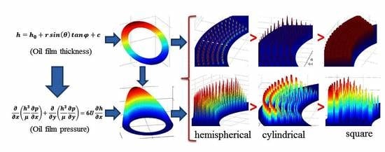
2. Establishment and Solution of Microtexture of Valve Plate
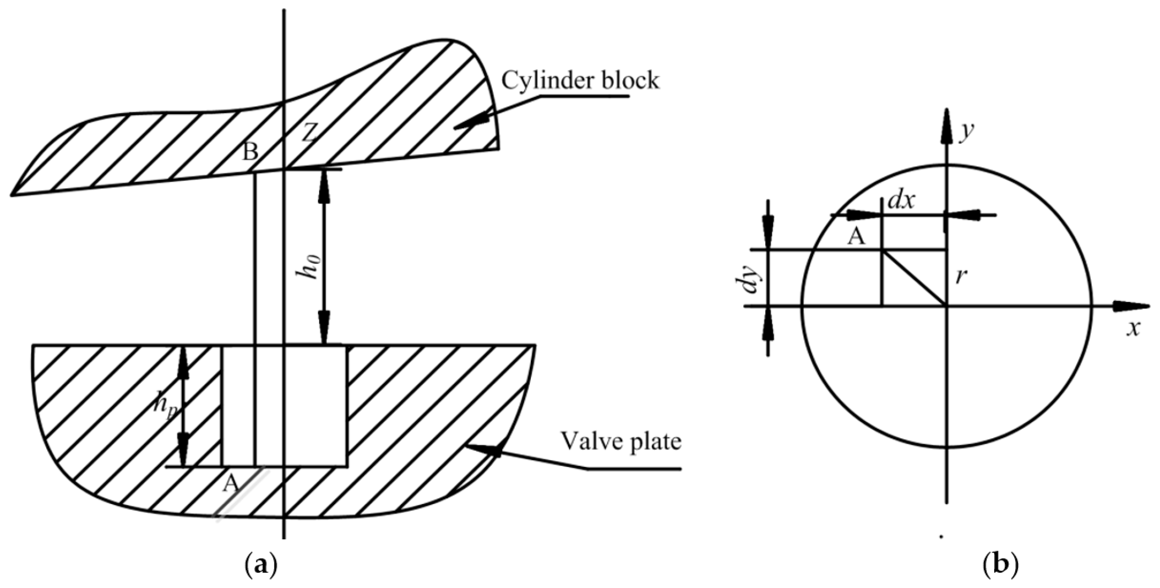
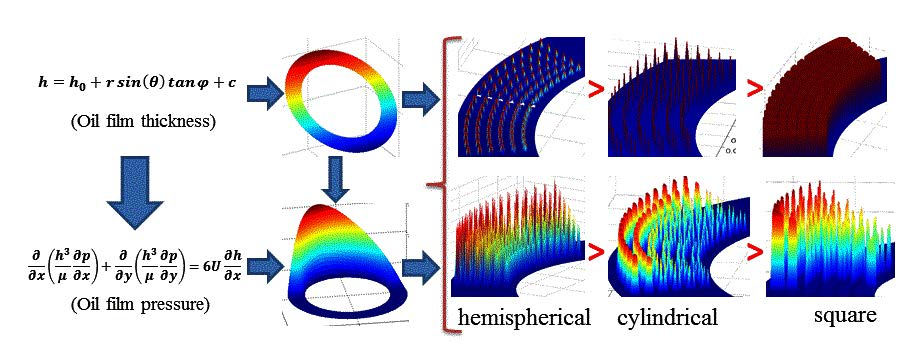
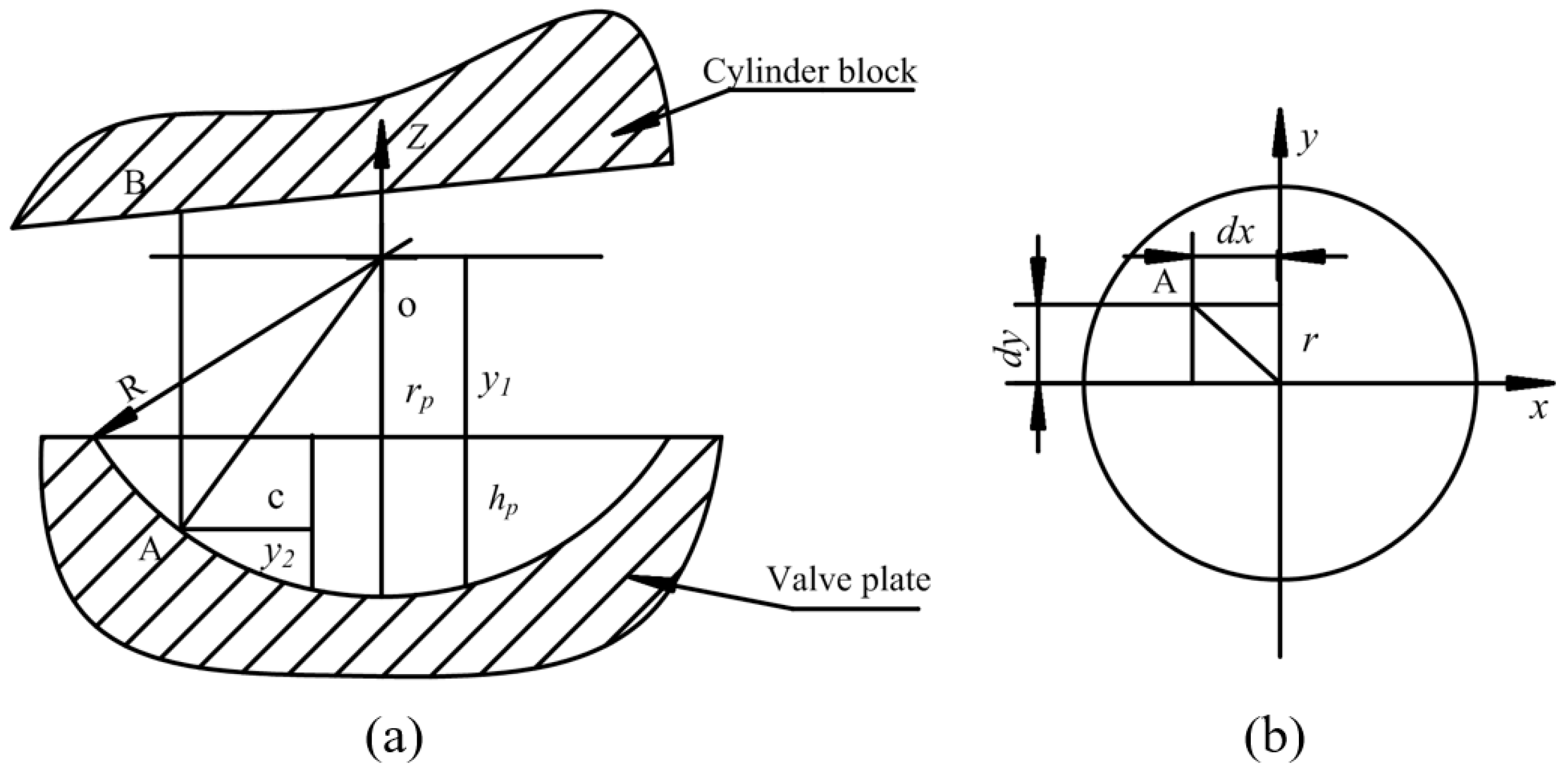
2.1. Micro-Hemispherical Texture Oil Film Morphological Equation Modeling of Valve Plate
2.2. Micro-Cylindrical Texture Oil Film Morphological Equation Modeling for Valve Plate
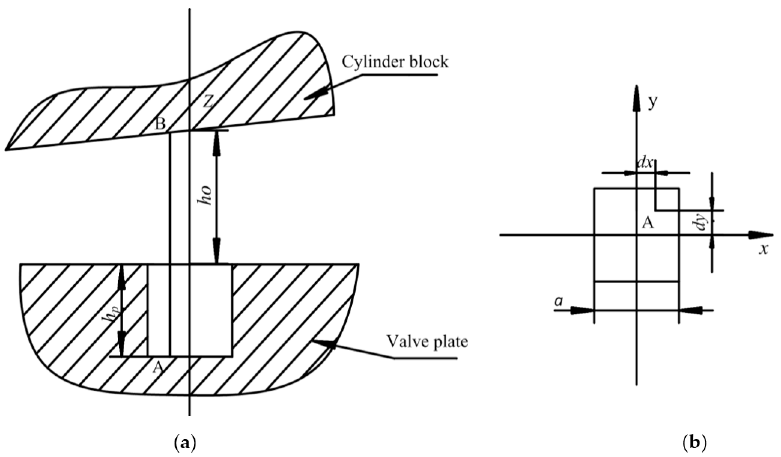
2.3. Micro-Square Texture Oil Film Morphological Equation Modeling for Valve Plate
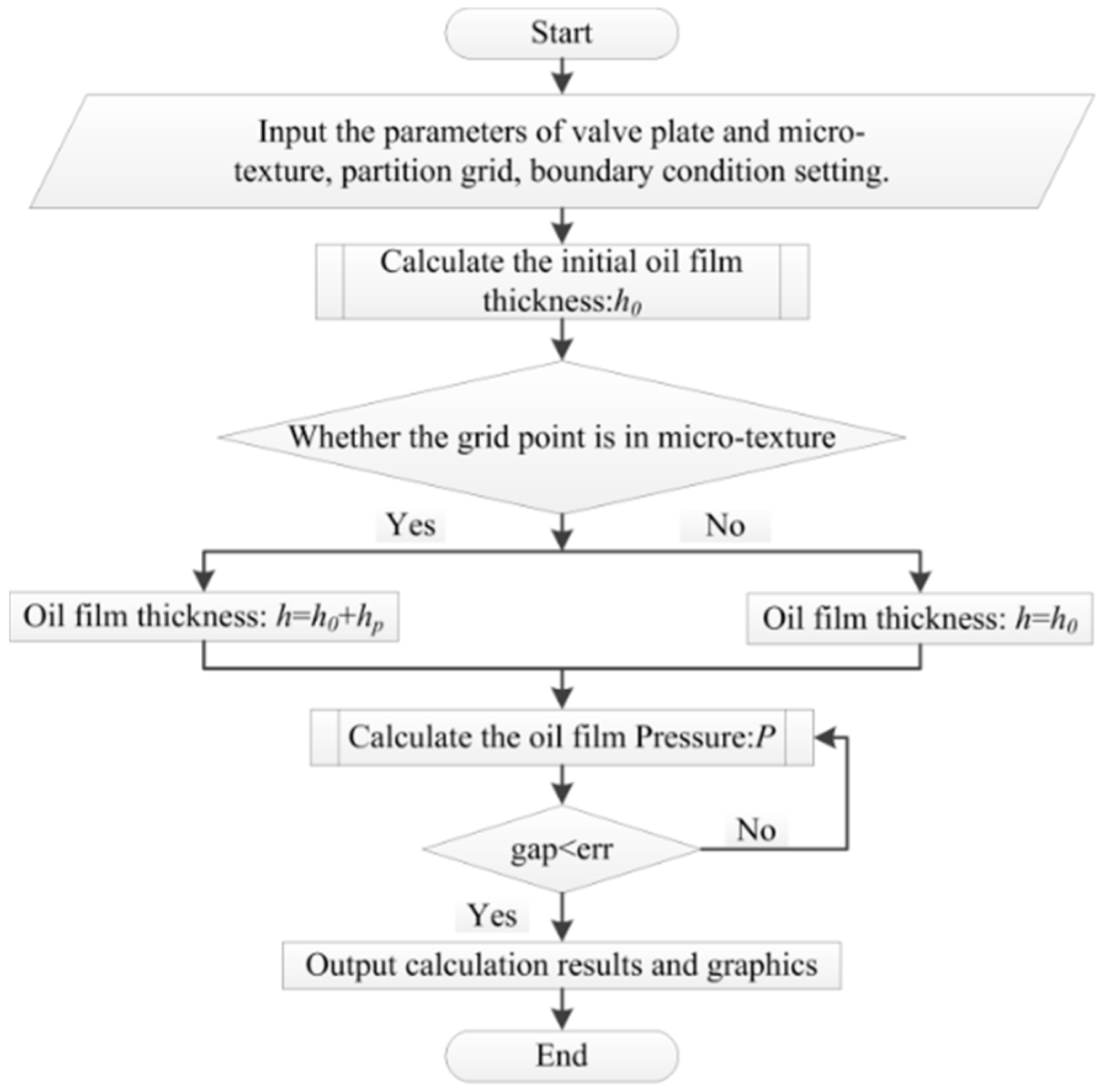
2.4. Solution of the Microtexture Model for Valve Plate
3. Oil Film Thickness and Pressure Distribution of a Valve Plate without Microtexture
3.1. Solution of Oil Film Pressure of a Valve Plate without Microtexture
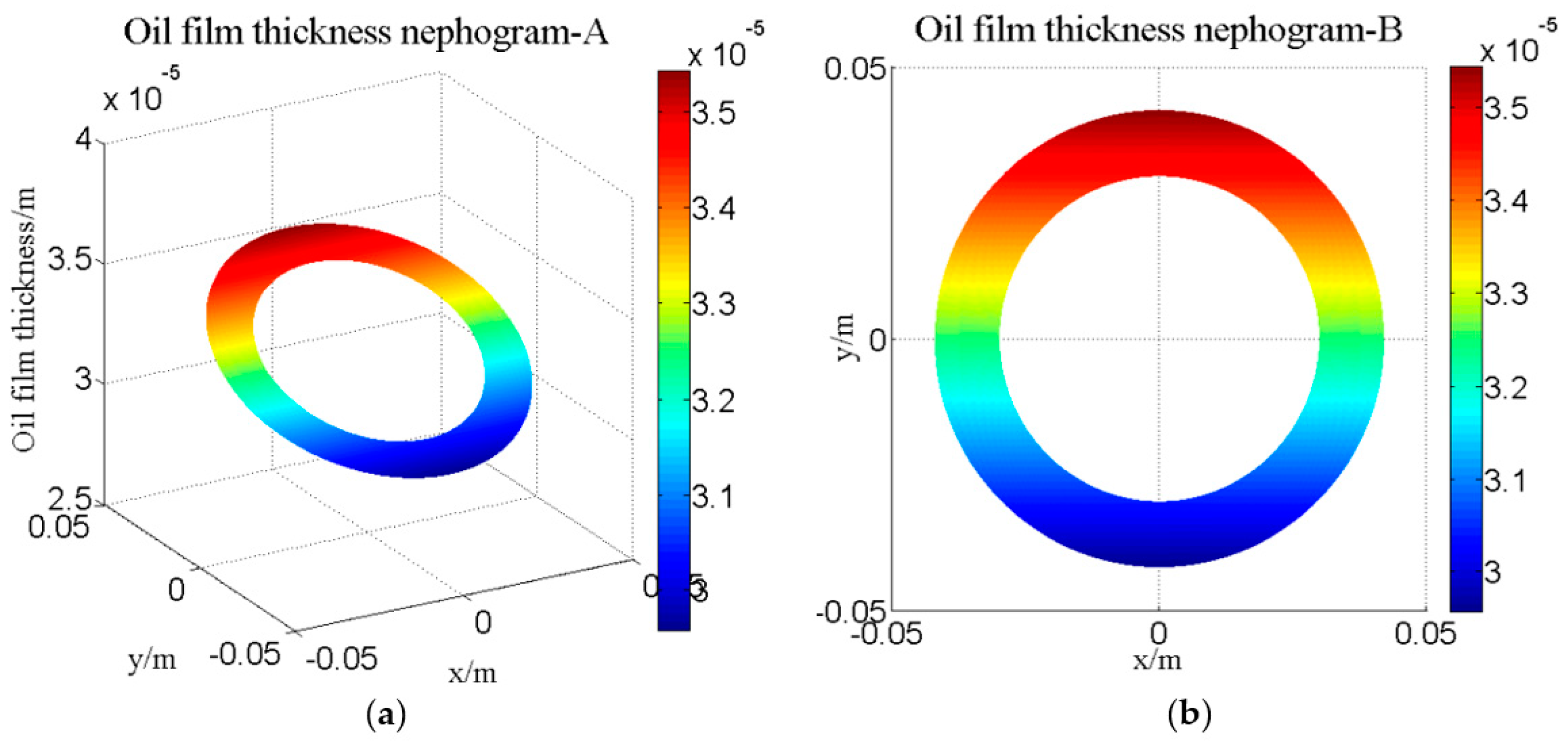
3.2. Distribution of Oil Film Thickness across the Valve Plate
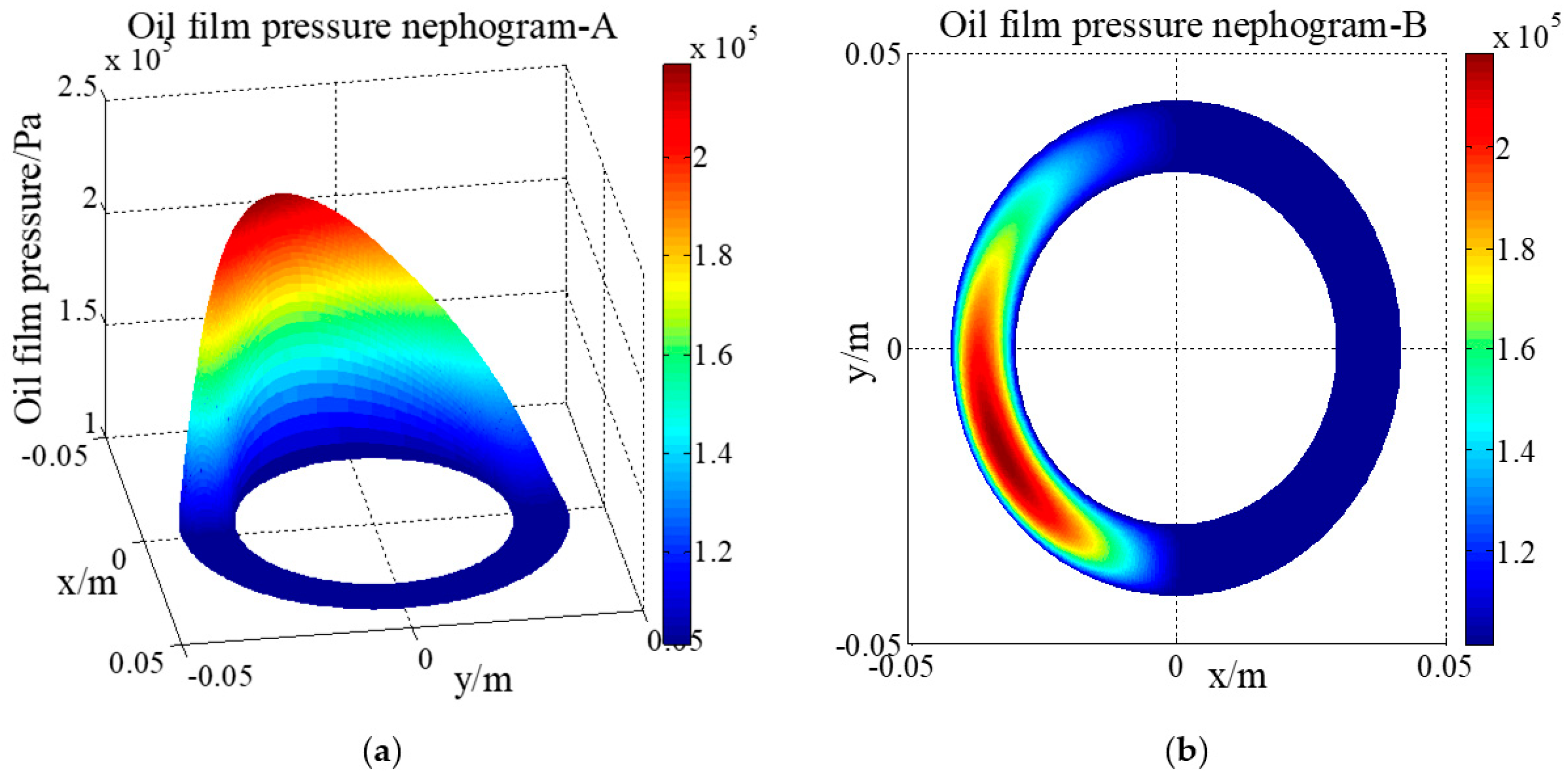
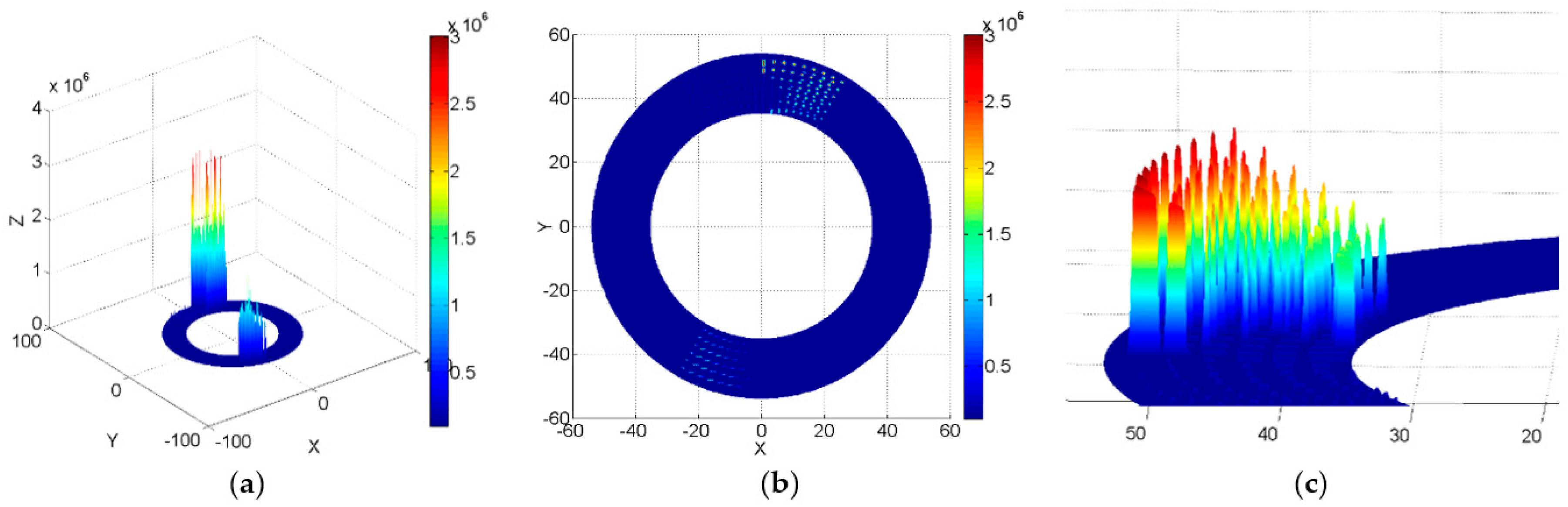
3.3. Distribution of Oil Film Pressure across the Valve Plate
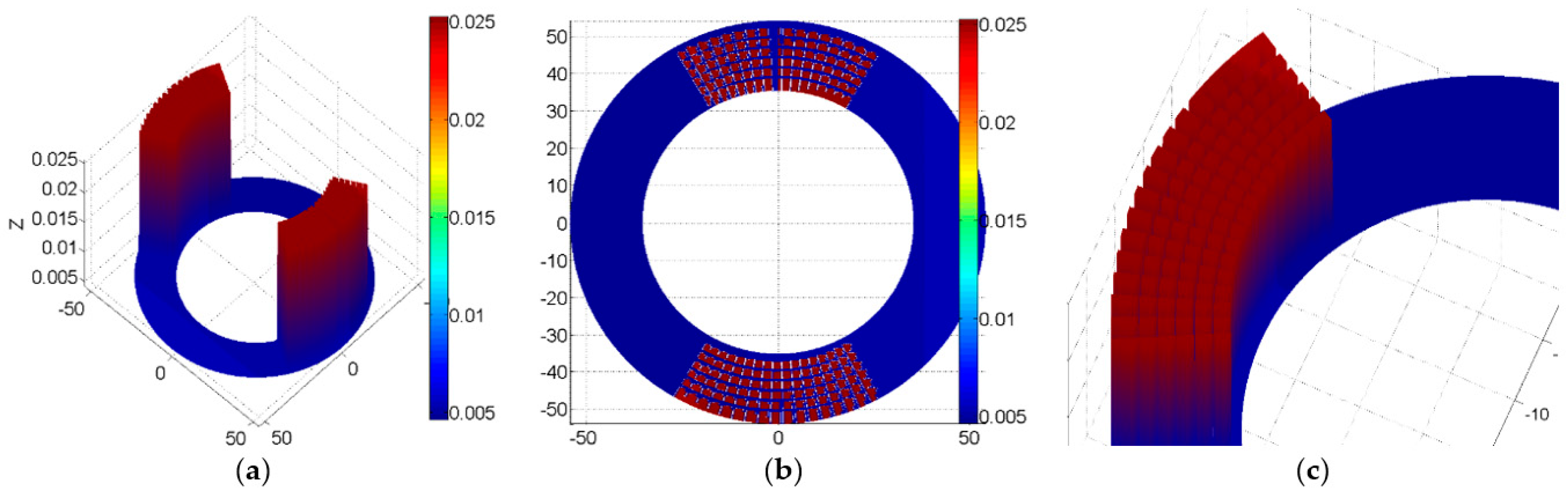
4. Oil Film Thickness and Pressure Distribution of a Microtextured Valve Plate
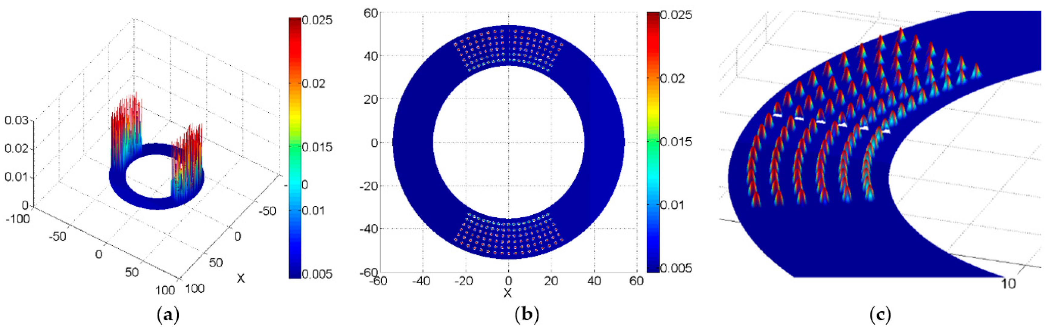
4.1. Oil Film Thickness and Pressure Distribution of Valve Plate with Micro-Hemispherical Texture
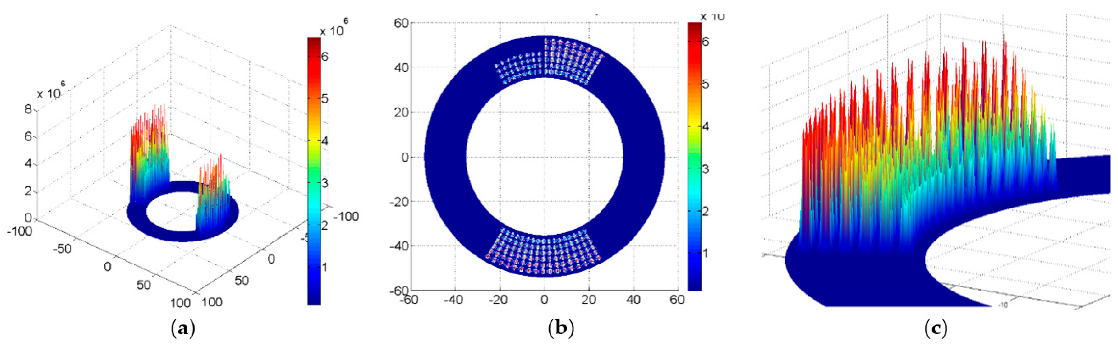
4.2. Oil Film Thickness and Pressure Distribution of a Valve Plate with Micro-Cylindrical Texture
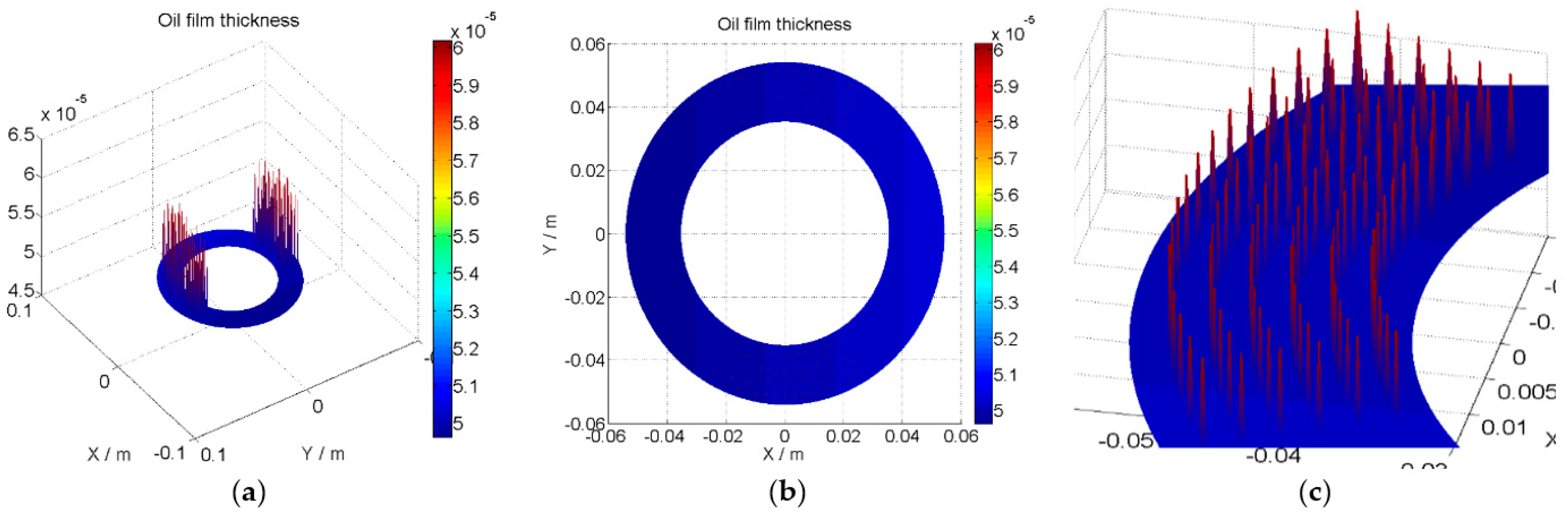
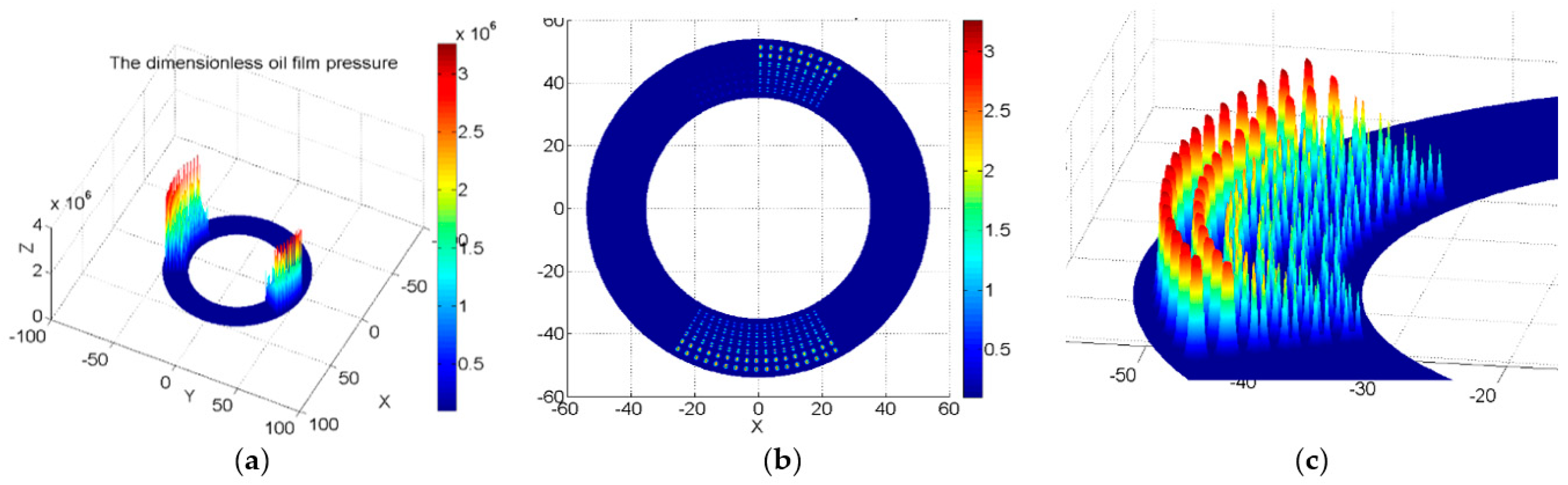
4.3. Oil Film Thickness and Pressure Distribution of a Valve Plate with a Micro-Square Texture
4.4. Comparison of the Oil Film Pressure Lubrication Characteristics of Different Microtexture
5. The Influence of Microtexture Radius on the Performance of the Valve Plate
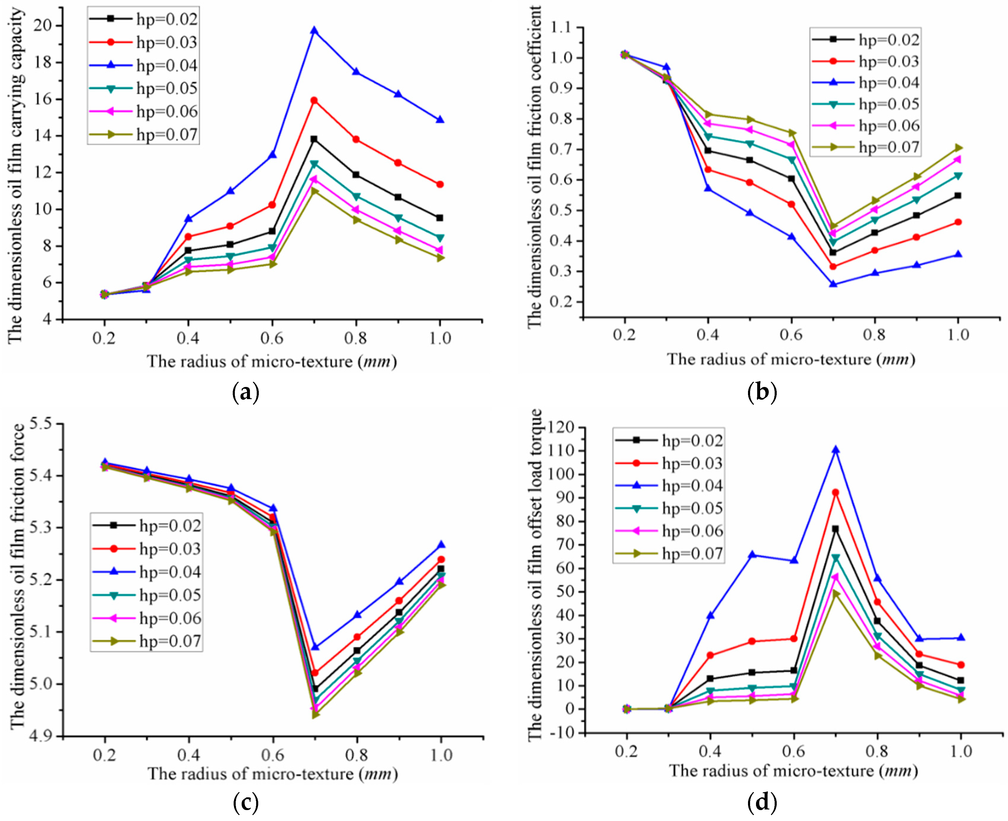
5.1. The Influence of Micro-Hemispherical Texture Radius on the Performance of the Valve Plate
- The oil film carrying capacity was 5.36 (minimum) when the radius was 0.2 mm, while the oil film carrying capacity was 19.72 (maximum) when the radius was 0.7 mm and the depth was 0.04 mm. Thus, the value could be increased by 14.36 compared to the minimum carrying capacity.
- The oil film friction coefficient was 1.0117 (maximum) when the radius was 0.2 mm, while the oil film friction coefficient was 0.2571 (minimum) when the radius was 0.7 mm and the depth was 0.04 mm. The value thus increased by 0.7546 compared to the minimum oil film friction coefficient.
- The oil film friction force was 5.4252 (maximum) when the radius was 0.2 mm, and 5.0701 (manimum) when the radius was 0.7 mm and the depth was 0.07 mm. The value thus increased by 0.3551 compared to the minimum oil film friction coefficient.
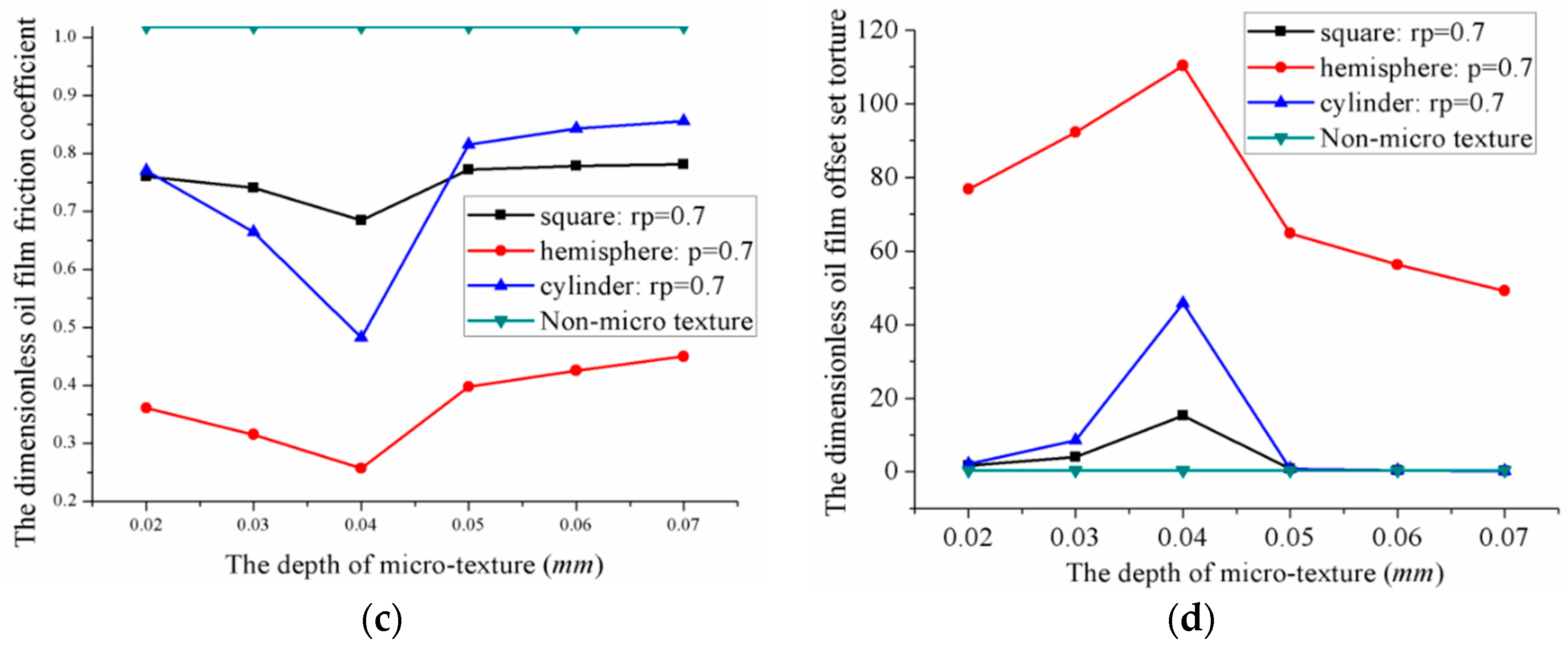
- The oil film offset load torque was 0.001433 (minimum) when the radius of micro-hemispherical texture was 0.2 mm, and 110.41 (maximum) when the radius was 0.7 mm and the depth was 0.04 mm. The optimal value thus increased by 110.4086 compared with the minimum oil film offset load torque.
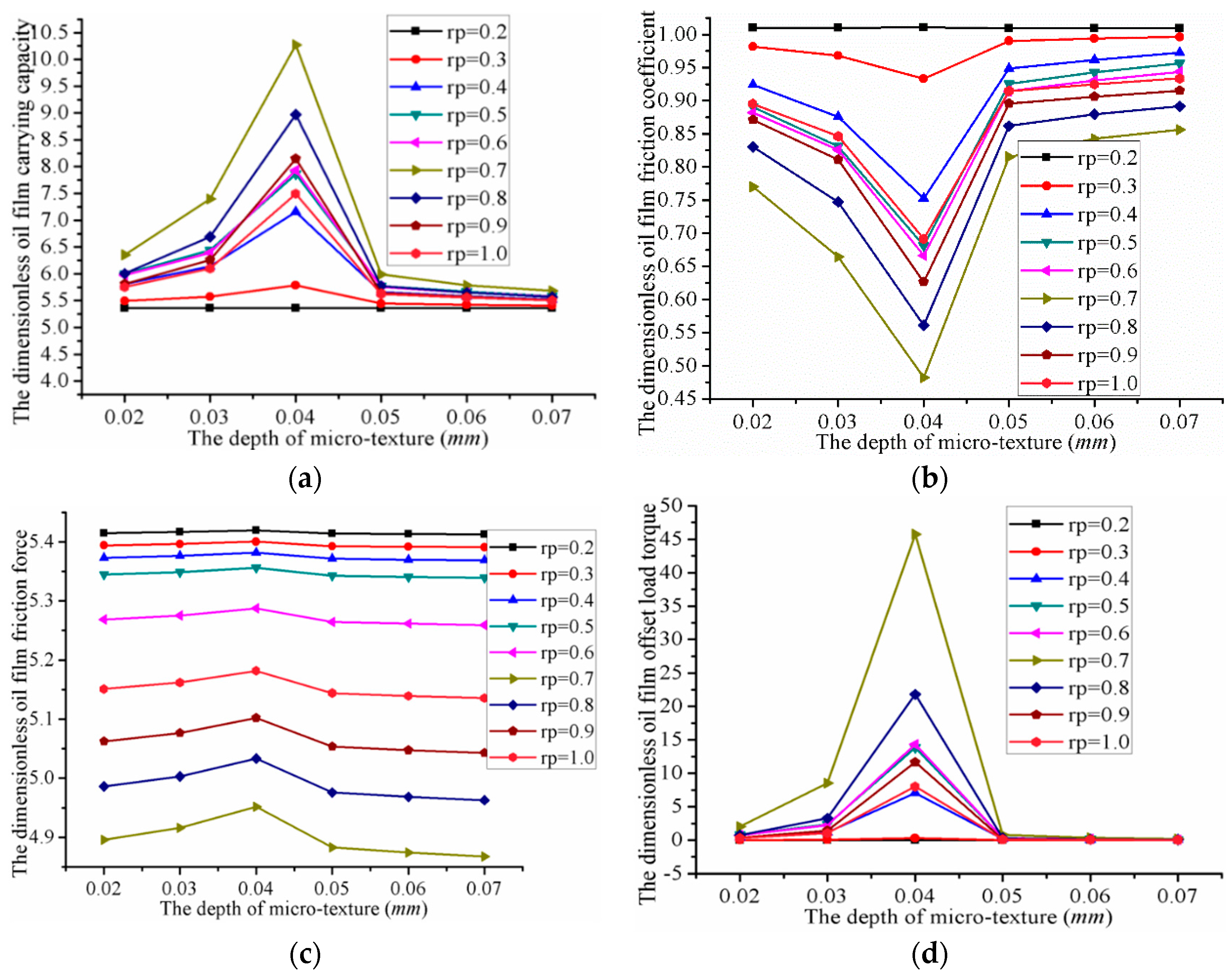
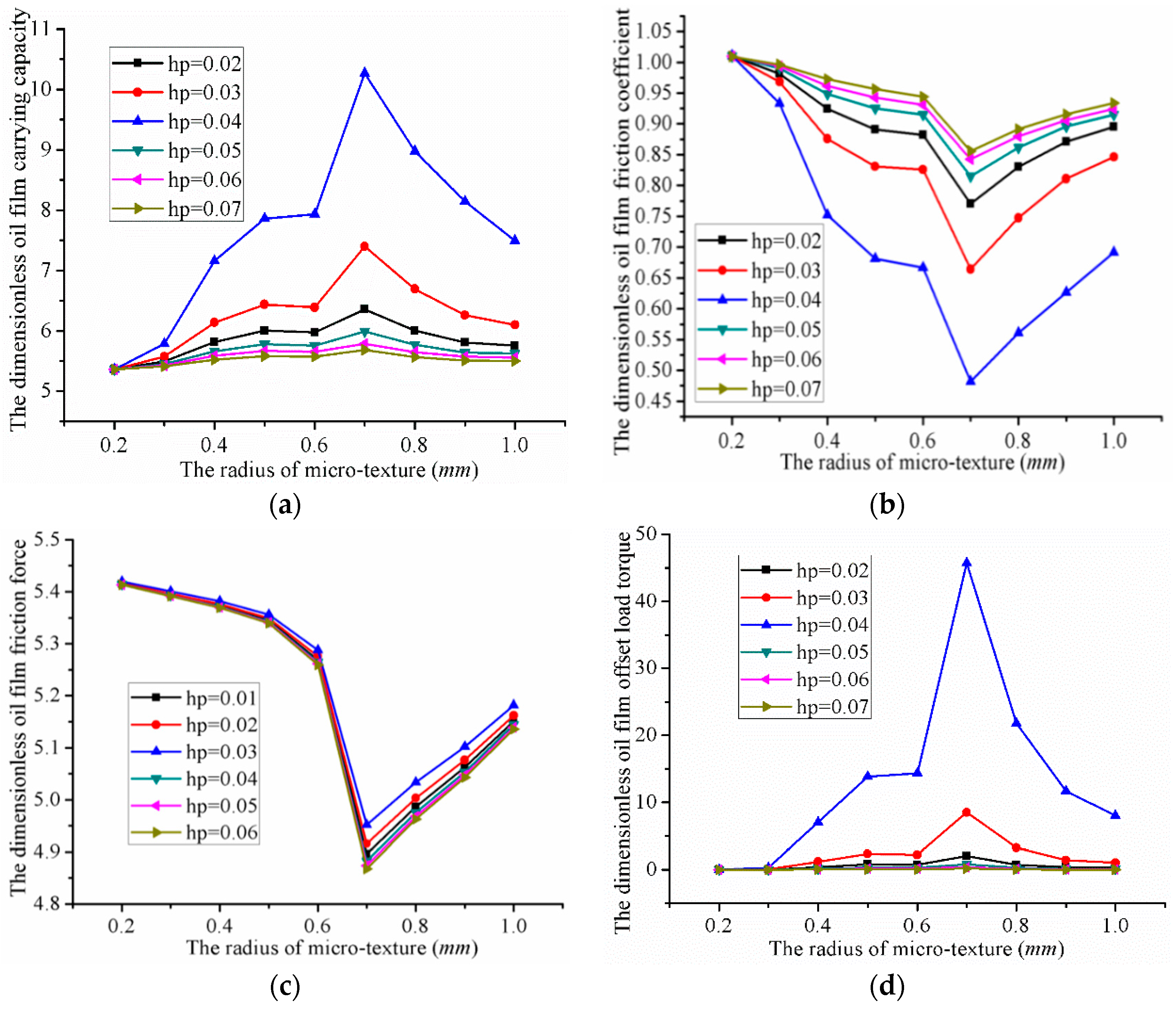
5.2. The Influence of Micro-Cylindrical Texture’s Radius on the Performance of Valve Plate
- The oil film carrying capacity was 5.36 (minimum) when the radius was 0.2 mm, and 10.37 (maximum) when the radius was 0.7 mm and the depth was 0.04 mm. Thus, the value could be increased by 5.01 compared with the minimum oil carrying capacity.
- The oil film friction coefficient is 1.0106 (maximum) when the radius was 0.2 mm, and 0.4821 (minimum) when the radius was 0.7 mm and the depth was 0.04 mm. The value thus increased by 0.5285 compared with the minimum friction coefficient.
- The oil film friction force was 5.4193 (maximum) when the radius was 0.2 mm, and 4.9517 (minimum) when the radius was 0.7 mm and the depth was 0.06 mm. The value could thus be increased by 0.4676 compared with the minimum friction force.
- The oil film offset load torque reached a minimum of 0.001436 when the radius was 0.2 mm, and a maximum of 45.748 when the radius was 0.7 mm and the depth was 0.04 mm. The maximum value was thus 45.7466 greater than the minimum.
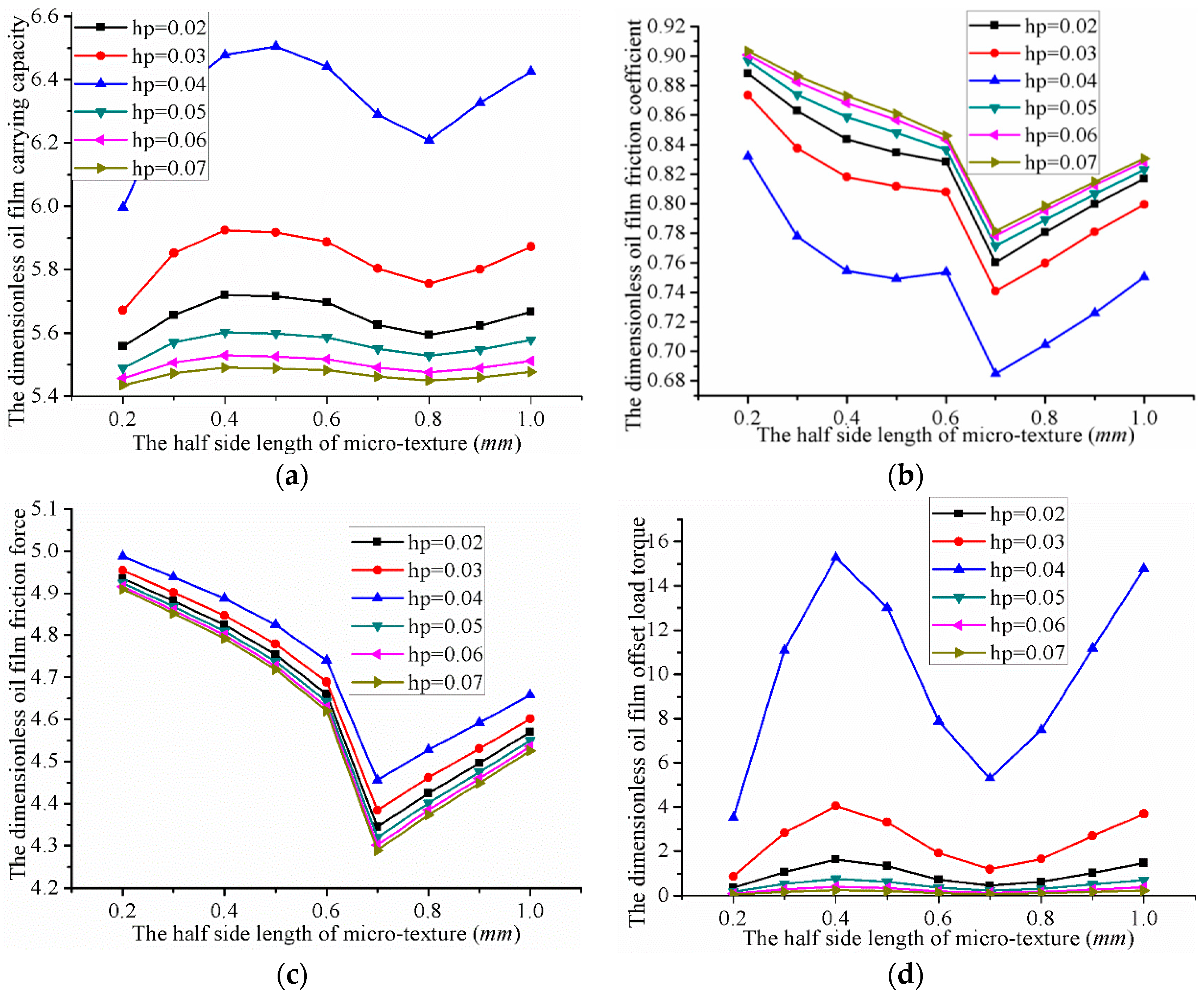
5.3. The Influence of Micro-Square Texture’s Half Side Length on the Performance of Valve Plate
- The oil film carrying capacity was 5.43 (minimum) when the half-side length is 0.2 mm, and 6.50 (maximum) when the half-side length was 0.5 mm and the depth was 0.04 mm. The maximum value was thus 1.07 higher than the minimum carrying capacity.
- The oil film friction coefficient was 0.9069 (maximum) when the half-side length is 0.2 mm, and 0.6848 (minimum) when the half-side length was 0.7 mm and the depth was 0.04 mm. The value could thus be increased by 0.2221 compared to the minimum.
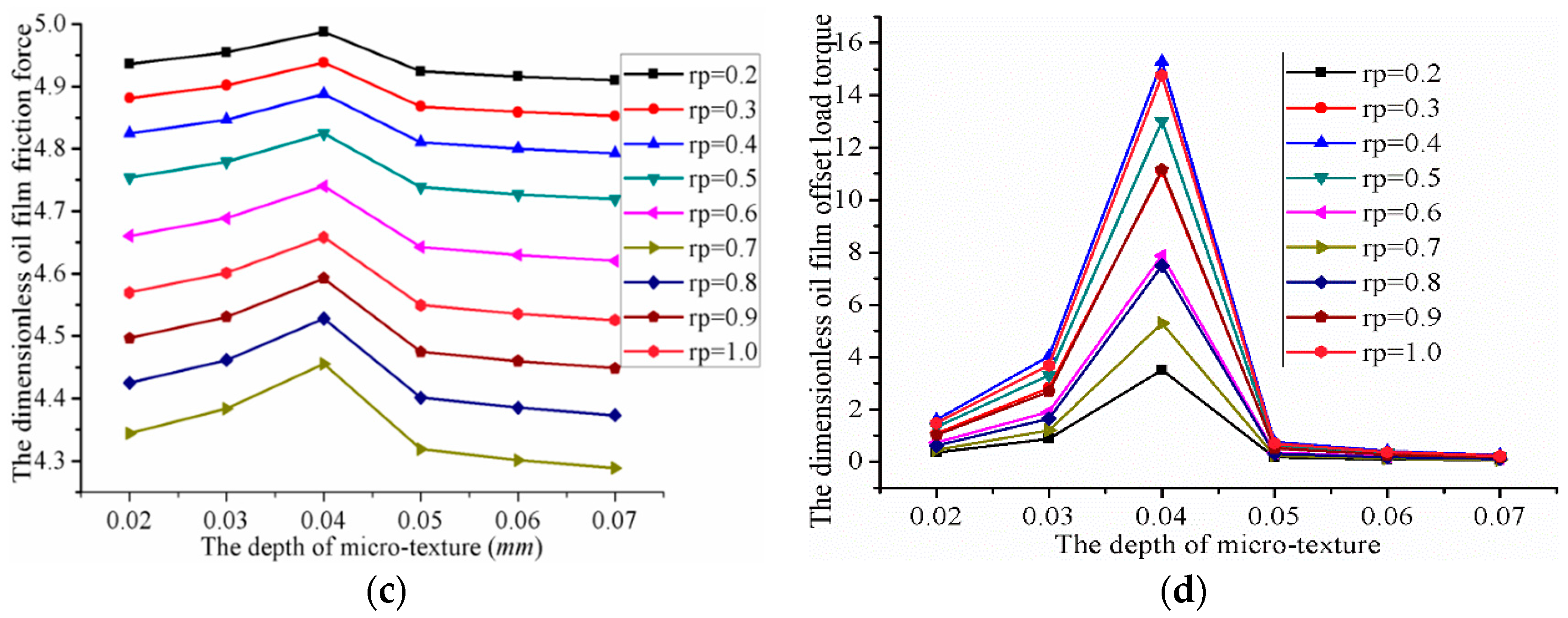
- The oil film friction force was 4.9876 (maximum) when the half-side length was 0.2 mm, and 4.2649 (minimum) when the half-side length was 0.7 mm and the depth was 0.07 mm. The maximum value was thus 0.7227 more than the minimum.
- The oil film offset load torque was 0.0596 (minimum) when the half-side length is 0.2 mm, and 15.273 (maximum) when the half-side length was 0.4 mm and the depth was 0.04 mm. The maximum value was thus 15.2134 higher than the minimum.
6. The Influence of Microtexture’s Depth on the Performance of the Valve Plate
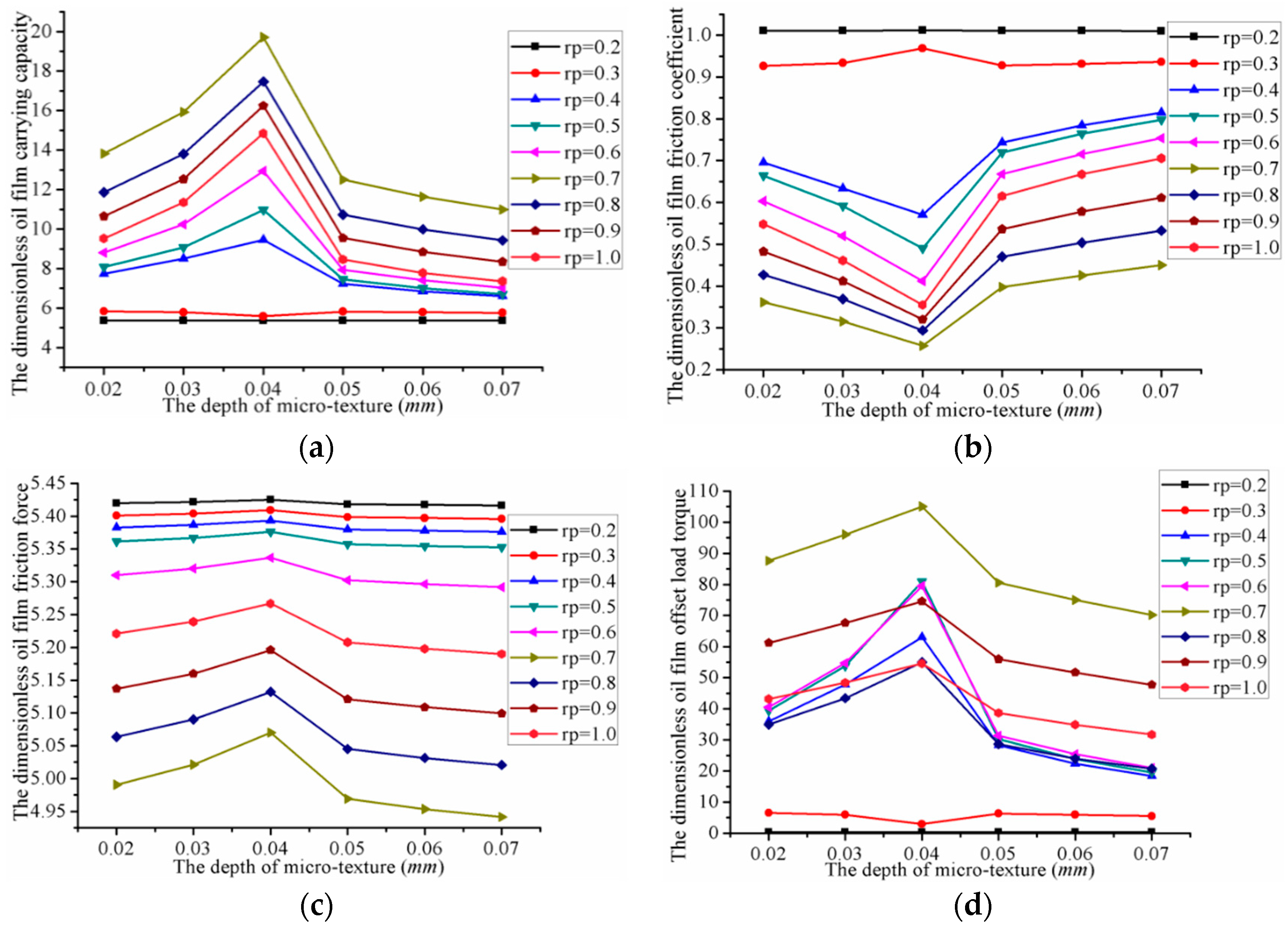
6.1. The Influence of the Micro-Hemispherical Texture Depth on the Performance of Valve Plate
- The oil film carrying capacity, friction force and offset load torque reached a maximum when the depth was 0.04 mm. The oil film friction coefficient reached its minimum at this point.
- The oil film carrying capacity, friction force and offset load torque reached their minimum when the depth was 0.07 mm. The oil film friction coefficient reached its maximum at this point.
6.2. The Influence of Micro-Cylindrical Texture Depth on the Performance of a Valve Plate
- When the depth of the micro-cylindrical texture was 0.04 mm, the oil film carrying capacity, friction force, and offset load torque reached their maximum values, while the oil film friction coefficient reached its minimum value.
- When the depth of the micro-cylindrical texture was 0.07 mm, the oil film carrying capacity, friction force, and offset load torque reached their minimum, while the oil film friction coefficient reached its maximum.
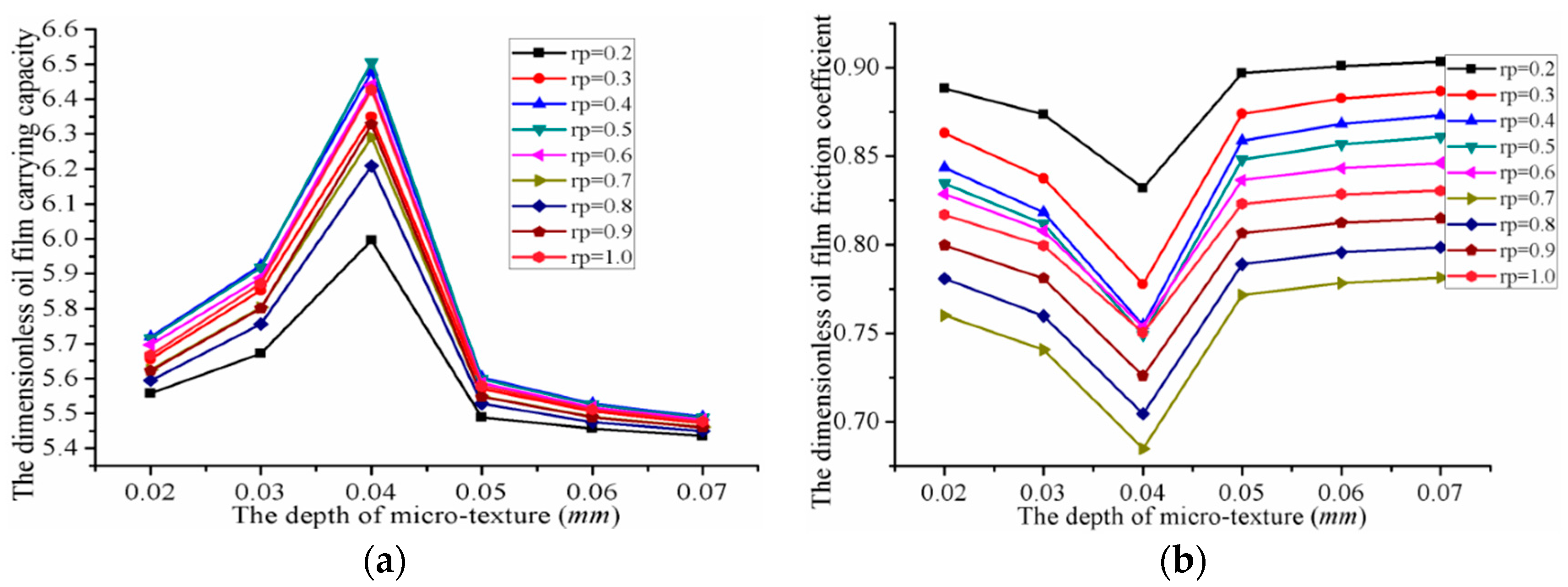
6.3. The Influence of Micro-Square Texture Depth on the Performance of a Valve Plate
- When the depth of the micro-square texture was 0.04 mm, the oil film carrying capacity, friction force, and offset load torque reaches their maximum values, while the friction coefficient reached its minimum.
- When the depth of the micro-cylindrical texture was 0.07 mm, the oil film carrying capacity, friction force, and offset load torque reached their minimum values, while the friction coefficient reached its maximum.
7. Comparison of the Optimum Oil Film Pressure Lubrication Characteristics
- (1)
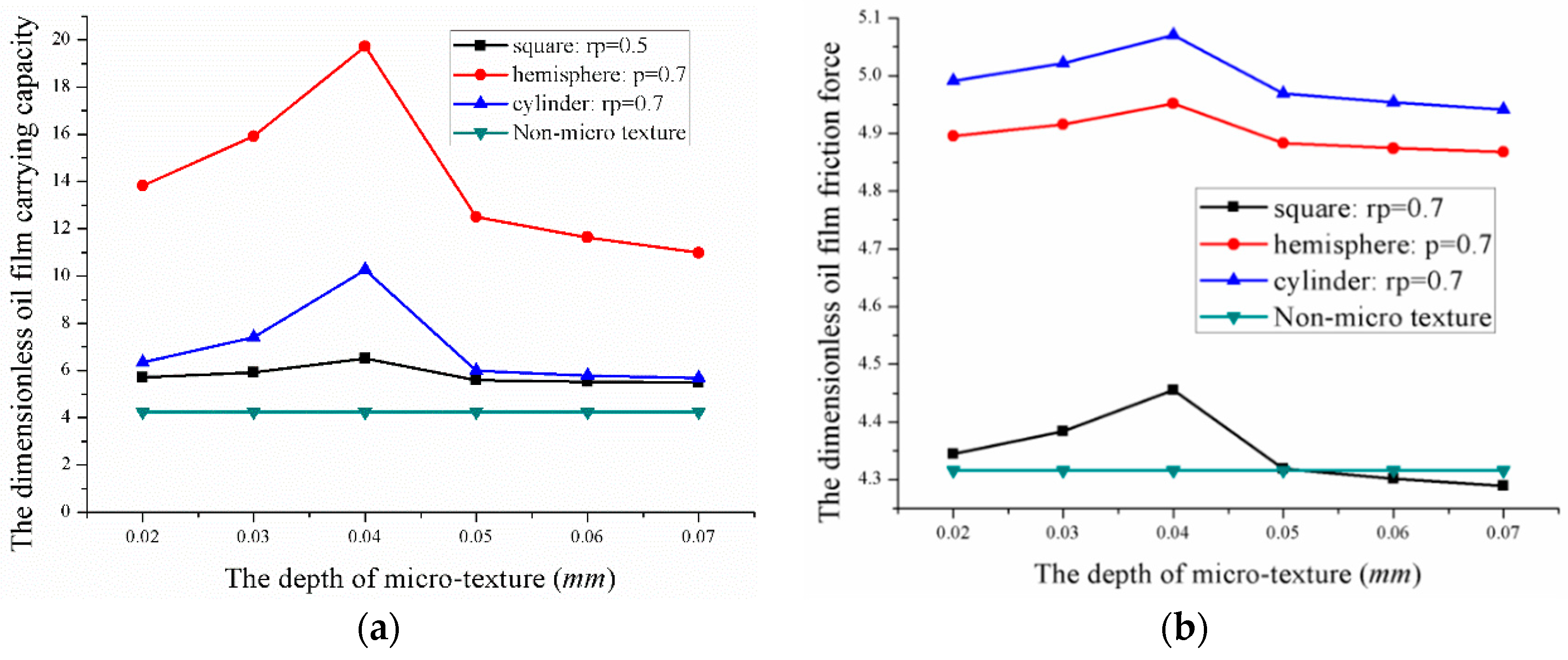
- The dimensionless oil film carrying capacity was 19.71, 10.27 and 6.5, when the radius (half-side length) was 0.7 mm and the depth 0.04 mm for the micro-hemispherical texture, micro-cylindrical texture, and micro-square texture. At this point, the dimensionless friction coefficient reached its minimum.
- (2)
- The dimensionless oil film friction coefficient was 0.2571, 0.4821 and 0.6848 when the radius (half-side length) was 0.7 mm and the depth was 0.04 mm for the micro-hemispherical texture, micro-cylindrical texture, and micro-square texture respectively. At this point, the friction coefficient reached a minimum.
8. Conclusions
- The oil film pressure of the valve plate pair increased at the convergence region anticlockwise. A smaller oil film thickness leads to greater oil film pressure, thus resulting in a greater load bearing capacity. Until the balance with the extrusion force, the cylinder is no longer tilted, the cylinder and the valve plate are completely separated by the lubricant, and a full fluid lubrication is theoretically formed. The presence of a microtexture increases the lubricant film thickness and decreases the friction force.
- The oil film pressure lubrication characteristics of the valve plate pair is affected by the type of microtexture. Microtexture can effectively reduce the friction coefficient and improve the carrying capacity, which can significantly reduce the power loss and improve the efficiency of the valve plate pair.
- A hydrodynamic effect is produced by the convergence gap formed between the surface texture micro-pit of the valve plate and the surface of the cylinder block. The final hydrodynamic effect of the lubrication oil film is affected by the shape and size of the convergence gap.
- The lubrication characteristics of the valve plate are influenced by the different microtexture parameters and can be improved by optimizing the microtexture parameters. We were able to determine the optimal parameter combinations for three types of shapes. The degree of improvement in the dimensionless oil film pressure lubrication characteristics from highest to lowest was as follows: micro-hemispherical texture > micro-cylindrical texture > micro-square texture.
Author Contributions
Funding
Acknowledgments
Conflicts of Interest
References
- Fang, Y.; Shirakashi, M. Mixed Lubrication Characteristics between the Piston and Cylinder in Hydraulic Piston Pump-Motor. Psychiatry Res. 1995, 117, 658–666. [Google Scholar] [CrossRef]
- Ahn, S.Y.; Rhim, Y.C.; Hong, Y.S. Lubrication and dynamic characteristics of a cylinder block in an axial piston pump. Am. Soc. Mech. Eng. 2005, 223–224. [Google Scholar]
- Costa, H.L.; Hutchings, I.M. Hydrodynamic lubrication of textured steel surfaces under reciprocating sliding conditions. Tribol. Int. 2007, 40, 1227–1238. [Google Scholar] [CrossRef]
- Greiner, C.; Merz, T.; Braun, D.; Codrignani, A.; Magagnato, F. Optimum dimple diameter for friction reduction with laser surface texturing: The effect of velocity gradient. Surf. Topogr. 2015, 3, 044001. [Google Scholar] [CrossRef]
- Vrbka, M.; Šamánek, O.; Šperka, P.; Navrat, T.; Křupka, I.; Hartl, M. Effect of surface texturing on rolling contact fatigue within mixed lubricated non-conformal rolling/sliding contacts. Meccanica 2011, 46, 491–498. [Google Scholar] [CrossRef]
- Tang, W.; Zhou, Y.; Zhu, H. The effect of surface texturing on reducing the friction and wear of steel under lubricated sliding contact. Appl. Surf. Sci. 2013, 273, 199–204. [Google Scholar] [CrossRef]
- Sung, I.H.; Lee, H.S.; Kim, D.E. Effect of surface topography on the frictional behavior at the micro/nano-scale. Wear 2003, 254, 1019–1031. [Google Scholar] [CrossRef]
- Qiu, Y.; Khonsari, M.M. Experimental investigation of tribological performance of laser textured stainless steel rings. Tribol. Int. 2011, 44, 635–644. [Google Scholar] [CrossRef]
- Ronen, A.; Etsion, I.; Kligerman, Y. Friction-Reducing Surface-Texturing in Reciprocating Automotive Components. Tribol. Trans. 2001, 44, 359–366. [Google Scholar] [CrossRef]
- Lu, P.; Wood, R.; Gee, M. The Friction Reducing Effect of Square-Shaped Surface Textures under Lubricated Line-Contacts—An Experimental Study. Lubricants 2016, 4, 26. [Google Scholar] [CrossRef]
- Wang, X.; Adachi, K.; Otsuka, K. Optimization of the surface texture for silicon carbide sliding in water. Appl. Surf. Sci. 2006, 253, 1282–1286. [Google Scholar] [CrossRef]
- Antoszewski, B. Mechanical Seals with Sliding Surface Texture—Model Fluid Flow and Some Aspects of the Laser Forming of the Texture. Procedia Eng. 2012, 39, 51–62. [Google Scholar] [CrossRef]
- Etsion, I. Improving Tribological Performance of Mechanical Components by Laser Surface Texturing. Tribol. Lett. 2004, 17, 733–737. [Google Scholar] [CrossRef]
- Gels, S.; Murrenhoff, H. Simulation of the Lubricating Film between Contoured Piston and Cylinder. Int. J. Fluid Power 2010, 11, 15–24. [Google Scholar] [CrossRef]
- Scaraggi, M.; Mezzapesa, F.P.; Carbone, G. Minimize friction of lubricated laser-microtextured-surfaces by tuning microholes depth. Tribol. Int. 2014, 75, 123–127. [Google Scholar] [CrossRef]
- Wang, X.; Kato, K.; Adachi, K.; Aizawa, K. Loads carrying capacity map for the surface texture design of SiC thrust bearing sliding in water. Tribol. Int. 2003, 36, 189–197. [Google Scholar] [CrossRef]
- Gualtieri, E.; Borghi, A.; Calabri, L. Increasing nanohardness and reducing friction of nitride steel by laser surface texturing. Tribol. Int. 2009, 42, 699–705. [Google Scholar] [CrossRef]
- Gachot, C.; Rosenkranz, A.; Hsu, S.M.; Costa, H.L. A critical assessment of surface texturing for friction and wear improvement. Wear 2017, 372, 21–41. [Google Scholar] [CrossRef]
- Gropper, D.; Wang, L.; Harvey, T.J. Hydrodynamic lubrication of textured surfaces: A review of modeling techniques and key findings. Tribol. Int. 2016, 94, 509–529. [Google Scholar] [CrossRef]
- Pettersson, U.; Jacobson, S. Influence of surface texture on boundary lubricated sliding contacts. Tribol. Int. 2003, 36, 857–864. [Google Scholar] [CrossRef]
- Pettersson, U.; Jacobson, S. Friction and Wear Properties of Micro Textured DLC Coated Surfaces in Boundary Lubricated Sliding. Tribol. Lett. 2004, 17, 553–559. [Google Scholar] [CrossRef]
- Etsion, I. Improving Tribological Performance of Mechanical Sealsby Laser Surface Texturing. In Proceedings of the 17th International Pump Users Symposium, Houston, TX, USA, 6–9 March 2000; Volume 17, pp. 17–22. [Google Scholar]
- Etsion, I. State of the Art in Laser Surface Texturing. J. Tribol. 2005, 127, 761–762. [Google Scholar] [CrossRef]
- Ryk, G.; Etsion, I. Testing piston rings with partial laser surface texturing for friction reduction. Wear 2006, 261, 792–796. [Google Scholar] [CrossRef]
- Kovalchenko, A.; Ajayi, O.; Erdemir, A.; Etsion, I. The effect of laser surface texturing on transitions in lubrication regimes during unidirectional sliding contact. Tribol. Int. 2005, 38, 219–225. [Google Scholar] [CrossRef]
- Chen, Z.; Goltsberg, R.; Etsion, I. A universal model for a frictionless elastic-plastic coated spherical normal contact with moderate to large coating thicknesses. Tribol. Int. 2017, 114, 485–493. [Google Scholar] [CrossRef]
- Goltsberg, R.; Etsion, I. Contact area and maximum equivalent stress in elastic spherical contact with thin hard coating. Tribol. Int. 2016, 93, 289–296. [Google Scholar] [CrossRef]
- Baker, J.; Ivantysynova, M. Investigation of Power Losses in the Lubricating Gap between Cylinder Block and Valve Plate of Axial Piston Machines. In Proceedings of the Fluid Power Net International PHD Symposium, Cracow, Poland, 1–5 July 2008. [Google Scholar]
- Ivantysynova, M.; Baker, J. Power Loss in the Lubricating Gap between Cylinder Block and Valve Plate of Swash Plate Type Axial Piston Machines. Int. J. Fluid Power 2009, 10, 29–43. [Google Scholar] [CrossRef]
- Shin, J.H.; Kim, K.W. Effect of surface non-flatness on the lubrication characteristics in the valve part of a swash-plate type axial piston pump. Meccanica 2014, 49, 1275–1295. [Google Scholar] [CrossRef]
- Rosenkranz, A.; Reinert, L.; Gachot, C.; Mücklich, F. Alignment and wear debris effects between laser-patterned steel surfaces under dry sliding conditions. Wear 2014, 318, 49–61. [Google Scholar] [CrossRef]
- Tala-Ighil, N.; Fillon, M.; Maspeyrot, P. Effect of textured area on the performances of a hydrodynamic journal bearing. Tribol. Int. 2011, 44, 211–219. [Google Scholar] [CrossRef]
- Marchetto, D.; Rota, A.; Calabri, L. AFM investigation of tribological properties of nano-patterned silicon surface. Wear 2008, 265, 577–582. [Google Scholar] [CrossRef]
- Epstein, D.; Keer, L.; Janewang, Q. Effect of Surface Topography on Contact Fatigue in Mixed Lubrication. Tribol. Trans. 2003, 46, 506–513. [Google Scholar] [CrossRef]
- Shen, C.; Huang, W.; Ma, G. A novel surface texture for magnetic fluid lubrication. Surf. Coat. Technol. 2009, 204, 433–439. [Google Scholar] [CrossRef]


| Symbol | Name | Symbol | Name |
|---|---|---|---|
| hp | Depth of the microtexture (0.15 × 10⁻³ m) | rp | Radius of the microtexture (0.1 × 10⁻³ m) |
| h0 | Initial oil film thickness (0.0325 × 10⁻³ m) | a | Side length of micro-square texture (0.2 × 10⁻³ m) |
| r1 | Inner diameter of interior sealing belt (0.0298 m) | μ | Viscosity of lubricating oil (0.05 Pa·s) |
| r2 | Outside diameter of interior sealing belt (m) | θ | Circumferential angle at a point (°) |
| r3 | Inner diameter of outer sealing belt (m) | ϕ | Cylinder block tilt angle (0.0004 °) |
| r4 | Outside diameter of outer sealing belt (0.0419 m) | ω | Cylinder block speed (3000 rpm) |
| h | Oil film thickness (m) | P | Oil film pressure (Pa) |
| Name | Radial Number | Circumferential Number | Radius/Half Side Length | Pressure |
|---|---|---|---|---|
| Number | 6 | 26 | 0.1 mm | 101,325 Pa |
| Parameter | Radius/mm | Depth/mm | Minimum | Radius/mm | Depth/mm | Maximum | Δ(Max − Min) |
|---|---|---|---|---|---|---|---|
| Carrying capacity | 0.2 | 0.02–0.07 | 5.36 | 0.7 | 0.04 | 19.72 | 14.36 |
| Friction coefficient | 0.7 | 0.04 | 0.2571 | 0.2 | 0.02–0.07 | 1.0117 | 0.7546 |
| Friction force | 0.7 | 0.07 | 5.0701 | 0.2 | 0.02–0.07 | 5.4252 | 0.3551 |
| Offset load torque | 0.2 | 0.02–0.07 | 0.001433 | 0.7 | 0.04 | 110.41 | 110.4086 |
| Parameter | Radius/mm | Depth/mm | Minimum | Radius/mm | Depth/mm | Maximum | Δ(Max − Min) |
|---|---|---|---|---|---|---|---|
| Carrying capacity | 0.2 | 0.02–0.07 | 5.36 | 0.7 | 0.04 | 10.37 | 5.01 |
| Friction coefficient | 0.7 | 0.04 | 0.4821 | 0.2 | 0.02–0.07 | 1.0106 | 0.5285 |
| Friction force | 0.7 | 0.06 | 4.9517 | 0.2 | 0.02–0.07 | 5.4193 | 0.4676 |
| Offset load torque | 0.2 | 0.02–0.07 | 0.001436 | 0.7 | 0.04 | 110.4086 | 45.7466 |
| Parameter | Radius/mm | Depth/mm | Minimum | Radius/mm | Depth/mm | Maximum | Δ(Max − Min) |
|---|---|---|---|---|---|---|---|
| Carrying capacity | 0.2 | 0.07 | 5.43 | 0.5 | 0.04 | 6.50 | 1.07 |
| Friction Coefficient | 0.7 | 0.04 | 0.6848 | 0.2 | 0.07 | 0.9069 | 0.2221 |
| Friction force | 0.7 | 0.07 | 4.2649 | 0.2 | 0.04 | 4.9876 | 0.7227 |
| Offset load torque | 0.2 | 0.07 | 0.0596 | 0.4 | 0.04 | 15.273 | 15.2134 |
| Microtexture | Radius/mm | Depth/mm | Carrying Capacity | Friction Coefficient |
|---|---|---|---|---|
| Hemispherical | 0.7 | 0.04 | 19.71 | 0.2571 |
| Cylindrical | 0.7 | 0.04 | 10.27 | 0.4821 |
| Square | 0.7 | 0.04 | 6.5 | 0.6848 |
© 2018 by the authors. Licensee MDPI, Basel, Switzerland. This article is an open access article distributed under the terms and conditions of the Creative Commons Attribution (CC BY) license (http://creativecommons.org/licenses/by/4.0/).
Share and Cite
Wang, Z.; Hu, S.; Zhang, H.; Ji, H.; Yang, J.; Liang, W. Effect of Surface Texturing Parameters on the Lubrication Characteristics of an Axial Piston Pump Valve Plate. Lubricants 2018, 6, 49. https://doi.org/10.3390/lubricants6020049
Wang Z, Hu S, Zhang H, Ji H, Yang J, Liang W. Effect of Surface Texturing Parameters on the Lubrication Characteristics of an Axial Piston Pump Valve Plate. Lubricants. 2018; 6(2):49. https://doi.org/10.3390/lubricants6020049
Chicago/Turabian StyleWang, Zhaoqiang, Shan Hu, Hengyun Zhang, Hong Ji, Jian Yang, and Wei Liang. 2018. "Effect of Surface Texturing Parameters on the Lubrication Characteristics of an Axial Piston Pump Valve Plate" Lubricants 6, no. 2: 49. https://doi.org/10.3390/lubricants6020049
APA StyleWang, Z., Hu, S., Zhang, H., Ji, H., Yang, J., & Liang, W. (2018). Effect of Surface Texturing Parameters on the Lubrication Characteristics of an Axial Piston Pump Valve Plate. Lubricants, 6(2), 49. https://doi.org/10.3390/lubricants6020049