Abstract
In this article, a geometrical model of different microtextures is established for an axial piston pump valve plate. A finite differential method was used to solve the Reynolds equation for the oil film thickness and pressure, which were simulated under different microtextures. The influence of microtexture shape and structure on performance was studied and optimal parameters sought. Different convergence gaps are formed by different microtexture radii, and they produce different hydrodynamic effects. The lubrication characteristics of the valve plate are better when a microtexture is used and are influenced by the type of microtexture. We reached the following conclusions: (1) The lubrication characteristics of the valve plate are influenced by different microtexture parameters and can be improved by optimizing the microtexture parameters; (2) There is an optimal parameter combination when adding microtexture with three shapes (spherical, cylindrical and square) and the optimal dimensionless oil film pressure lubrication characteristics can be obtained; (3) The degree of improvement in the dimensionless oil film pressure lubrication characteristics was (listed from highest to lowest): micro-hemispherical texture > micro-cylindrical texture > micro-square texture.
1. Introduction
The valve plate is an important component of an axial piston pump, which is a widely used hydraulic power component. Modern hydraulic transmission technology generally aims to achieve improvements at high-speed and high-pressure, with strict conditions on the working performance and service life of the valve plate. Numerical analysis has previously been carried out in order to express the mixed lubrication characteristics between the valve plate and cylinder block in the swash-plate type piston pump and motor [1,2].
Surface texturing is the design of a specific shape, size, and arrangement of the surface of a friction pair by means of physical and chemical methods. The surface texturing acts as a micro fluid hydrodynamic lubrication bearing under different conditions, enhances the hydrodynamic effect and improves the bearing capacity [3,4]. The lubricant reservoir provides continuous lubrication, and captures the wear particles to reduce the furrows [5]. Surface texturing is a widely used approach to improve the load capacity, wear resistance, and friction coefficient of tribological mechanical components [6,7,8], including sliding surfaces [9,10]. Surface texture can also improve the running-in process, to smooth contact surfaces, resulting in low friction [11,12]. A significant improvement in performance can also be obtained by creating a regular micro-surface structure in the form of micro-dimples [13,14]. Compared with plane surfaces, dimples will help to lower the coefficient of friction between surfaces [15]. The optimal geometric and distributive ranges of the micro-pits are known, and the load-carrying capacity can be increased compared to untextured surfaces [16,17].
Surface texturing to control friction and wear has been the focus of numerous studies in the last few decades [18]. Understanding the influence of surface properties on the performance of hydrodynamically lubricated contacts has been the aim of numerous studies [19]. Surface microtexturing of the valve plate is a new topic. In 2003, Pettersson studied the friction and wear behavior of boundary-lubricated sliding surfaces and found that they are influenced by the surface texture. Lubricant can be supplied even inside the contact by small reservoirs, resulting in a reduced friction and a prolonged lifetime where there is tribological contact [20]. In 2004, Pettersson again investigated the friction and wear properties of boundary-lubricated textured surfaces and found that the well-defined surface textures of square depressions or parallel grooves of different widths and distributions can be produced by lithography and anisotropic etching of silicon wafers [21]. In 2000, Etsion presented that the tribological performance of mechanical can be improved seals by laser surface texturing [22,23]. In 2006, Etsion presented an experimental study to evaluate the effect of partial laser surface texturing (LST) on friction reduction in piston rings and found that the partial LST piston rings exhibited about one quarter of lower friction [24]. The beneficial effects of laser surface texturing are more pronounced at higher speeds and loads and with higher viscosity oil [25]. In 2016, Etsion used the finite element analysis to investigate the elastic contact of a sphere with a thin hard coating compressed by a rigid flat and also introduced a new approach for calculating the limit of elasticity in the coated system [26,27]. In 2008, Ivantysynova proposed that a surface micro-wave texture can be added to the design of the axial piston pump in order to increase the load-carrying properties of port plate pairs. The wave-like microtexture can generate an additional hydrodynamic effect and reduce the power loss of the piston pump and motor [28]. In 2009, a mathematical model of the wave-like microtexture was established and solved. It demonstrated that a wave-like micro-surface shape variation applied to the valve plate gap surface reduces power loss in the cylinder block–valve plate interface. The effect of the waved surface is most significant at low operating pressures. The power loss in the cylinder block–valve plate interface could be reduced when using the waved surface, compared to the standard cylinder block–valve plate interface design [29]. In 2014, Shin investigated the effect of surface non-flatness on the lubrication characteristics of the bearing/sealing parts between the cylinder barrel and valve plate in a hydrostatic axial piston pump. They found that the circumferentially wavy surface would allow for better performance of motion stability and power efficiency than a radially wedged land surface [30].
A large part of the lubricant on the surface of the non-texture specimen is thrown out due to the fast operation speed of the friction pair, and the generated abrasive particles will aggravate the wear of the surface. The surface microtexture can store lubricating oil. The lubricating oil stored in the texture will overflow when the surface is partially worn out, and will be replenished to a certain extent, which can provide continuous lubrication to the friction pair. The surface texture can also play the role of containing the wear debris [31], thereby improving the wear caused by the abrasive particles. Common texture patterns include columns, pits, grooves, and the like. The presence of a local cavity (texture) increases the lubricant film thickness and decreases the friction force. Partial texturing can generate a hydrodynamic lift when the texture is located in the declining part of the contact pressure field [32]. The convergence gap formed between the edge of the microtexture and the surface of the friction pair can produce a hydrodynamic effect along the direction of the lubricant velocity under hydrodynamic lubrication conditions [33].
Formerly, research has mainly focused on the effects of single shape microtexture parameters, such as the depth, diameter, and area ratio, on the lubrication characteristics of the motor. Part of the literature has examined the different shapes of the micro-dimple surface texture [34,35]. This paper focuses on the research of the surface texture field and optimize the parameters of microtexture. Three different microtexture shapes and parameters were selected to study their effects on lubrication characteristics. A finite differential method was used to solve the Reynolds equation for the oil film thickness and pressure, which were simulated under different microtextures. The influence of microtexture shape and structure on performance was studied and optimal parameters sought. It was found that the processing of a certain regular texture on the surface of the friction pair can improve the friction characteristics and lubrication effect between the friction pairs, in which the shape of the texture geometrical parameters is one of the key factors, and only in the appropriate range will have excellent lubrication effect; otherwise, it is counterproductive. There is an optimal parameter combination when adding microtexture with three shapes and the optimal dimensionless oil film pressure lubrication characteristics can be obtained.
2. Establishment and Solution of Microtexture of Valve Plate
Tribological properties can be optimized by adjusting the shape and parameters of the surface texture. The microtexture model of different types and parameters (including spherical, cylindrical, and square) was established based on the mathematical model of the valve plate under hydrodynamic lubrication conditions.
2.1. Micro-Hemispherical Texture Oil Film Morphological Equation Modeling of Valve Plate
Figure 1 shows the geometry of a micro-hemispherical texture element relative to the surface of the valve plate. The cylinder block is located in the upper part of the graph, while the micro-hemispherical texture is located in the lower part of the graph. Figure 1a is the front view of the mathematical model for the micro-hemispherical texture’s depth, while Figure 1b is the top view of the mathematical model. We defined hp as a distance from the bottom center of micro-hemispherical to the surface of valve plate, rp is the radius of the micro-hemispherical texture, while r is the distance from point A on the micro-hemispherical to its center.
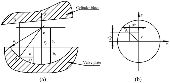
Figure 1.
Mathematical model of micro-hemispherical texture form: (a) The front view of the mathematical model; and (b) The top view of the mathematical model.
The distance from the micro-hemispherical center to the surface of valve plate can be expressed as follows:
where y1, R and r are defined in Figure 1. The sum of the distance from the micro-hemispherical texture center to the surface of the valve plate and the depth of the micro-hemispherical texture is equal to the radius of micro-hemispherical texture, which can be written as:
where:
The distance from the point A of the micro-hemispherical texture to the bottom of the microtexture is:
where r is the distance from point A to micro-hemispherical texture’s center, which can be calculated as:
where dx and dy are the local coordinates of the micro-hemispherical texture. The distance from point A to the surface of the microtexture is:
When Equations (1)–(5) are incorporated into Equation (6), we can obtain:
We defined θ as circumferential angle at a point, ϕ is the cylinder block tilt angle. Therefore, the oil film thickness equation formed by the micro-hemispherical texture and the tilted cylinder block is:
2.2. Micro-Cylindrical Texture Oil Film Morphological Equation Modeling for Valve Plate
Figure 2 shows the geometry of a micro-cylindrical texture element relative to the surface of valve plate. We defined hp as a distance from the bottom center of micro-cylinder to the surface of valve plate, h0 is the initial oil film thickness, while r is the distance from point A on the micro-cylindrical texture to its center. This can be calculated as follows:
where dx and dy are the local coordinates of the micro-cylindrical texture. Therefore, the oil film thickness equation formed by the micro-cylindrical texture and the tilted cylinder block is:
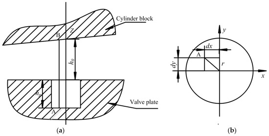
Figure 2.
Mathematical model of micro-cylindrical texture form: (a) The front view of the mathematical model; and (b) The top view of the mathematical model.
2.3. Micro-Square Texture Oil Film Morphological Equation Modeling for Valve Plate
Figure 3 shows the geometry of a micro-square texture element relative to the surface of valve plate. In this figure, hp is the distance from the bottom center of micro-square to the surface of valve plate, a is the side length of micro-square, and dx and dy are the local coordinates of the micro-square. Therefore, the oil film thickness equation formed by a micro-square and a tilted cylinder block is:
where:
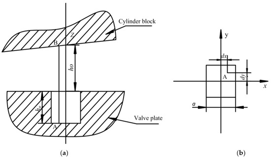
Figure 3.
Mathematical model of micro-square texture form: (a) The front view of the mathematical model; and (b) The top view of the mathematical model.
The structure parameters of the microtexture are listed in Table 1.

Table 1.
Lubrication characteristic parameters of the microtexture.
2.4. Solution of the Microtexture Model for Valve Plate
Figure 4 shows the flow chart for calculating the oil film thickness and pressure of valve plate with microtexture. When solving for the oil film thickness and pressure of a microtexture element on a valve plate, we must first determine the parameters of the valve plate and microtexture, then divide the valve plate’s model into meshes. We solved the Reynolds equation using the finite difference method, after setting boundary conditions. Two cases should be considered when calculating the oil film thickness of microtextures: one is when the mesh point is in the microtexture; the other case is when the mesh point is not in the microtexture.
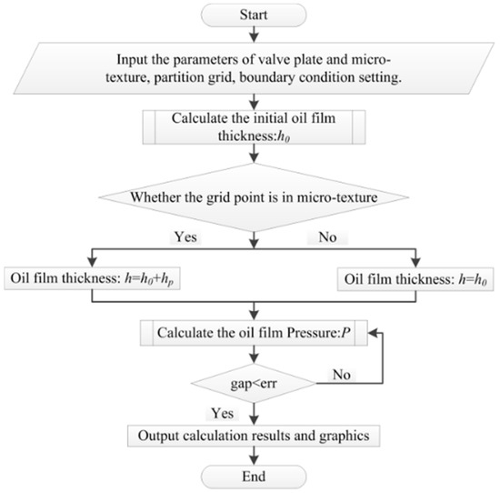
Figure 4.
Flow chart for calculating the oil film thickness and pressure of valve plate with microtexture.
3. Oil Film Thickness and Pressure Distribution of a Valve Plate without Microtexture
Figure 5 and Figure 6 show the distributions of the oil film thickness and pressure. We show a three-dimensional and two-dimensional result. The figures were generated using (Fortran Algorithm Description, John Backus, New York, NY, USA) and (Matlab Plotting Software Description, MathWorks, Natick, MA, USA).
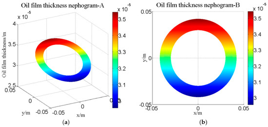
Figure 5.
Oil film thickness distribution of the valve plate: (a) Three-dimensional distribution diagram; and (b) Two-dimensional distribution diagram.

Figure 6.
Oil film pressure distribution of the valve plate: (a) Three-dimensional graph of pressure distribution; and (b) Two-dimensional pressure distribution diagram.
3.1. Solution of Oil Film Pressure of a Valve Plate without Microtexture
Two-dimensional polar coordinates Reynolds equation as follows.
The oil film in the contact area was ring-shaped. Converting the rectangular coordinate system into polar coordinate system, the following is obtained.
The two-dimensional polar coordinates-based Reynolds equation can be simplified as follows:
Discretization along the X and Y directions was undertaken using the following:
Discretization:
where: E = A + B + C + D,
3.2. Distribution of Oil Film Thickness across the Valve Plate
Figure 5 shows the distribution of the oil film thickness for the valve plate by theoretical calculation and simulation. Figure 5a is a three-dimensional diagram of the thickness distribution. Figure 5b is a two-dimensional diagram of the wedge oil film thickness.
The thickness of the wedge-shaped oil film varies with the inclination of the cylinder block. The oil is thicker at the top and thinner at the bottom, while there is no oil film in the center.
3.3. Distribution of Oil Film Pressure across the Valve Plate
Figure 6 shows the oil film pressure distribution across a valve plate. Figure 6a is a three-dimensional representation of the oil film pressure distribution. Figure 6b is the two-dimensional oil film pressure distribution diagram.
Local high pressure is generated in the gap convergence region along the rotating direction of cylinder (counterclockwise), thus making the distribution of oil film pressure non-linear in the sealing belt. This creates an offset load torque and causes a dynamic change in the wedge-shaped oil film. In this figure, the oil film pressure increases in the second quadrant where the hydrodynamic effects are obvious, while the oil film thickness is larger in the low pressure zone.
4. Oil Film Thickness and Pressure Distribution of a Microtextured Valve Plate
The number of microtextures on the surface of the valve plate are shown in Table 2. The pressure in the high- and low-pressure zone was set to 101,325 Pa, while the external pressure was set to 101,325 Pa.

Table 2.
Structure parameters of the microtexture.
4.1. Oil Film Thickness and Pressure Distribution of Valve Plate with Micro-Hemispherical Texture
Figure 7 shows the oil film thickness distribution of the valve plate with micro-hemispherical texture. Figure 7a is the three-dimensional distribution graph of the oil film thickness, Figure 7b is the two-dimensional distribution graph and Figure 7c is a local magnification graph of 7a.

Figure 7.
Oil film thickness distribution of a valve plate with micro-hemispherical texture: (a) The three-dimensional graph; (b) The two-dimensional graph; and (c) The three-dimensional locally magnified.
Figure 8 shows the oil film pressure distribution of a valve plate with micro-hemispherical texture. The local high pressure was produced by machining the micro-hemispherical texture. Figure 8a is the three-dimensional distribution graph, Figure 8b is the two-dimensional distribution graph and Figure 8c is a locally magnified view of 8a. The micro-hemispherical texture was arranged on the surface of the valve plate.

Figure 8.
Oil film pressure distribution of a valve plate with micro-hemispherical texture: (a) Three-dimensional distribution graph; (b) Two-dimensional distribution graph; and (c) A locally magnified view.
4.2. Oil Film Thickness and Pressure Distribution of a Valve Plate with Micro-Cylindrical Texture
Figure 9 shows the oil film thickness distribution of a valve plate with micro-cylindrical texture. Figure 9a is the three-dimensional distribution graph; Figure 9b is the two-dimensional distribution graph; and Figure 9c is the local magnification graph.

Figure 9.
Oil film thickness distribution of the valve plate with micro-cylindrical texture: (a) Three-dimensional distribution graph; (b) Two-dimensional distribution graph; and (c) A locally magnified view.
Figure 10 shows the distribution of oil film pressure for the valve plate with micro-cylindrical texturing. Figure 10a is the three-dimensional distribution graph; Figure 10b is the two-dimensional distribution graph; and Figure 10c is a locally magnified view of Figure 10a.

Figure 10.
Oil film pressure distribution of the valve plate with micro-cylindrical texture. (a) Three-dimensional distribution graph; (b) Two-dimensional distribution graph; and (c) A locally magnified view.
4.3. Oil Film Thickness and Pressure Distribution of a Valve Plate with a Micro-Square Texture
Figure 11 shows the oil film thickness distribution of a valve plate with a micro-square texture. Figure 11a is the three-dimensional distribution graph; Figure 11b is the two-dimensional distribution graph; and Figure 11c is a locally magnified view. The micro-square texture was arranged regularly along the radial and circumferential directions in the Top Dead Center (TDC) and Bottom Dead Center (BDC) of the valve plate.

Figure 11.
Oil film thickness distribution of a valve plate with a micro-square texture: (a) Three-dimensional distribution graph; (b) Two-dimensional distribution graph; and (c) A locally magnified view.
Figure 12 shows the oil film pressure distribution of a valve plate with a micro-square texture. Figure 12a is the three-dimensional distribution graph; Figure 12b is the two-dimensional distribution graph; and Figure 12c is a locally magnified view.

Figure 12.
Oil film pressure distribution of a valve plate with a micro-square texture: (a) Three-dimensional distribution graph; (b) Two-dimensional distribution graph; and (c) A locally magnified view.
4.4. Comparison of the Oil Film Pressure Lubrication Characteristics of Different Microtexture
Figure 7, Figure 8, Figure 9, Figure 10, Figure 11 and Figure 12 show the distributions of pressure and oil film thickness for three types of microtextures: hemispherical, cylindrical, and square. For each parameter and shape, we show a three-dimensional and two-dimensional result, and there is also a locally magnified image. The figures were generated using (Fortran Algorithm Description) and (Matlab Plotting Software Description).
With a hemispherical microtexture. The oil film thickness increased locally as the hydraulic oil was entered and stored inside the micro-hemispherical texture region. The oil film thickness changed due to the internal depth variation of the microtexture. The micro-hemispherical texture is arranged regularly along the radial and circumferential directions in the BDC and TDC of the valve plate. There are changes in oil film thickness and gaps when the hydraulic oil flowed into and out of the micro-hemispherical texture region. Positive pressure was generated when the hydraulic oil flowed along the region of convergence formed by the hemispherical structure, resulting in elevation of the local oil film pressure in the hemispherical regions. It is not straightforward to generate positive or negative pressure when the hydraulic oil flows along a region of divergence and thus, it is difficult to generate hydrodynamic effects.
With a cylindrical microtexture. The oil film thickness increased locally as the hydraulic oil entered and was stored inside the micro-cylindrical textured region. The internal depth of the micro-cylindrical texture did not change, unlike for the micro-hemispherical texture. The oil film region had locally high pressure after machining of the micro-cylindrical texture. Furthermore, the oil film pressure formed by the micro-cylindrical texture was higher near the outer sealing belt of the valve plate.
Finally, with a square microtexture. The oil film thickness increased locally as the hydraulic oil entered and was stored inside the micro-square texture region. The internal depth of the micro-square texture did not change, unlike for the micro-hemispherical texture. The oil film region produced local high pressure, which was similar to that of the micro-hemispherical texture. The oil film pressure formed by the micro-square texture was higher in the TDC of the microtexture, while the oil film pressure was lower in the BDC of the microtexture. It was different from the influence of the micro-hemispherical texture and micro-cylindrical texture on the pressure of valve plate.
5. The Influence of Microtexture Radius on the Performance of the Valve Plate
Different microtexture shapes and parameters were selected for the simulation study in order to optimize the oil film carrying capacity, friction coefficient, friction force, and the offset load torque. The microtexture shapes selected were spherical, cylindrical, and square. The radius (half side length) of the micro-hemispherical texture, micro-cylindrical texture and micro-square texture varies from 0.2 to 1.0 mm, while the depth of microtexture varies from 0.02 to 0.07 mm.
5.1. The Influence of Micro-Hemispherical Texture Radius on the Performance of the Valve Plate
Figure 13 shows the influence of the micro-hemispherical texture’s radius on the performance of the valve plate. Table 3 shows the oil film lubrication characteristic parameter value of micro-hemispherical texture. The radius of micro-hemispherical texture varies from 0.2 to 1.0 mm. Δ(Max − Min) represents the value of maximum minus minimum. There was no change for the dimensionless oil film pressure lubrication characteristics when the radius was 0.2 mm. This indicated that the micro-hemispherical texture had little or no effect on the valve plate. The oil film pressure lubrication characteristics varied differently when depth was kept constant and the radius was increased. This indicated that the oil film pressure lubrication characteristics are affected by the micro-hemispherical radius.
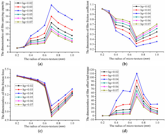
Figure 13.
Influence of micro-hemispherical radius on the performance of the valve plate: (a) The carrying capacity; (b) The friction coefficient; (c) The friction force; and (d) The offset load torque.

Table 3.
The oil film lubrication characteristic parameter value of micro-hemispherical texture.
- The oil film carrying capacity was 5.36 (minimum) when the radius was 0.2 mm, while the oil film carrying capacity was 19.72 (maximum) when the radius was 0.7 mm and the depth was 0.04 mm. Thus, the value could be increased by 14.36 compared to the minimum carrying capacity.
- The oil film friction coefficient was 1.0117 (maximum) when the radius was 0.2 mm, while the oil film friction coefficient was 0.2571 (minimum) when the radius was 0.7 mm and the depth was 0.04 mm. The value thus increased by 0.7546 compared to the minimum oil film friction coefficient.
- The oil film friction force was 5.4252 (maximum) when the radius was 0.2 mm, and 5.0701 (manimum) when the radius was 0.7 mm and the depth was 0.07 mm. The value thus increased by 0.3551 compared to the minimum oil film friction coefficient.
- The oil film offset load torque was 0.001433 (minimum) when the radius of micro-hemispherical texture was 0.2 mm, and 110.41 (maximum) when the radius was 0.7 mm and the depth was 0.04 mm. The optimal value thus increased by 110.4086 compared with the minimum oil film offset load torque.
A different convergence gap was formed by different microtexture radius, which produced different hydrodynamic effects. The hydrodynamic effects of the micro-hemispherical texture increased with an increase in radius, within a certain range, however beyond that the hydrodynamic effects decreased due to the interactions within the texture. The optimal oil film lubrication characteristics can thus be obtained by optimizing the micro-hemispherical texture radius.
5.2. The Influence of Micro-Cylindrical Texture’s Radius on the Performance of Valve Plate
Figure 14 shows the influence of the micro-cylindrical texture’s radius on the performance of valve plate. Table 4 shows the oil film lubrication characteristic parameter value of micro-cylindrical texture. The radius of the micro-cylindrical texture ranged from 0.2 to 1.0 mm. Δ(Max − Min) represents the value of maximum minus minimum.
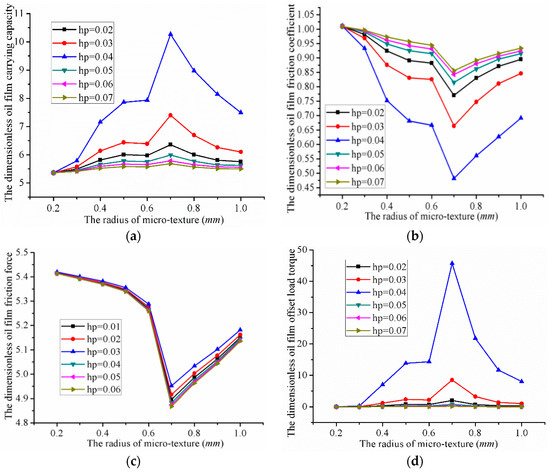
Figure 14.
Influence of the micro-cylindrical texture radius on the performance of valve plate: (a) The carrying capacity; (b) the friction coefficient; (c) The friction force; and (d) The offset load torque.

Table 4.
The oil film lubrication characteristic parameter value of micro-cylindrical texture.
- The oil film carrying capacity was 5.36 (minimum) when the radius was 0.2 mm, and 10.37 (maximum) when the radius was 0.7 mm and the depth was 0.04 mm. Thus, the value could be increased by 5.01 compared with the minimum oil carrying capacity.
- The oil film friction coefficient is 1.0106 (maximum) when the radius was 0.2 mm, and 0.4821 (minimum) when the radius was 0.7 mm and the depth was 0.04 mm. The value thus increased by 0.5285 compared with the minimum friction coefficient.
- The oil film friction force was 5.4193 (maximum) when the radius was 0.2 mm, and 4.9517 (minimum) when the radius was 0.7 mm and the depth was 0.06 mm. The value could thus be increased by 0.4676 compared with the minimum friction force.
- The oil film offset load torque reached a minimum of 0.001436 when the radius was 0.2 mm, and a maximum of 45.748 when the radius was 0.7 mm and the depth was 0.04 mm. The maximum value was thus 45.7466 greater than the minimum.
5.3. The Influence of Micro-Square Texture’s Half Side Length on the Performance of Valve Plate
Figure 15 shows the influence of the micro-square texture’s radius on the performance of the valve plate. Table 5 shows the oil film lubrication characteristic parameter value of micro-square texture. The half side length of the micro-square texture was varied from 0.2 to 1.0 mm. Δ(Max − Min) represents the value of maximum minus minimum.
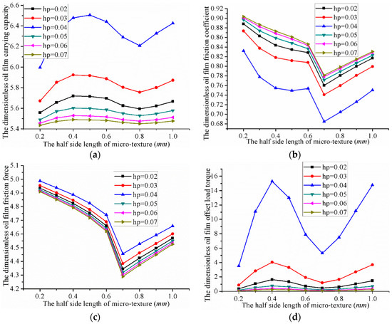
Figure 15.
Influence of micro-square texture’s radius on the performance of the valve plate: (a) The carrying capacity; (b) The friction coefficient; (c) The friction force; and (d) The offset load torque.

Table 5.
The oil film lubrication characteristic parameter value of micro-square texture.
- The oil film carrying capacity was 5.43 (minimum) when the half-side length is 0.2 mm, and 6.50 (maximum) when the half-side length was 0.5 mm and the depth was 0.04 mm. The maximum value was thus 1.07 higher than the minimum carrying capacity.
- The oil film friction coefficient was 0.9069 (maximum) when the half-side length is 0.2 mm, and 0.6848 (minimum) when the half-side length was 0.7 mm and the depth was 0.04 mm. The value could thus be increased by 0.2221 compared to the minimum.
- The oil film friction force was 4.9876 (maximum) when the half-side length was 0.2 mm, and 4.2649 (minimum) when the half-side length was 0.7 mm and the depth was 0.07 mm. The maximum value was thus 0.7227 more than the minimum.
- The oil film offset load torque was 0.0596 (minimum) when the half-side length is 0.2 mm, and 15.273 (maximum) when the half-side length was 0.4 mm and the depth was 0.04 mm. The maximum value was thus 15.2134 higher than the minimum.
6. The Influence of Microtexture’s Depth on the Performance of the Valve Plate
6.1. The Influence of the Micro-Hemispherical Texture Depth on the Performance of Valve Plate
Figure 16 shows the influence of the micro-hemispherical texture’s depth on valve plate performance. The depth of micro-hemispherical texture varied from 0.02 to 0.07 mm. As we can see from the graph, the oil film pressure lubrication characteristics varied differently with an increase in micro-hemispherical depth at the same radius. This indicated that the oil film pressure lubrication characteristics are affected by the micro-hemispherical texture’s depth. A different convergence gap is formed by different microtexture depths, which produced different hydrodynamic effects. The hydrodynamic effects of micro-hemispherical textures increased with an increase in depth, although beyond a certain range it decreased due to the initial oil film thickness. The optimal oil film lubrication characteristics could be obtained by the optimal micro-hemispherical texture depth.
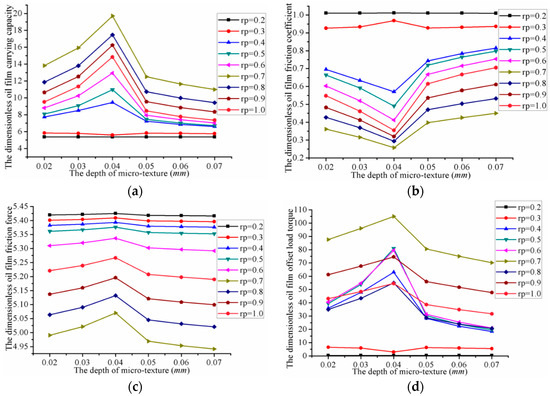
Figure 16.
Influence of micro-hemispherical texture’s depth on the performance of the valve plate: (a) The carrying capacity; (b) The friction coefficient; (c) The friction force; and (d) The offset load torque.
- The oil film carrying capacity, friction force and offset load torque reached a maximum when the depth was 0.04 mm. The oil film friction coefficient reached its minimum at this point.
- The oil film carrying capacity, friction force and offset load torque reached their minimum when the depth was 0.07 mm. The oil film friction coefficient reached its maximum at this point.
6.2. The Influence of Micro-Cylindrical Texture Depth on the Performance of a Valve Plate
Figure 17 shows the influence of the micro-cylindrical texture depth on the performance of the valve plate. The depth varied from 0.02 to 0.07 mm. As we can see from the graph:
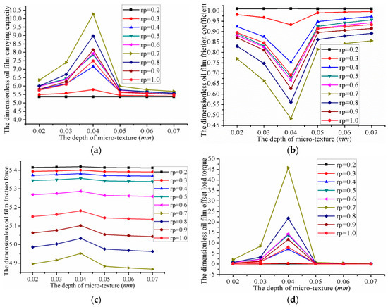
Figure 17.
Influence of micro-cylindrical texture depth on the performance of the valve plate: (a) The carrying capacity; (b) The friction coefficient; (c) The friction force; and (d) The offset load torque.
- When the depth of the micro-cylindrical texture was 0.04 mm, the oil film carrying capacity, friction force, and offset load torque reached their maximum values, while the oil film friction coefficient reached its minimum value.
- When the depth of the micro-cylindrical texture was 0.07 mm, the oil film carrying capacity, friction force, and offset load torque reached their minimum, while the oil film friction coefficient reached its maximum.
6.3. The Influence of Micro-Square Texture Depth on the Performance of a Valve Plate
Figure 18 shows the influence of the micro-square texture depth on the lubrication characteristics of a valve plate. The depth of the micro-cylindrical texture varied from 0.02 to 0.07 mm. As we can see from the graph:
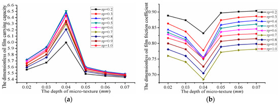

Figure 18.
Influence of micro-square texture’s depth on the performance of the valve plate: (a) The carrying capacity; (b) The friction coefficient; (c) The friction force; and (d) The offset load torque.
- When the depth of the micro-square texture was 0.04 mm, the oil film carrying capacity, friction force, and offset load torque reaches their maximum values, while the friction coefficient reached its minimum.
- When the depth of the micro-cylindrical texture was 0.07 mm, the oil film carrying capacity, friction force, and offset load torque reached their minimum values, while the friction coefficient reached its maximum.
7. Comparison of the Optimum Oil Film Pressure Lubrication Characteristics
The oil film lubrication characteristics of valve plates under pressure are better when a microtexture is used, compared to no microtexture. The study of tribological performance for three types of microtexture surface found that:
For a fixed microtexture radius, an increase in depth tends to lead to an initial increase then decrease in the dimensionless oil film carrying capacity, friction force, and offset load torque. The oil film friction coefficient has the tendency to decrease first and then increase. Furthermore, at a fixed microtexture depth, an increase in the microtexture radius or side length leads to the dimensionless oil film carrying capacity, friction force, and offset load torque first increasing first then decreasing. The oil film friction coefficient tends to decrease first and then to increase. This indicated that the optimal oil film lubrication characteristics could be obtained by optimizing micro-hemispherical texture depth.
Figure 19 shows the oil film pressure lubrication characteristic curves at the optimal parameters. Table 6 shows the optimal oil film lubrication characteristic values.
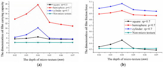
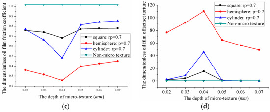
Figure 19.
Influence of microtexture’s types on the optimum oil film pressure lubrication characteristics: (a) The carrying capacity; (b) The friction coefficient; (c) The friction force; and (d) The offset load torque.

Table 6.
Optimal oil film pressure lubrication characteristic values.
- (1)
- The dimensionless oil film carrying capacity was 19.71, 10.27 and 6.5, when the radius (half-side length) was 0.7 mm and the depth 0.04 mm for the micro-hemispherical texture, micro-cylindrical texture, and micro-square texture. At this point, the dimensionless friction coefficient reached its minimum.
- (2)
- The dimensionless oil film friction coefficient was 0.2571, 0.4821 and 0.6848 when the radius (half-side length) was 0.7 mm and the depth was 0.04 mm for the micro-hemispherical texture, micro-cylindrical texture, and micro-square texture respectively. At this point, the friction coefficient reached a minimum.
8. Conclusions
In order to explore the influence of microtexture on the oil film pressure lubrication characteristics, we carried out the analyses described above. A valve plate with surface microtextures of different types and parameters, including hemispherical, cylindrical, and square, was modeled and compared to that with no microtexture. The oil film thickness and the pressure of the valve plate under different microtextures were derived and solved. The influence of the microtexture type on the oil film lubrication characteristics was analyzed. The simulation results showed that:
- The oil film pressure of the valve plate pair increased at the convergence region anticlockwise. A smaller oil film thickness leads to greater oil film pressure, thus resulting in a greater load bearing capacity. Until the balance with the extrusion force, the cylinder is no longer tilted, the cylinder and the valve plate are completely separated by the lubricant, and a full fluid lubrication is theoretically formed. The presence of a microtexture increases the lubricant film thickness and decreases the friction force.
- The oil film pressure lubrication characteristics of the valve plate pair is affected by the type of microtexture. Microtexture can effectively reduce the friction coefficient and improve the carrying capacity, which can significantly reduce the power loss and improve the efficiency of the valve plate pair.
- A hydrodynamic effect is produced by the convergence gap formed between the surface texture micro-pit of the valve plate and the surface of the cylinder block. The final hydrodynamic effect of the lubrication oil film is affected by the shape and size of the convergence gap.
- The lubrication characteristics of the valve plate are influenced by the different microtexture parameters and can be improved by optimizing the microtexture parameters. We were able to determine the optimal parameter combinations for three types of shapes. The degree of improvement in the dimensionless oil film pressure lubrication characteristics from highest to lowest was as follows: micro-hemispherical texture > micro-cylindrical texture > micro-square texture.
Author Contributions
Z.W. and S.H. conceived and designed the research; S.H. performed the research; H.Z. and W.L. analyzed the data; H.J. and J.Y. contributed reagents/materials/analysis tools; Shan Hu wrote the paper.
Funding
This research was funded by the Project (No. 51505272 and No. 51505274) and supported by the National Natural Science Foundation of China and the Project (No. GZKF-201514) supported by the Open Foundation of the State Key Laboratory of Fluid Power and Mechatronic Systems.
Acknowledgments
Thanks are due to Editors for valuable opinion, we are also grateful for all the reviewer’s comments.
Conflicts of Interest
The authors declare no conflict of interest.
References
- Fang, Y.; Shirakashi, M. Mixed Lubrication Characteristics between the Piston and Cylinder in Hydraulic Piston Pump-Motor. Psychiatry Res. 1995, 117, 658–666. [Google Scholar] [CrossRef]
- Ahn, S.Y.; Rhim, Y.C.; Hong, Y.S. Lubrication and dynamic characteristics of a cylinder block in an axial piston pump. Am. Soc. Mech. Eng. 2005, 223–224. [Google Scholar]
- Costa, H.L.; Hutchings, I.M. Hydrodynamic lubrication of textured steel surfaces under reciprocating sliding conditions. Tribol. Int. 2007, 40, 1227–1238. [Google Scholar] [CrossRef]
- Greiner, C.; Merz, T.; Braun, D.; Codrignani, A.; Magagnato, F. Optimum dimple diameter for friction reduction with laser surface texturing: The effect of velocity gradient. Surf. Topogr. 2015, 3, 044001. [Google Scholar] [CrossRef]
- Vrbka, M.; Šamánek, O.; Šperka, P.; Navrat, T.; Křupka, I.; Hartl, M. Effect of surface texturing on rolling contact fatigue within mixed lubricated non-conformal rolling/sliding contacts. Meccanica 2011, 46, 491–498. [Google Scholar] [CrossRef]
- Tang, W.; Zhou, Y.; Zhu, H. The effect of surface texturing on reducing the friction and wear of steel under lubricated sliding contact. Appl. Surf. Sci. 2013, 273, 199–204. [Google Scholar] [CrossRef]
- Sung, I.H.; Lee, H.S.; Kim, D.E. Effect of surface topography on the frictional behavior at the micro/nano-scale. Wear 2003, 254, 1019–1031. [Google Scholar] [CrossRef]
- Qiu, Y.; Khonsari, M.M. Experimental investigation of tribological performance of laser textured stainless steel rings. Tribol. Int. 2011, 44, 635–644. [Google Scholar] [CrossRef]
- Ronen, A.; Etsion, I.; Kligerman, Y. Friction-Reducing Surface-Texturing in Reciprocating Automotive Components. Tribol. Trans. 2001, 44, 359–366. [Google Scholar] [CrossRef]
- Lu, P.; Wood, R.; Gee, M. The Friction Reducing Effect of Square-Shaped Surface Textures under Lubricated Line-Contacts—An Experimental Study. Lubricants 2016, 4, 26. [Google Scholar] [CrossRef]
- Wang, X.; Adachi, K.; Otsuka, K. Optimization of the surface texture for silicon carbide sliding in water. Appl. Surf. Sci. 2006, 253, 1282–1286. [Google Scholar] [CrossRef]
- Antoszewski, B. Mechanical Seals with Sliding Surface Texture—Model Fluid Flow and Some Aspects of the Laser Forming of the Texture. Procedia Eng. 2012, 39, 51–62. [Google Scholar] [CrossRef]
- Etsion, I. Improving Tribological Performance of Mechanical Components by Laser Surface Texturing. Tribol. Lett. 2004, 17, 733–737. [Google Scholar] [CrossRef]
- Gels, S.; Murrenhoff, H. Simulation of the Lubricating Film between Contoured Piston and Cylinder. Int. J. Fluid Power 2010, 11, 15–24. [Google Scholar] [CrossRef]
- Scaraggi, M.; Mezzapesa, F.P.; Carbone, G. Minimize friction of lubricated laser-microtextured-surfaces by tuning microholes depth. Tribol. Int. 2014, 75, 123–127. [Google Scholar] [CrossRef]
- Wang, X.; Kato, K.; Adachi, K.; Aizawa, K. Loads carrying capacity map for the surface texture design of SiC thrust bearing sliding in water. Tribol. Int. 2003, 36, 189–197. [Google Scholar] [CrossRef]
- Gualtieri, E.; Borghi, A.; Calabri, L. Increasing nanohardness and reducing friction of nitride steel by laser surface texturing. Tribol. Int. 2009, 42, 699–705. [Google Scholar] [CrossRef]
- Gachot, C.; Rosenkranz, A.; Hsu, S.M.; Costa, H.L. A critical assessment of surface texturing for friction and wear improvement. Wear 2017, 372, 21–41. [Google Scholar] [CrossRef]
- Gropper, D.; Wang, L.; Harvey, T.J. Hydrodynamic lubrication of textured surfaces: A review of modeling techniques and key findings. Tribol. Int. 2016, 94, 509–529. [Google Scholar] [CrossRef]
- Pettersson, U.; Jacobson, S. Influence of surface texture on boundary lubricated sliding contacts. Tribol. Int. 2003, 36, 857–864. [Google Scholar] [CrossRef]
- Pettersson, U.; Jacobson, S. Friction and Wear Properties of Micro Textured DLC Coated Surfaces in Boundary Lubricated Sliding. Tribol. Lett. 2004, 17, 553–559. [Google Scholar] [CrossRef]
- Etsion, I. Improving Tribological Performance of Mechanical Sealsby Laser Surface Texturing. In Proceedings of the 17th International Pump Users Symposium, Houston, TX, USA, 6–9 March 2000; Volume 17, pp. 17–22. [Google Scholar]
- Etsion, I. State of the Art in Laser Surface Texturing. J. Tribol. 2005, 127, 761–762. [Google Scholar] [CrossRef]
- Ryk, G.; Etsion, I. Testing piston rings with partial laser surface texturing for friction reduction. Wear 2006, 261, 792–796. [Google Scholar] [CrossRef]
- Kovalchenko, A.; Ajayi, O.; Erdemir, A.; Etsion, I. The effect of laser surface texturing on transitions in lubrication regimes during unidirectional sliding contact. Tribol. Int. 2005, 38, 219–225. [Google Scholar] [CrossRef]
- Chen, Z.; Goltsberg, R.; Etsion, I. A universal model for a frictionless elastic-plastic coated spherical normal contact with moderate to large coating thicknesses. Tribol. Int. 2017, 114, 485–493. [Google Scholar] [CrossRef]
- Goltsberg, R.; Etsion, I. Contact area and maximum equivalent stress in elastic spherical contact with thin hard coating. Tribol. Int. 2016, 93, 289–296. [Google Scholar] [CrossRef]
- Baker, J.; Ivantysynova, M. Investigation of Power Losses in the Lubricating Gap between Cylinder Block and Valve Plate of Axial Piston Machines. In Proceedings of the Fluid Power Net International PHD Symposium, Cracow, Poland, 1–5 July 2008. [Google Scholar]
- Ivantysynova, M.; Baker, J. Power Loss in the Lubricating Gap between Cylinder Block and Valve Plate of Swash Plate Type Axial Piston Machines. Int. J. Fluid Power 2009, 10, 29–43. [Google Scholar] [CrossRef]
- Shin, J.H.; Kim, K.W. Effect of surface non-flatness on the lubrication characteristics in the valve part of a swash-plate type axial piston pump. Meccanica 2014, 49, 1275–1295. [Google Scholar] [CrossRef]
- Rosenkranz, A.; Reinert, L.; Gachot, C.; Mücklich, F. Alignment and wear debris effects between laser-patterned steel surfaces under dry sliding conditions. Wear 2014, 318, 49–61. [Google Scholar] [CrossRef]
- Tala-Ighil, N.; Fillon, M.; Maspeyrot, P. Effect of textured area on the performances of a hydrodynamic journal bearing. Tribol. Int. 2011, 44, 211–219. [Google Scholar] [CrossRef]
- Marchetto, D.; Rota, A.; Calabri, L. AFM investigation of tribological properties of nano-patterned silicon surface. Wear 2008, 265, 577–582. [Google Scholar] [CrossRef]
- Epstein, D.; Keer, L.; Janewang, Q. Effect of Surface Topography on Contact Fatigue in Mixed Lubrication. Tribol. Trans. 2003, 46, 506–513. [Google Scholar] [CrossRef]
- Shen, C.; Huang, W.; Ma, G. A novel surface texture for magnetic fluid lubrication. Surf. Coat. Technol. 2009, 204, 433–439. [Google Scholar] [CrossRef]
© 2018 by the authors. Licensee MDPI, Basel, Switzerland. This article is an open access article distributed under the terms and conditions of the Creative Commons Attribution (CC BY) license (http://creativecommons.org/licenses/by/4.0/).