1. Introduction
Growing fuel costs and increasing environmental legislation limits lead to the development of even more efficient internal combustion engines (ICE). Engines for use in heavy-duty trucks do have to deal with special requirements for efficiency because of rigorous consumer demands for commercial services and tightening of limiting values for polluting emissions due to legislative control. Examining the global energy consumption by transportation vehicles heavy-duty vehicles are ranking on the second place behind light-duty vehicles (including passenger cars, vans, pick-ups, sports utility vehicles) even before aviation, buses, marine and rail vehicles. Considering heavy-duty vehicles, 26% of the fuel energy is needed to overcome the parasitical frictional losses [
1]. Beside drivetrain and auxiliary electrification, friction reduction is an effective method to increase fuel economy and decrease the pollution of greenhouse gases.
In combustion engines, the journal bearings of the cranktrain constitute the second largest source of frictional losses beside the piston assembly. Therefore, the reduction of the frictional losses for these key sources is one significant goal of future low friction engines by using e.g. low friction coatings, new surface treatment technologies and low viscous lubricants. While a very large part of literature focuses on the friction power losses of biggest contributor of friction in the engine, the piston assembly, only very little literature exists that tries to address the friction power losses of the journal bearings under realistic operating conditions. The published works usually obtain their results from tear down/strip down tests, which are conceptually not able to impose realistic loads onto the journal bearings, or from journal bearing test-rigs [
2,
3]. From a theoretical viewpoint, many different analytical and numerical methods to investigate journal bearings are available. However, the accuracy of these methods is not clear as there has not been an attempt to the knowledge of the authors to directly compare simulation and experiment systematically for a large range of different speeds, dynamic loads and lubricant classes. Only recently a simulation method was published [
4,
5,
6] which was shown to be able to calculate the friction power losses of journal bearings under realistic working conditions with very high dynamic loads highly accurately.
In combination with a large set of measurements for different speeds and loads for a heavy-duty Diesel engine this simulation method is going to be used in the following to investigate the friction power losses for this engine in great detail. Besides quantifying the losses, a comparison to works from literature and an investigation of the friction reduction potential of the highly loaded journal bearings using ultra-low viscosity lubricants [
7,
8,
9] is also presented.
2. Experimental Setup
The required experimental data for the simulation are obtained from a friction dynamometer developed by the authors [
10,
11]. The engine under test is a heavy-duty Diesel engine of the 13 litre-class.
During the experimental investigations the engine is basically motored, but to generate realistic engine loads the engine is charged with externally pressurised air. By using the external air charging system peak cylinder pressures comparable to fired engine operation can be realized in a very flexible manner ranging from low part load to full load operation [
10,
11]. As there is no combustion present, this has some influence in particular on the friction of the piston assembly. However, for the journal bearings this represents fired engine operation very closely [
10]. The engine load, more precisely, the cylinder pressure is measured in all 6 cylinders using piezoelectric pressure sensors.
For the measurements on the pressurised dynamometer all engine auxiliary systems (except the oil pump), such as water pump, fuel pump, fuel injection system, alternator, viscofan, air pressure pump where removed to ensure that only the basic engine system is tested during the measurements. The oil temperature and pressure is measured directly in the oil gallery at the position of the original engine oil pressure sensor. To allow external temperature control, the oil pan of the test engine was modified; the oil supply temperature was controlled externally with an accuracy of about C.
It is the aim of this work to investigate the friction power losses under realistic operating conditions as they are present under real world driving. To achieve this, only the coolant temperature was externally stabilized to 90
C. The oil temperature for every operating condition was taken from measurements obtained from a fired engine, where the oil supply temperature increased significantly (up to 120
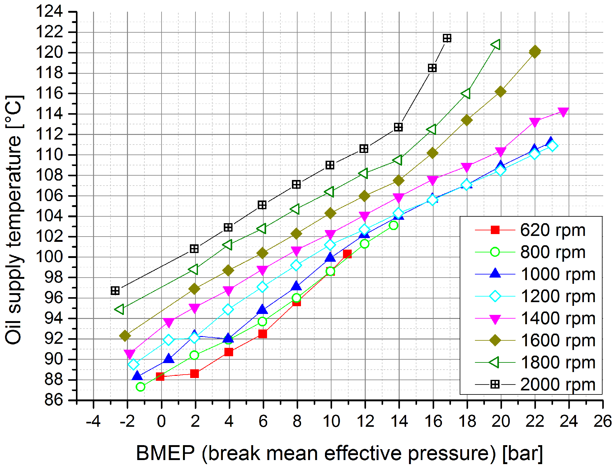
C) depending on the actual engine load. The exact oil supply temperatures are shown in
Figure 1.
Figure 1.
Oil supply temperatures measured at the oil gallery for fired operation (see text).
Figure 1.
Oil supply temperatures measured at the oil gallery for fired operation (see text).
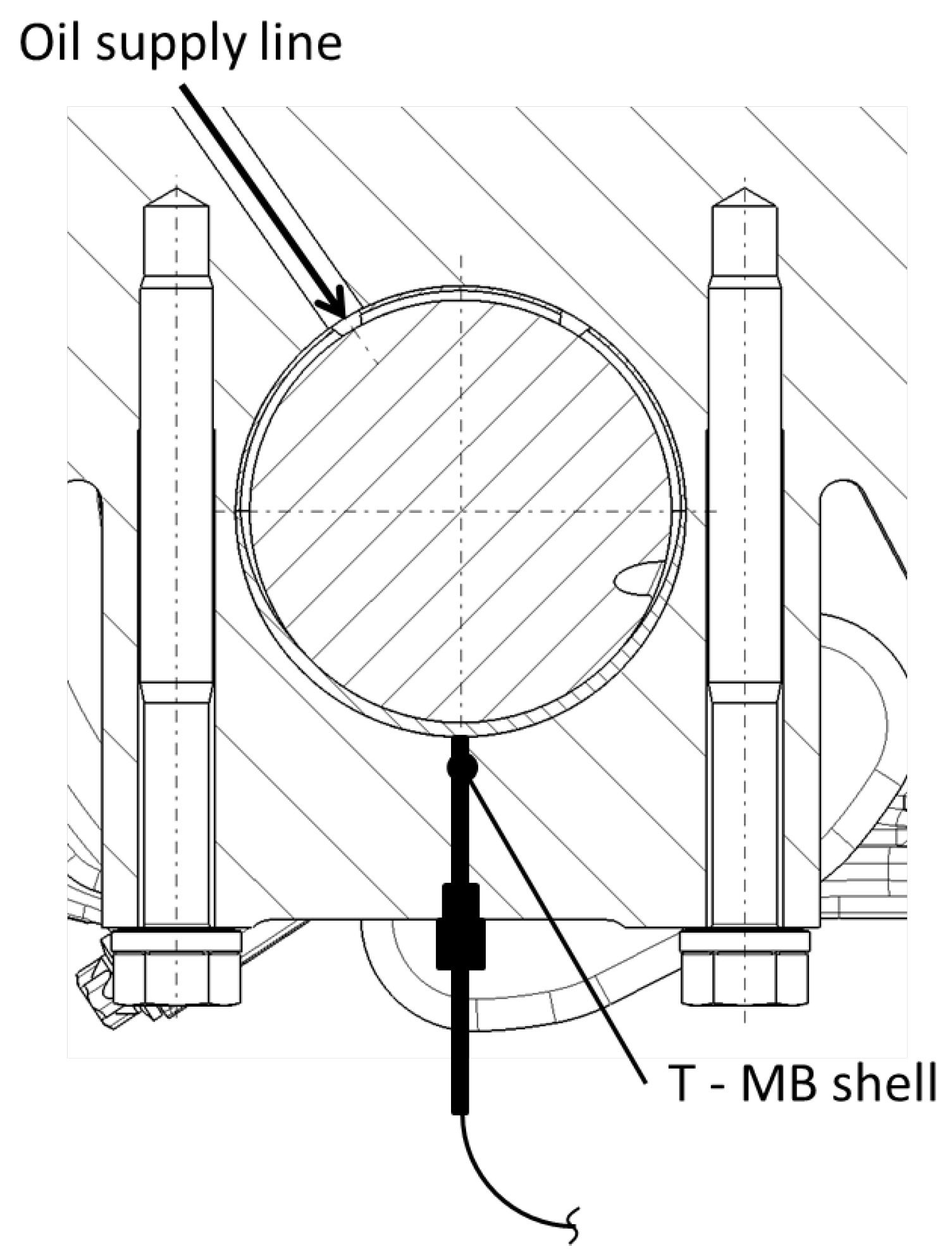
For every operating condition, the bearing shell temperatures of main bearing 2 and 3 were measured using thermocouple sensors of type K at the main bearing shell which have an accuracy of
C. This was realized by a mechanical modification of the main bearing bracket as shown in
Figure 2.
Figure 2.
Temperature measuring point at main bearing shell.
Figure 2.
Temperature measuring point at main bearing shell.
The lubricant used for the measurements is a fully synthetic ACEA E6/E7 Castrol Enduron Low SAPS 5W30 oil, which provides a high temperature high shear rate (HTHS) viscosity of 3.6 mPa s (see also
Table 1).
Table 1.
Rheological properties of the lubricants.
Table 1.
Rheological properties of the lubricants.
| | 0W20 | Castrol 5W30 |
|---|
| Density at 15 C | 842 kg/m | 853 kg/m |
| Dynamic viscosity at 40 C | 37.9 mPa s | 59.6 mPa s |
| Dynamic viscosity at 100 C | 7.2 mPa s | 10.1 mPa s |
| HTHS-viscosity | 3.6/2.8 mPa s | 3.6 mPa s |
3. Determining the Friction Loss of the Journal Bearings
In previous works a simulation methodology was realised with AVL EXCITE Power Unit (AVL EXCITE Power Unit Version 2011.2, AVL List GmbH, Advanced Simulation Technology, Hans-List-Platz 1, 8020 Graz Austria,
www.avl.com.), that is capable to calculate the friction losses in journal bearings accurately as could be shown in direct comparison to experimental data [
4,
6]. Basically, the used simulation approach comprises an elastic multi-body simulation and describes the lubricant film isothermally using Reynolds’ equation together with the Greenwood and Tripp approach to describe the metal-metal contact. Many important aspects of the method have been discussed in detail in previous works, so only a short summary is reproduced here for brevity: in particular the role of the piezoviscous effect and the Non-Newtonian behaviour of the lubricant and their consideration in the method [
6,
12], the thermal processes in the journal bearing and the developed equivalent bearing temperature relation that describes them suitably [
6,
13]. The method was put to test in direct comparison to experimental data in two different works [
4,
6] for different speeds, loads and lubricant classes. For a rather complete overview we refer to [
5] (The book chapter can be downloaded for free at
http://www.intechopen.com/).
For the calculation of the friction power losses in the journal bearings an engine model was setup within an elastic multi-body dynamics solver (AVL EXCITE Power Unit Version 2011.2, AVL List GmbH, Advanced Simulation Technology, Hans-List-Platz 1, 8020 Graz Austria, www.avl.com) using this method. The simulation consists of finite element structures of crankshaft, main bearing and conrod, where all bodies can deform elastically, have mass characteristics and are represented as condensed finite element structures [
14,
15]. The basic geometrical data for main bearings and big end bearings are shown in
Table 2.
Table 2.
Geometrical data of journal bearings.
Table 2.
Geometrical data of journal bearings.
| Main bearing diameter | 104 mm |
| Main bearing width | 34.5 mm |
| Big end bearing diameter | 90 mm |
| Big end bearing width | 33.4 mm |
For the lubricant properties an extensive rheological model is employed [
6,
12]. The rheological properties can be described suitably [
6,
16] using the Vogel-equation [
17] for the dependence on the temperature
T, the Barus-equation [
18] for the piezoviscous behaviour (
p is the hydrodynamic pressure) and the Cross-equation [
19] to describe the shear-rate (
) influence on the viscosity
η:
for more details see in particular [
6,
12]. The corresponding parameters are listed in
Table 3 and were calculated by using results from previously published work [
6] as well as from lubricant characteristics provided by our industrial partner.
Table 3.
Rheological parameters for Equation (
1) of the Castrol 5W30 lubricant.
Table 3.
Rheological parameters for Equation (1) of the Castrol 5W30 lubricant.
| A | 0.5 | mPa s |
| B | 458.96 | C |
| C | 56.55 | C |
| m | 0.8 | - |
| α | 0.0009 | 1/bar |
| r | 0.5 | - |
| K | 7.2 e-7 | s |
For the chosen isothermal methodology, the definition of a single temperature is necessary that represents a suitable compromise for the entire journal bearing. To this task the thermal processes and heat flows have been investigated in detail [
13] and a so called equivalent temperature was developed that describes the journal bearing suitably [
6,
13]. This equivalent temperature is calculated from the measured temperatures (oil supply temperature, main bearing temperature) using following relations [
6,
13]
where
denotes the temperature in the highly loaded zone of the main bearings and
is the temperature of the supplied oil.
and
have been measured during the experimental investigations; the measurement results of
are shown in
Figure 1 and sensor position of
is shown in
Figure 2. Finally,
Figure 3 shows the equivalent temperatures
calculated from the measured values using Equation (
2).
Figure 3.
Equivalent temperatures in
C for the main (left) and big end (right) bearings calculated using Equation (
2) for the isothermal journal bearing simulation (see text).
Figure 3.
Equivalent temperatures in
C for the main (left) and big end (right) bearings calculated using Equation (
2) for the isothermal journal bearing simulation (see text).
Compared to main bearings the big end bearings work under higher loads while being lubricated with less oil flow. This results in higher bearing shell temperatures which is also taken into account. Experimental results in an engine [
20] show a rise in big end bearing shell temperature of about 3–5
C for a wide range of load and speed conditions compared to the main bearing temperature. Newer results measured on two journal bearing test-rigs [
4,
6] show a little higher values for the much higher bearing loads that are typical today in Diesel-engines. Consequently, the temperatures of the big end bearings are approximated to be about
C constantly higher than the main bearings. While it is plausible to adjust the temperature difference depending on the actual load, it is worthwhile to note that already this
C difference has only a very small impact on the results. So while minor deviations of a few single degrees Celsius are not critical, it is however crucial to use measured bearing shell temperatures as these deviate by as much as
C from the oil supply temperature.
Figure 3 shows the so obtained equivalent temperatures that are used in the following as input data for the calculations. As can be seen from the shown temperatures there is a strong dependence on engine speed and load present that counteracts the increase in the friction power losses at high engine speeds and loads.
4. Results and Discussion
In this section the results from journal bearing simulations for different engine operation points are discussed. In addition, a comparison with results from literature is discussed. Finally, the potential for friction reduction by reducing the lubricant viscosity is investigated.
4.1. Friction Power Losses of the Journal Bearings for a Heavy-Duty Diesel Engine
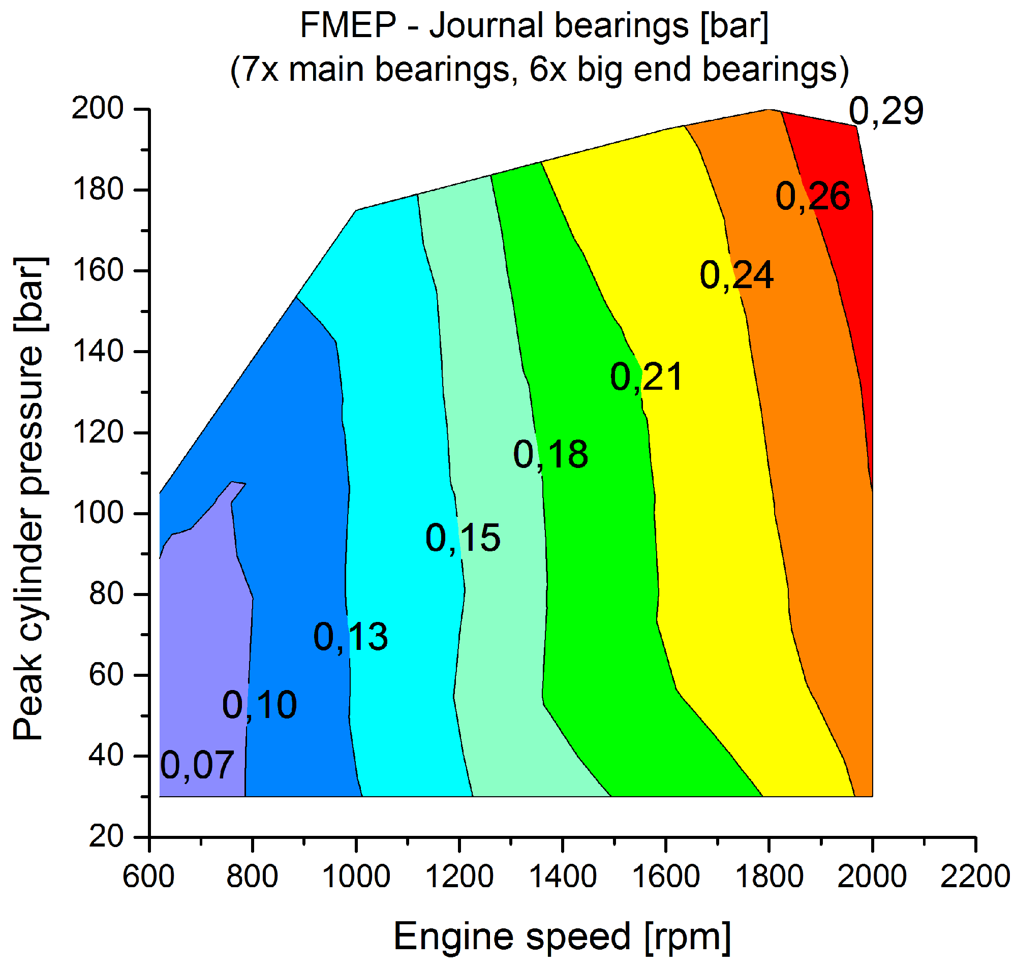
The described simulation is carried out for 107 different engine load and speed points. The results are shown as friction mean effective pressure (FMEP; the FMEP is calculated by dividing the frictional power by engine displacement per unit time) in
Figure 4 for the total of seven main and six big end bearings.
Figure 4.
Friction mean effective pressure (FMEP) in bar of the crank train journal bearings (seven main and six big end bearings) over engine speed and peak cylinder pressure. The peak cylinder pressure corresponds to the actual engine load.
Figure 4.
Friction mean effective pressure (FMEP) in bar of the crank train journal bearings (seven main and six big end bearings) over engine speed and peak cylinder pressure. The peak cylinder pressure corresponds to the actual engine load.
Despite that the bearing temperatures increase strongly for high engine speeds and loads, the results show still a strong dependence on engine speed and load. Under motored conditions the FMEP ranges already from 0.07 bar at 620 rpm engine speed up to 0.24 bar at 2000 rpm engine speed. For these conditions the FMEP shows a rather linear increase of 0.03 bar for every 200 rpm engine speed increase, which is also in agreement with previous measurements [
21]. It is interesting to note that this linear increase is present rather independently from the peak cylinder pressure (which corresponds to the actual engine load). As can also be noted in
Figure 4 and might not be intuitively expected, the FMEP of the crank train journal bearings is only weakly dependent on the peak cylinder pressure. As shown in
Figure 3, the main bearing temperature rises from 103
C up to 127
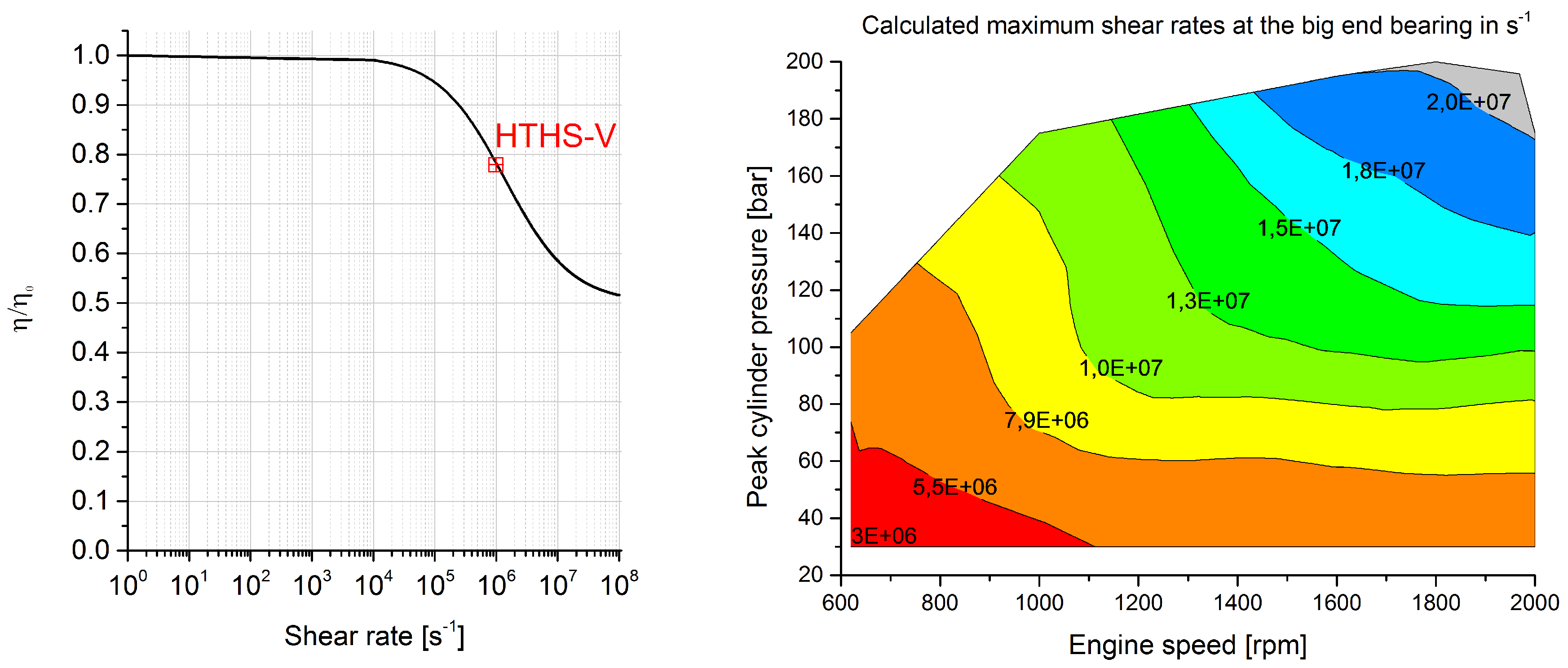
C from motored conditions to full load at an exemplary engine speed of 2000 rpm. This increase in temperature already results in a strong reduction of the lubricant viscosity in the journal bearings. In addition, high shear rates are present, see
Figure 5, which further lower the oil viscosity (see Equation (
1)). For the studied 5W30 lubricant the transition between the first to the second Newtonian regime occurs at shear rates of about
s
[
6]. As a consequence of this transition, the lubricant viscosity is even more reduced for shear rates at and above this value.
Figure 5.
Left: Non-Newtonian behaviour of the 5W30 lubricant; Right: Maximum shear rates calculated for the big end journal bearing.
Figure 5.
Left: Non-Newtonian behaviour of the 5W30 lubricant; Right: Maximum shear rates calculated for the big end journal bearing.
This decrease of lubricant viscosity due to temperature and shear rates compensates the increase of viscosity due to higher contact pressure as well as the rise of hydrodynamic friction due to the higher load. Together, this results in only a marginal increase of the journal bearings frictional losses over engine load compared to the effect of engine speed. This holds true as long as no significant metal-metal contact occurs. As the engine is operated with its recommended 5W30 lubricant the simulation predicts no significant metal-metal contact.
4.2. A Comparison to Other Engines
Further, it is interesting to compare the results for the investigated engine to literature. Unfortunately, papers dealing with the journal bearing friction losses of heavy-duty Diesel engines are rare. However, in [
22], a very similar engine, namely a 12.9 litre heavy-duty Diesel engine with six cylinders and inline configuration was investigated. The aim of the comparison is to investigate the trends of the frictional losses of the journal bearings of two different engines but with comparable engine displacement and power. To allow a direct comparison, additional calculations were carried out using the same temperature, load and speed conditions as well as the same lubricant (SAE) viscosity grade as published in [
22]. More precisely, the temperatures for coolant and lubricant are set to 90
C and only conventional motoring conditions with their low bearing loads are investigated.
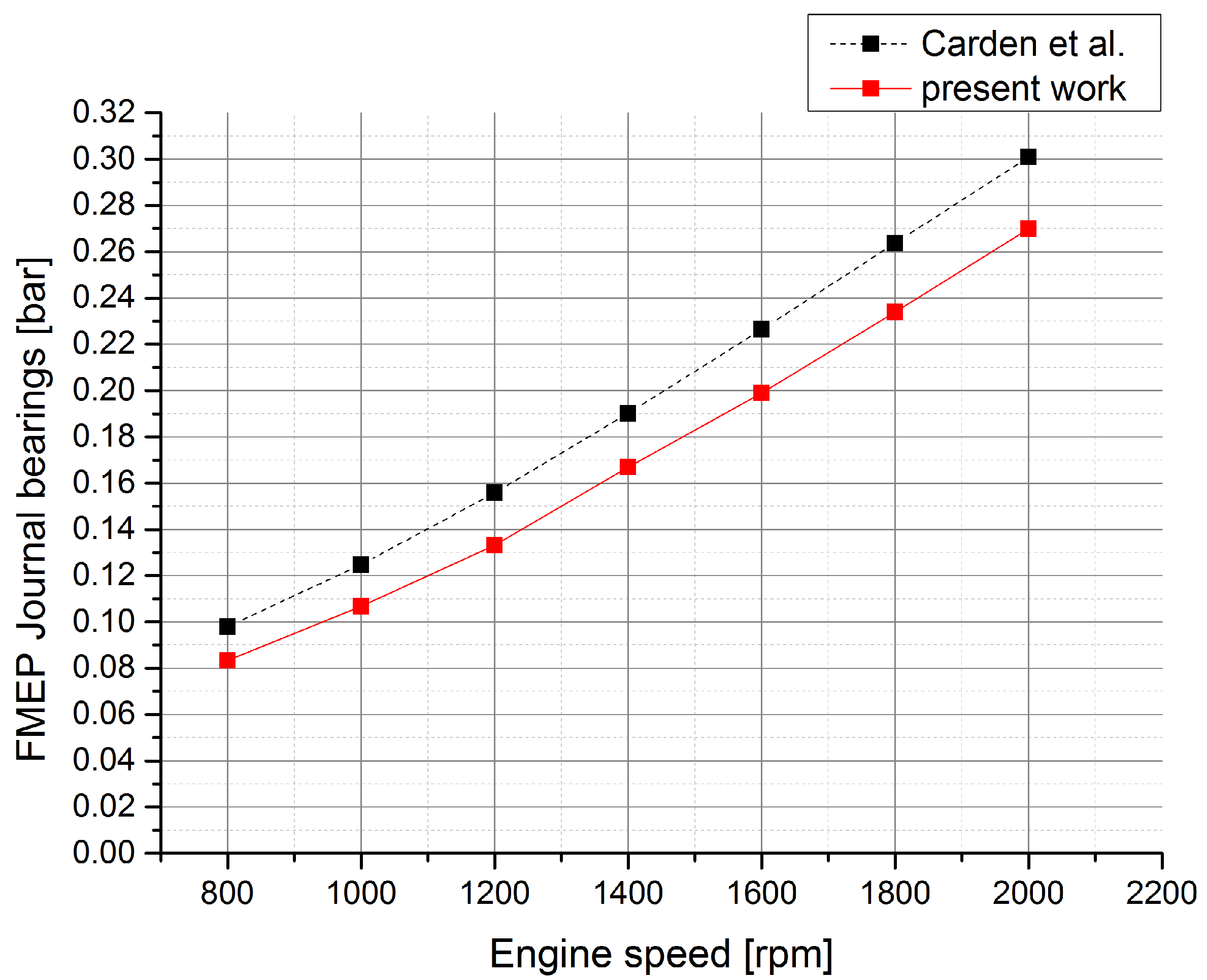
Figure 6 shows the results calculated for the engine investigated in this work in comparison to the results obtained for the engine in the cited work.
Figure 6.
Comparison of the journal bearing simulation results for the investigated heavy-duty engine with results from literature [
22] for a comparable engine.
Figure 6.
Comparison of the journal bearing simulation results for the investigated heavy-duty engine with results from literature [
22] for a comparable engine.
It is important to mention that the simulation methodology is different in the cited work [
22]. Therefore, the accuracy of the cited method is not clear. However, due to the very low loads and temperatures involved the exact details of the simulation methodology (consideration of the piezoviscous effect and the non-Newtonian behaviour) are less critical, so a comparison to derivate the trends of the frictional losses in the journal bearings is still meaningful. This is further supported by the fact that the journal bearing temperatures are almost identical to the oil supply temperature, see
Figure 3, where the equivalent bearing temperature relation (Equation (
2)) is not strictly needed as it gives only minor corrections. As can be seen in
Figure 6 the FMEP trends for the journal bearings are quite similar compared to the results from [
22] with only small differences. The minor deviations might indeed be attributed to the geometrical differences of the involved journal bearings.
4.3. Reducing Friction with Ultra-Low Viscosity Lubricants
The 5W30 lubricant class is widely used in the passenger car and heavy-duty industry; it is also the lubricant specified for the investigated engine. However, it is of interest to investigate also the potential for a further friction reduction in the journal bearings by using even lower viscosity lubricants. Therefore, an additional lubricant is studied, namely a 0W20 oil. By reducing the lubricant viscosity significantly, not only the power losses within the lubricant film decrease, but at the same time the likelihood of metal-metal contact increases. To ensure the same load carrying capability of the oil film, a 0W20 lubricant with the same HTHS-viscosity of 3.6 mPa s as the 5W30 lubricant is studied in the following;
Table 1 lists the rheological properties of both lubricants. A 0W20 lubricant with such a high HTHS viscosity needs to be extraordinarily shear stable to remain the conventional durability of the journal bearings. This oil film stability at high shear rates can decrease the advantages of the fuel-efficient engine oil by increasing the power losses within the oil film in comparison to an engine oil with a lower HTHS-viscosity. Therefore, also a more common 0W20 lubricant with a HTHS-viscosity of 2.8 mPa s is investigated having otherwise the same viscosity properties as the 0W20 listed in
Table 1.
Figure 7 shows the obtained results for an exemplary engine speed of 1000 rpm from idle up to full load operation for both the 5W30 baseline lubricant and the 0W20 lubricant with the 3.6 mPa s HTHS-viscosity. As expected, at full load the friction power losses of the two lubricants are almost identical. This is due to the high shear rates that occur at full load reducing the lubricant viscosity down to its HTHS-viscosity. As both lubricants have the same HTHS-viscosity, the friction power losses are very similar in this high load region.
For low part load operation with peak cylinder pressures of less than 120 bar, the reduced viscosity of the 0W20 lubricant yields a friction reduction of about 0.01 bar, which corresponds to a reduction of about 8%.
Figure 7.
Comparison of the FMEP of the main and big end journal bearings for two different lubricants: the FMEP for the 5W30 lubricant is shown as solid line and the FMEP for the 0W20 lubricant with a HTHS-viscosity of 3.6 mPa s is shown as dotted line.
Figure 7.
Comparison of the FMEP of the main and big end journal bearings for two different lubricants: the FMEP for the 5W30 lubricant is shown as solid line and the FMEP for the 0W20 lubricant with a HTHS-viscosity of 3.6 mPa s is shown as dotted line.
As outlined at the beginning of this section, the studied 0W20 lubricant is required to be extremely shear stable with a HTHS-viscosity of 3.6 mPa s. Therefore, a more common 0W20 lubricant with a HTHS-viscosity of 2.8 mPa s is investigated in addition. However, the analysis with the reduced HTHS-viscosity lubricant showed a strong presence of metal-metal contact under full load operation already at 1000 rpm engine speed. As the inertia forces increase with increasing engine speed, the amount of metal-metal contact will be even more severe for higher engine speeds. As a consequence, it is concluded that for the present engine construction a HTHS-viscosity of 3.6 mPa s represents an optimum value at least for the journal bearings. A further HTHS-viscosity reduction is expected to require additional efforts to maintain the high service life that is obtained with lubricants having a HTHS-viscosity of 3.6 mPa s.
In [
23] also the potential for low and ultra-low viscosity lubricants is investigated for the same engine that was already investigated in [
22]. However, this was conducted experimentally and for the entire engine friction, so no journal bearing specific results could be obtained. When comparing these two works it is important to note that in [
22,
23] the oil temperature was always maintained at 90
C. In this work the oil sump temperature could freely settle depending on the operating load and speed, which resembles real-world operation much closer. In any case, the oil temperature in this work could increase to as much as 120
C.
It was, however, found [
23] that the benefit of changing to a lower viscosity lubricant (the
LV termed lubricant in the cited work is comparable to the 0W20 oil with the HTHS-viscosity of 2.8 mPa s in this work) could not be seen consistently in all results. This might be due to insufficient measurement accuracy as even lower viscosity lubricants do showed clear advantages. Still a reduction in fuel consumption of about 0.6% could be determined using the low viscosity lubricant for the investigated ESC test cycle presented in the cited work. In particular the improvements were determined to be greatest for low loads and lowest for the high load points, which is in perfect agreement with the results presented in this work.
