3.1. TEHD Mechanism
To analyze the TEHD mechanism of the mechanical seal, the above-mentioned numerical procedure is conducted on the deep-grooved mechanical seal under the conditions of p = 15 MPa and n = 2000 rpm in the study.
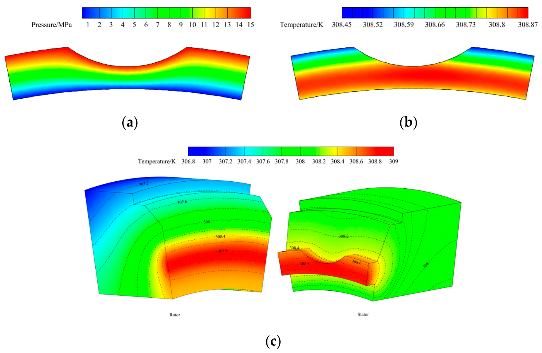
Figure 7 presents the contour graph of the pressure and temperature distribution of the fluid film under the conditions of
po = 15 MPa and
n = 2000 rpm. From
Figure 7a, it can be observed that no cavitation occurs in the fluid film under the present condition. The pressure of the fluid film decreases gradually from the outer side to the inner side. The maximum pressure of the fluid film is 15 MPa, indicating that no significant hydrodynamic effect is generated in the fluid film. The pressure distribution is closely dependent on the distribution of the fluid film thickness presented in
Figure 8a.
The temperature distribution on the seal face is consistent with that of the fluid film. The temperature of the fluid film exhibits a gradual increase from the outer side to the inner side, and it reaches a maximum value at the middle-diameter position near the inner side of the seal face, as shown in
Figure 7b,c. This is because the outer side serves as the convective heat transfer boundary with the fluid medium, while the inner side performs convective heat transfer with the atmosphere. Greater convection occurs at the outer side of the seal face. Meanwhile, the heat generated by fluid leakage also increases the fluid film temperature near the groove region, resulting in an increase in the fluid film temperature. The maximum temperature on the seal face is approximately 308.8 K, while the temperature difference between the inner and outer sides is relatively small. The temperature differences across the seal face result in thermal deformation of the seal face. Due to the rotational action of the rotor, the temperature distribution along the circumferential direction is relatively uniform, resulting in minimal circumferential variation in the thermal deformation of the seal face.
The distribution of the fluid film thickness under the corresponding conditions of
po = 15 MPa and
n = 2000 rpm is shown in
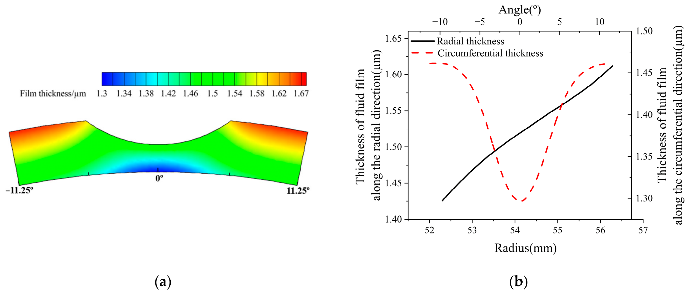
Figure 8. The fluid film profile is caused by the deformation of the seal face. From
Figure 8a, it can be seen that the maximum film thickness of about 1.67 μm appears at the outer side of the sealing gap, corresponding to the high-pressure region of the fluid film. The minimum thickness of the fluid film is about 1.3 μm and occurs at the inner side, which indicates that the hydrostatic effect of the fluid film makes the seal face of the mechanical seal operate in a non-contacting state. It can be concluded that the mechanical seal operates in the state of full-film lubrication under the current condition [
21]. The fluid film thickness gradually decreases from the outer side to the inner side, indicating that there is an obvious taper along the leakage direction, and a convergent sealing gap is generated.
Figure 8b presents the distribution of the fluid film thickness at a radius of 52.3 mm and at an angle of 5.625° for the description of the circumferential and radial results, respectively. The fluid film thickness along the radial direction decreases from the outer side to the inner side, and the thickness difference is about 0.19 µm at the angle of 5.625°. The fluid film thickness along the circumferential direction has a waviness with an amplitude of about 0.165 µm at a radius of 52.3 mm. This phenomenon indicates that a hydrodynamic effect is generated, although the amplitude of the circumferential waviness is small, facilitating the generation of a thermo-hydrodynamic wedge effect. Consequently, it is concluded that the load-carrying capacity of the fluid film in the deep-grooved face seal predominantly relies on the hydrostatic effect, and there is a relatively minor contribution from the hydrodynamic effect, which is consistent with the results in Reference [
11].
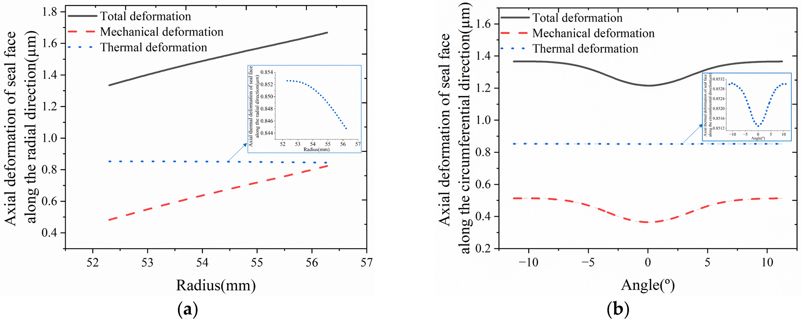
Figure 9 presents the total axial deformation distribution of the seal face under the conditions of
po = 15 MPa and
n = 2000 rpm, including the axial mechanical and axial thermal deformation. Here, the results at a radius of 52.3 mm and at an angle of 5.625° are also presented for the description of the circumferential and radial results.
In the total axial deformation of the seal face, the axial thermal deformation is predominant compared to the axial mechanical deformation. In
Figure 9a, it is apparent that the axial mechanical deformation of the seal face decreases from the outer side to the inner side of the seal face along the radial direction, with a deformation difference of approximately 0.342 μm between the inner and outer sides. In contrast, the axial thermal deformation of the seal face decreases from the inner side to the outer side along the radial direction due to the higher temperature near the inner side, although the temperature difference across the seal face is relatively small. The maximum magnitude of the axial thermal deformation along the radial direction is approximately 0.85 μm, and the difference in the axial thermal deformation along the radial direction between the maximum and minimum values is only about 0.008 μm. This indicates that the variation in the axial thermal deformation along the radial direction is very small. Therefore, it can be concluded that the axial thermal deformation along the radial direction remains nearly uniform due to the small temperature difference, as shown in
Figure 7c, despite being larger than the axial mechanical deformation, with a maximum of approximately 0.82 μm at the outer side.
Since the variation trend of the axial thermal deformation is opposite to that of the axial mechanical deformation along the radial direction, the axial thermal deformation partially counteracts the radial taper induced by the axial mechanical deformation. Under the combined effect of both deformations, the total axial deformation of the seal face along the radial direction exhibits a gradually decreasing trend from the outer side to the inner side of the seal face, which results in a convergent fluid film profile. The difference in the total axial deformation of the seal face along the radial direction between the inner and outer sides is about 0.334 μm.
Figure 9b presents the axial deformation of the seal face along the circumferential direction. Both the axial mechanical and thermal deformations exhibit waviness variations along the circumferential direction, and they have a consistent variation trend along the circumferential direction. Accordingly, the circumferential waviness amplitude of the total axial deformation, with a magnitude of approximately 0.15 μm, is the result of the direct superposition of both deformations.
Although the axial thermal deformation along the circumferential direction is relatively larger than that of the axial mechanical deformation, the circumferential waviness amplitude of the axial thermal deformation is approximately 0.0018 μm, which is significantly smaller than that of the axial mechanical deformation with a magnitude of approximately 0.149 μm. No significant variation in the circumferential waviness for the axial thermal deformation occurs due to the relatively uniform temperature distribution along the circumferential direction shown in
Figure 7c, and there is minimal impact on the thermo-hydrodynamic wedge effect. This differs from Mayer et al.’s conclusion that deep grooves produce strong cooling effects and generate significant circumferential waviness [
22,
23]. Unlike the axial thermal deformation, the axial mechanical deformation of the seal face varies significantly along the circumferential direction, and the amplitude of circumferential waviness caused by the axial mechanical deformation is about 0.149 μm. This indicates that the thermo-hydrodynamic wedge effect of the seal face is primarily dominated by the mechanical deformation, while the thermal deformation plays a relatively minor role despite its larger magnitude. This is because the axial thermal deformation of the seal face is relatively uniform without generating significant gradients along the radial and circumferential directions, due to the small temperature gradient across the seal face shown in
Figure 7c. In contrast, the axial mechanical deformation varies significantly and produces significant spatial gradients in both the radial and circumferential directions due to the non-uniform pressure distribution acting on the seal face, despite being smaller in magnitude compared with thermal deformation.
Compared to the total axial deformation of the seal face along the circumferential direction, the total axial deformation of the seal face along the radial direction exhibits a relatively larger magnitude. Consequently, the resulting hydrostatic effect is crucial for ensuring the stable operation of the mechanical seal.
In the present study, due to the relatively uniform temperature distribution of the seal face along the radial and circumferential directions shown in
Figure 7c, the radial taper and circumferential waviness effect induced by the thermal deformation is minimal. This implies that the cooling effect from the deep grooves has a non-significant influence on radial taper and circumferential waviness, and the thermal effect plays a relatively minor role in the thermo-hydrodynamic wedge effect. It is worth noting that in the work of Mayer et al. [
22,
23], the deep-grooved mechanical seal operates with a small film thickness of approximately 0.2~1 μm [
22]. Under this thin-film lubrication condition, substantial viscous shear heat is generated, potentially accompanied by contact-induced heating, resulting in a pronounced temperature rise in the seal ring. Furthermore, their research primarily focuses on seal rings with relatively smaller diameters (<100 mm), and notable differences exist in the groove location on the seal ring, width of seal face, material, number of grooves, and groove dimensions compared to the present study. In addition, the rotational speed in our study is within the range of 2500 rpm, whereas Mayer et al.’s work operated under high-speed conditions larger than 3000 rpm. These discrepancies in operating conditions, geometric configurations, and material parameters account for the differences observed between the conclusions of the two studies.
3.2. Deformation Characteristics at Different Fluid Pressures
To further investigate the deformation characteristics and the sealing performance of the mechanical seal, the influence of the operating conditions is focused on in the research. The numerical calculation is conducted on the deep-grooved mechanical seal under the conditions of psp = 0.27 MPa and n = 2000 rpm in the study. Here, the characteristics at the radius of 52.3 mm and at the angle of 5.625° are also presented for the description of the circumferential and radial results, respectively.
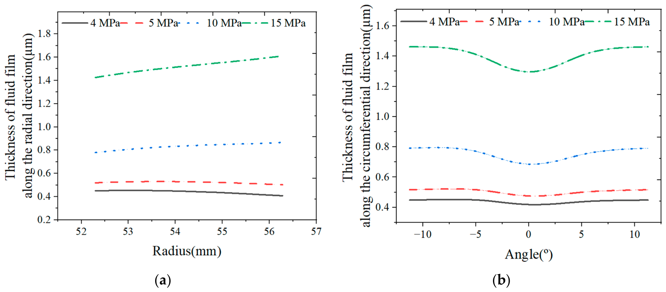
The distribution of the fluid film thickness under different fluid pressures is described in
Figure 10. Due to the increased pressure difference causing greater mechanical deformation, the fluid film thickness along the radial direction and the radial taper of the fluid film gradually increase, and the location of the maximum thickness along the radial direction gradually shifts toward the outer side, as shown in
Figure 10a. When the pressure is larger than 5 MPa, the maximum thickness of the fluid film along the radial direction occurs at the outer side; otherwise, it occurs at the inner side. The thickness difference at the inner and outer sides along the radial direction reaches its maximum value at a pressure of 15 MPa, and it is about 0.19 μm.
From
Figure 10b, it can be seen that a similar variation trend occurs for the fluid film thickness along the circumferential direction at different fluid pressures. The circumferential thickness of the fluid film also increases with an increase in the fluid pressure, and the amplitude of the circumferential waviness also gradually grows from about 0.034 μm to 0.165 μm, indicating that the thermo-hydrodynamic wedge effect of the seal face becomes more pronounced as pressure increases. Thus, it can be concluded that an increase in the fluid pressure enhances the hydrostatic effect of the fluid film.
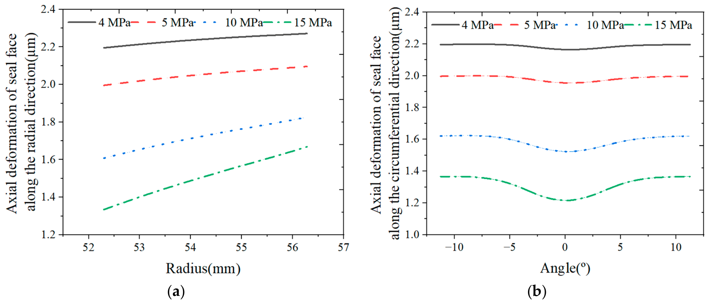
The total axial deformation characteristics of the seal face under different fluid pressures are described in
Figure 11.
A similar trend also occurs for the deformation of the seal face at different fluid pressures. As shown in
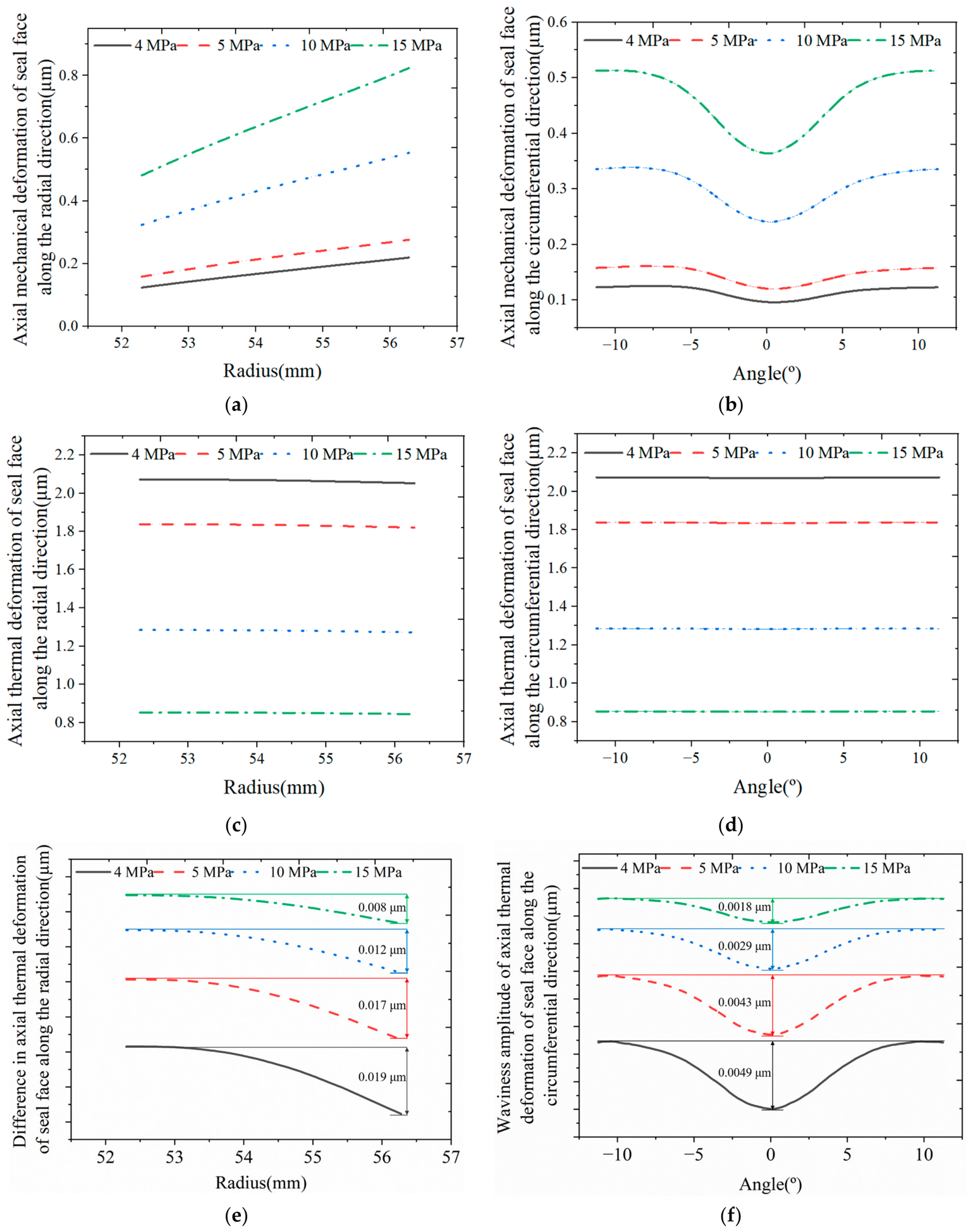
Figure 11a, the maximum total axial deformation displacement along the radial direction can be obtained at the outer side, and the minimum total axial deformation occurs at the inner side at different fluid pressures. Due to the increased fluid film thickness leading to a reduced temperature rise, the axial thermal deformation of the seal face along both the radial and circumferential directions exhibits a decreasing trend with increasing fluid pressure, and it presents a relatively uniform distribution along the radial and circumferential directions due to the small temperature gradient across the seal face, as shown in
Figure 12c,d.
Furthermore, with axial thermal deformation being dominant on the seal face, it is apparent from
Figure 11 that the total axial deformation of the seal face along the radial and circumferential directions decreases gradually with the increase in fluid pressure, while the radial taper and the amplitude of the circumferential waviness gradually increase, reaching approximately 0.334 μm in axial deformation difference along the radial direction between the inner and outer side of the seal face and 0.15 μm in amplitude of the circumferential waviness in the given range, which is primarily induced by the larger displacement gradient in axial mechanical deformation along both the radial and circumferential directions for increased fluid pressure, as presented in
Figure 12a,b. At different fluid pressures, the axial mechanical deformation along the radial direction increases from the inner side to the outer side. In the given range, the maximum axial mechanical deformation of about 0.82 μm is obtained at the outer side at a pressure of 15 MPa, and the difference in axial mechanical deformation along the radial direction between the inner and outer sides of the seal face increases from approximately 0.1 μm to 0.342 μm. Meanwhile, the amplitude of the circumferential waviness in the axial mechanical deformation increases as the fluid pressure increases, reaching approximately 0.149 μm at a pressure of 15 MPa.
In contrast, the axial thermal deformation presents a relatively uniform distribution along both the radial and circumferential directions due to the small temperature gradient across the seal face, as shown in
Figure 12c,d. The difference between the maximum and minimum values along the radial direction decreases from 0.019 μm to 0.008 μm, and the amplitude of the circumferential waviness decreases from 0.0049 μm to 0.0018 μm in the given range, as presented in
Figure 12e,f, respectively. The axial mechanical deformation of the seal face governs the circumferential waviness of the film profile. The thermo-mechanical coupling deformation of the seal face results in a convergent taper between the inner and outer sides of the seal face.
Therefore, based on the above analysis, it can be confirmed that the hydrodynamic effect of the fluid film originates primarily from the axial mechanical deformation of the seal face and becomes progressively weaker as the fluid pressure increases due to the dominant hydrostatic effect.
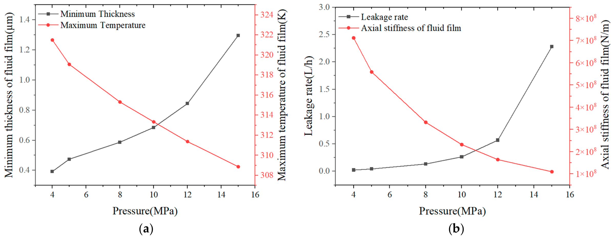
Figure 13 presents the sealing performance of the mechanical seal at different fluid pressures, where the axial stiffness, maximum temperature, minimum thickness of the fluid film, and the leakage rate are mainly focused on. As the fluid pressure increases, the fluid film thickness increases, which results in a decrease in the maximum temperature and the axial stiffness of the fluid film, and consequently an increase in the leakage rate. The leakage rate is about 0.023 L/h, and the axial stiffness of the fluid film is about 7.12 × 10
8 N/m at a pressure of 4 MPa. The reason why the axial stiffness of the fluid film is reduced is that a large film thickness is detrimental to maintaining sealing stability. Due to the balance between the opening force and closing force of the fluid film, the increased radial taper shown in
Figure 9 results in an increase in the minimum thickness of the fluid film.
To further evaluate the influence of fluid pressures on the sealing performance of the present deep-grooved mechanical seal, a local sensitivity analysis is conducted based on the dimensionless relative sensitivity coefficient. The local sensitivity coefficient
Si is defined as follows:
where the subscript
i represents a specific index or identifier;
Y denotes the value of the sealing performance parameter, such as leakage rate or film thickness, at operating condition;
Yo is the reference value of the sealing performance parameter;
Xi represents the
i-th operating parameter, for example, fluid pressure or rotational speed; and
Xi,o denotes the corresponding reference value of the
i-th operating parameter.
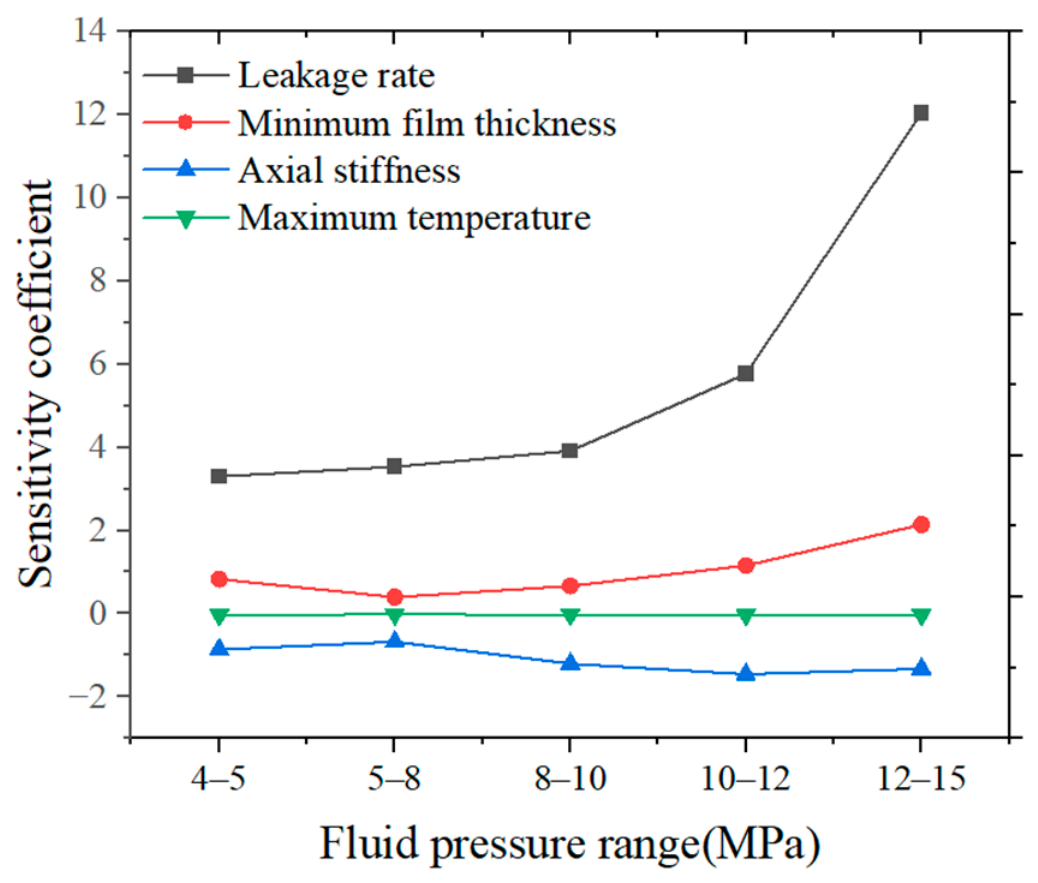
The sensitivity coefficients of the leakage rate, minimum film thickness, axial stiffness, and maximum temperature of the fluid film under different fluid pressure conditions are illustrated in
Figure 14. It can be seen that the sensitivity coefficient of the leakage rate with respect to fluid pressure exhibits a pronounced increasing trend, ranging from approximately 3.30 to 12.04, indicating that the leakage rate becomes increasingly sensitive to fluid pressure variations at higher pressure levels. Similarly, the sensitivity coefficient of the minimum film thickness with respect to fluid pressure also presents an upward trend in the relatively high-pressure region (larger than 5 MPa), increasing from approximately 0.40 to 2.14. However, in the relatively low-pressure region (below 5 MPa), its sensitivity coefficient is about 0.83, demonstrating a higher sensitivity to fluid pressure variations compared to the initial stage of the high-pressure region. Conversely, the sensitivity coefficients of both the axial stiffness and maximum temperature of the fluid film are negative, indicating that an increase in fluid pressure leads to a reduction in both the axial stiffness and temperature of the fluid film. The maximum sensitivity coefficient of the axial stiffness reaches about −1.46 within the given pressure range. Specifically, a 1% increase in fluid pressure results in approximately a 1.46% reduction in axial stiffness. In contrast, the maximum temperature exhibits low sensitivity to fluid pressure variations, with sensitivity coefficients of about −0.03 below 5 MPa and −0.032 above 5 MPa. In summary, fluid pressure exerts a significant influence on the leakage rate, especially under high-pressure conditions, whereas its impact on the maximum temperature of the fluid film remains marginal.
3.3. Deformation Characteristics at Different Spring Forces
The numerical calculations on the deformation characteristics at different spring forces are conducted on the deep-grooved mechanical seal under the conditions of po = 15 MPa and n = 2000 rpm in the study. The spring force, in the form of the spring specific pressure, ranges from 0.23 MPa to 0.29 MPa in this part. Here, the characteristics at the radius of 52.3 mm and at the angle of 5.625° are also presented for the description of the circumferential and radial results, respectively.
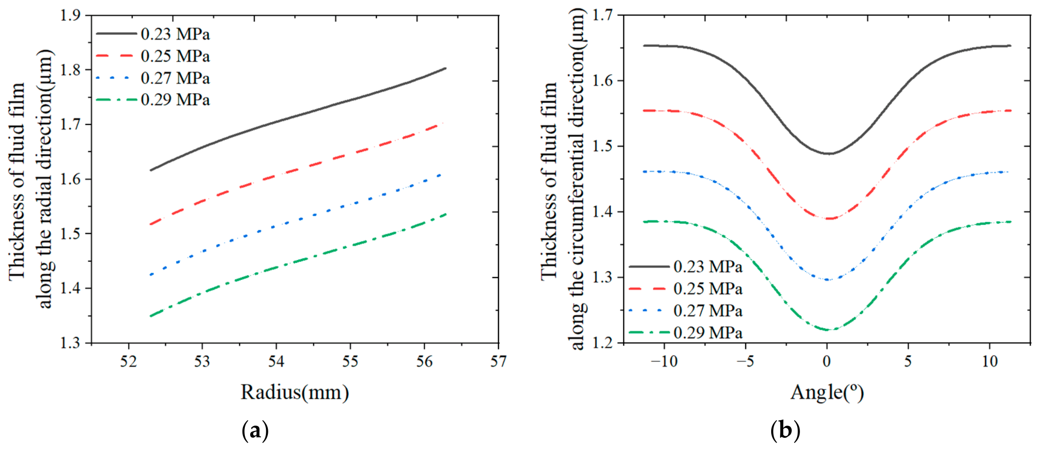
Figure 15 presents the distribution of the fluid film thickness under different spring specific pressures.
With the increase in the spring specific pressure, the radial and circumferential thickness of the fluid film both decrease. The maximum radial thickness of the fluid film is also obtained on the outer side. However, there is no significant variation in the radial taper and circumferential waviness of the fluid film as the spring specific pressure increases, with the amplitude of the waviness remaining about 0.17 μm, as shown in
Figure 15b. This indicates that the thermo-hydrodynamic wedge effect of the seal face is not enhanced as the spring specific pressure increases.
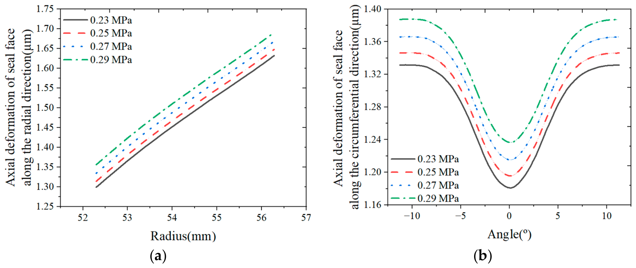
The deformation characteristics of the seal face under different spring specific pressures are described in
Figure 16. A similar trend is also observed for the total axial deformation of the seal face at different spring specific pressures. As shown in
Figure 16a, the maximum deformation along the radial direction can be obtained at the outer side, and it can reach up to 1.69 μm at the spring pressure of 0.29 MPa. The minimum deformation along the radial direction is generated at the inner side, and the minimum value is about 1.3 μm at the spring pressure of 0.23 MPa. Due to the reduced fluid film thickness leading to an increased temperature rise, the axial deformation of the seal face along the radial and circumferential directions increases gradually with the increase in spring specific pressure, while no significant variation occurs in the radial taper and circumferential waviness shown in
Figure 16b. It can be concluded that there is little difference in the thermo-hydrodynamic wedge effect at different spring specific pressures.
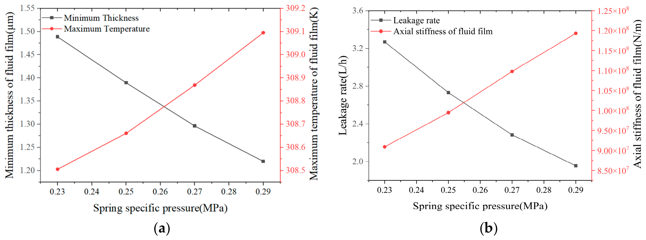
Figure 17 presents the sealing performance of the mechanical seal at different spring specific pressures. Due to the reduced thickness of the fluid film caused by the increased spring specific pressure, the leakage rate and minimum thickness of the fluid film decrease, and the maximum temperature and axial stiffness of the fluid film are enhanced. At a spring specific pressure of 0.29 MPa, although the minimum thickness of the fluid film is about 1.22 μm, the axial stiffness of the fluid film is about 1.19 × 10
8 N/m, and the leakage rate is smaller than 2.0 L/h. That is why a smaller fluid film thickness is beneficial for sealing stability.
To further evaluate the influence of spring specific pressure on the sealing performance of the present deep-grooved mechanical seal, a local sensitivity analysis is also performed based on the dimensionless relative sensitivity coefficient.
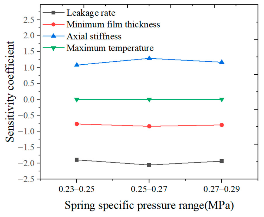
The sensitivity coefficients of the leakage rate, minimum thickness, axial stiffness, and maximum temperature of the fluid film under different spring specific pressures are described in
Figure 18.
As shown in
Figure 18, the sensitivity coefficients of the performance parameters with respect to spring specific pressure exhibit no significant upward or downward trends, indicating a relatively stable sensitivity in the given range. Specifically, the sensitivity coefficient of the leakage rate with respect to spring specific pressure remains approximately constant at around −2.0 across all intervals (ranging from −1.89 to −2.05). This negative value also signifies an inverse relationship, implying that an increase in spring specific pressure leads to a reduction in the leakage rate. Similarly, the sensitivity coefficient of minimum film thickness with respect to spring specific pressure remains stable at approximately −0.8 across all intervals (ranging from −0.77 to −0.84). In contrast, the sensitivity coefficients of the axial stiffness and maximum temperature are positive, suggesting that increasing the spring specific pressure enhances the axial stiffness and temperature of the fluid film. The maximum sensitivity coefficient of the axial stiffness reaches approximately 1.29 within the given range. Conversely, the maximum sensitivity coefficient of the maximum temperature of the fluid film is merely 0.0099, indicating a very low sensitivity to the variation in the spring specific pressure. In summary, the influence of spring specific pressure on the performance parameters is relatively stable under the operating conditions in which the influence on the leakage rate is more significant, and the impact on the temperature of the fluid film also remains insignificant.
3.4. Deformation Characteristics at Different Rotational Speeds
The deformation characteristics at different rotational speeds are conducted on the deep-grooved mechanical seal under the conditions of po = 15 MPa and psp = 0.27 MPa, and the rotational speed is ranged from 500 rpm to 2500 rpm in this part. Here, the characteristics at the radius of 52.3 mm and at the angle of 5.625° are also presented for the description of the circumferential and radial results, respectively.
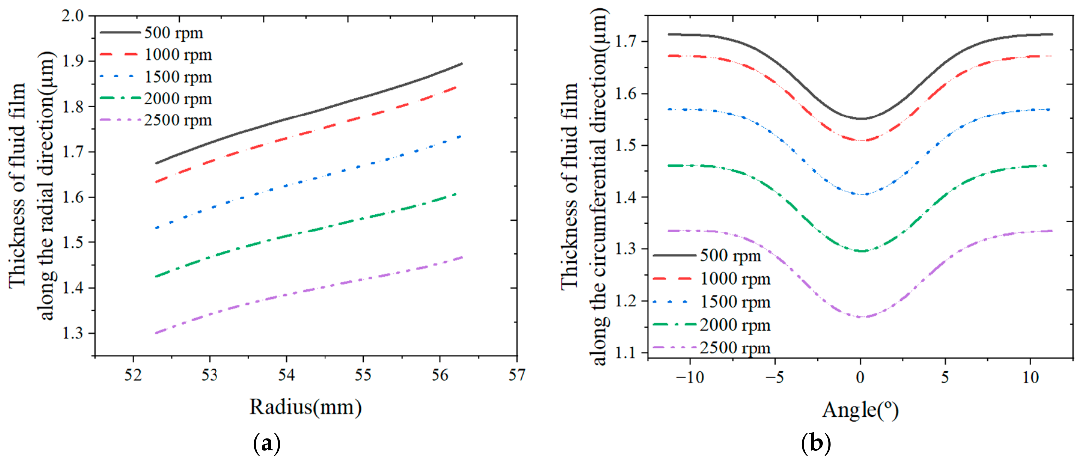
Figure 19 presents the distribution of the fluid film thickness under different rotational speeds. Due to the increased viscous shear heat, the film temperature increases, and the fluid viscosity is reduced, thereby diminishing the hydrodynamic effect. As a result, the load-carrying capacity of the fluid film decreases. The thickness of the fluid film along the radial and circumferential directions decreases as the rotational speed increases. The maximum and minimum values of the fluid film thickness along the radial direction can also be obtained at the outer and inner sides, respectively. In
Figure 19, although there is no significant variation in the radial taper and circumferential waviness of the fluid film as the rotational speed increases, the radial taper presents a decreasing trend, and the amplitude of the circumferential waviness shows an increasing trend as the rotational speed increases in the given range. As shown in
Figure 19a, the difference in the fluid film thickness along the radial direction between the inner and outer sides decreases from about 0.22 μm to 0.16 μm as the rotational speed increases. This is because the enhanced viscous shear heat at high speeds elevates the film temperature and induces greater thermal deformation of the seal face, which partially counteracts the convergent taper produced by the mechanical deformation, and consequently the film thickness difference along the radial direction between the inner and outer sides is decreased.
In addition, with increasing rotational speed, the viscous shear effect in the fluid film increases, which would generally enhance the hydrodynamic effect. However, as discussed above, the intensified shear heat reduces the viscosity and diminishes the hydrodynamic effect. As a result, the increase in the amplitude of the circumferential waviness of the film thickness is very small. As shown in
Figure 19b, the amplitude of the circumferential waviness for the fluid film thickness increases from about 0.163 μm to 0.167 μm as the rotational speed increases in the given rotational speed range at a fluid pressure of 15 MPa, corresponding to an increase of approximately 2.5%. This small variation further confirms that the hydrodynamic effect is limited under the studied conditions. The load-carrying capacity of the fluid film predominantly relies on the hydrostatic effect.
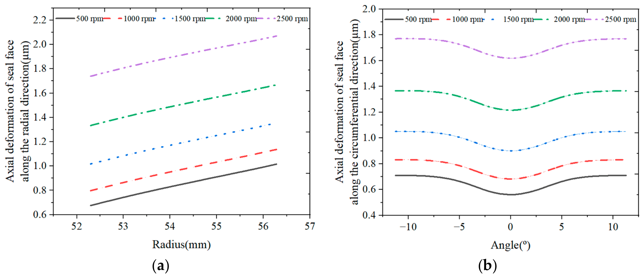
Figure 20 presents the total axial deformation characteristics of the seal face under different rotational speeds.
The total axial deformation of the seal face along the radial and circumferential directions increases as the rotational speed increases, while there are marginal variations in the radial taper and circumferential waviness of the total axial deformation of the seal face. Specifically, as shown in
Figure 20a, the difference in the total axial deformation of the seal face along the radial direction between the inner and outer sides decreases from approximately 0.339 μm to 0.330 μm, because the axial thermal deformation partially offsets the radial taper induced by the axial mechanical deformation. Concurrently, the amplitude in the circumferential waviness of the total axial deformation increases from approximately 0.148 μm to 0.152 μm in
Figure 20b due to the enhanced hydrodynamic effect as the rotational speed increases. This minor change indicates that the thermo-hydrodynamic wedge effect of the seal face is not significantly enhanced as the rotational speed increases.
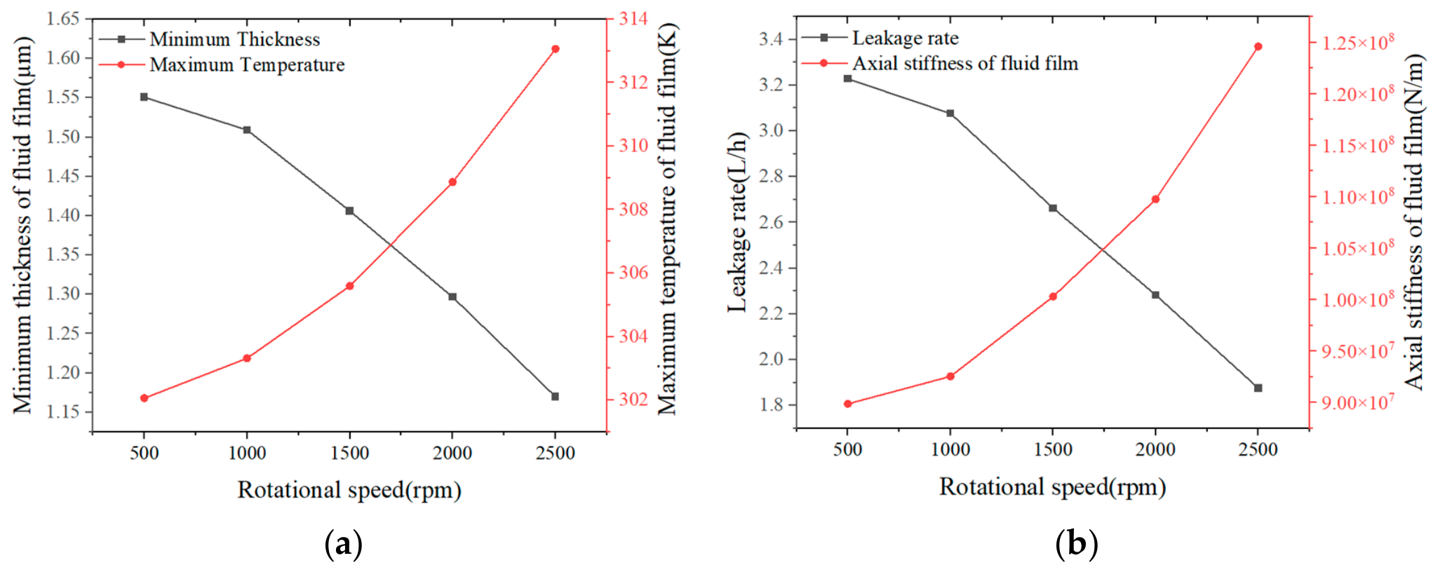
Figure 21 presents the sealing performance of the mechanical seal at different rotational speeds. As mentioned above, the load-carrying capacity decreases with increasing rotational speed. Accordingly, the minimum thickness of the fluid film also decreases as the rotational speed increases, and the minimum thickness of the fluid film is about 1.17 μm at a rotational speed of 2500 rpm in the given range. Consequently, the reduced thickness of the fluid film results in a decreased leakage rate and an increased axial stiffness of the fluid film with increasing rotational speed. The minimum leakage rate of about 1.88 L/h is obtained at a rotational speed of 2500 rpm in the given range.
The maximum temperature and axial stiffness of the fluid film are enhanced with increasing rotational speed, caused by the reduced fluid film thickness. The maximum axial stiffness of the fluid film of about 1.25 × 10
8 N/m is obtained at a rotational speed of 2500 rpm in the given range. The larger the maximum temperature of the fluid film, the greater the axial thermal deformation of the seal face. However, the axial thermal deformation has little effect on the radial taper and circumferential waviness of the seal face, resulting in no significant variation in radial taper and amplitude of the circumferential waviness of the total axial deformation of the seal face with the increase in rotational speed, consistent with the above-mentioned results shown in
Figure 20.
To further evaluate the influence of rotational speed on the sealing performance of the present deep-grooved mechanical seal, a local sensitivity analysis is also carried out based on the dimensionless relative sensitivity coefficient.
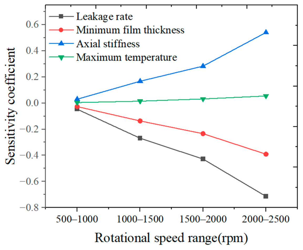
The sensitivity coefficients of the leakage rate, minimum thickness, axial stiffness, and maximum temperature of the fluid film with respect to rotational speed are presented in
Figure 22. It can be seen that significant upward trends occur in the sensitivity coefficients of the performance parameters with respect to rotational speed. Specifically, the sensitivity coefficients of the leakage rate and minimum film thickness with respect to rotational speed increase in magnitude from 0.047 to 0.71 and from 0.027 to 0.39, respectively. Although the absolute values of the sensitivity coefficients of the leakage rate with respect to rotational speed are lower than those to fluid pressure and spring specific pressure, the monotonically increasing trend in magnitude indicates that the influence of rotational speed on leakage rate becomes more pronounced at higher speeds. In contrast, the sensitivity coefficients of axial stiffness and maximum temperature of the fluid film increase from 0.029 to 0.54 and from 0.0042 to 0.054, respectively. The maximum temperature of the fluid film has relatively low sensitivity to variation in the rotational speed. In summary, rotational speed exerts a more pronounced influence on the leakage rate under the given operating conditions, especially at high speeds, while its impact on the maximum temperature of the fluid film remains relatively insignificant.
Based on the above-mentioned analysis of the sensitivity coefficients of the performance parameters under different operating conditions, the leakage rate exhibits the most significant sensitivity to the operating parameters, including fluid pressure, spring specific pressure, and rotational speed, while the maximum temperature of the fluid film presents the lowest sensitivity. Specifically, under the given operating conditions, the leakage rate is most sensitive to fluid pressure (with a sensitivity coefficient reaching 12.04), moderately and stably sensitive to spring specific pressure (with a sensitivity coefficient of approximately −2.0), and least sensitive to rotational speed (with a maximum sensitivity coefficient magnitude of approximately 0.7), although its influence intensifies at higher speeds. By comparison, the maximum sensitivity coefficient of the maximum fluid film temperature is merely approximately 0.054 within the given range.
In contrast, the sensitivities of the axial stiffness and minimum film thickness exhibit an intermediate trend under different operating conditions. However, under a relatively high-pressure range (larger than 12 MPa), the sensitivity coefficient of the minimum film thickness reaches up to 2.14, which exceeds the maximum magnitude of the sensitivity coefficient of the axial stiffness (approximately 1.46) in the given pressure range. Conversely, when considering variations in spring specific pressure and rotational speed, the axial stiffness is relatively more sensitive to these operating parameters than the minimum film thickness.