Review

A Review of Gear Wear and Transmission System Dynamics: Coupling Mechanisms, Influencing Factors, and Profile Modification Strategies


1
Beijing Engineering Research Center of Precision Measurement Technology and Instruments, Beijing University of Technology, Beijing 100124, China
2
Zhejiang XiaSha Precision Manufacturing Co., Ltd., Rongji Street, Luotuo Industrial Estate, Ningbo 315100, China
*
Author to whom correspondence should be addressed.
Lubricants 2026, 14(9), 334; https://doi.org/10.3390/lubricants14090334
Submission received: 29 July 2026 / Revised: 26 August 2026 / Accepted: 26 August 2026 / Published: 27 August 2026

Abstract

Gear wear is a tribological surface damage process caused by contact loading and relative motion between meshing tooth flanks. It involves progressive material removal or transfer, changes tooth-flank topography, and consequently affects contact conditions, mesh stiffness, transmission error, and dynamic response. This paper reviews recent advances in gear wear research, including typical tooth-surface damage, wear prediction under various lubrication conditions, tribodynamic behavior, dynamic effects of wear, and the influence of assembly errors, parameter uncertainties, and gear modification on meshing characteristics. Existing studies have progressed from isolated descriptions of wear to integrated analyses involving lubrication, surface condition, and dynamics. Nevertheless, the long-term bidirectional coupling between wear evolution and tribodynamics remains insufficiently understood, while the effects of assembly errors and multi-source uncertainties have received limited attention. Gear modification studies have also focused mainly on initial transmission performance rather than its sustained role during wear degradation. Future research should therefore establish coupled wear–friction dynamic models and develop wear analysis methods that account for actual assembly conditions and parameter uncertainties.

1. Introduction

Gears are fundamental transmission elements widely used in numerous industries. Owing to their high transmission accuracy, efficiency, and structural compactness, they are widely used in aerospace, wind power generation, heavy-duty vehicles, precision instruments, and other fields. As critical components of transmission systems, gears inevitably undergo tooth-flank wear with increasing service time. Tooth-flank wear is a continuous material loss process throughout the gear service life. During the running-in period, local asperity peaks are progressively smoothed, and the actual contact condition evolves. The wear rate is initially relatively high but generally decreases as the contacting surfaces adapt. Appropriate running-in can improve contact conformity, transmission efficiency, and subsequent wear behavior. This service-induced evolution may locally produce tooth engagement effects similar to those associated with a small tip relief modification; however, running-in results from material removal during operation, whereas tip relief is an intentional geometric correction introduced before service. The dynamic factor KV used in ISO 6336 [1] provides a design-oriented measure of dynamic load effects and is relevant when changes in tooth engagement caused by running-in or profile modification are evaluated. After running-in, the gear enters the steady wear stage, during which the wear rate remains relatively stable and the accumulated wear increases approximately linearly with time. As service time further increases, material fatigue, aging, and other factors degrade gear performance and accelerate wear. During severe degradation, wear may accelerate further and coexist with damage such as pitting and cracking, eventually reducing transmission accuracy and operational stability.
Gear wear prediction involves multiple aspects, including contact mechanics, lubricated friction, tooth-flank geometric evolution, and system dynamics. In recent years, relevant research has gradually expanded from quasi-static analyses based on empirical wear coefficients to multifactor coupled models that consider mixed lubrication, surface topography, dynamic meshing forces, and assembly conditions. However, substantial differences remain among existing studies in the treatment of loading, description of lubrication regimes, and updating of tooth-flank geometry. A unified understanding of how wear-induced geometric changes in turn affect lubrication, friction, and system dynamic response throughout long-term service is still lacking. In addition, assembly errors and parameter uncertainties are commonly treated as independent disturbances. Although gear modification studies have considered load variations, assembly deviations, and parameter uncertainties, most have evaluated transmission performance for a prescribed tooth-flank condition. Their sustained effectiveness during wear evolution has not been adequately demonstrated, and the relationships between these factors and wear development require further clarification. Accordingly, this paper presents an integrated analysis of research on wear prediction, tribodynamics, dynamic effects, and modification-based regulation from the perspective of continuously evolving tooth-flank conditions, with the aim of clarifying the applicability, interrelationships, and limitations of existing models.
We first distinguish progressive material removal processes, such as abrasive and adhesive wear, from tooth-surface damage modes, including pitting, micropitting, and scuffing, thereby defining the scope of this review. Different gear wear prediction methods are then compared according to whether lubrication conditions are considered, with emphasis on their treatment of contact loads, wear coefficients, tooth-flank geometric updating, and dynamic meshing forces. The bidirectional interaction between gear system dynamics and tribology is subsequently discussed, together with the effects of wear on mesh stiffness, transmission error, and dynamic response. The influences of assembly errors and parameter uncertainties on the actual meshing position, load distribution, and prediction of dynamic response are then examined, followed by an analysis of how gear modification regulates contact conditions, internal excitation, and system response. Finally, the existing research is comprehensively summarized, current deficiencies are identified, and future directions are proposed involving the integrated consideration of wear, lubrication, dynamics, assembly conditions, and modification design.

2. Typical Gear Tooth-Surface Damage Modes and Their Distinctions

First, clarifying the governing mechanisms of different tooth-surface damage modes and distinguishing them from progressive wear is a prerequisite for the subsequent discussion of gear wear prediction methods.
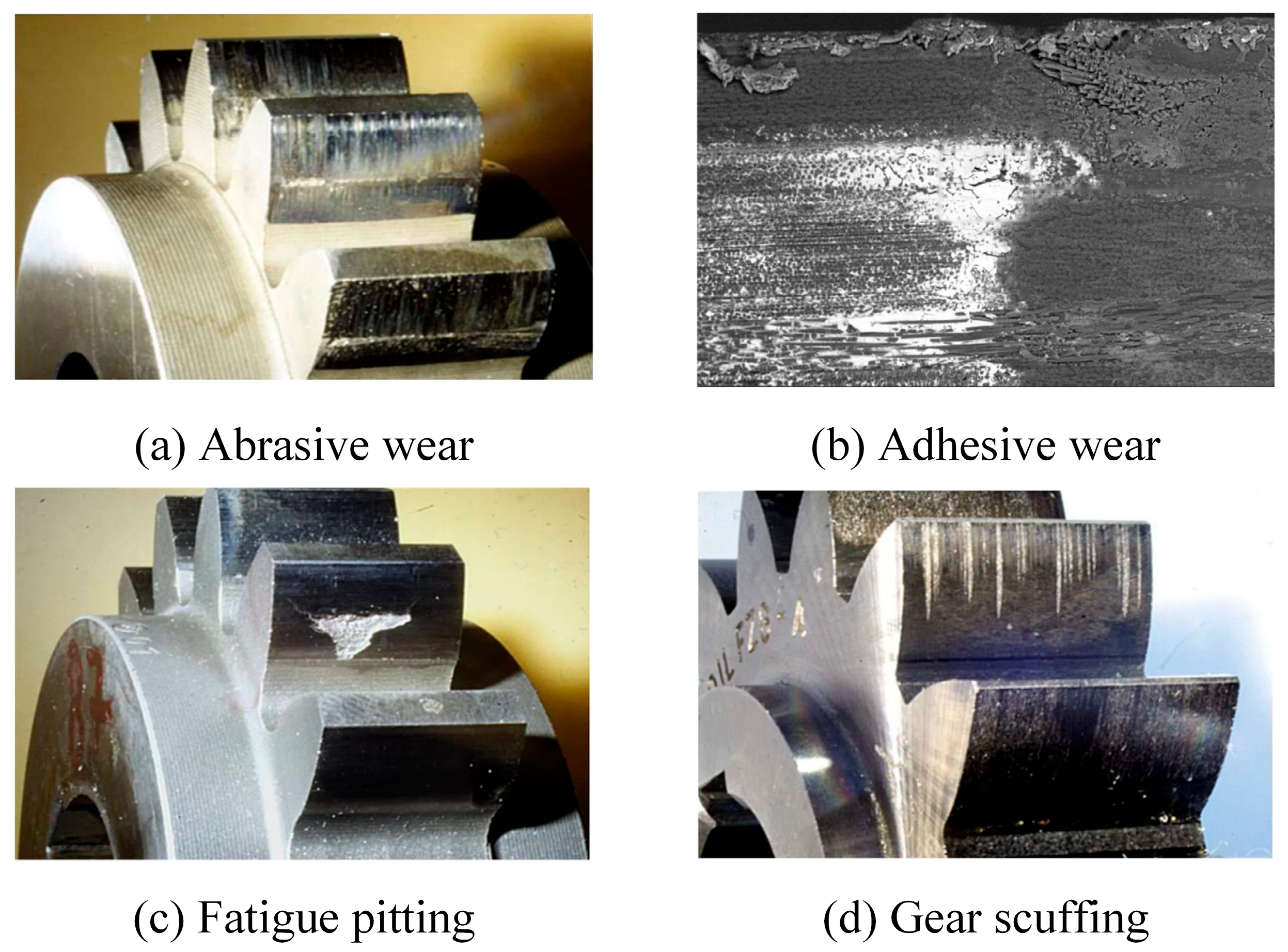
During repeated meshing, gears are subjected to cyclic contact stresses, rolling–sliding friction, and complex lubrication conditions, which may give rise to various tooth-surface damage modes. ISO 10825-1:2022 [2] and ANSI/AGMA 1010-F14 [3] provide systematic definitions and descriptions of the observable characteristics of gear tooth-surface damage. It should be noted that tooth-surface damage is a general term. Abrasive, adhesive, and corrosive wear mainly describe mechanisms involving gradual material removal, whereas pitting and micropitting are contact-fatigue damage modes. Scuffing generally represents severe adhesive failure that occurs under lubrication failure and high-temperature conditions [2,3,4,5]. Typical features of these damage modes are shown in Figure 1. Their initiation conditions, evolution rates, and effects on meshing performance differ substantially and are often coupled during actual service.
Abrasive wear refers to material removal caused by hard asperities or hard particles that cut, plough, or scratch mating tooth surfaces during sliding or rolling–sliding contact. In geared systems, abrasive action may originate from the counter-surface roughness itself or from solid contaminants suspended in the lubricant. Its severity depends not only on particle hardness, size, morphology, and concentration but also on the film thickness separating the mating surfaces. Hard particles larger than the lubricant-film thickness are more likely to enter the contact and produce direct scratching or grooving, whereas softer or deformable particles may generate milder polishing-like effects or become entrapped and fragmented. Therefore, lubricant cleanliness, particle characteristics, and lubrication conditions jointly influence the effective abrasive wear mechanism and should be considered when selecting or calibrating wear parameters for a specific gear lubricant system [8].
Corrosive wear is a process in which tooth-flank material chemically reacts with moisture, oxygen, lubricant degradation products, or other corrosive media, while the resulting reaction products are continuously removed by friction. This damage mode accompanies lubricant deterioration and may manifest as rusting, dark spots, pitting, or localized surface roughening.
Pitting and micropitting are both tooth-surface contact-fatigue damage modes. Pitting is generally caused by the propagation of surface or subsurface fatigue cracks induced by cyclic Hertzian contact stresses; visible material spalling pits form once the cracks coalesce or propagate through the surface. Severe pitting disrupts tooth-flank continuity and increases dynamic loading. Micropitting occurs on a smaller scale and is commonly characterized by a grey, dull appearance or densely distributed microscopic pits. Its formation is closely associated with asperity contact, low specific film thickness, and rolling contact fatigue.
Scuffing typically occurs under high-speed, heavy-load, insufficient lubrication, or excessive local temperature conditions. Under these conditions, the lubricant film ruptures and directly contacting asperities undergo intense adhesion and shearing, producing material tearing, transfer, and scuff marks extending along the sliding direction. Compared with mild adhesive wear, scuffing is more sudden and destructive and is often accompanied by a rapid friction-induced temperature rise and pronounced deterioration in transmission performance. Sagraloff et al. [6] experimentally investigated the scuffing and wear characteristics of an oil-free water-based lubricant for gear applications, demonstrating the practical relevance of lubricant formulation when evaluating lubricant-dependent surface damage in gear contacts. Other damage modes, including plastic deformation, indentation, and fracture, may also occur on tooth flanks; however, their governing mechanisms differ from the progressive material loss considered in this review and are therefore not the focus of the subsequent wear prediction discussion.
In summary, abrasive wear, mild adhesive wear, and corrosive wear are time-accumulated material removal processes, although their dominant controlling variables differ. Progressive abrasive wear is commonly described using Archard-type local material removal formulations coupled with contact pressure calculation, sliding distance evaluation, and iterative tooth-flank geometry updating [9,10,11]. Mild adhesive wear can be represented using modified Archard-type or mixed-lubrication formulations in which the direct-contact contribution, frictional conditions, and lubricant-film state affect the effective wear rate [12,13]. Corrosive wear requires additional consideration of lubricant degradation and chemical reaction conditions [14]. In contrast, pitting and micropitting are primarily evaluated using contact-fatigue or risk-based approaches, whereas scuffing is generally assessed using flash temperature or lubrication failure criteria [15,16]. Accordingly, Table 1 distinguishes the representative modeling routes of the different damage modes. This review focuses on progressive tooth-flank wear caused by continuous material removal and gradual tooth-profile evolution; the other damage modes are considered only where they affect or are affected by the evolution of the worn surface. Having defined the progressive wear addressed in this review, the following section summarizes the relevant prediction methods.

3. Research on Gear Wear Prediction

The Archard wear model, owing to its simple formulation and clear physical basis, is one of the fundamental models for describing material removal from contacting surfaces and has been widely applied to gear tooth-flank wear prediction. Its global form can be written as
d V d s = K F N H
where V is the wear volume, s is the sliding distance, FN is the normal load, H is the material hardness, and K is the wear coefficient. For gear contact calculations, a local differential form is commonly used:
d h = K H σ H t v s t d t
where d h is the local wear depth increment, σ H t is the time-varying contact stress, and v s t is the local sliding velocity. Therefore, the differences among gear wear prediction models mainly lie in how contact stress, sliding motion, wear coefficient, lubrication state, and tooth-flank geometry are determined and updated. The influence of tooth-flank geometry on lubrication and wear is transmitted through local curvature, contact area, entrainment velocity, sliding velocity, and contact pressure distribution. Along the line of action, the sliding velocity approaches zero near the pitch point and increases toward the tooth-root and tooth-tip regions; consequently, frictional heat generation and wear-driving conditions are spatially non-uniform. Variations in local curvature and contact pressure also modify the lubricant-film thickness and the probability of direct asperity contact. Under high-load or high-sliding conditions, the combined effects of the friction coefficient, local pressure, and sliding velocity may increase the flash temperature, which changes the local lubricant viscosity and the subsequent EHL or mixed-lubrication state [12,17]. Under lubricated conditions, the lubricant film alters the direct-contact contribution, interfacial friction, and temperature rise; consequently, the effective wear coefficient and contact quantity cannot be treated as fixed parameters. Depending on whether the lubrication state is calculated, existing studies can be classified as models that neglect lubrication effects and models that incorporate lubrication effects. The former provide the basis for tooth-flank geometry updating and wear distribution calculation, whereas the latter additionally consider the evolving interfacial state.

3.1. Gear Wear Prediction Without Considering Lubrication Effects

Early studies commonly coupled the Archard model with gear contact analysis under dry-contact conditions. Flodin and Andersson [9,10] were among the first to employ a Winkler elastic foundation model and a generalized Archard equation to simulate mild wear in spur gears, demonstrating that wear progressively modifies the tooth-flank pressure distribution. They subsequently extended this approach to helical gears and found that contact asymmetry across the face width may lead to more pronounced wear near the tooth-tip and tooth-root edges. Bajpai et al. [11] developed a finite element contact-wear iterative framework applicable to both spur and helical gears. Their experiments showed that the initial tooth-flank geometry, manufacturing deviations, and accuracy of contact pressure calculations all affect the reliability of wear predictions.
For complex tooth-flank geometries and spatial meshing problems, research has focused on contact area reconstruction and computational efficiency. Park and Kahraman [18] combined the Archard model with a finite element contact model for hypoid gears to predict their wear distribution. Park et al. [19,20] subsequently reduced the computational cost of long-term simulations through semi-analytical contact models, surface interpolation, and single-meshing-cycle calculations. These studies indicate that, for complex gears, geometric updating, contact area reconstruction, and sliding distance calculation are not independent procedures; instead, they are fundamental determinants of the accuracy of wear distribution prediction.
As models have progressively approached actual service conditions, they have incorporated factors such as surface topography, edge contact, and assembly errors. Chen and Ji [21] developed a load distribution and wear prediction model considering tooth-profile edge contact and demonstrated the coupling between load sharing and wear depth. Wang et al. [22] established a rough-surface contact model using piecewise linear interpolation and found that surface roughness causes local fluctuations in contact pressure, whereas tooth-profile errors have a more direct effect on the accumulated wear depth. Sun et al. [23] and Jangra et al. [24] respectively investigated the effects of positional tolerances, radial misalignment, axial misalignment, and combined misalignment on the contact path, contact pressure, and wear distribution. Both studies indicated that assembly deviations may induce edge contact and aggravate localized wear. Compared with ideal meshing models, these studies better explain why localized wear often first occurs in regions with deteriorated contact conditions.
Building on quasi-static models, some studies have introduced dynamic meshing forces. He et al. [25] developed a finite element method for calculating tooth-flank wear depth while accounting for dynamic meshing forces. The calculation of the wear coefficient, dynamic contact stress, and relative sliding distance was validated using pin-on-disc tests and a dynamic model. This study indicates that under high-speed, heavy-load, or near-resonance conditions, replacing the actual dynamic meshing force with a static or quasi-static load may not accurately represent the evolution of localized wear.
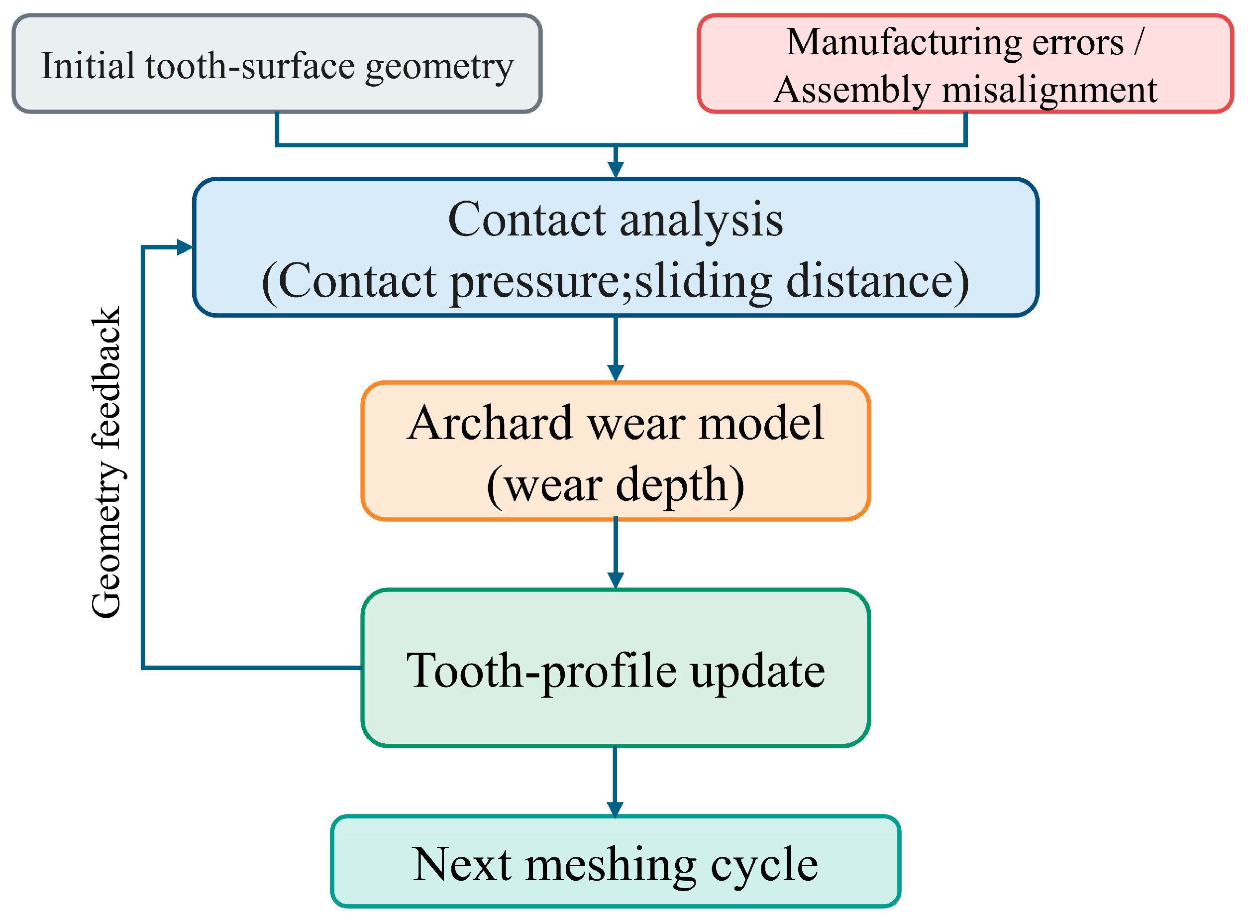
The reviewed models without lubrication treatment can be divided into three representative categories. First, quasi-static Archard contact models calculate local wear increments from contact pressure and sliding distance and are suitable for identifying the influence of tooth geometry and load distribution on long-term wear patterns. Second, finite element and semi-analytical contact-wear models determine the local pressure field from tooth-flank geometry, contact area, curvature, and possible edge contact before updating the worn surface; these approaches are particularly useful for complex gear geometries and non-uniform wear. Third, dynamic load wear models replace the prescribed or quasi-static load with a time-varying dynamic mesh force, allowing contact stress and sliding motion to change with operating speed, torque, mesh stiffness, damping, and resonance conditions. The first two categories are computationally efficient for quasi-static wear distribution analysis, whereas the third category is more appropriate when dynamic excitation significantly affects the local contact condition. Although these models differ in their contact solution methods, loading schemes, and geometric representations, their computational procedures generally consist of contact analysis, local wear calculation, and tooth-flank geometry updating. The basic iterative framework for wear prediction without lubrication modeling is illustrated in Figure 2.
Models that neglect lubrication effects offer a clear computational framework and readily accommodate tooth-flank geometry and assembly-related factors, making them suitable for analyzing how variations in contact conditions affect wear distribution. However, such models typically treat the wear coefficient as an empirical parameter and cannot adequately represent the effects of lubricant-film load-carrying capacity, asperity contact, and interfacial temperature rise on material removal. As gear speed and power density increase, dry-contact assumptions or equivalent contact parameters alone are no longer sufficient to describe actual wear behavior. It is therefore necessary to further consider the evolution of lubrication conditions.

3.2. Gear Wear Prediction Considering Lubrication Effects

Wear prediction incorporating lubrication effects is generally based on mixed elastohydrodynamic lubrication (EHL) or thermal EHL theory. The effects of lubrication conditions on wear rate are characterized through oil film pressure and thickness, the proportion of asperity contact, and frictional behavior. Wu and Cheng [12] were among the first to combine gear dynamics, rough-surface contact, and partial EHL to derive the equivalent wear rate and wear profile of spur gears along the line of action. They reported that the pinion root and gear tip are more susceptible to wear because of the greater sliding in these regions. Osman and Velex [17] introduced lubrication conditions into wear simulations of wide-face spur and helical gears, further demonstrating that wear may vary not only along the line of action but also non-uniformly across the face width, thereby exerting different effects on the dynamic responses of different gear types.
Under lubricated conditions, determining the wear coefficient and the degree of direct surface interaction is a prerequisite for accurate prediction. The lubrication state is commonly characterized by the specific film thickness:
λ = h m i n R q 1 2 + R q 2 2
where h m i n is the minimum lubricant-film thickness and R q 1 and R q 2 are the root-mean-square roughness values of the two contacting tooth flanks. For gear contacts, the roughness values should represent the actual topography at the relevant meshing position and measurement scale. Roughness in the tooth-profile direction is directly associated with rolling–sliding contact along the line of action, whereas roughness and waviness along the face-width direction influence transverse load distribution and the tendency for edge contact. In addition, the roughness state may differ between the tooth-root, pitch-point, and tooth-tip regions because the local sliding, pressure, and surface evolution conditions are not uniform [22,26]. A lower λ generally indicates a greater contribution of asperity contact and a higher sensitivity of wear to load, temperature, lubricant viscosity, and surface roughness. In mixed-lubrication models, the total normal load is shared by the lubricant film and asperities:
W = W f + W a
where W f and W a denote the film-supported and asperity-supported loads, respectively. The wear-driving quantity should therefore be associated with the direct-contact contribution rather than the total applied load alone. Janakiraman et al. [27] analyzed the effects of load, speed, temperature, surface roughness, and the pressure–viscosity coefficient on the wear coefficient through twin-disc tests. They found that wear is particularly sensitive to the pressure–viscosity coefficient and surface roughness. Masjedi and Khonsari [28] used a mixed thermal EHL model to predict the steady-state wear rate of spur gears, showing that inadequate lubricant supply reduces the specific film thickness, increases the asperity load-sharing ratio, and produces a pronounced nonlinear wear rate distribution along the line of action. These results indicate that the wear coefficient is governed by the combined effects of contact conditions and lubricant-film behavior. Therefore, although specific film thickness reflects the lubrication condition, it cannot independently serve as a measure of gear antiwear performance.
Specific film thickness is also closely related to surface-fatigue damage. A reduction in film thickness or an increase in composite roughness raises the probability of asperity interaction and may promote the surface distress associated with micropitting. The micropitting load capacity of cylindrical spur and helical gears is also assessed through the micropitting safety factor procedure specified in ISO/TR 15144-2, which provides an engineering framework for relating contact conditions and lubrication-related parameters to micropitting risk [29]. Because lubricant viscosity is temperature-dependent, variations in bulk oil and interfacial temperatures modify the EHL or thermal EHL solution, including film thickness, pressure distribution, frictional heating, and asperity load sharing. Micropitting is therefore associated with the coupled effects of low specific film thickness, rough-surface interaction, cyclic contact stress, lubricant formulation, and operating temperature rather than with progressive material removal alone. Sagraloff et al. [30] further demonstrated the practical relevance of lubricant properties, operating temperature, material, geometry, and grinding condition for micropitting load capacity. Brummer et al. [31] investigated the influence of synthetic lubricants on the pitting load-carrying capacity of cylindrical gears. Although pitting and micropitting are treated in this review as lubrication-dependent surface-fatigue modes rather than as progressive material removal processes, this work further supports the need to consider lubricant formulation when discussing the surface-durability context of gear contacts. In addition, Wainwright et al. [32] showed that micropitting and macropitting occupy different contact-condition domains, confirming that lubrication state and surface condition govern the transition between competing fatigue damage modes.
Regarding the coupled evolution of wear and other surface damage modes, Morales-Espejel et al. [16] developed a model incorporating mixed lubrication, mild wear, and micropitting. They indicated that appropriate running-in can remove some asperities and reduce the subsequent risk of fatigue damage, whereas excessive wear continuously degrades tooth-flank geometry. Wang et al. [13] developed a mixed EHL adhesive wear model for heavily loaded helical gears and modified the Archard model using the film defect ratio. Their results showed that the predicted wear depth under mixed lubrication is lower than that under dry-contact conditions. Nevertheless, increased surface roughness and input torque still aggravate wear, whereas a higher rotational speed promotes lubricant-film formation. Collectively, these studies demonstrate that lubrication and wear do not exhibit a simple unidirectional inhibitory relationship; their interaction depends on surface conditions, transmitted loads, and operating conditions.
In recent years, research has further extended to start–stop processes, oil–air lubrication, lubricant degradation, and special gear configurations. Xiao et al. [33] investigated the thermal wear behavior of double-helical gears under steady-state full-film lubrication and mixed lubrication during start–stop operation. They found that surface roughness during the start–stop stage has a particularly strong influence on the asperity load-sharing ratio and wear depth. Zhao et al. [26,34] examined the effects of different lubricants on spur gear wear under oil–air mixed lubrication and showed that increasing lubricant viscosity reduces the proportion of direct asperity contact. Their subsequent work further indicated that surface skewness and kurtosis alter the number of asperities, thereby affecting the friction coefficient, flash temperature, and accumulated wear. Su et al. [14] incorporated lubricant water content, viscosity variation, and corrosion reactions into a planetary gearbox wear model, demonstrating that lubricant degradation not only affects lubricant-film load-carrying capacity but may also alter the lubrication regime and the risk of corrosive wear.
The initial surface state established by manufacturing and finishing processes affects the subsequent lubrication and wear evolution. Grinding marks, roughness amplitude, waviness, and directional texture influence the initial film thickness ratio and asperity contact condition. Surface-finishing processes such as superfinishing modify these initial topographic features and can alter the susceptibility of gear contacts to micropitting and progressive wear. Their influence depends on the combined effects of surface condition, material properties, lubricant chemistry, load, speed, and contact-fatigue behavior [16,35].
The bidirectional interaction between lubrication conditions and wear morphology has also begun to attract attention. Yin et al. [36] investigated the feedback effects of wear in double-involute gears on lubrication performance, showing that accumulated wear alters the radius of curvature, entrainment velocity, slide-to-roll ratio, and sliding distance. These changes reduce specific film thickness while increasing the asperity load-sharing ratio and friction coefficient. Dong et al. [37] further developed a coupled model for MoS2 solid-lubricant-coated planetary gears that incorporates thermal deformation, wear, coating behavior, and dynamics. Their results revealed the competing effects of thermal deformation and wear on contact pressure and dynamic transmission error at different service stages. Compared with models that calculate lubrication conditions solely from the initial tooth-flank geometry, these studies regard wear-induced geometric changes as important variables governing subsequent interfacial behavior.
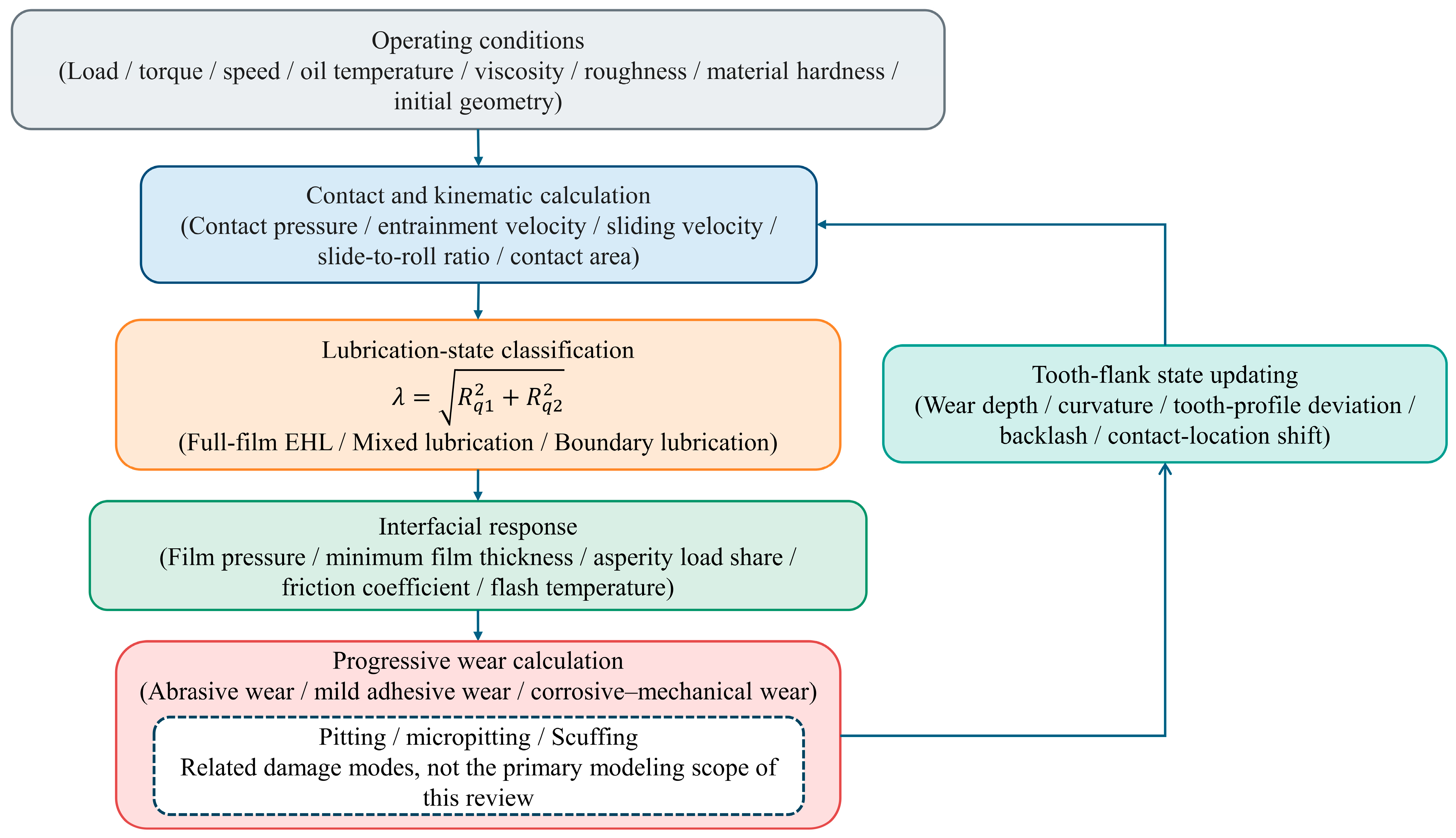
The above studies indicate that wear prediction under lubricated conditions should be regarded as a closed-loop process rather than a one-way calculation. Operating conditions determine the contact and lubrication states; these states govern film formation, asperity contact, friction, temperature rise, and local material removal; and the resulting tooth-flank evolution subsequently changes the geometry and surface variables used in the next calculation step. The resulting lubrication wear feedback framework is summarized in Figure 3.
Table 2 compares the reviewed modeling approaches in terms of their core quantitative treatment, key input variables, main outputs, engineering applicability, and limitations. Although all approaches are based on contact-driven material removal, they differ substantially in the treatment of contact load, sliding motion, wear coefficient, lubrication state, temperature, dynamic excitation, and tooth-flank updating. This comparison highlights why a model suitable for quasi-static wear distribution analysis may not be sufficient for high-speed, lubrication-sensitive, or long-term tribodynamic applications.
As shown in Table 2, existing studies have separately addressed complex contact geometry, lubrication conditions, assembly errors, and dynamic meshing forces. However, most models do not update these factors simultaneously. This limitation warrants further investigation from the perspective of bidirectional coupling between gear system dynamics and tribology.

4. Gear Tribodynamics, Dynamic Effects of Tooth-Flank Wear, and Their Influencing Factors

4.1. Research on Gear Tribodynamics

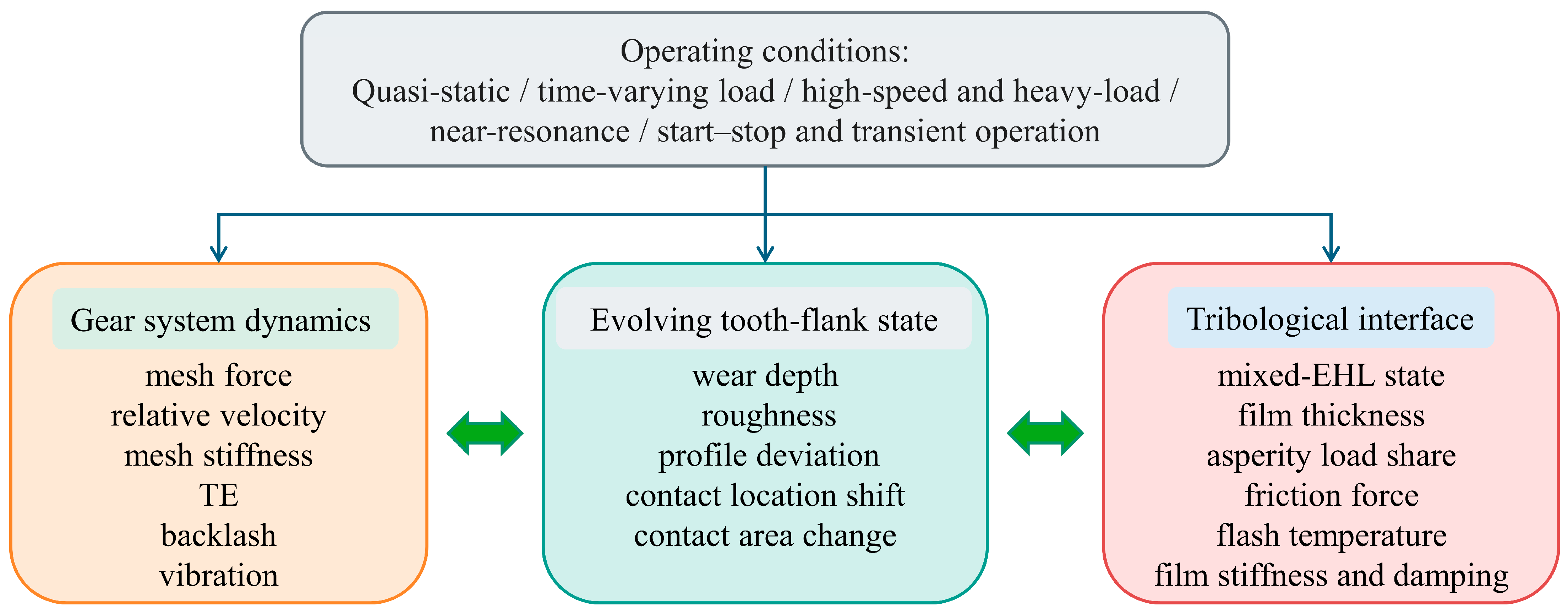
To characterize variations in lubrication conditions and friction forces under dynamic meshing, a gear tribodynamic model must establish a bidirectional relationship among gear system dynamics, interfacial tribological conditions, and the evolving tooth-flank state. The dynamic model provides the time-varying mesh force, relative velocity, and motion parameters. The tribological model feeds back friction force, lubricant-film stiffness, damping, and thermal quantities. Meanwhile, progressive wear changes surface roughness, tooth-profile geometry, contact location, backlash, and contact conditions, thereby influencing the subsequent dynamic and tribological responses. The resulting coupling under quasi-static, time-varying load, high-speed, near-resonance, and transient operating conditions is illustrated in Figure 4.
Within this framework, Li and Kahraman [38] were among the first to establish a bidirectionally coupled mixed EHL dynamic model for spur gears. The lubrication model calculated time-varying friction force, friction torque, and lubricant-film damping, whereas the dynamic model provided dynamic tooth-flank loads and surface velocities. Their results showed that surface roughness, lubricant temperature, input torque, and rotational speed can all alter the tribodynamic response of gear systems.
Subsequent studies extended isothermal contact analyses to incorporate thermal effects and complex motion conditions. Li [39] coupled thermal mixed EHL with a six-degree-of-freedom gear dynamic model to investigate mechanical power loss and reported substantial discrepancies between quasi-static and thermo-tribodynamic results near resonance. Ouyang et al. [40] developed a finite line-contact mixed EHL dynamic model for a special spur gear with axial motion, demonstrating that the lubricant-film thickness, asperity load-sharing ratio, and friction coefficient under dynamic conditions differ from their quasi-static counterparts. These studies indicate that dynamic motion affects not only meshing forces but also the thermal and interfacial states governing friction and power loss.
Mechanical power loss is coupled to the tribological state through frictional heat generation. Variations in bulk oil and interfacial temperatures modify temperature-dependent lubricant viscosity, film thickness, and asperity load sharing, thereby affecting the local conditions governing progressive wear. The magnitude of this thermal feedback depends on gear geometry, transmitted load, speed, lubricant formulation, and thermal boundary conditions [39]. Michaelis et al. [41] investigated the influence factors governing gearbox power loss, providing an engineering context for considering operating and lubricant-related variables in the thermal feedback between power loss, temperature, lubrication conditions, and progressive wear.
Concerning mesh stiffness, backlash, and nonlinear response, Li et al. [42] developed a spur gear tribodynamic model incorporating lubricant-film stiffness and lubrication-related backlash. They showed that lubrication conditions can suppress tooth separation and reduce vibration in resonance regions. Hu et al. [43] developed a nonlinear dynamic model for loss-of-lubrication conditions that incorporated a time-varying friction coefficient, temperature rise, and tooth-flank wear. Their experiments validated the effects of temperature rise and wear on the nonlinear response of high-speed gears. Wang et al. [44] integrated transient mixed lubrication, time-varying mesh stiffness, backlash, and dynamic friction into a gear tribodynamic model. Wu et al. [45] reported that dynamic loading induces substantial fluctuations in the friction coefficient, lubricant-film pressure, and film thickness in high-speed, heavily loaded helical gears. These studies demonstrate that friction force is not a constant applied load but an interfacial response jointly governed by dynamic loading, lubricant-film condition, tooth-flank velocity, and temperature.
In summary, under quasi-static or low-speed conditions, the contact pressure distribution, sliding motion, and lubricant-film state are mainly governed by the meshing position and applied load [17]. Under time-varying loading, dynamic mesh force and relative motion induce periodic changes in contact stress, film thickness, friction force, and asperity load sharing [25,38]. Under high-speed, heavy-load, or near-resonance conditions, dynamic amplification and frictional heating may produce responses that differ substantially from quasi-static predictions, particularly in terms of flash temperature, power loss, and lubricant-film behavior [39,40,45]. During start–stop or other transient processes, rapid variations in speed and film formation increase the sensitivity of wear to surface roughness and direct asperity contact [33]. However, most existing tribodynamic models still treat surface conditions and frictional properties as prescribed inputs, making it difficult to evaluate their long-term coupled evolution with progressive wear. Moreover, the manner in which wear-induced changes in tooth-flank topography feed back into mesh stiffness, transmission error, and dynamic meshing forces still requires analysis in conjunction with the wear evolution process.

4.2. Effects of Tooth-Flank Wear on Mesh Stiffness, Transmission Error, and Dynamic Response

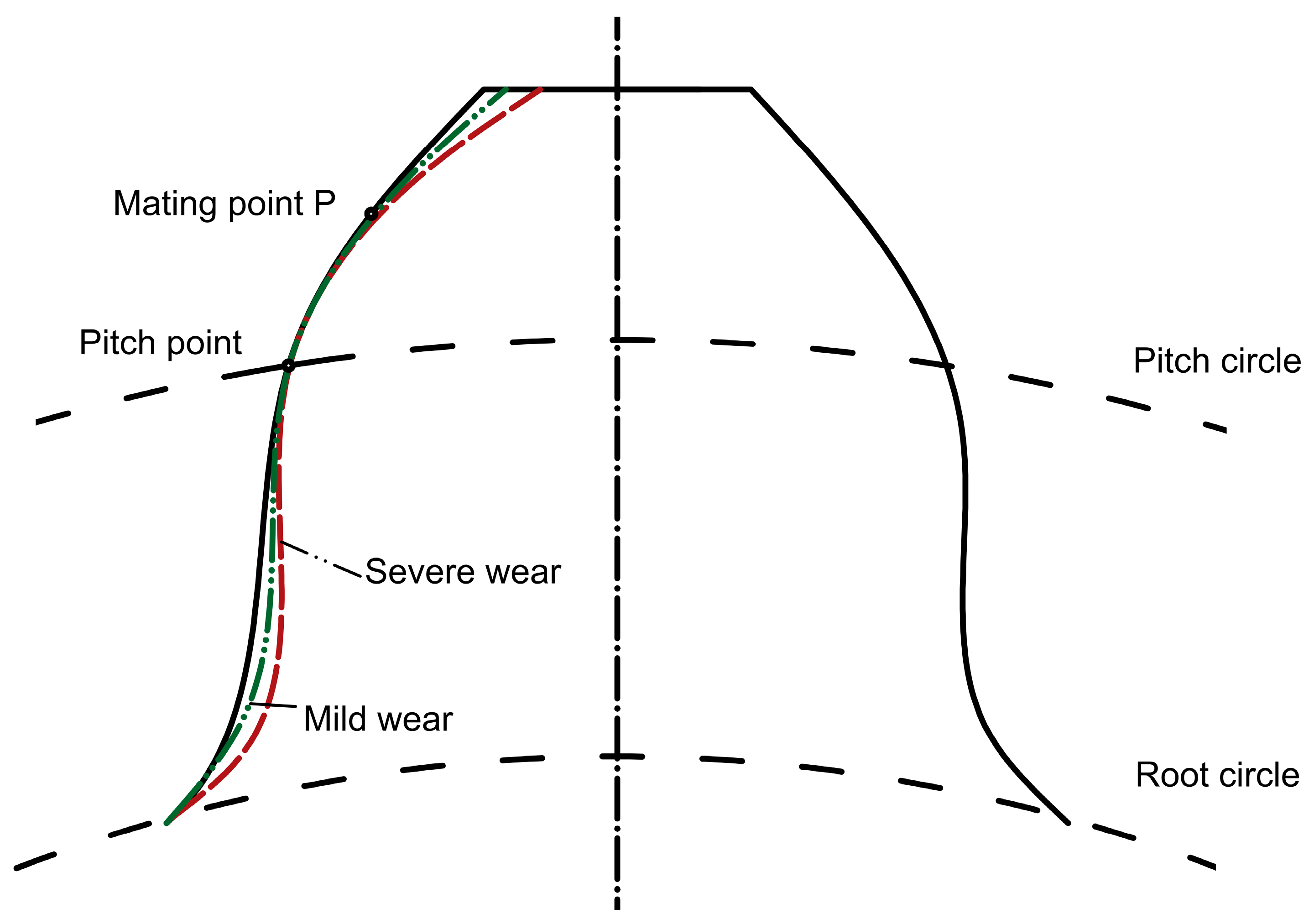
Tooth-flank wear alters tooth-profile geometry (as schematically illustrated in Figure 5), contact location, and backlash, thereby affecting time-varying mesh stiffness, transmission error, and dynamic meshing forces and degrading the dynamic performance of gear systems. Elastic tooth deflection provides an intermediate mechanical link between local wear and system-level dynamic response. Under load, tooth deflection changes the actual contact interval, contact ratio, and load sharing among simultaneously meshing tooth pairs; these changes determine the time-varying mesh stiffness and transmission error.
For a loaded gear mesh, the load carried by the engaged tooth pairs is governed by contact compatibility. If n t tooth pairs are potentially in contact, the total normal force can be expressed as
F N t = ∑ j = 1 n t F j t  
F j t = k j t [ δ t − e j t ] +
where F j is the load carried by tooth pair j ,   k j is its local normal stiffness, δ is the relative approach of the two gears, e j represents the local geometric deviation or separation associated with tooth pair j , and x + = max x , 0 ensures that only closed contacts transmit load. The effective mesh stiffness is therefore determined by the stiffnesses of the tooth pairs that are actually engaged,
K m t = ∂ F N ∂ δ ≈ ∑ j ∈ C t k j t
where C t denotes the set of tooth pairs in contact. The compliance of an individual tooth pair includes the Hertzian contact, bending, shear, and foundation contributions of the pinion and gear. Thus, 1 / k j may be represented as the sum of the corresponding component compliances.
For an idealized mesh with linear compliance and a fixed contact configuration, the stiffness of an individual tooth pair may exhibit only limited load dependence. In an actual loaded gear mesh, however, increasing transmitted load changes tooth elastic deflection, the effective contact interval, the number and extent of simultaneously engaged contacts, and the load distribution between tooth pairs. These load-dependent changes modify the effective time-varying mesh stiffness, transmission error, and dynamic mesh force. Progressive wear further changes e j through local material removal, profile modification, backlash variation, and contact position shift. Consequently, the load-sharing state and mesh stiffness should be updated together with the evolving tooth-flank geometry in long-term wear dynamic analyses [46,47,48,49,50,51].
As progressive wear modifies tooth geometry, backlash, and contact location, the local compliance and the resulting dynamic response also evolve. Wear-induced geometric changes and elastic deformation should therefore be updated consistently in coupled analyses [46,47,48]. Ding and Kahraman [46] coupled a nonlinear gear dynamic model with a surface wear model and revealed a bidirectional interaction between wear and dynamic response. Under certain operating conditions, initial mild wear may reduce tooth separation and nonlinear jump phenomena; however, as wear becomes more severe, the nonlinear response and vibration characteristics of the system deteriorate again. Liu et al. [47] further investigated spur gears using a translational–torsional coupled dynamic model and a quasi-static wear model. They found that accumulated wear alters mesh stiffness and transmission error, while dynamic operating conditions, in turn, affect wear depth and its distribution.
Figure 5. Variations in the tooth profile with gear wear. Adapted from Ref. [52].
Lubricants 14 00334 g005
For planetary gear systems, Shen et al. [48] analyzed the effect of tooth-flank wear on time-varying mesh stiffness using the potential energy method and the Archard equation and found that the reduction in stiffness depends on wear depth. Shen et al. [52] subsequently introduced wear-induced variations in time-varying mesh stiffness, no-load static transmission error, and backlash into a planetary gear dynamic model as internal excitations, demonstrating that different meshing pairs exhibit different dynamic responses to wear. For external spur gears, Shen et al. [53] established a new meshing relationship model for worn gears. Their experiments indicated that wear generally does not alter the fundamental structure of the frequency spectrum but changes the amplitudes of the meshing frequency and sideband components.
Some studies have further considered wear distribution, temperature, and coupled faults. Geng et al. [54] investigated changes in time-varying stiffness and backlash caused by non-uniform and uniform wear and found that wear severity and operating time substantially alter bifurcation characteristics, period-doubling motions, and chaotic responses. Zhang et al. [55] incorporated tooth-flank contact temperature and wear faults into a high-speed-stage model of a wind turbine gearbox. They reported that temperature rise reduces mesh stiffness and changes the conditions under which the system enters bifurcation and chaotic states. Cao et al. [56] examined an evolving coupled crack–wear fault and demonstrated that wear cannot be neglected during gear transmission degradation. Liu et al. [57] analyzed the dynamic characteristics of a gear–rotor system under the combined effects of eccentricity and wear. Compared with models considering wear as an isolated fault, these studies more effectively represent the complexity arising from multiple interacting factors in actual transmission systems.
Under lubricated conditions, the effects of wear on dynamic response are also governed by changes in interfacial conditions. Zhao et al. [58] integrated actual machined tooth flanks, mixed lubrication sliding wear, and gear dynamics. They found that the wear depth under mixed lubrication is lower than that under dry-contact conditions, although tooth-flank wear still increases the relative vibration displacement across different frequency bands. Li et al. [59] developed a deterministic tooth-flank degradation model linking rough-surface evolution, contact stiffness, time-varying mesh stiffness, and a four-degree-of-freedom dynamic model, which was validated through tooth-profile evolution and vibration experiments. Feng et al. [60] proposed a digital twin method for gear wear based on transmission error updating to monitor the spatial evolution of non-uniform wear. Xiong et al. [61] further developed a coupled wear dynamic model incorporating surface topography, lubrication conditions, and dynamic loading. Their results showed that wear modifies surface topography and lubrication conditions while intensifying fluctuations in dynamic load, friction force, and the mesh transition region. Conversely, the evolution of interfacial properties affects the subsequent wear rate and system vibration response.
Wear-dynamic coupling follows a closed causal sequence. Progressive material removal changes tooth-profile geometry, local curvature, backlash, and the contact interval. These geometric changes redistribute the load among tooth pairs and modify the time-varying mesh stiffness, which alters transmission error, dynamic meshing force, and vibration response. The updated dynamic meshing force subsequently changes the local contact pressure, sliding condition, lubrication state, and material removal rate in the following wear-update step. Therefore, tooth-flank wear does not merely cause a monotonic reduction in mesh stiffness; its dynamic effects are stage-dependent and operating-condition-dependent. Existing studies have separately developed tribodynamic models, dynamic wear prediction models, and wear-fault dynamic models. However, closed-loop models capable of simultaneously describing surface topography evolution, lubrication conditions, frictional behavior, dynamic meshing forces, and long-term wear remain limited. Moreover, assembly errors and parameter variability alter the contact conditions and loading boundaries governing this feedback process. The following section therefore discusses the effects of these factors.

4.3. Effects of Assembly Errors and Parameter Uncertainties on Gear Meshing and Dynamic Characteristics

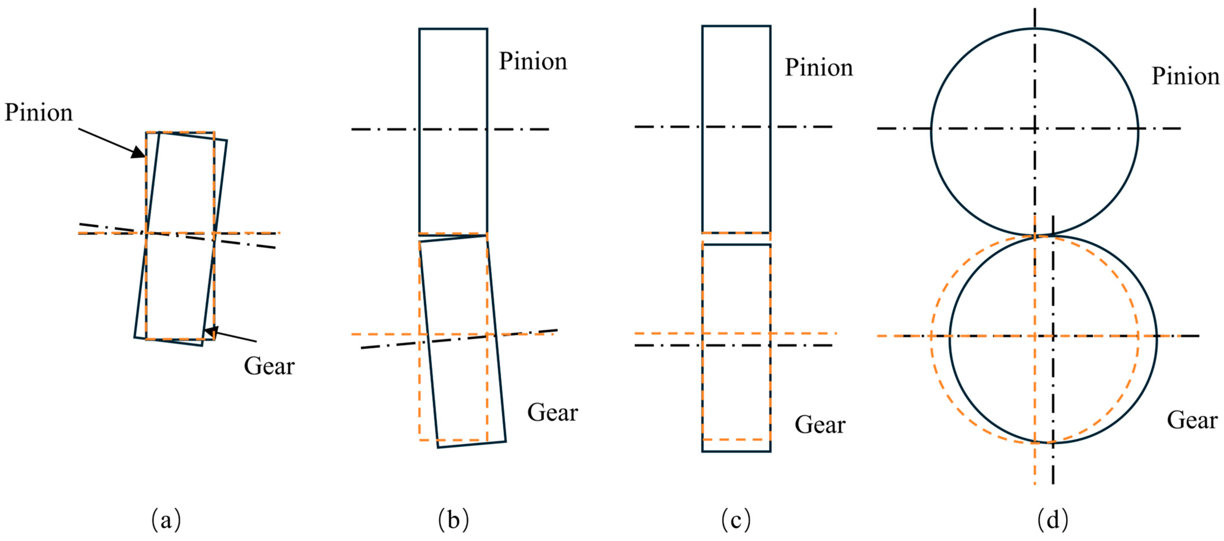
Actual gear transmission systems inevitably exhibit assembly errors, such as center-distance deviations, gear eccentricity, and shaft misalignment, as illustrated in Figure 6, where the yellow dashed lines indicate the ideal gear positions. These errors alter the actual meshing position, contact region, and tooth-flank separation distance, thereby affecting time-varying mesh stiffness, load distribution, transmission error, and system dynamic response. Compared with models that assume ideal gear installation, those incorporating actual assembly conditions can describe gear meshing relationships and internal excitations more accurately.
Luo et al. [63] developed a meshing kinematics model capable of determining the actual tooth-flank contact position for spur gears with center-distance variations. They investigated the effects of constant and time-varying center-distance deviations on time-varying mesh stiffness. The results showed that center-distance variations alter the contact ratio, mesh stiffness amplitude, and frequency components. When the center distance varies with time, both amplitude and frequency modulation occur in the mesh stiffness. The study further indicated that when multiple faults coexist, changes in mesh stiffness cannot be obtained by simply superimposing the effects of individual faults, demonstrating nonlinear coupling between assembly errors and other faults.
Cao et al. [64] further investigated the effects of gear eccentricity errors on the dynamic performance of planetary gear transmissions by incorporating eccentricity-induced variations in center distance and actual meshing position into a planetary gear dynamic model. The results showed that eccentricity errors cause periodic variations in the amplitude and frequency of mesh stiffness, resulting in complex modulation of the dynamic response. As eccentricity increases, dynamic load distribution and transmission performance deteriorate. For planet gear eccentricity, the assembly-phase relationship also affects load distribution, and an appropriate assembly configuration can improve dynamic load sharing under certain conditions.
For position errors in planetary gears, Xu et al. [65] developed a dynamic model that simultaneously considered the actual meshing positions of external and internal gear pairs, tooth-pair separation distances, and edge contact. They found that position errors alter mesh stiffness and load distribution. Particularly under heavy loads, neglecting the actual meshing position and tooth-pair separation distance may cause substantial errors in load-sharing predictions. Position errors do not necessarily degrade performance under all operating conditions; within a specific range, some position errors may improve load distribution, although this effect is strongly operating-condition-dependent.
In addition to assembly errors, manufacturing errors, material properties, mesh stiffness, and transmission errors are also uncertain. Wei et al. [66] employed a Chebyshev interval method to analyze the effects of uncertain mesh stiffness, transmission error, mesh damping, shaft damping, rotational inertia, and shaft torsional stiffness on the torsional dynamic response of a wind turbine gear transmission. They found that the response interval of the dynamic meshing force expands considerably when multiple uncertain parameters act simultaneously, with uncertain transmission error and drive-shaft torsional stiffness having particularly pronounced effects. Compared with Monte Carlo methods, interval methods do not require large numbers of random samples and therefore incur lower computational costs.
Wei et al. [67] subsequently treated mesh stiffness, bearing stiffness, and mass parameters as bounded uncertain variables and conducted theoretical and experimental investigations on a single-stage spur gear system. The results showed that the system response interval gradually expands as the range of parameter deviations increases. Uncertain mesh stiffness mainly affects the response below the resonance frequency, whereas uncertain mass has a more pronounced effect above resonance. Experimental validation confirmed the effectiveness of the interval dynamic analysis method, demonstrating that parameter uncertainty directly affects predictions of the resonance interval and amplitude–frequency response.
In recent years, uncertainty studies have been extended to shaft misalignment, lubrication parameters, and modification parameters. Hu et al. [62] represented shaft misalignment as an interval uncertain parameter and developed a multidimensional nonlinear interval dynamic model, showing that different types of misalignment exert distinct effects on dynamic performance. Chen et al. [68] investigated the effects of lubricant viscosity and lubrication-induced backlash variations on the deterministic and uncertain dynamic performance of high-precision spur gears. They found that increasing lubricant viscosity generally reduces backlash-induced dynamic transmission error and off-line-of-action vibration, although the magnitude of this effect depends on torque, rotational speed, and surface roughness.
Jiang et al. [69] developed a gear tribodynamic model incorporating tooth-profile modification and correlated parameter uncertainties. A Chebyshev subinterval decomposition method was used to calculate the response intervals of modified gears under correlated uncertainty. The results showed that uncertainties in lubricant viscosity and modification parameters affect torsional and translational vibrations, dynamic transmission error, contact pressure, and contact-fatigue life. Excessive modification amount, modification length, or modification power exponent, as well as increased uncertainty in these parameters, may substantially broaden the system response intervals. Chen et al. [70] further considered the correlated uncertainties between the lubricant pressure–viscosity coefficient and reference shear stress, showing that neglecting correlations among lubrication parameters may bias the estimated uncertainty intervals of dynamic response, flash temperature, and fatigue life.
Regarding stochastic uncertainty modeling, Chen et al. [71] treated input speed as a random variable following a probability distribution and applied polynomial chaos theory to investigate the influence of stochastic speed on mixed EHL performance. The results showed that the probability density function of the minimum film thickness varies periodically during meshing, while film thickness uncertainty is substantially amplified at positions where the dynamic meshing force increases abruptly. Jiang et al. [72] proposed an interval process analysis method combining Karhunen–Loève expansion with Chebyshev subinterval decomposition for uncertain time-varying loads. This method predicts the dynamic and tribological responses of gear systems when insufficient statistical information is available.
Overall, studies of assembly errors have revealed the effects of center-distance deviations, eccentricity, misalignment, and position errors on actual meshing positions, contact conditions, mesh stiffness, and load distribution. Uncertainty studies have further characterized the effects of variability in manufacturing errors, lubrication parameters, modification parameters, and dynamic loads on system response intervals and reliability. Existing research has progressed from deterministic error analysis to interval analysis, stochastic analysis, and correlated uncertainty propagation. However, most studies focus on healthy gears or prescribed wear states and have not adequately explained how assembly errors and multiple sources of uncertainty influence the long-term evolution of tooth-flank wear. These factors should therefore not be treated merely as additional disturbances in the dynamic analysis of healthy gears but as critical conditions governing wear trajectories, life prediction intervals, and the effectiveness of gear modification. Whereas assembly errors and parameter uncertainties are constraints that cannot be completely avoided during service, gear modification provides an active design approach for regulating contact conditions and dynamic excitation.

5. Effects of Gear Modification on the Dynamic Characteristics of Transmission Systems

Unlike unavoidable passive factors such as assembly errors and parameter variability, gear modification is an active design approach for regulating contact conditions and dynamic excitation. Its effectiveness depends not only on the modification parameters themselves but also on the actual load, assembly conditions, and stage of service.

5.1. Effects of Gear Modification on Mesh Stiffness, Load Distribution, and Transmission Error

Gear modification optimizes tooth-profile and lead geometries to compensate for elastic deformation, manufacturing errors, assembly errors, and load-induced local contact deviations, thereby regulating mesh stiffness, load distribution, and transmission error. The effects of a modification strategy depend on its geometric form, modification amount, modification length, transmitted load, and assembly condition. To clearly illustrate the effects of modification strategies on meshing behavior and progressive tooth-flank wear, we summarize them in Table 3.
Early studies mainly focused on the effects of tooth-profile modification on the dynamic loads and transmission errors of spur gears. Lee et al. [73] investigated variations in dynamic tooth loads and stresses in high-contact-ratio spur gears subjected to linear profile modification under different loads and showed that modification effectiveness is closely related to the load level and contact ratio. Lin et al. [74] compared the effects of linear and parabolic profile modifications on the dynamic loads of spur gears and found that appropriate profile modification reduces meshing impacts and dynamic loads. Kahraman and Blankenship [75] experimentally demonstrated that appropriate involute tip relief reduces dynamic transmission error.
Subsequent studies further examined the effects of modification on time-varying mesh stiffness, load distribution, and static transmission error. Velex et al. [76] presented analytical transmission error results for narrow-face spur and helical gears with different profile modifications, demonstrating that modification alters the effective contact interval and transmission error distribution. Ma et al. [49] proposed an analytical method for calculating the time-varying mesh stiffness of spur gears with tip relief. By modifying the tooth-contact, bending, and foundation deformation formulations, they improved the accuracy of mesh stiffness calculations for modified gears. These studies advanced gear modification from a purely geometric correction to an important design variable governing internal meshing excitation.
For different modification forms and optimization objectives, Ghosh and Chakraborty [77] investigated optimal tooth-profile modification curves for spur gears with the aim of reducing vibration and noise. They examined the effects of modification curve shape, modification amount, and modification length on dynamic response. Pleguezuelos et al. [78] investigated the use of symmetric profile modification to control the transmission error of high-contact-ratio spur gears, showing that modification parameters affect the transition between single- and double-tooth-pair contact intervals. Bruyère and Velex [79] subsequently developed performance diagrams for determining the optimal profile and lead modification parameters of spur and helical gears, enabling rapid evaluation of transmission error under different modification parameters. Compared with early studies that focused solely on reducing peak transmission error, modification optimization has progressively evolved toward the simultaneous consideration of multiple meshing performance criteria.
For off-design loading conditions, Pleguezuelos et al. [50] developed analytical models of mesh stiffness, load sharing, and transmission error for modified spur gears. They demonstrated that the optimal modification parameters are not fixed but depend on the transmitted load and actual contact conditions. Pedrero et al. [51] extended a similar approach to modified helical gears. By considering both the load-induced extension of the contact-line length and its reduction caused by modification, they analyzed the effects of modification on mesh stiffness, load sharing, and transmission error. These studies collectively demonstrate that gear modification design must account for actual operating conditions rather than being determined solely from nominal geometric parameters.
Assembly errors and load variations also alter the effectiveness of gear modification. Li [80] investigated the effects of profile modification, lead crowning, shaft misalignment, and transmitted torque on the contact stress, load distribution, and mesh stiffness of spur gears. The results indicated that excessive profile modification may convert an originally double-tooth-pair contact condition into single-tooth-pair contact, whereas lead crowning substantially reduces mesh stiffness across the face width. For angular misalignment faults, Zou et al. [81] used a coupled-slice model and nonlinear Hertzian contact theory to investigate time-varying mesh stiffness and dynamic response under the combined effects of angular misalignment and lead modification. They found that an appropriate lead modification can alleviate misalignment-induced load concentration, whereas unsuitable modification parameters may worsen the contact condition. Therefore, the relationships summarized in Table 3 should not be interpreted as fixed effects; modification parameters must be selected according to the actual load, assembly condition, and evolving tooth-flank state. The dynamic implications of these changes are further discussed in the following section.

5.2. Effects of Gear Modification on Vibration, Noise, and Nonlinear Dynamic Characteristics

For vibration and noise control, gear modification improves system dynamic performance primarily by adjusting the contact interval, reducing meshing impacts, and suppressing transmission error fluctuations. Ma et al. [82] developed a mesh stiffness model incorporating various profile modification forms for profile-shifted spur gears and introduced nonlinear static transmission error into a gear–rotor dynamic model. They found that different modification curves have different capacities to suppress vibration and that the optimal curve depends on the modification amount and form. Cirelli et al. [83] developed a multibody dynamic model with movable gear teeth, in which tooth-flank contact was represented using equivalent torsional springs and a contact-penalty method. Their results showed that appropriate tip relief reduces the peak-to-peak static transmission error and dynamic contact force. The model can also evaluate modification performance under different torques and off-design operating conditions.
Gear modification also affects the nonlinear stability of gear systems. Hajjaj et al. [84] developed a nonlinear dynamic model incorporating backlash and profile modification and applied Floquet theory to analyze stability boundaries under different modification amounts and transmitted torques. The results showed that modification alters the periodic variation in mesh stiffness and may cause the gear system to enter unstable vibration states within certain operating regions. Modification design should therefore consider not only the peak transmission error but also its effect on the stable operating range of the system. Autiero et al. [85] developed an analytical model for modified spur gears that considered the load-induced extension of the line of action and time-varying backlash. The model was validated against finite element results and experimental data. Their findings demonstrated that different modification forms exert distinct effects on mesh stiffness, static transmission error, and dynamic transmission error and that the sensitivity to modification parameters varies with transmitted torque and meshing frequency.
Zhou et al. [86] proposed a two-segment profile modification curve and validated its effectiveness through static and dynamic transmission error analyses. The results showed that an appropriate two-segment modification reduces static and dynamic transmission errors and their fluctuation ranges, while also decreasing the vibration displacement and noise of the gear system. Jiang et al. [69] developed a gear tribodynamic model incorporating profile modification and mixed EHL and further considered uncertainty in the modification parameters. Their results showed that increasing lubricant viscosity suppresses both torsional and lateral vibrations, whereas an excessive modification amount or length, or an excessively small modification power exponent, may increase vibration and contact pressure. Uncertainty in modification parameters also broadens the predicted intervals of vibration response and contact-fatigue life. These findings demonstrate that modification parameters are coupled with lubrication conditions and loading conditions; consequently, the local optimum of an individual parameter does not necessarily correspond to optimal system-level dynamic performance.
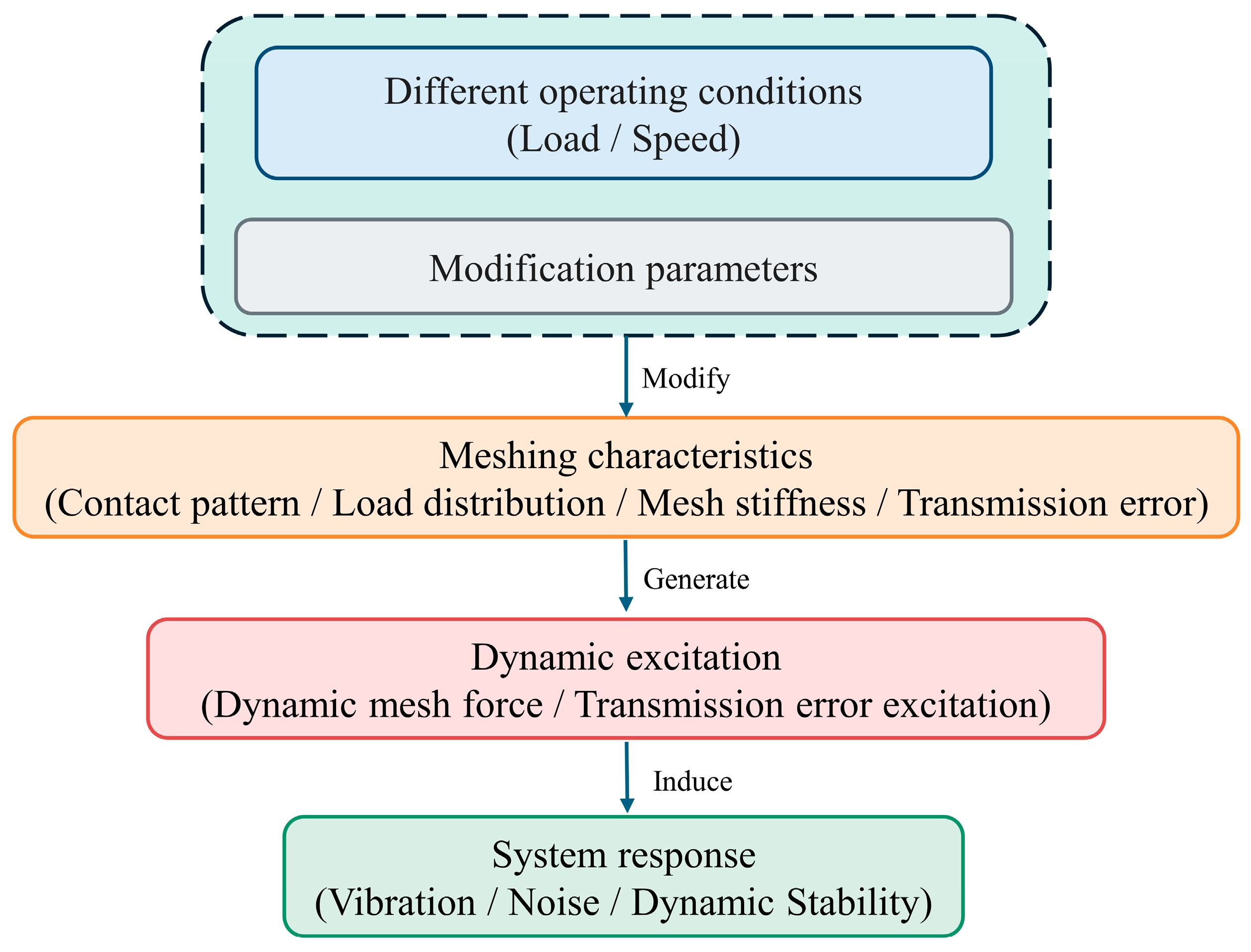
In summary, modification parameters do not directly determine vibration and noise. Instead, they alter contact conditions, mesh stiffness, and transmission error, which subsequently affect dynamic excitation and system response, as illustrated in Figure 7.
However, long-term service analysis must also consider how gear modification regulates wear distribution and how wear-induced tooth-flank changes feed back into meshing characteristics. To address this issue, a limited number of studies have begun to investigate the relationship between gear modification and tooth-flank wear. Huangfu et al. [87] developed a three-dimensional wear prediction model for thin-walled gears that incorporated tooth-flank wear and lead modification. They found that lead modification compensates for load maldistribution caused by the thin-walled structure, reduces local contact stress, and, in their case study, mitigates severe wear near tooth-flank edges. These results indicate that modification not only affects the initial meshing condition but may also alter the location and severity of subsequent wear by improving load distribution.
Sánchez et al. [88] further investigated the time-varying mesh stiffness, load distribution, and transmission error of spur gears under the combined effects of modification and tooth-flank wear. The wear depth generated during each meshing cycle was treated as additional clearance in the subsequent meshing process. The results showed that tooth-flank wear alters the contact interval and load distribution and generally increases transmission error. However, under certain contact ratio and modification conditions, wear may reduce the peak-to-peak transmission error and mean dynamic load. Liu et al. [89] investigated the effects of the profile shift coefficient and tooth-flank wear evolution on the time-varying mesh stiffness of spur gears. Under the operating conditions considered, positive profile shift reduced wear depth, whereas negative profile shift aggravated wear. These studies demonstrate that the effects of modification or profile shift on wear cannot be evaluated independently of the specific geometry and operating conditions.
Overall, gear modification research has established a relatively systematic theoretical framework encompassing mesh stiffness, load distribution, static and dynamic transmission errors, vibration and noise, nonlinear stability, and assembly errors. Appropriate modification can improve the initial contact condition and reduce dynamic loading, but its effectiveness is strongly dependent on load, structure, and operating conditions. Existing studies addressing the combined effects of modification and tooth-flank wear have mainly focused on mesh stiffness, static transmission error, or gears with specific structural configurations. They have not yet adequately described the long-term feedback effects of modification on lubricant-film behavior, the friction coefficient, wear rates, and system dynamic responses. Consequently, a modification design optimized solely for the initial transmission error or dynamic load cannot ensure sustained effectiveness throughout the degradation process. Future assessments should jointly incorporate wear state, lubrication conditions, and assembly deviations when evaluating the applicability of modification parameters.

6. Conclusions and Future Research Directions

This paper reviews progressive tooth-flank wear prediction, gear tribodynamics, the dynamic effects of wear, and gear modifications. The following conclusions can be drawn:
(1)
A fundamental methodology for predicting progressive gear wear has been established based on the Archard model, contact analysis, and tooth-flank geometry updating. Early studies generally adopted dry-contact or quasi-static loading assumptions, facilitating the analysis of tooth-profile evolution and wear distribution. In recent years, mixed EHL, surface roughness, temperature rise, lubricant degradation, and complex assembly conditions have gradually been incorporated into wear models. Existing models can describe the effects of lubricant-film load-carrying capacity and asperity contact on wear, while evolving lubrication states and surface conditions are also relevant to lubrication-related damage such as micropitting. However, wear coefficients are still frequently determined empirically, and dynamic meshing forces, lubrication conditions, and tooth-flank geometry have not yet been updated synchronously.
(2)
Tribodynamic studies demonstrate that friction force, lubricant-film stiffness, frictional power loss and damping, and temperature rise vary with dynamic loading, relative velocity, and lubrication conditions and therefore cannot simply be treated as fixed boundary conditions. By altering the tooth profile, contact interval, load sharing, and backlash, tooth-flank wear further affects time-varying mesh stiffness, transmission error, and dynamic loading. Existing studies have separately revealed the effects of dynamics on wear and those of wear on dynamics. Nevertheless, a unified description of the long-term bidirectional feedback among surface topography evolution, lubrication conditions, frictional behavior, and dynamic meshing forces remains lacking.
(3)
Assembly errors, parameter uncertainties, and gear modification all alter actual contact conditions and system dynamic characteristics. Center-distance deviations, eccentricity, and misalignment may induce load maldistribution and edge contact, while uncertainties in lubrication parameters, modification parameters, and dynamic loads broaden the prediction intervals of transmission error and dynamic response. Appropriate gear modification can improve the initial contact condition and suppress dynamic loading, but its effectiveness varies with operating conditions and wear state. Therefore, life-cycle gear design must consider the coupled relationships among errors, lubrication, wear, and modification.
Based on these findings, future research should focus on the following three directions:
(1)
Closed-loop friction–wear-dynamics modeling for long-term service should be developed. Dynamic meshing forces should drive transient lubrication and friction calculations, while tooth-flank material removal, tooth-profile updating, and the resulting changes in mesh stiffness and transmission error should be fed back into the dynamic equations. The key challenge is not simply to combine multiple submodels but to define the state-updating relationships among dynamic loading, lubricant-film conditions, surface topography, and wear rate. The predictive capability of such models should be validated through long-term experiments.
(2)
Assembly errors and multiple sources of uncertainty should be incorporated into wear evolution analysis. Further studies should determine how center-distance deviations, eccentricity, misalignment, manufacturing errors, lubrication parameters, and load fluctuations jointly alter contact trajectories, local lubricant-film conditions, and accumulated wear distributions. For engineering systems with insufficient statistical information, interval or correlated uncertainty representations may be employed to avoid overly idealized predictions of service life and dynamic response based on single deterministic parameter values.
(3)
Gear modification design should account for in-service degradation. Most existing modification parameters are determined for initial tooth-flank geometry and rated operating conditions and therefore cannot guarantee sustained effectiveness after wear occurs. Future modification design may treat accumulated wear, assembly errors, and lubrication conditions as constraints while jointly optimizing wear distribution, transmission error, dynamic loading, and contact load maldistribution. This approach would enable modification parameters to be selected for different service stages, transforming gear modification from a means of optimizing initial performance into a life-cycle design strategy for maintaining transmission performance.

Author Contributions

W.L.—Writing—original draft and investigation. H.Y.—Conceptualization, writing—review and editing, and funding acquisition. Y.W.—Writing—review and editing and resources. J.L.—Writing—review and editing and supervision. All authors have read and agreed to the published version of the manuscript.

Funding

This work was funded by the National Natural Science Foundation of China (grant No. 52275042), the “Science and Innovation Yongjiang 2035” Key R&D Program of Ningbo City, China (grant No. 2025Z005), and the Zhenhai District Major Special Project Plan for Technological Breakthroughs during the 14th Five-Year Plan Period (grant No. 2024005).

Data Availability Statement

No new data were created or analyzed in this study. Data sharing is not applicable to this article.

Acknowledgments

To ensure readability, this article was polished for grammar using ChatGPT 5.6sol during the writing process.

Conflicts of Interest

Author Y.W. is employed by the company Zhejiang XiaSha Precision Manufacturing Co., Ltd. The remaining authors declare that the research was conducted in the absence of any commercial or financial relationships that could be construed as a potential conflict of interest. The funding sponsors had no role in the design of the study; in the collection, analyses, or interpretation of data; in the writing of the manuscript; or in the decision to publish the results.

References

  1. ISO 6336-1:2019; Calculation of Load Capacity of Spur and Helical Gears—Part 1: Basic Principles, Introduction and General Influence Factors. International Organization for Standardization ISO: Geneva, Switzerland, 2019.
  2. ISO 10825-1:2022; Gears—Wear and Damage to Gear Teeth—Part 1: Nomenclature and Characteristics. International Organization for Standardization ISO: Geneva, Switzerland, 2022.
  3. ANSI/AGMA 1010-F14; Appearance of Gear Teeth—Terminology of Wear and Failure. American Gear Manufacturers Association AGMA: Alexandria, VA, USA, 2014.
  4. Bhushan, B. Introduction to Tribology, 2nd ed.; John Wiley & Sons: Chichester, UK, 2013. [Google Scholar]
  5. Kato, K. Wear in Relation to Friction—A Review. Wear 2000, 241, 151–157. [Google Scholar] [CrossRef] [Scilit]
  6. Sagraloff, N.; Winkler, K.J.; Tobie, T.; Stahl, K.; Folland, C.; Asam, T. Investigations on the Scuffing and Wear Characteristic Performance of an Oil Free Water-Based Lubricant for Gear Applications. Lubricants 2021, 9, 24. [Google Scholar] [CrossRef] [Scilit]
  7. Bergant, Z.; Šturm, R.; Zorko, D.; Černe, B. Fatigue and Wear Performance of Autoclave-Processed and Vacuum-Infused Carbon Fibre Reinforced Polymer Gears. Polymers 2023, 15, 1767. [Google Scholar] [CrossRef] [Scilit] [PubMed]
  8. Sari, M.R.; Haiahem, A.; Flamand, L. Effect of Lubricant Contamination on Gear Wear. Tribol. Lett. 2007, 27, 119–126. [Google Scholar] [CrossRef] [Scilit]
  9. Flodin, A.; Andersson, S. Simulation of Mild Wear in Spur Gears. Wear 1997, 207, 16–23. [Google Scholar] [CrossRef] [Scilit]
  10. Flodin, A.; Andersson, S. Simulation of Mild Wear in Helical Gears. Wear 2000, 241, 123–128. [Google Scholar] [CrossRef] [Scilit]
  11. Bajpai, P.; Kahraman, A.; Anderson, N.E. A Surface Wear Prediction Methodology for Parallel-Axis Gear Pairs. J. Tribol. 2004, 126, 597–605. [Google Scholar] [CrossRef] [Scilit]
  12. Wu, S.; Cheng, H.S. Sliding Wear Calculation in Spur Gears. J. Tribol. 1993, 115, 493–500. [Google Scholar] [CrossRef] [Scilit]
  13. Wang, H.; Zhou, C.; Lei, Y.; Liu, Z. An Adhesive Wear Model for Helical Gears in Line-Contact Mixed Elastohydrodynamic Lubrication. Wear 2019, 426–427, 896–909. [Google Scholar] [CrossRef] [Scilit]
  14. Su, R.; Cao, W.; Jin, Z.; Wang, Y.; Ding, L.; Yan, Y.; Xu, C.; Maqsood, M.; Wang, D.; Khara, N. Prediction of Elastohydrodynamic Lubrication Performance and Corrosion Wear in a Gearbox with Deteriorating Lubricants. Wear 2025, 571, 205801. [Google Scholar] [CrossRef] [Scilit]
  15. Jia, C.; Zhu, C.; Liu, H.; Wei, P.; Zhu, J.; Xu, Y. Comparative Study on Calculation Standards for Scuffing Load Capacity of Cylindrical Involute Gears. J. Mech. Transm. 2022, 46, 86–92. [Google Scholar] [CrossRef]
  16. Morales-Espejel, G.E.; Rycerz, P.; Kadiric, A. Prediction of Micropitting Damage in Gear Teeth Contacts Considering the Concurrent Effects of Surface Fatigue and Mild Wear. Wear 2018, 398–399, 99–115. [Google Scholar] [CrossRef] [Scilit]
  17. Osman, T.; Velex, P. Static and Dynamic Simulations of Mild Abrasive Wear in Wide-Faced Solid Spur and Helical Gears. Mech. Mach. Theory 2010, 45, 911–924. [Google Scholar] [CrossRef] [Scilit]
  18. Park, D.; Kahraman, A. A Surface Wear Model for Hypoid Gear Pairs. Wear 2009, 267, 1595–1604. [Google Scholar] [CrossRef] [Scilit]
  19. Park, D.; Kolivand, M.; Kahraman, A. Prediction of Surface Wear of Hypoid Gears Using a Semi-Analytical Contact Model. Mech. Mach. Theory 2012, 52, 180–194. [Google Scholar] [CrossRef] [Scilit]
  20. Park, D.; Kolivand, M.; Kahraman, A. An Approximate Method to Predict Surface Wear of Hypoid Gears Using Surface Interpolation. Mech. Mach. Theory 2014, 71, 64–78. [Google Scholar] [CrossRef] [Scilit]
  21. Chen, Z.; Ji, P. Study on Wear in Spur Gears Based on an Improved Load Distribution Model Considering the Effects of Corner Contact. Eng. Fail. Anal. 2020, 115, 104605. [Google Scholar] [CrossRef] [Scilit]
  22. Wang, H.; Zhou, C.; Wang, H.; Hu, B.; Liu, Z. A Novel Contact Model for Rough Surfaces Using Piecewise Linear Interpolation and Its Application in Gear Wear. Wear 2021, 476, 203685. [Google Scholar] [CrossRef] [Scilit]
  23. Sun, Y.; Li, Y.; Zhang, Q.; Qin, X.; Chen, K. Wear Analysis and Simulation of Small Module Gear Based on Archard Model. Eng. Fail. Anal. 2023, 144, 106990. [Google Scholar] [CrossRef] [Scilit]
  24. Jangra, D.; Antil, P.; Thakur, P.; Ankur, K. Gear Sliding Wear: The Role of Radial, Axial, and Combined Misalignment. J. Mech. Sci. Technol. 2025, 39, 5375–5383. [Google Scholar] [CrossRef] [Scilit]
  25. He, Z.; Hu, Y.; Zheng, X.; Yu, Y. A Calculation Method for Tooth Wear Depth Based on the Finite Element Method That Considers the Dynamic Mesh Force. Machines 2022, 10, 69. [Google Scholar] [CrossRef] [Scilit]
  26. Zhao, J.; Li, Z.; Zhang, H.; Zhu, R. Study on Sliding Wear Characteristics of Non-Gaussian Rough Surface in Mixed Lubrication. Tribol. Trans. 2022, 65, 621–632. [Google Scholar] [CrossRef] [Scilit]
  27. Janakiraman, V.; Li, S.; Kahraman, A. An Investigation of the Impacts of Contact Parameters on Wear Coefficient. J. Tribol. 2014, 136, 031602. [Google Scholar] [CrossRef] [Scilit]
  28. Masjedi, M.; Khonsari, M.M. On the Prediction of Steady-State Wear Rate in Spur Gears. Wear 2015, 342–343, 234–243. [Google Scholar] [CrossRef] [Scilit]
  29. ISO/TR 15144-2:2014; Calculation of Micropitting Load Capacity of Cylindrical Spur and Helical Gears—Part 2: Calculation of Micropitting Safety Factors. International Organization for Standardization: Geneva, Switzerland, 2014.
  30. Sagraloff, N.; Tobie, T.; Stahl, K. Suitability of the Test Results of Micropitting Tests Acc. to FVA 54/7 for Modern Practical Gear Applications. Forsch. Im Ingenieurwesen 2022, 86, 471–481. [Google Scholar] [CrossRef] [Scilit]
  31. Brummer, M.; Koenig, J.; Tobie, T.; Stahl, K. Investigations on the Influence of Synthetic Lubricants on the Pitting Load Carrying Capacity of Cylindrical Gears. Tribol. Trans. 2025, 68, 156–170. [Google Scholar] [CrossRef] [Scilit]
  32. Wainwright, B.; Kadiric, A. Surface Fatigue in Lubricated Contacts: Mapping the Failure Modes of Micropitting versus Macropitting. Int. J. Fatigue 2025, 197, 108908. [Google Scholar] [CrossRef] [Scilit]
  33. Xiao, Z.; Shi, X.; Wang, X.; Ma, X.; Han, Y. Lubrication Analysis and Wear Mechanism of Heavily Loaded Herringbone Gears with Profile Modifications in Full Film and Mixed Lubrication Point Contacts. Wear 2021, 477, 203790. [Google Scholar] [CrossRef] [Scilit]
  34. Zhao, J.; Sheng, W.; Li, Z.; Zhang, H.; Zhu, R. Effect of Lubricant Selection on the Wear Characteristics of Spur Gear under Oil-Air Mixed Lubrication. Tribol. Int. 2022, 167, 107382. [Google Scholar] [CrossRef] [Scilit]
  35. Liu, H.; Liu, H.; Zhu, C.; Zhou, Y. A Review on Micropitting Studies of Steel Gears. Coatings 2019, 9, 42. [Google Scholar] [CrossRef] [Scilit]
  36. Yin, Z.; Wang, H.; Fu, X.; Fan, Z.; Ma, Q. Study on the Influence of Tooth Surface Wear on the Lubrication Performance of Double Involute Gear Transmission. Sci. Rep. 2025, 15, 7612. [Google Scholar] [CrossRef] [Scilit] [PubMed]
  37. Dong, N.; Tong, R.; Zhang, C.; Li, S.; Li, Y.; Wan, S. An Improved Model of Dynamic Wear Prediction for Solid-Lubricated Planetary Gear Sets Considering Thermal Effects. Wear 2026, 584–585, 206415. [Google Scholar] [CrossRef] [Scilit]
  38. Li, S.; Kahraman, A. A Tribo-Dynamic Model of a Spur Gear Pair. J. Sound Vib. 2013, 332, 4963–4978. [Google Scholar] [CrossRef] [Scilit]
  39. Li, S. A Thermal Tribo-Dynamic Mechanical Power Loss Model for Spur Gear Pairs. Tribol. Int. 2015, 88, 170–178. [Google Scholar] [CrossRef] [Scilit]
  40. Ouyang, T.; Huang, H.; Zhou, X.; Pan, M.; Chen, N.; Lv, D. A Finite Line Contact Tribo-Dynamic Model of a Spur Gear Pair. Tribol. Int. 2018, 119, 753–765. [Google Scholar] [CrossRef] [Scilit]
  41. Michaelis, K.; Höhn, B.; Hinterstoißer, M. Influence Factors on Gearbox Power Loss. Ind. Lubr. Tribol. 2011, 63, 46–55. [Google Scholar] [CrossRef] [Scilit]
  42. Li, Z.; Zhu, C.; Liu, H.; Gu, Z. Mesh Stiffness and Nonlinear Dynamic Response of a Spur Gear Pair Considering Tribo-Dynamic Effect. Mech. Mach. Theory 2020, 153, 103989. [Google Scholar] [CrossRef] [Scilit]
  43. Hu, B.; Zhou, C.; Wang, H.; Chen, S. Nonlinear Tribo-Dynamic Model and Experimental Verification of a Spur Gear Drive under Loss-of-Lubrication Condition. Mech. Syst. Signal Process. 2021, 153, 107509. [Google Scholar] [CrossRef] [Scilit]
  44. Wang, Z.; Shi, Z.; Yang, J.; Huang, X.; Zhou, Q.; Pu, W. Unified Gear Tribo-Dynamic of Transient Mixed Lubrication and Nonlinear Dynamics and Its Experimental Validation. Mech. Syst. Signal Process. 2025, 223, 111860. [Google Scholar] [CrossRef] [Scilit]
  45. Wu, H.; Li, H.; Huang, K.; Zhang, X. Analysis of friction dynamic characteristics of high-speed and heavy-load helical gear transmission. Chin. J. Constr. Mach. 2025, 23, 140–145. [Google Scholar] [CrossRef]
  46. Ding, H.; Kahraman, A. Interactions between Nonlinear Spur Gear Dynamics and Surface Wear. J. Sound Vib. 2007, 307, 662–679. [Google Scholar] [CrossRef] [Scilit]
  47. Liu, X.; Yang, Y.; Zhang, J. Investigation on Coupling Effects between Surface Wear and Dynamics in a Spur Gear System. Tribol. Int. 2016, 101, 383–394. [Google Scholar] [CrossRef] [Scilit]
  48. Shen, Z.; Qiao, B.; Yang, L.; Luo, W.; Chen, X. Evaluating the Influence of Tooth Surface Wear on TVMS of Planetary Gear Set. Mech. Mach. Theory 2019, 136, 206–223. [Google Scholar] [CrossRef] [Scilit]
  49. Ma, H.; Zeng, J.; Feng, R.; Pang, X.; Wen, B. An Improved Analytical Method for Mesh Stiffness Calculation of Spur Gears with Tip Relief. Mech. Mach. Theory 2016, 98, 64–80. [Google Scholar] [CrossRef] [Scilit]
  50. Pleguezuelos, M.; Sánchez, M.B.; Pedrero, J.I. Analytical Model for Meshing Stiffness, Load Sharing, and Transmission Error for Spur Gears with Profile Modification under Non-Nominal Load Conditions. Appl. Math. Model. 2021, 97, 344–365. [Google Scholar] [CrossRef] [Scilit]
  51. Pedrero, J.I.; Pleguezuelos, M.; Sánchez, M.B. Analytical Model for Meshing Stiffness, Load Sharing, and Transmission Error for Helical Gears with Profile Modification. Mech. Mach. Theory 2023, 185, 105340. [Google Scholar] [CrossRef] [Scilit]
  52. Shen, Z.; Qiao, B.; Yang, L.; Luo, W.; Yang, Z.; Chen, X. Fault Mechanism and Dynamic Modeling of Planetary Gear with Gear Wear. Mech. Mach. Theory 2021, 155, 104098. [Google Scholar] [CrossRef] [Scilit]
  53. Shen, Z.; Yang, L.; Qiao, B.; Luo, W.; Chen, X.; Yan, R. Mesh Relationship Modeling and Dynamic Characteristic Analysis of External Spur Gears with Gear Wear. Front. Mech. Eng. 2022, 17, 9. [Google Scholar] [CrossRef] [Scilit]
  54. Geng, Z.; Xiao, K.; Li, J.; Wang, J. Bifurcation and Chaos of a Spur Gear Transmission System With Non-Uniform Wear. J. Vib. Acoust. 2021, 143, 031004. [Google Scholar] [CrossRef] [Scilit]
  55. Zhang, X.; Zhong, J.; Li, W.; Bocian, M. Nonlinear Dynamic Analysis of High-Speed Gear Pair with Wear Fault and Tooth Contact Temperature for a Wind Turbine Gearbox. Mech. Mach. Theory 2022, 173, 104840. [Google Scholar] [CrossRef] [Scilit]
  56. Cao, P.; Li, Q.; Feng, K.; Qin, Y. Dynamic Modeling of Spur Gear Transmission System with Evolutive Coupling Fault of Fatigue Crack and Wear. Eng. Fail. Anal. 2024, 156, 107820. [Google Scholar] [CrossRef] [Scilit]
  57. Liu, N.; Ma, H.; Zhao, Z.; Wang, P.; Zhao, X. Dynamic Characteristics of Gear-Rotor System with Gear Eccentricity and Wear Fault. Nonlinear Dyn. 2024, 112, 16003–16035. [Google Scholar] [CrossRef] [Scilit]
  58. Zhao, J.; Yu, X.; Sheng, W.; Li, Z.; Zhang, H.; Zhu, R. Effect of Machined Tooth Surface Mixed Lubrication Sliding Wear on Gear Dynamic Characteristics. Machines 2022, 11, 25. [Google Scholar] [CrossRef] [Scilit]
  59. Li, Z.; Xiao, H.; Tang, Y.; Liang, G.; Wang, L.; Yang, J. A Deterministic Model of Surface Profile Degradation for Evaluating Time-Varying Mesh Stiffness and Dynamic Responses of Spur Gear Considering Tooth Surface Wear Evolution. Mech. Syst. Signal Process. 2025, 225, 112313. [Google Scholar] [CrossRef] [Scilit]
  60. Feng, K.; Xiao, H.; Zhang, J.; Ni, Q. A Digital Twin Methodology for Vibration-Based Monitoring and Prediction of Gear Wear. Wear 2025, 571, 205806. [Google Scholar] [CrossRef] [Scilit]
  61. Xiong, Q.; Liu, X.; Liu, Y.; Wang, J.; Zhang, J. Interaction between Gear Wear and Dynamic Behavior Considering Interface Characteristics. Tribol. Int. 2025, 212, 111013. [Google Scholar] [CrossRef] [Scilit]
  62. Hu, Y.-H.; Du, Q.-G.; Xie, S.-H. Nonlinear Dynamic Modeling and Analysis of Spur Gears Considering Uncertain Interval Shaft Misalignment with Multiple Degrees of Freedom. Mech. Syst. Signal Process. 2023, 193, 110261. [Google Scholar] [CrossRef] [Scilit]
  63. Luo, Y.; Baddour, N.; Liang, M. Effects of Gear Center Distance Variation on Time Varying Mesh Stiffness of a Spur Gear Pair. Eng. Fail. Anal. 2017, 75, 37–53. [Google Scholar] [CrossRef] [Scilit]
  64. Cao, Z.; Shao, Y.; Rao, M.; Yu, W. Effects of the Gear Eccentricities on the Dynamic Performance of a Planetary Gear Set. Nonlinear Dyn. 2018, 91, 1–15. [Google Scholar] [CrossRef] [Scilit]
  65. Xu, Z.; Yu, W.; Shao, Y.; Yang, X.; Nie, C.; Peng, D. Dynamic Modeling of the Planetary Gear Set Considering the Effects of Positioning Errors on the Mesh Position and the Corner Contact. Nonlinear Dyn. 2022, 109, 1551–1569. [Google Scholar] [CrossRef] [Scilit]
  66. Wei, S.; Zhao, J.; Han, Q.; Chu, F. Dynamic Response Analysis on Torsional Vibrations of Wind Turbine Geared Transmission System with Uncertainty. Renew. Energy 2015, 78, 60–67. [Google Scholar] [CrossRef] [Scilit]
  67. Wei, S.; Chu, F.-L.; Ding, H.; Chen, L.-Q. Dynamic Analysis of Uncertain Spur Gear Systems. Mech. Syst. Signal Process. 2021, 150, 107280. [Google Scholar] [CrossRef] [Scilit]
  68. Chen, Z.; Jiang, Y.; Li, S.; Tong, Z.; Tong, S.; Tang, N. Effect of Lubricant Viscosity on Dynamics of High-Precision Gear Considering Lubricant-Induced Backlash Reduction. Tribol. Int. 2022, 168, 107447. [Google Scholar] [CrossRef] [Scilit]
  69. Jiang, Y.; Chen, Z.; Tong, S.; Li, S.; Tong, Z. Gear Tribodynamic Modeling and Analysis Considering Tooth Profile Modification. Tribol. Int. 2023, 178, 108023. [Google Scholar] [CrossRef] [Scilit]
  70. Chen, Z.; Jiang, Y.; Li, S.; Tong, Z.; Tong, S.; Tang, N. Uncertainty Propagation of Correlated Lubricant Properties in Gear Tribodynamic System. Tribol. Int. 2023, 179, 107812. [Google Scholar] [CrossRef] [Scilit]
  71. Chen, Z.; Sha, H.; Li, S.; Tong, Z.; Tong, S. Stochastic Uncertain Lubrication in Gear Transmission Subjected to Tribodynamic Loading. Friction 2024, 12, 1741–1756. [Google Scholar] [CrossRef] [Scilit]
  72. Jiang, Y.; Tong, S.; Tong, Z.; Li, S.; Cheng, W. Tribodynamic Analysis of Spur Gear Drives with Uncertain Time-Variant Loads: An Interval Process Approach. Mech. Mach. Theory 2024, 191, 105511. [Google Scholar] [CrossRef] [Scilit]
  73. Lee, C.; Lin, H.H.; Oswald, F.B.; Townsend, D.P. Influence of Linear Profile Modification and Loading Conditions on The Dynamic Tooth Load and Stress of High-Contact-Ratio Spur Gears. J. Mech. Des. 1991, 113, 473–480. [Google Scholar] [CrossRef] [Scilit]
  74. Hsi Lin, H.; Oswald, F.B.; Townsend, D.P. Dynamic Loading of Spur Gears with Linear or Parabolic Tooth Profile Modifications. Mech. Mach. Theory 1994, 29, 1115–1129. [Google Scholar] [CrossRef] [Scilit]
  75. Kahraman, A.; Blankenship, G.W. Effect of Involute Tip Relief on Dynamic Response of Spur Gear Pairs. J. Mech. Des. 1999, 121, 313–315. [Google Scholar] [CrossRef] [Scilit]
  76. Velex, P.; Bruyère, J.; Houser, D.R. Some Analytical Results on Transmission Errors in Narrow-Faced Spur and Helical Gears: Influence of Profile Modifications. J. Mech. Des. 2011, 133, 031010. [Google Scholar] [CrossRef] [Scilit]
  77. Ghosh, S.S.; Chakraborty, G. On Optimal Tooth Profile Modification for Reduction of Vibration and Noise in Spur Gear Pairs. Mech. Mach. Theory 2016, 105, 145–163. [Google Scholar] [CrossRef] [Scilit]
  78. Pleguezuelos, M.; Sánchez, M.B.; Pedrero, J.I. Control of Transmission Error of High Contact Ratio Spur Gears with Symmetric Profile Modifications. Mech. Mach. Theory 2020, 149, 103839. [Google Scholar] [CrossRef] [Scilit]
  79. Bruyère, J.; Velex, P. Towards General Performance Diagrams to Define Optimum Profile and Lead Modifications with Regard to Transmission Error in Spur and Helical Gears. Mech. Mach. Theory 2022, 176, 105021. [Google Scholar] [CrossRef] [Scilit]
  80. Li, S. Effects of Misalignment Error, Tooth Modifications and Transmitted Torque on Tooth Engagements of a Pair of Spur Gears. Mech. Mach. Theory 2015, 83, 125–136. [Google Scholar] [CrossRef] [Scilit]
  81. Zou, D.; Wang, L.; Yang, L.; Yu, W.; Xie, L. Dynamic Characteristics of a Spur Gear Pair under the Coupled Effects of Angular Misalignment Fault and Tooth Modification. Int. J. Non-Linear Mech. 2023, 155, 104453. [Google Scholar] [CrossRef] [Scilit]
  82. Ma, H.; Pang, X.; Feng, R.; Wen, B. Evaluation of Optimum Profile Modification Curves of Profile Shifted Spur Gears Based on Vibration Responses. Mech. Syst. Signal Process. 2016, 70–71, 1131–1149. [Google Scholar] [CrossRef] [Scilit]
  83. Cirelli, M.; Giannini, O.; Valentini, P.P.; Pennestrì, E. Influence of Tip Relief in Spur Gears Dynamic Using Multibody Models with Movable Teeth. Mech. Mach. Theory 2020, 152, 103948. [Google Scholar] [CrossRef] [Scilit]
  84. Hajjaj, A.Z.; Corrigan, K.; Mohammadpour, M.; Theodossiades, S. On the Stability Analysis of Gear Pairs with Tooth Profile Modification. Mech. Mach. Theory 2022, 174, 104888. [Google Scholar] [CrossRef] [Scilit]
  85. Autiero, M.; Paoli, G.; Cirelli, M.; Valentini, P.P. The Effect of Different Profile Modifications on the Static and Dynamic Transmission Error of Spur Gears. Mech. Mach. Theory 2024, 201, 105752. [Google Scholar] [CrossRef] [Scilit]
  86. Zhou, D.; Guo, Y.; Yang, J.; Zhang, Y. Study on the Parameter Influences of Gear Tooth Profile Modification and Transmission Error Analysis. Machines 2024, 12, 316. [Google Scholar] [CrossRef] [Scilit]
  87. Huangfu, Y.; Zhao, Z.; Ma, H.; Han, H.; Chen, K. Effects of Tooth Modifications on the Dynamic Characteristics of Thin-Rimmed Gears under Surface Wear. Mech. Mach. Theory 2020, 150, 103870. [Google Scholar] [CrossRef] [Scilit]
  88. Sánchez, M.B.; Pleguezuelos, M.; Pedrero, J.I. Influence of Profile Modification on the Transmission Error of Spur Gears under Surface Wear. Mech. Mach. Theory 2024, 191, 105473. [Google Scholar] [CrossRef] [Scilit]
  89. Liu, W.; Zhu, R.; Zhou, W.; Wang, J. Calculation and Analysis of TVMS Considering Profile Shifts and Surface Wear Evolution Process of Spur Gear. Chin. J. Mech. Eng. 2024, 37, 73. [Google Scholar] [CrossRef] [Scilit]
Figure 1. Schematic illustrations of different gear damage modes: (a) Abrasive wear. (b) Adhesive wear. (c) Gear fatigue pitting. (d) Gear scuffing [6,7].
Lubricants 14 00334 g001
Figure 2. Iterative framework for gear wear prediction without lubrication modeling.
Lubricants 14 00334 g002
Figure 3. Coupled lubrication wear prediction framework for gear contacts.
Lubricants 14 00334 g003
Figure 4. Bidirectional coupling between gear system dynamics and tribological interface behavior.
Lubricants 14 00334 g004
Figure 6. Typical gear assembly errors: (a) staggered angle misalignment, (b) intersection angle misalignment, (c) center-distance misalignment, and (d) vertical distance misalignment. Adapted from Ref. [62].
Lubricants 14 00334 g006
Figure 7. Conceptual pathway by which tooth modification affects gear dynamic response.
Lubricants 14 00334 g007
Table 1. Formation mechanisms of typical gear tooth-surface damage, representative modeling approaches, and their correlation with progressive wear.
Damage ModeRepresentative Modeling RouteGoverning MechanismCommon CausesTypical Surface CharacteristicsRelationship to the Scope of This Review
Abrasive wearArchard-type local material removal model coupled with contact pressure, sliding distance, and tooth-flank updatingCutting and ploughing by hard particles or surface asperitiesLubricant contamination, foreign particles, increased surface roughnessGrooves, scratches, and gradual material loss from the tooth profileAn important form of progressive wear
Adhesive wearModified Archard-type or mixed-lubrication wear model considering direct asperity contact, friction, and lubricant-film conditionAsperity adhesion, shearing, and material transferInsufficient lubricant film, local film breakdown, high loadLocal material transfer, spalling, or scoringAn important form of progressive wear
Corrosive wearMechanical–chemical coupled model considering lubricant degradation, corrosive medium, and reaction product removalRemoval of chemically generated reaction products during frictionMoisture, oxidation, lubricant degradationRusting, dark spots, pitting, and localized rougheningMay be coupled with mechanical wear
Pitting/micropittingContact-fatigue or micropitting risk model considering cyclic contact stress, roughness, and lubrication conditionInitiation, propagation, and spalling of contact-fatigue cracksCyclic contact stress, low specific film thickness, asperity contactSpalling pits, grey or dull surfaces, and microscopic pitsMay be coupled with wear, but is fundamentally a fatigue damage mode
ScuffingFlash temperature, frictional energy, or lubrication failure criterionSevere adhesion and material tearing at elevated temperaturesHigh speed and heavy load, insufficient lubrication, excessive local temperature riseScuff marks and tearing bands along the sliding directionA sudden and severe surface failure mode
Table 2. Modeling characteristics and applicability of different gear wear prediction methods.
Model CategoryRepresentative Quantitative FormulationMain State VariablesWear-Driving QuantityEngineering ApplicabilityMain Limitation
Quasi-static Archard contact model Δ h i = K / H σ H , i Δ s i Contact stress, sliding distance, hardness, wear coefficientLocal contact stress and sliding distanceBasic wear distribution analysis; low-to-medium-speed operationLubrication and dynamic loading neglected
FEM/semi-analytical contact-wear model Δ h i = K / H p i Δ s i
p i = C g , F N , Ω c
Geometry, curvature, contact area, edge contact, local pressureLocal contact pressure and sliding distanceComplex tooth surfaces, hypoid gears, local and non-uniform wearComputationally demanding for long-term simulation
Dynamic mesh-force wear model F m t = k m t δ t + c m δ ˙ t
Δ h i = K / H σ H , i t Δ s i t
Speed, torque, mesh stiffness, damping, dynamic transmission errorTime-varying contact stress and sliding velocityHigh-speed, heavy-load, time-varying, and near-resonance conditionsLubrication effects often simplified
Mixed-lubrication wear model λ = h m i n R q 1 2 + R q 2 2
W = W f + W a
Δ h i ∝ p a , i Δ s i
Film thickness, roughness, viscosity, load-sharing ratio, frictionAsperity-supported load or equivalent direct-contact pressureLubrication-sensitive and high-power-density gear systemsRequires detailed lubricant and surface parameters
Thermal EHL/friction-wear model q ″ = μ p i v s
η = η ( p i , T )
Δ h i = K T , λ H p a , i Δ s i
Flash temperature, friction coefficient, viscosity, supply condition, speed and loadDirect-contact, frictional heat, and temperature-dependent wear coefficientHigh-speed, heavy-load, thermal-sensitive, and transient operationHigh computational and experimental calibration requirements
Notes: g is the local tooth-flank geometric state; Ω c  is the contact region; F m t  is the time-varying dynamic mesh force; k m t  and c m are the time-varying mesh stiffness and mesh damping, respectively; δ t  is the dynamic transmission displacement along the line of action; p a , i  is the local asperity contact pressure; q ″  is the frictional heat flux; μ  is the friction coefficient; v s is the sliding velocity; η  is the lubricant viscosity dependent on pressure and temperature; and T is the interfacial temperature.
Table 3. Comparative effects of gear modification strategies on mesh stiffness, load distribution, and transmission error.
Modification StrategyMain Geometric EffectEffect on Mesh StiffnessEffect on Load DistributionEffect on Transmission Error
Tip reliefRelieves tooth entry and exit interferenceReduces stiffness in the relieved region; excessive relief may reduce effective mesh stiffnessReduces impact-related local load when properly matchedCan reduce peak-to-peak transmission error
Linear profile modificationIntroduces a linear profile deviationChanges stiffness transition between single- and double-pair contactEffect depends on load and contact ratioAlters dynamic tooth load and transmission error
Parabolic profile modificationProvides a smoother profile transitionCan reduce abrupt stiffness variationPromotes smoother load transfer relative to unsuitable linear formsCan improve dynamic performance
Lead crowning/lead modificationModifies contact along the face widthReduces effective face-width stiffnessMitigates edge loading caused by misalignmentIndirectly affects transmission error through load redistribution
Combined profile and lead modificationSimultaneously regulates line-of-action and face-width contactRequires joint evaluation of stiffness distributionCan balance impact reduction and edge-load controlCan jointly improve static and dynamic transmission error
Modification under evolving wearTreats worn geometry as a changing conditionStiffness changes with wear stateContact region and load sharing evolve during serviceInitial optimum may not remain optimal
Disclaimer/Publisher’s Note: The statements, opinions and data contained in all publications are solely those of the individual author(s) and contributor(s) and not of MDPI and/or the editor(s). MDPI and/or the editor(s) disclaim responsibility for any injury to people or property resulting from any ideas, methods, instructions or products referred to in the content.