Article

Influence of WC Particle Morphology on the Microstructure and Performance of Laser-Cladded Ni-Based WC Composite Coatings on 0Cr13Ni5Mo Steel

1
State Key Laboratory of Cemented Carbide, College of Materials Science and Engineering, Hunan University, Changsha 410000, China
2
State Key Laboratory of Cemented Carbide, Zhuzhou Cemented Carbide Group Co., Ltd., Zhuzhou 412000, China
3
Department of Materials Science and Engineering, State University of New York at Stony Brook, New York, NY 11794, USA
*
Author to whom correspondence should be addressed.
Lubricants 2026, 14(6), 215; https://doi.org/10.3390/lubricants14060215
Submission received: 15 April 2026 / Revised: 8 May 2026 / Accepted: 17 May 2026 / Published: 25 May 2026

Abstract

Ni-based WC composite coatings are widely used to protect hydraulic components, yet the role of WC particle morphology in binder-phase strengthening remains unclear. In this study, two Ni40-based coatings containing 55 wt.% WC were laser-cladded on 0Cr13Ni5Mo steel under identical conditions using either rough spherical WC coating (RWC) or smooth spherical WC coating (SWC). Both coatings were mainly composed of γ-Ni, residual WC, W2C, carbides, and borides. Although the rough WC particles showed about 38% lower intrinsic hardness than the smooth WC particles, the RWC exhibited a 25% higher binder-phase hardness and a 47% higher overall coating hardness. Accordingly, compared with the SWC, the RWC reduced the specific wear rate by about 33% under water-lubricated sliding. In slurry erosion, the RWC consistently showed lower erosion rates and less severe surface damage. The improved performance is attributed to the greater dissolution of rough WC during laser cladding, which strengthened the Ni-based binder and provided more stable support for the hard phases. These results demonstrate that tailoring WC particle morphology is an effective strategy for designing wear- and slurry erosion-resistant Ni-based laser-cladded coatings.

1. Introduction

0Cr13Ni5Mo martensitic stainless steel is widely used in hydraulic machinery because of its good combination of strength, toughness, and corrosion resistance. In practical service, however, components made of this steel are still vulnerable to severe surface damage. For example, Pelton turbine buckets and other flow-exposed parts are subjected to long-term slurry erosion caused by high-speed sand-laden water [1]. These surface damage processes significantly shorten service life and reduce operational reliability. Therefore, surface modification technologies capable of simultaneously improving erosion and wear resistance are of great importance for hydraulic components.
Laser cladding is an effective surface engineering method for producing dense coatings with low dilution and metallurgical bonding to the substrate [2,3]. Among different laser-cladded systems, Ni-based coatings reinforced with WC particles have attracted considerable attention because they combine the toughness and corrosion resistance of the Ni alloy matrix with the high hardness of ceramic carbides [4,5,6,7]. Previous studies have mainly focused on the effects of WC content [8,9,10], particle size [11], alloying additions [12], and processing parameters [13,14] on the microstructure and properties of laser-cladded Ni-based WC coatings. These studies have demonstrated that the final performance of the coating depends not only on the amount of retained WC, but also on the dissolution behavior of WC in the molten pool and the resulting evolution of the binder phase.
Compared with composition and process parameters, the influence of WC particle morphology has been less systematically investigated [15]. In particular, there is still insufficient understanding of how different types of spherical WC particles affect the microstructure and performance of laser-cladded Ni-based coatings under identical powder fraction and cladding conditions. This issue is important because different WC particles may exhibit very different thermal responses during cladding. Rough spherical WC particles prepared by spray granulation and sintering are agglomerated structures formed from fine WC grains. Their intrinsic hardness and strength are generally lower than those of smooth spherical WC particles produced by fusion crushing and plasma spheroidization. From the viewpoint of individual particle properties alone, rough WC would not be expected to provide better erosion or wear resistance. However, during laser cladding, rough WC particles may dissolve more readily into the surrounding binder phase, which can increase matrix hardness and change the load-bearing and damage evolution behavior of the entire coating [16]. Therefore, the coating performance cannot be judged simply by the hardness of the WC particles themselves.
This contradiction highlights the need for a systematic comparison between coatings reinforced by rough and smooth spherical WC particles. In the present study, Ni-based WC composite coatings were fabricated on 0Cr13Ni5Mo steel by laser cladding using 55 wt.% WC and 45 wt.% Ni40. The WC fraction of 55 wt.% was selected because it was the highest addition level that could be achieved without coating cracking under the optimized cladding conditions used in this work. Two kinds of WC particles were employed: rough spherical WC prepared by spray granulation and sintering, and smooth spherical WC prepared by conventional plasma spheroidization. The phase constitution, microstructure, hardness, water-lubricated sliding wear behavior, and slurry erosion resistance of the two coatings were comparatively studied. Special attention was paid to clarifying how WC particle morphology influences WC dissolution during laser cladding, the strengthening of the Ni-based binder phase, and the resulting resistance to Al2O3-induced water-lubricated sliding wear and SiO2-sand-induced erosion. The results are expected to provide guidance for the design of protective coatings for the anti-slurry erosion of Pelton turbine buckets.

2. Materials and Methods

2.1. Substrate and Feedstock Powders

The substrate material was 0Cr13Ni5Mo martensitic stainless steel in the quenched and tempered condition (1080 °C quenching + 600 °C tempering). Before laser cladding, the steel was machined into block specimens, and the surface was ground with abrasive papers, cleaned with acetone, and dried. The nominal chemical composition of the substrate is listed in Table 1.
Ni40 powder was selected because its moderate hardness and good toughness help to avoid cracking while providing sufficient binder strength, and WC powder was used as the reinforcing phase. The nominal chemical composition of the Ni40 powder is given in Table 2.
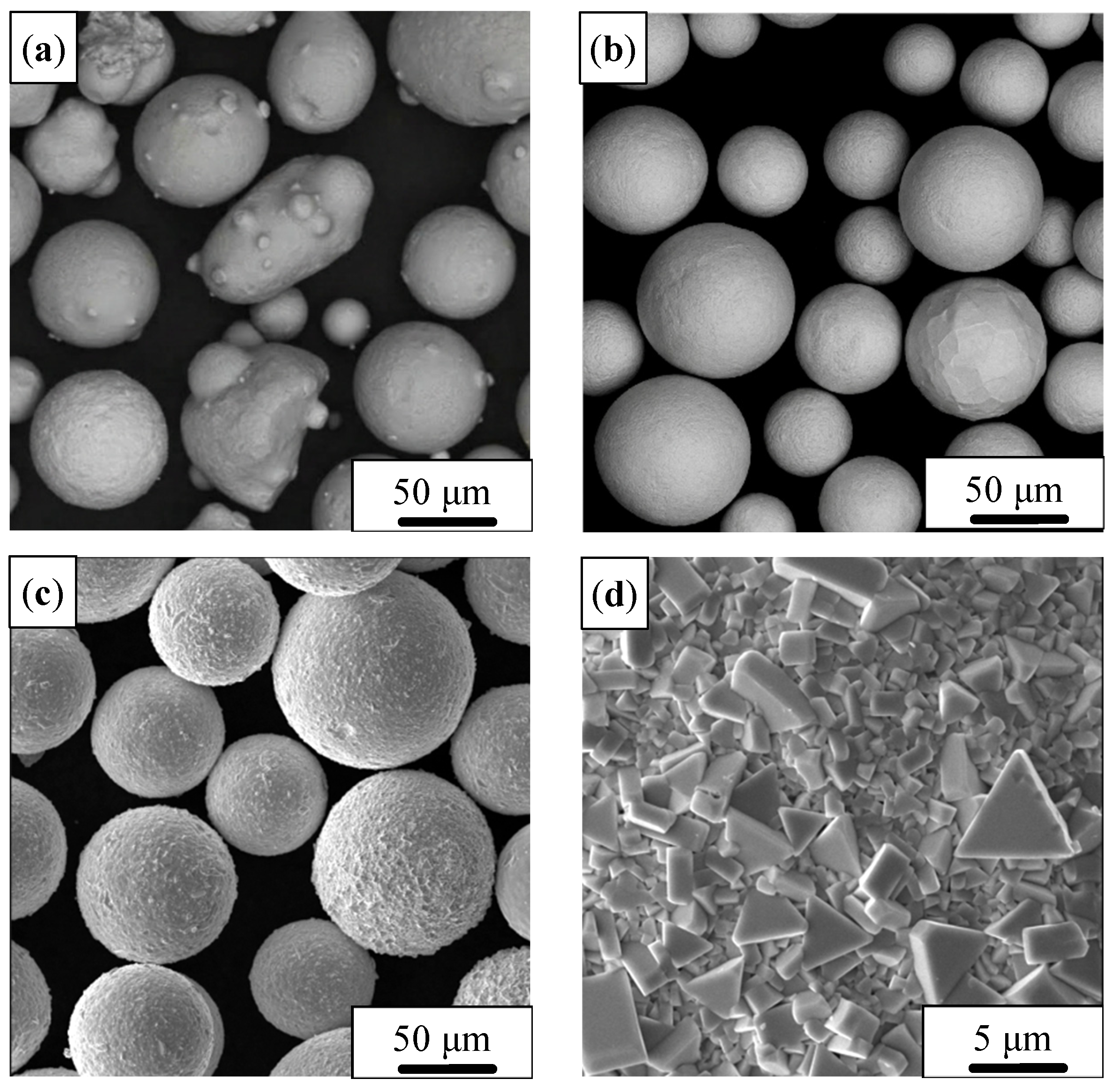
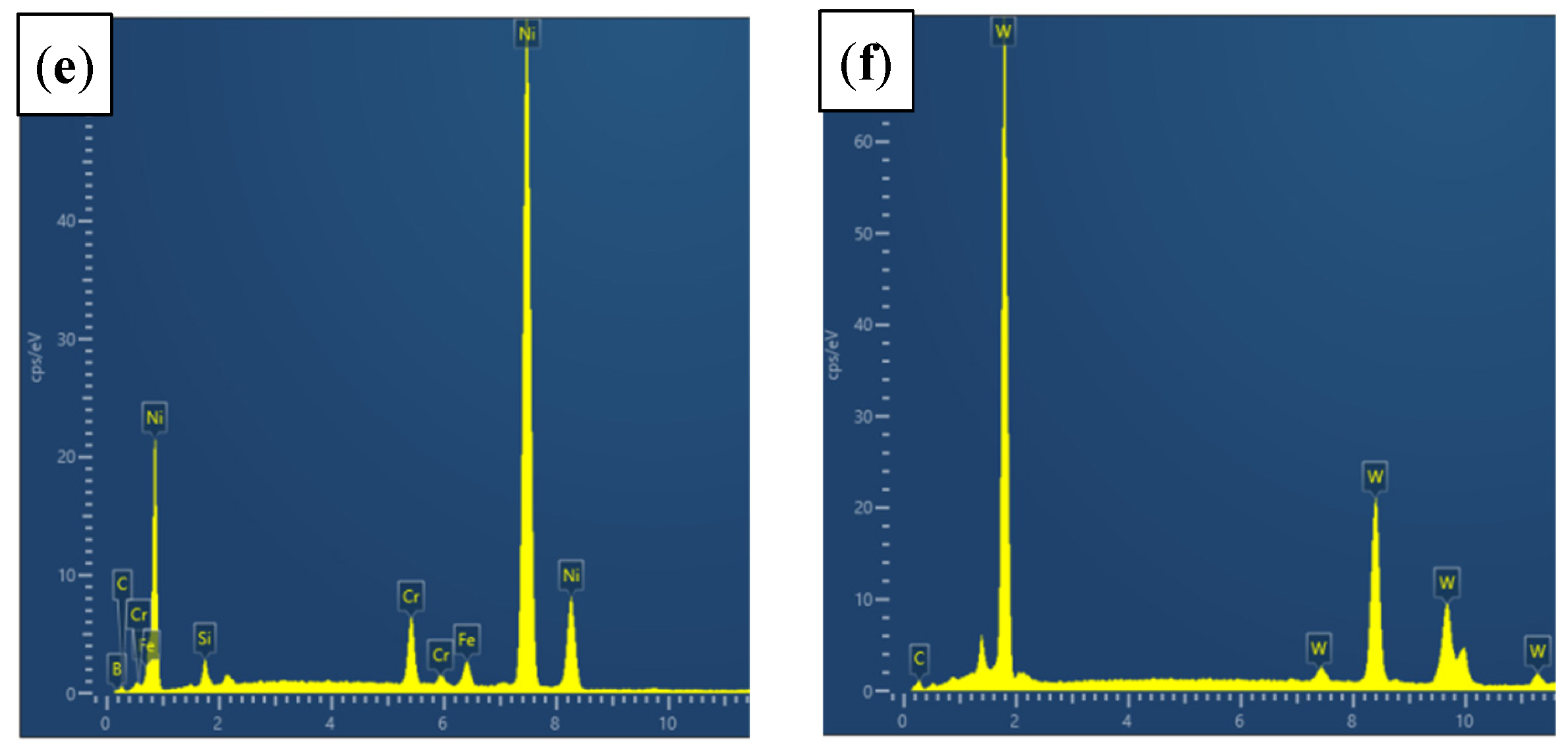
Two types of spherical WC powders were used in this work: rough spherical WC prepared by spray granulation and sintering with a particle size of −100+180 mesh, and smooth spherical WC produced by conventional plasma spheroidization with a particle size of −325+150 mesh. Representative morphologies of the Ni-basd alloy and two WC powders are shown in Figure 1.
For coating preparation, each WC powder was separately blended with Ni40 powder at a fixed proportion of 55 wt.% WC and 45 wt.% Ni40 using a zero-gravity double-shaft paddle mixer, which ensures uniform distribution despite the large density difference. The WC content was set to 55 wt.% because this was the highest addition level that could be achieved without coating cracking under the optimized laser cladding conditions used in this study. Unless otherwise specified, the coating reinforced with rough spherical WC is referred to as the rough-WC coating (RWC), and the coating reinforced with smooth spherical WC is referred to as the smooth-WC coating (SWC).

2.2. Laser Cladding Procedure

Laser cladding was carried out using a JPT-4000 laser cladding system (JPT Opto-Electronics Co., Ltd., Shenzhen, China). Prior to cladding, the substrate surface was prepared as described in Section 2.1. The mixed Ni40/WC powders were then used as the feedstock for coating deposition.
Based on preliminary process optimization, the laser power, spot diameter, scanning speed, and overlap ratio were fixed to produce dense and crack-free coatings. The optimized laser cladding parameters are summarized in Table 3.
Using the same optimized parameters, two types of composite coatings were deposited on 0Cr13Ni5Mo steel: one reinforced with rough spherical WC and the other reinforced with smooth spherical WC. All subsequent phase analysis, microstructural characterization, hardness testing and sliding wear testing were performed on the two coatings and the substrate for comparison, whereas slurry erosion testing was conducted on the two coatings.

2.3. Phase and Microstructural Characterization

The phase constitution of the powders and coatings was analyzed by X-ray diffraction (XRD) using a MiniFlex 600 diffractometer (Rigaku Corporation, Tokyo, Japan) with Cu Kα radiation (λ = 1.5406 Å). The operating voltage and current were 40 kV and 15 mA, respectively. Data were collected in continuous scanning mode over the selected 2θ range at a scanning rate of 10° min−1 with a step size of 0.02°. Phase identification was performed by matching the obtained diffraction peaks to the ICDD PDF-2 database (Release 2024) using MDI Jade 6.5 software, with a tolerance of ±0.1° in 2θ.
For microstructural characterization, the coated samples were sectioned perpendicular to the cladding direction, mounted, ground, and polished. The cross-sectional microstructures, worn surfaces, and eroded surfaces were examined by scanning electron microscopy (SEM). The local chemical compositions of selected regions were analyzed by energy-dispersive X-ray spectroscopy (EDS).

2.4. Hardness Measurements

The hardness of the coatings was characterized at different scales. The cross-sectional hardness distribution of the coatings was measured from the coating surface toward the substrate using a load of 5000 g with the dwell time of 15 s. The average hardness values reported for the coatings were obtained from ten test points along the cross section.

2.5. Sliding Wear Tests

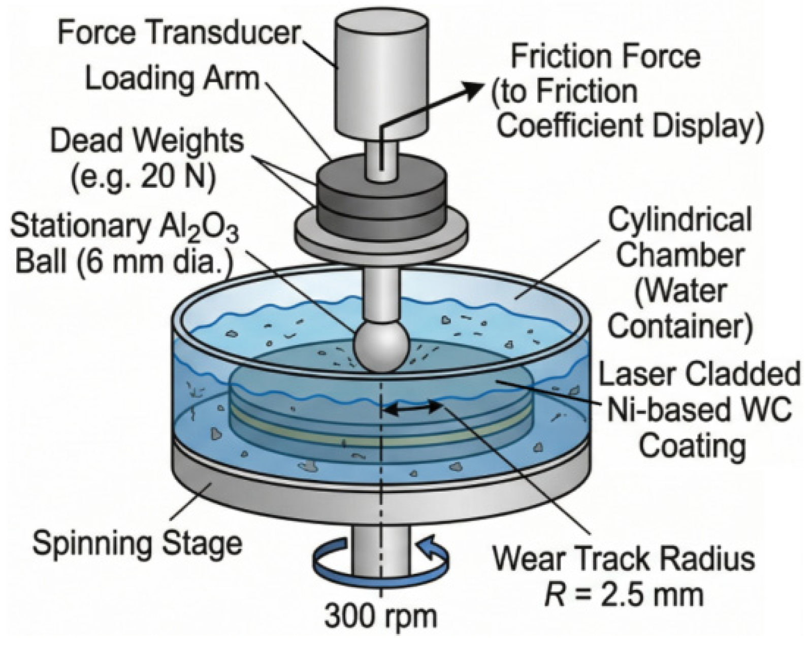
To better simulate the service condition of hydraulic components, the water-lubricated sliding wear tests were conducted at room temperature using an HT-1000 tribometer (Zhongke Kaihua Co., Ltd., Lanzhou, China) in a ball-on-disc configuration. During the test, water was continuously supplied to the contact region to maintain water-lubricated sliding conditions. An Al2O3 ball with a diameter of 6 mm was used as the counterbody. The normal load was 20 N, the rotation speed was 300 rpm, the wear-track radius was 2.5 mm, and the total test duration was 2 h. A schematic diagram of the water-lubricated sliding wear setup is shown in Figure 2.
After testing, the wear-track profile was measured using a three-dimensional optical profilometer CONTOUR X-100 (Bruker Corporation, Berlin, Germany), and the wear volume was calculated from the measured cross-sectional profile. The specific wear rate (W) was calculated according to Equation (1).
W = V L   ×   S
where V is the wear volume (μm3), L is the applied load (N), and S is the sliding distance (m).

2.6. Slurry Erosion Test

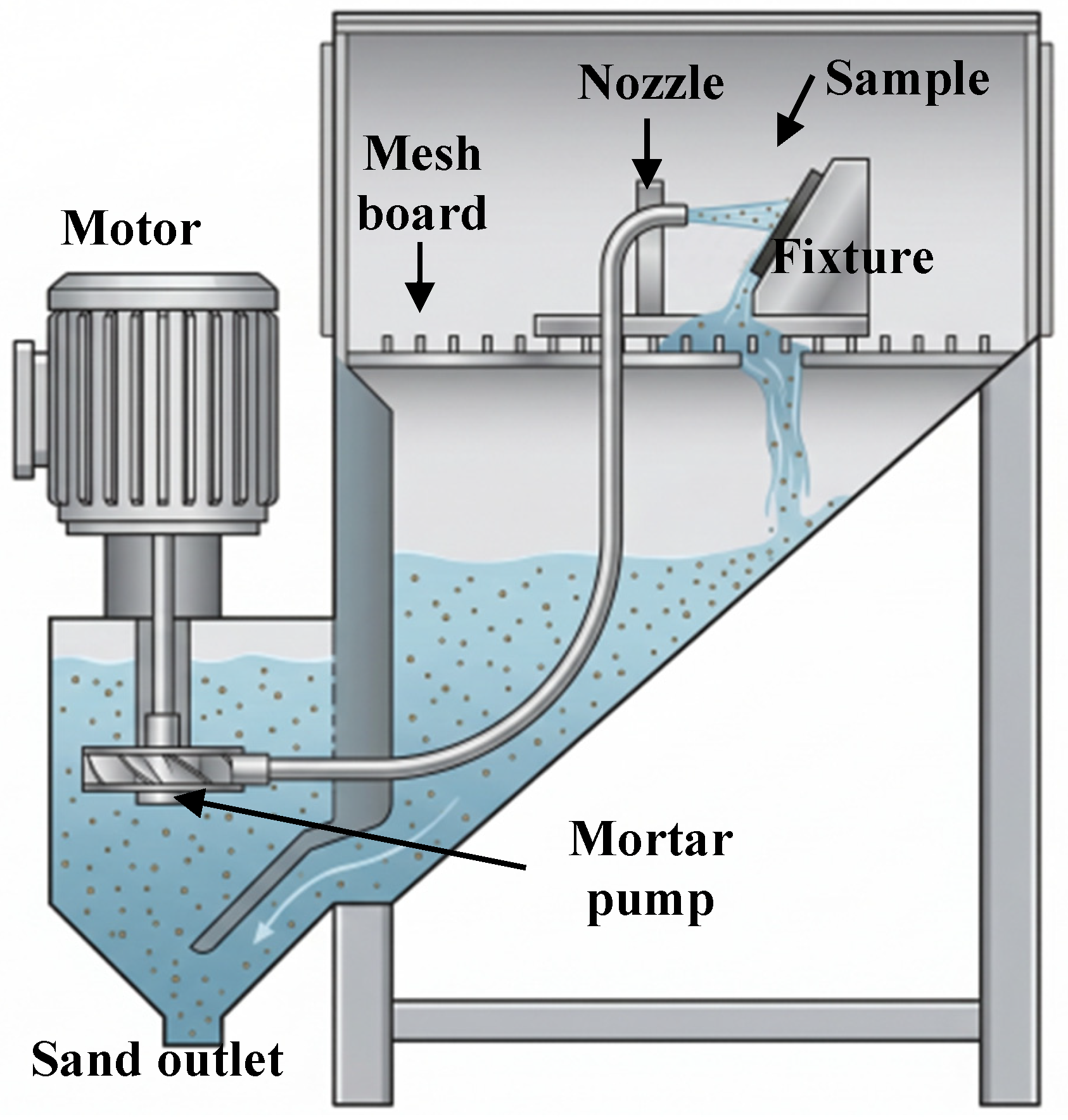
The slurry erosion behavior of the coatings was evaluated using a slurry-jet erosion apparatus. The slurry consisted of 1.5 kg of 325-mesh sand and 15 kg of water. The standoff distance between the nozzle and the specimen surface was approximately 25 mm. The impact angle was 30°, and the jet velocity was 95 ± 5 m s−1. A schematic diagram of the slurry erosion test setup is shown in Figure 3.
During the erosion test, the specimens were removed and weighed at intervals of 1.5 h. To reduce experimental error, each specimen was weighed three times at each interval, and the average value was used. After erosion testing, the eroded surface morphologies were examined by SEM. The specific erosion rate (Em) was calculated according to Equation (2).
E m = m t
where m is the mass loss (mg), t is the erosion duration (h).

2.7. Data Treatment and Repeatability

For the sliding wear and slurry erosion tests, repeated measurements were conducted for each sample condition, and the results are reported as average values with standard deviations. The friction coefficient curves were recorded directly during the wear tests, while the wear rates and erosion losses were calculated from the measured wear volume and mass-loss data, respectively.

3. Results

3.1. Phase Constitution of the Coatings

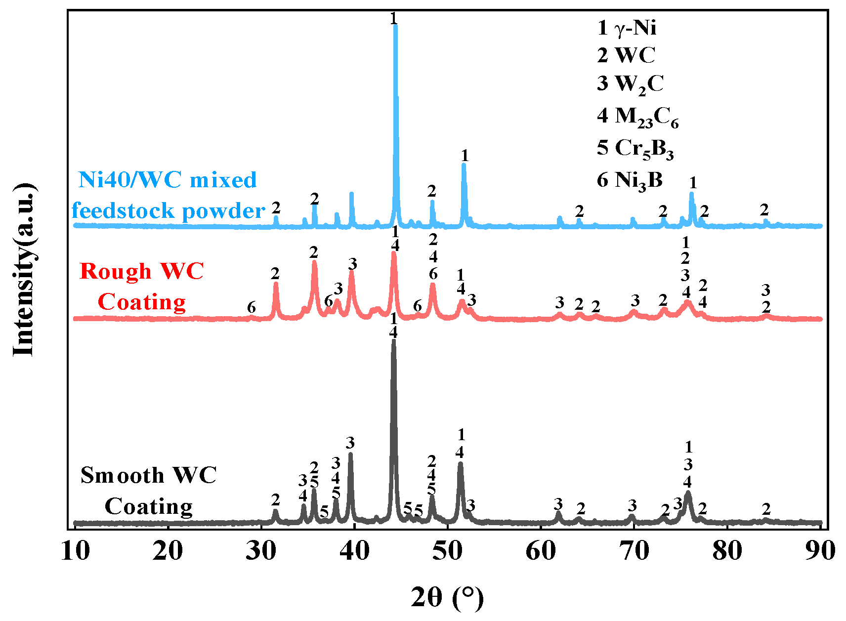
Figure 4 compares the XRD patterns of the feedstock powder mixture and the two laser-cladded coatings.
As shown in Figure 4, the feedstock powder mixture exhibited the characteristic diffraction peaks of Ni and WC. After laser cladding, both coatings exhibited diffraction peaks corresponding mainly to γ-Ni, WC, W2C, carbides, and borides.
Compared with the SWC, the RWC showed stronger diffraction peaks associated with W2C and carbide phases, whereas the SWC displayed a higher and sharper γ-Ni peak. The phase constituents identified for the two coatings were similar, while the relative peak intensities differed.

3.2. Cross-Sectional Microstructure of the Coatings

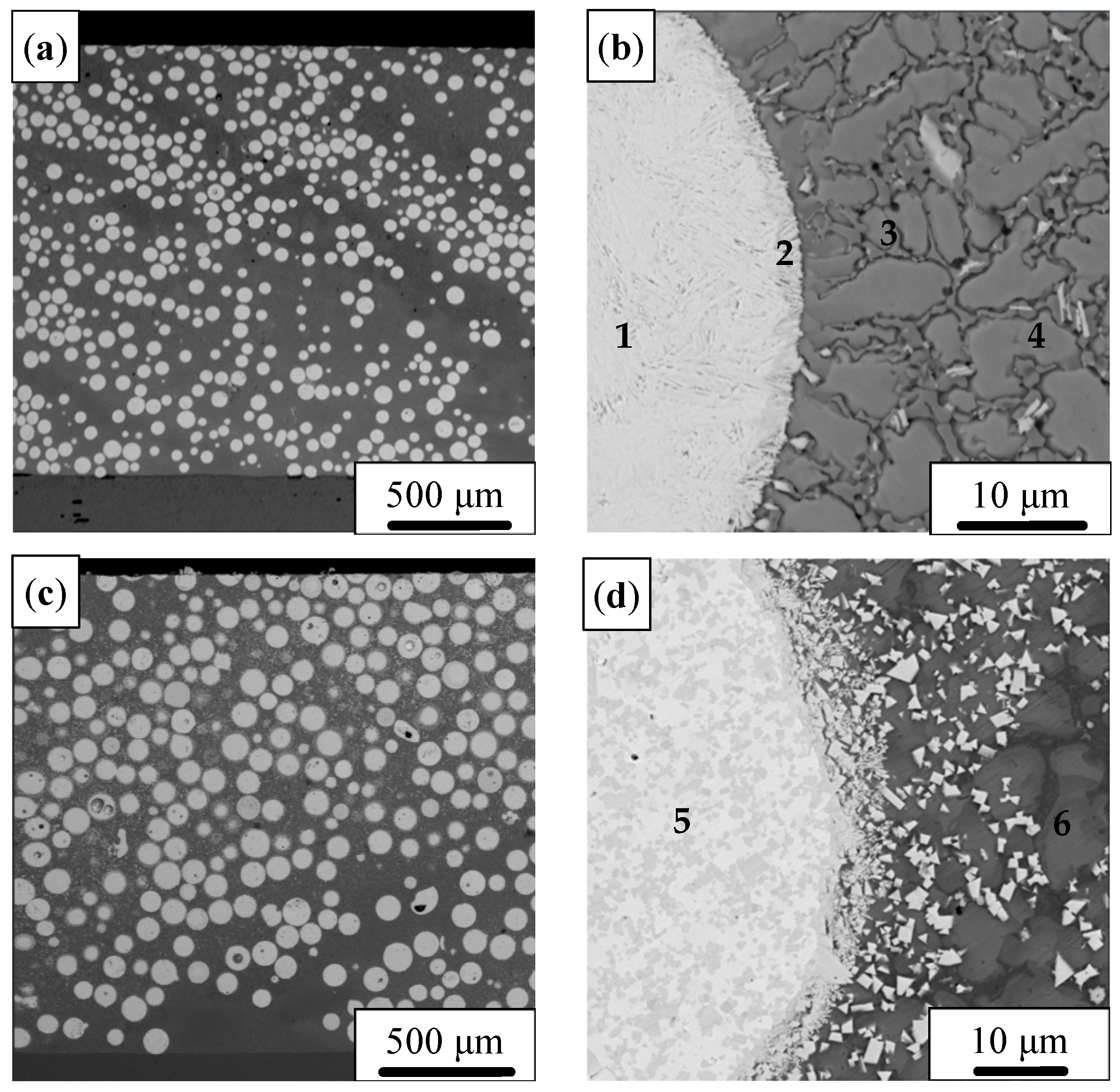
Figure 5 shows the cross-sectional microstructures of the two laser-cladded coatings at low and high magnifications.
As shown in Figure 5a,c, under the same cladding conditions, both coatings formed continuous clad layers with similar thicknesses. No macroscopic cracks were observed in either coating. Some pores were present in both coatings. The WC particles were distributed throughout the cladding layers, and no obvious sedimentation of WC particles was observed [17].
At higher magnification, as observed from Figure 5b,d, both coatings exhibited a dendritic microstructure in the matrix together with interdendritic eutectic constituents. A distinct interface could be observed between the retained WC particles and the surrounding matrix. In some regions, an alloyed reaction layer was visible around the WC particles. The EDS results for the selected regions marked in Figure 5 are summarized in Table 4.
From Table 4 and Figure 5b,d, it can be seen that Point 3 in Figure 5b was enriched in Ni with minor Cr and W, while Point 4 contained higher amounts of W and Cr than Point 3. Points 1 and 2, located inside the WC particle and near its outer region, showed different Ni and W contents. In Figure 5d, Point 5 was rich in W and C, and Point 6 contained Ni together with C, B, and W. These compositional differences confirm the coexistence of retained WC particles, matrix regions, and reaction products within the coatings [17,18].

3.3. Hardness of the Coatings

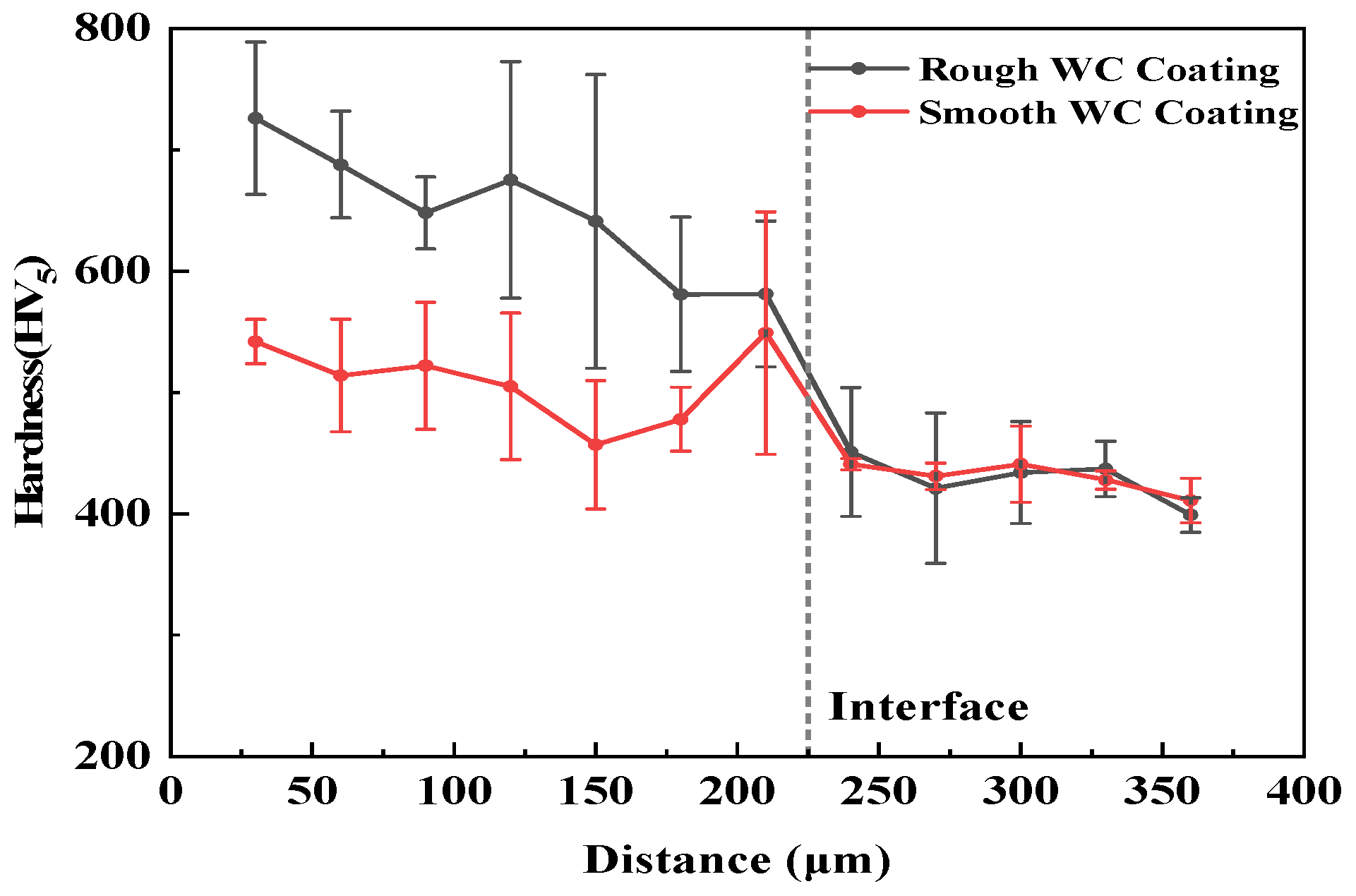
The Vickers hardness of the 0Cr13Ni5Mo substrate steel used in this study is typically between 250HV0.3 and 320HV0.3, and the hardness of silica sand used in the erosion test is about 1100HV. Figure 6 presents the cross-sectional microhardness distribution of the two coatings, measured at 30 μm intervals from the surface to the substrate over a total of 12 points. Table 5 summarizes the average hardness values of the WC particles, binder phase, and coatings.
As shown in Figure 6 and Table 5, both laser-cladded coatings exhibited significantly higher hardness than the substrate, confirming the reinforcing effect of the WC particles. The smooth spherical WC particles exhibited higher individual hardness than the rough spherical WC particles. In contrast, the binder phase in the RWC showed higher hardness than that in the SWC. Consequently, the RWC also exhibited higher overall hardness [17]. These results indicate that the hardness of the composite coating was governed more by binder-phase strengthening and particle–matrix cooperation than by the intrinsic hardness of the retained WC particles alone.

3.4. Water-Lubrication Sliding Test

3.4.1. Friction Coefficient and Wear Rate

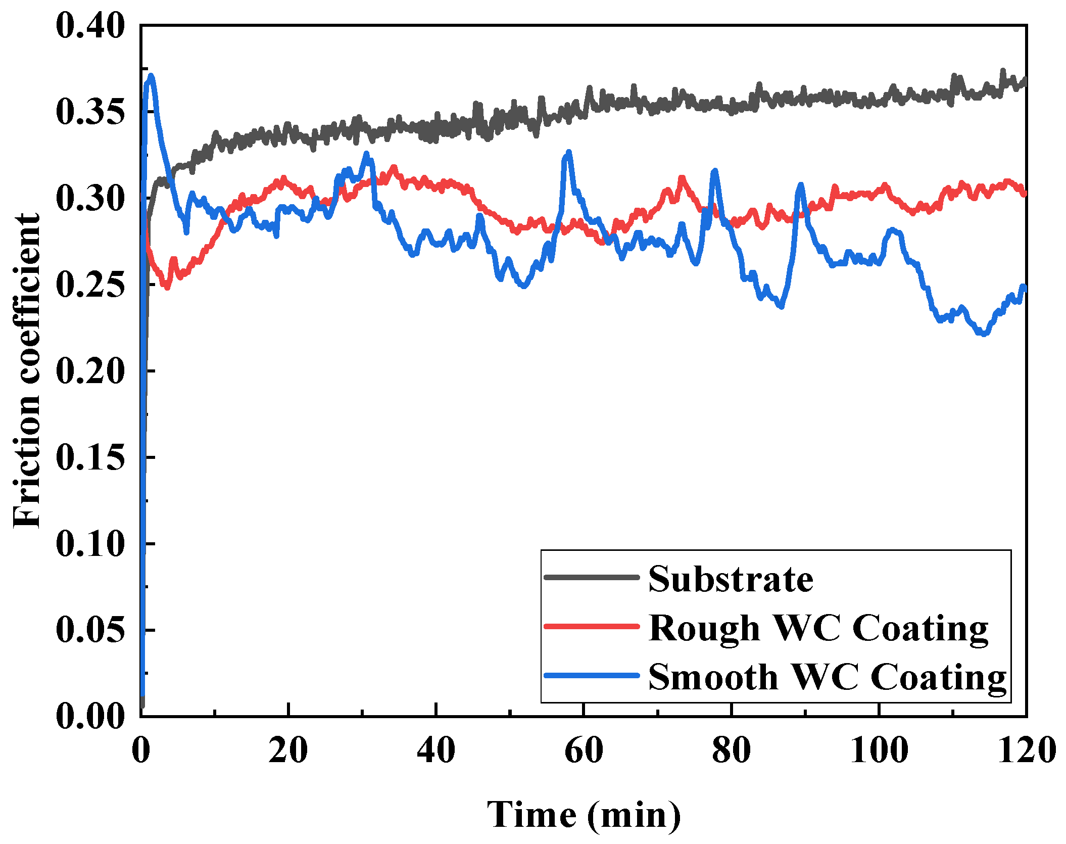
The friction coefficient curves under water-lubricated conditions are shown in Figure 7.
As shown in Figure 7, the friction coefficients of the substrate and both coatings remained relatively low and stable during most of the test period. The three samples also exhibited an initial transient stage followed by a relatively stable stage. The average friction coefficients and wear rates are listed in Table 6.
From Table 6, it is evident that under these lubricated conditions, the RWC (wear rate: 345.52 μm3·N−1·m−1) outperforms the SWC (517.08 μm3·N−1·m−1), with a reduction of about 33.2%. The friction coefficients of the two coatings become nearly identical (0.29 for RWC vs. 0.28 for SWC), both substantially lower than that of the substrate (0.35).

3.4.2. Worn Surface Morphology

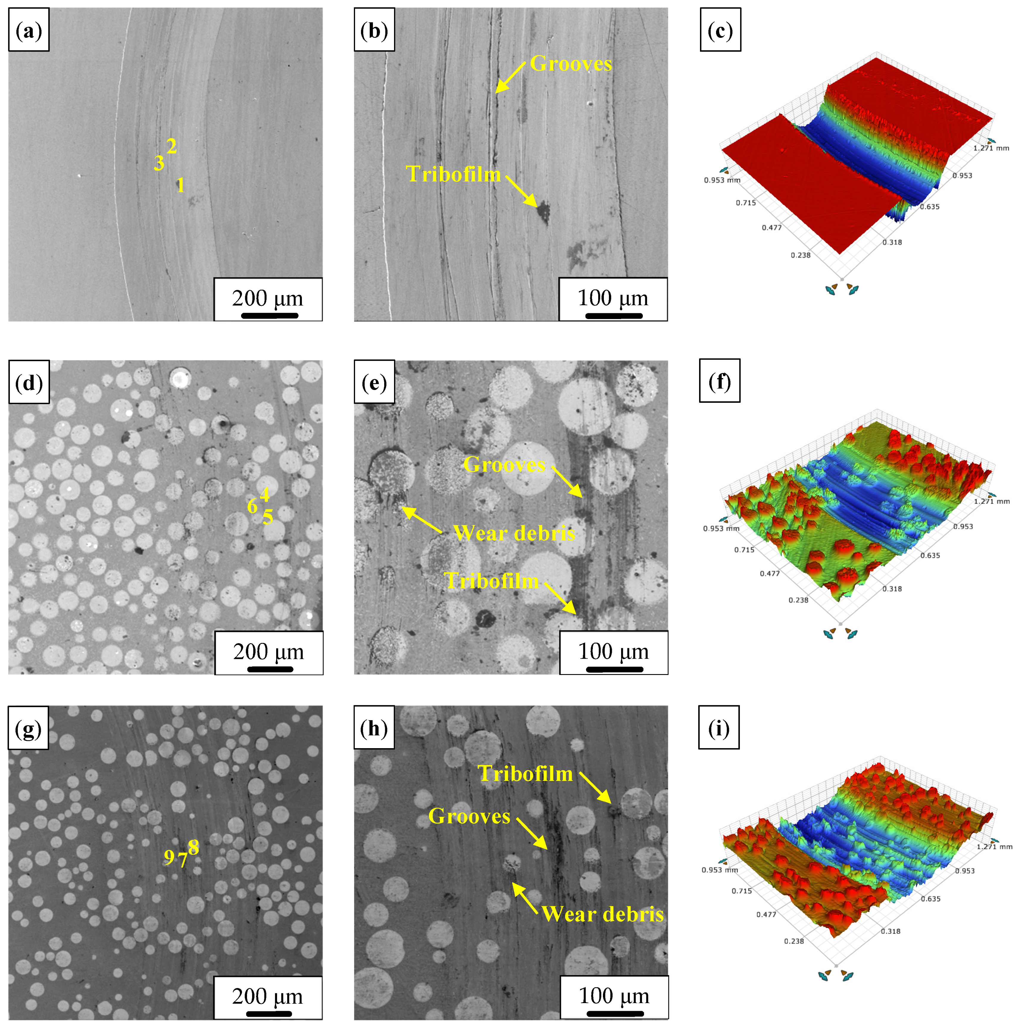
Figure 8 shows low and high magnification SEM images and 3D topography images of the wear tracks after water-lubricated sliding.
As shown in Figure 8, the worn surfaces of all three samples were smooth, indicating that water lubrication effectively mitigated surface damage. The RWC showed shallow grooves and local debris accumulation. The SWC showed more pronounced grooves, tribofilm discontinuity, and wear debris accumulation. Fractured WC particles were observed in the RWC, while the SWC showed exposed WC particles and local surface damage.
The substrate shows a deep, wide groove with pronounced edge pile-up. The RWC exhibits the shallowest and smoothest track with a flat-bottomed profile and no continuous transfer film, only sparse debris patches. The SWC shows an intermediate-depth, undulating track with discontinuous transfer film patches and exposed WC particles. These observations directly correlate with the wear resistance ranking: RWC > SWC > substrate, confirming that the RWC’s hard binder minimizes plastic deformation and suppresses transfer film instability. The EDS results for the selected positions in Figure 8 are listed in Table 7.
For the RWC (Positions 4–6 in Figure 8), the high W contents indicate exposed WC-rich regions with limited oxidation. For the SWC (Positions 7–9 in Figure 8), the coexistence of Ni-rich regions and W-rich regions suggests preferential exposure of the binder phase together with locally exposed WC particles [19].

3.5. Slurry Erosion Behavior

3.5.1. Erosion Rate

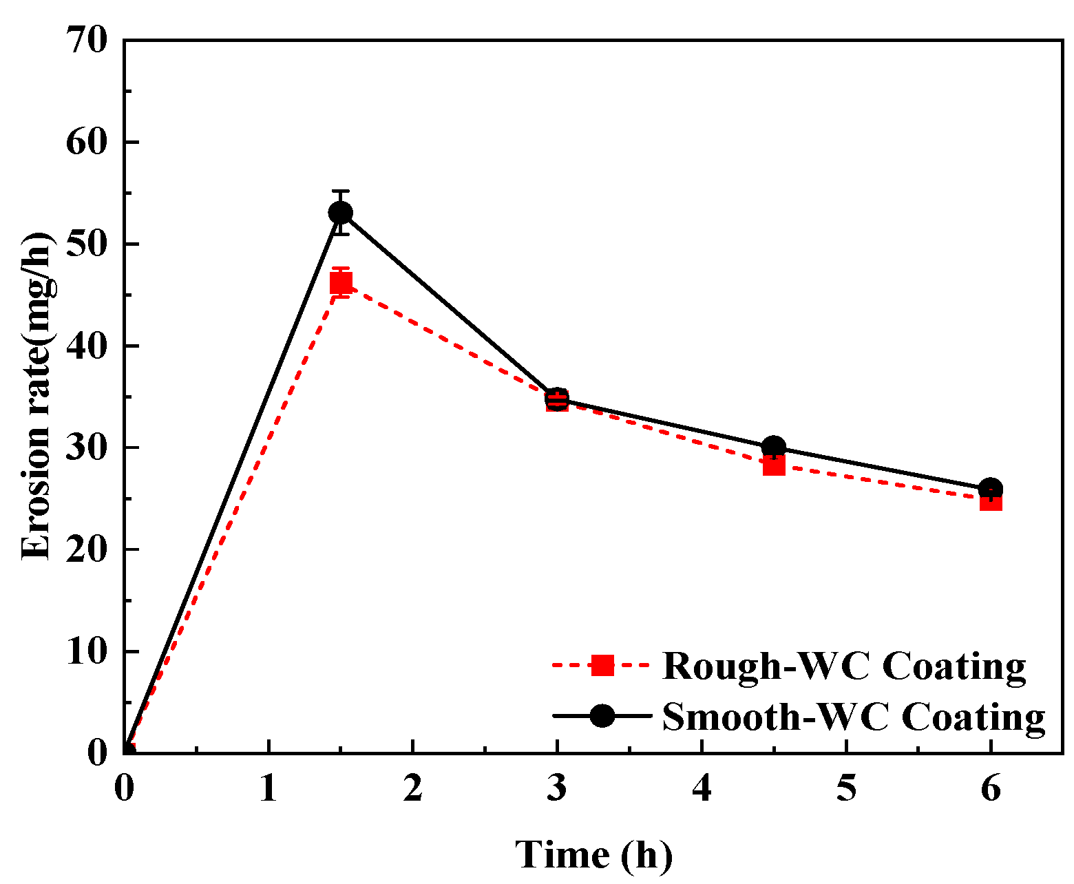
Because Pelton turbine buckets are typically subjected to low-angle particle impingement in service, the present study focused on slurry erosion at an impact angle of 30° [20]. It is worth noting that for hard and superhard coating materials, the most severe erosion damage generally occurs at normal impact (90°) rather than shallow angles [21,22]. However, the objective of the present study is not a universal ranking of coating erosion resistance but rather an application-oriented evaluation under service-relevant conditions. At 30° impact angle, micro-cutting and ploughing of the coating surface by erodent particles dominate the material removal mechanism, which closely resembles the actual wear pattern observed in Pelton turbine buckets exposed to sediment-laden water flows. Therefore, while 90° impact would provide a more severe test scenario, the selected 30° condition better represents the actual operating conditions of the target component. Figure 9 summarizes the erosion-rate evolution of the two coatings as a function of erosion time.
As shown in Figure 9, the erosion rate of both coatings reached a maximum at the initial stage and then gradually decreased with erosion time. At all test intervals, the RWC exhibited a lower erosion rate than the SWC, indicating slightly better slurry erosion resistance.

3.5.2. Eroded Surface Morphology

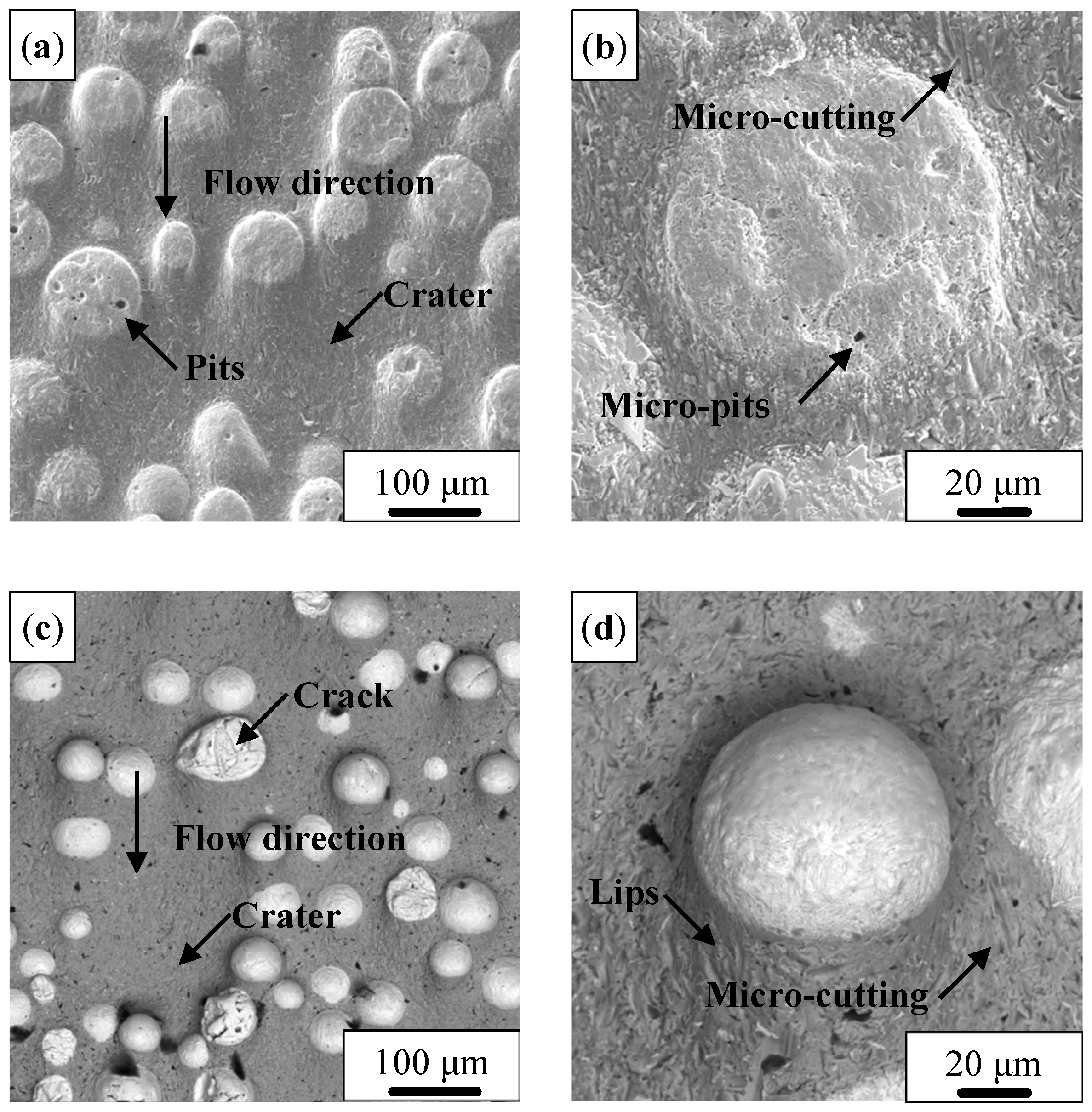
The surface morphologies after slurry erosion are shown in Figure 10.
As shown in Figure 10, both coatings exhibited eroded tracks along the flow direction. On the RWC, the eroded surface showed grooves, crater-like features, and local particle exposure. On the SWC, the eroded surface showed more pronounced grooves, lips, cracks, and exposed or damaged particles. At higher magnification, as shown in Figure 10, both coatings exhibited localized surface damage in the matrix regions as well as damage associated with the embedded WC particles. The RWC showed a comparatively smoother eroded profile, whereas the SWC displayed stronger surface relief and more obvious local damage features.

4. Discussion

4.1. Effect of WC Particle Morphology on Dissolution Behavior During Laser Cladding

The present results indicate that WC particle morphology plays an important role in determining the final microstructure and performance of the laser-cladded Ni-based WC coatings. At first glance, this conclusion may appear counterintuitive, because the rough spherical WC particles used in this study possess lower intrinsic hardness and strength than the smooth spherical WC particles produced by plasma spheroidization. If the coating performance were governed only by the hardness of the ceramic reinforcement itself, the SWC should have shown better wear and erosion resistance. However, the experimental results revealed the opposite trend, indicating that the dominant factor is not the intrinsic hardness of the individual WC particles, but their interaction with the molten pool and the resulting evolution of the binder phase during laser cladding [23].
This difference is likely related to the distinct structural characteristics of the two WC powders. As shown in Figure 1, the rough spherical WC particles were formed by the agglomeration and sintering of fine WC particles. Such particles generally have a rougher surface, a more heterogeneous internal structure, and a larger effective interfacial area in contact with the molten Ni-based alloy during cladding. As a result, they are more susceptible to partial dissolution under laser irradiation. By contrast, the smooth spherical WC particles prepared by plasma spheroidization are denser and have smoother surfaces, which reduces their dissolution tendency during the short high-temperature exposure in the molten pool [24].
The stronger dissolution of rough WC has two important consequences. First, more W and C can enter the surrounding Ni-based binder phase, which promotes solid-solution strengthening and the formation of secondary hard phases such as W2C and metallic carbides. Second, the local chemical enrichment around the partially dissolved WC particles changes the solidification behavior of the binder phase and contributes to a harder microstructural framework. From Figure 4 and Figure 5, as well as Table 4, it can be seen that the RWC showed stronger diffraction peaks associated with W2C and carbide phases, together with distinct compositional differences between retained WC particles, matrix regions, and reaction products. Therefore, although the rough WC particles themselves are mechanically inferior to the smooth ones, they provide a stronger strengthening effect on the matrix during cladding. This matrix strengthening effect is the key reason why the RWC exhibited higher binder hardness and higher overall coating hardness [25].
In contrast, the smooth WC particles remained more intact during cladding. Their higher intrinsic hardness was preserved to a greater extent, but the amount of W and C transferred into the binder phase was lower. Consequently, the binder phase in the SWC experienced less strengthening and remained relatively soft. This difference in matrix response is more important to the final coating performance than the hardness difference between the retained WC particles themselves.

4.2. Relationship Between Binder-Phase Strengthening and Coating Hardness

The hardness results further support the above interpretation. Table 5 shows that the smooth spherical WC particles showed higher individual hardness than the rough spherical WC particles, which is consistent with their dense structure and higher intrinsic mechanical integrity. However, the coating reinforced with rough WC exhibited a harder binder phase and a higher overall hardness. This apparent contradiction indicates that the hardness of the coating cannot be evaluated simply by measuring the hardness of the retained WC particles [24].
For laser-cladded Ni-based WC coatings, the macroscopic hardness reflects the combined contribution of the retained carbide particles, the hardness of the metallic binder phase, the quantity and distribution of secondary hard phases, and the effectiveness of particle–matrix cooperation. A likely reason is that in the RWC, the enhanced dissolution of WC introduced more strengthening species into the Ni-based binder, thereby increasing its resistance to indentation and plastic deformation. The higher binder hardness also means that the matrix can better constrain the embedded hard particles and improve the integrity of the composite coating under external loading. This explains why the RWC achieved a higher overall hardness despite containing WC particles with lower intrinsic hardness [26].
The opposite situation occurred in the SWC. Although its WC particles were harder, the surrounding binder phase was softer and therefore less effective in supporting these particles during mechanical loading. Once the matrix becomes the weak part of the coating, the benefit of very hard ceramic particles is greatly reduced. In other words, the hardness mismatch between a very hard particle and a relatively soft binder may even become detrimental during wear and erosion, because the soft matrix is preferentially removed and the hard particles then lose support. Therefore, these results suggest that the higher overall hardness of the RWC is fully consistent with the observed trend in sliding wear and slurry erosion resistance.

4.3. Wear Behavior and Mechanism Under Water-Lubricated Sliding Conditions

Under water-lubricated conditions, both coatings exhibited low friction coefficients. This stems from the cooling and lubricating effect of the water film, which reduces direct contact between the asperities and limits tribo-oxidation. For the smooth WC coating (SWC), the relatively low density of hard phases in its binder phase leads to less scratching of the alumina ball, resulting in a slightly lower friction coefficient compared to the RWC. In contrast, the rough WC coating (RWC) contains a higher fraction of fine hard particles in its binder phase; these particles act as micro-cutting tools on the ceramic ball, making the ball surface rougher and resulting in a relatively higher friction coefficient. Nevertheless, the RWC still exhibited significantly lower wear loss than the SWC under water lubrication [25].
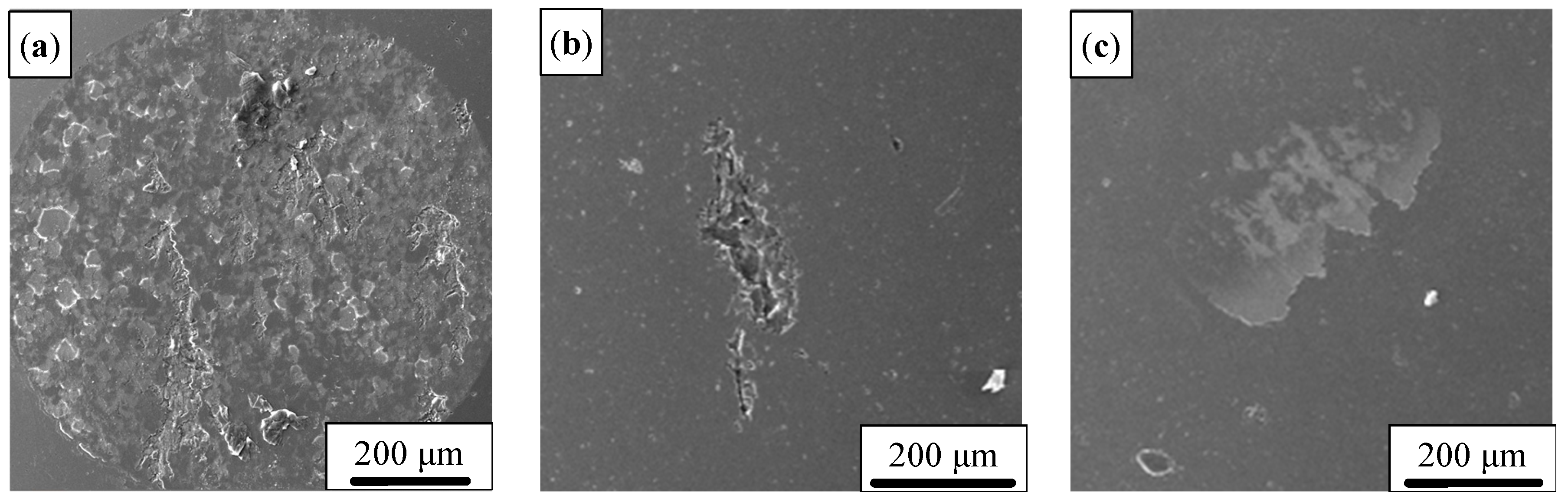
The SEM images of the Al2O3 ball wear scars after sliding against different surfaces under water-lubricated conditions is shown in Figure 11.
SEM observations of the alumina counterface balls (Figure 11) support these findings. The ball run against the RWC (Figure 11b) shows a more compact wear scar with numerous fine, consistent with the micro-cutting effect of the hard binder-phase particles. Conversely, the ball from the SWC (Figure 11c) displays a smoother overall surface with shallower grooves, correlating with the lower hardness of its binder phase [26].
All three counterface balls showed limited wear scar formation under water-lubricated conditions. The ball slid against the RWC exhibited a more localized scar with visible scratches, whereas the ball slid against the SWC showed a relatively smoother scar morphology, which corroborates the lowest friction coefficient of the SWC under water.
It is worth mentioning that, the SWC exhibits poorer wear resistance than the RWC, primarily due to its softer binder phase, which remains the weak link. Although the water film reduces the overall wear rate, repeated sliding progressively removes the binder. Once matrix support weakens, the smooth WC particles become more prone to detachment, and these dislodged hard particles can induce local three-body abrasion, further damaging the surface. In contrast, the RWC—with its harder binder providing stable support for both embedded WC particles and secondary hard phases—retains better surface integrity. The reduced shear stress under water lubrication slows binder removal, preserving the composite structure and thereby maintaining good wear resistance.
To further elucidate the wear mechanisms: The rough WC coating (RWC) exhibits a two-body abrasion mechanism dominated by micro-cutting. Fine hard particles in its harder binder act as fixed micro-edges, ploughing the counterface while the strong binder securely anchors WC particles, preventing early pull-out. Consequently, the RWC shows low wear loss despite a slightly higher friction coefficient. In contrast, the smooth WC coating (SWC) undergoes a binder-mediated wear process. The softer binder softens and smears under repeated sliding, weakening the support for WC particles. Once detached, these hard particles roll between the surfaces, inducing three-body abrasion that accelerates material removal. This explains the higher wear loss of the SWC, notwithstanding its lower friction coefficient. The rough, angular morphology of WC particles in the RWC promotes mechanical interlocking with the binder, enhancing interfacial cohesion [26,27]; the smooth WC particles in the SWC lack such bonding, making them prone to detachment [25,28]. These mechanisms highlight that both binder phase properties and WC particle morphology govern the water-lubricated wear behavior.
These observations confirm that the morphology of WC particles strongly influences the coating’s microstructure and its performance under aqueous conditions. The advantage of the RWC stems from matrix strengthening induced by the dissolution of rough WC particles, a robust mechanism that enhances coating integrity during water-lubricated wear. The critical role of the binder phase in governing the wear behavior of WC-based coatings under such conditions has been systematically examined in recent literature [27,28].

4.4. Mechanism of Improved Slurry Erosion Resistance in the RWC

The same microstructural argument can be used to explain the slurry erosion behavior. During slurry erosion by SiO2 sand particles, the coating surface is subjected to repeated high-speed impacts and cutting actions [29]. Under the present test condition, especially at a low impact angle, micro-cutting of the exposed surface plays a major role [27,29]. In such a process, the resistance of the metallic binder phase to cutting and material removal is crucial, because the binder phase is the component that holds the carbide particles in place.
In the RWC, the binder phase was strengthened by the greater dissolution of WC during laser cladding. This harder binder could better withstand the cutting action of the incoming SiO2 particles, thereby reducing preferential material removal from around the carbide particles [26]. As a result, the coating surface remained more stable, and the carbide particles could continue to contribute to erosion resistance instead of being prematurely detached [28]. Although the rough WC particles are intrinsically less hard than the smooth ones, they are embedded in a stronger and more erosion-resistant matrix, which leads to superior overall slurry erosion performance [27]. Figure 9 shows that the RWC maintained a lower erosion rate than the SWC throughout the erosion test.
In the SWC, the softer binder phase was more vulnerable to erosive cutting. Once the binder was preferentially removed, the smooth WC particles became exposed and unsupported. Because these particles were no longer firmly anchored, they could be dislodged under repeated impact by the slurry particles. Their detachment then accelerated surface damage and increased material loss. Therefore, the inferior erosion resistance of the SWC is not due to insufficient hardness of the carbide particles, but rather to insufficient hardness and load-bearing capacity of the binder phase [29]. As shown in Figure 10, the SWC displayed more pronounced grooves, lips, cracks, debris accumulation, and exposed or damaged particles after slurry erosion.
Another important point is that erosion resistance in this type of composite coating depends on the balance between the erosion rates of the hard phase and the binder phase. In the RWC, the higher binder hardness narrows the performance gap between the two constituents, which helps maintain a relatively stable surface profile during erosion [27,29]. In the SWC, the large difference between a very hard WC particle and a relatively soft binder promotes differential erosion, surface roughening, and particle exposure, all of which make the coating more vulnerable to continued slurry attack. This interpretation is in good agreement with the observed erosion morphologies and mass-loss results shown in Figure 9 and Figure 10.
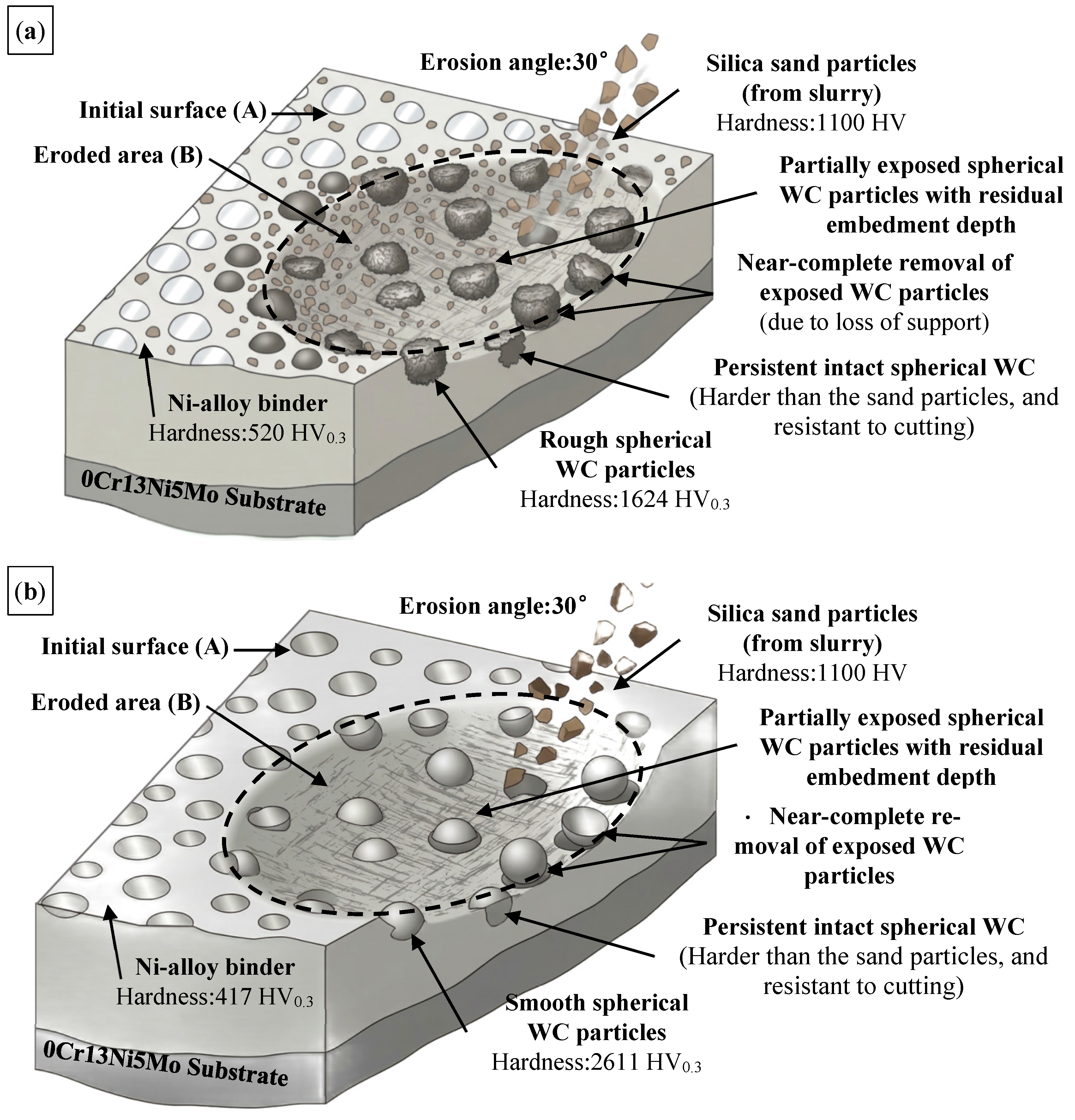
A schematic diagram illustrating the slurry erosion mechanisms of the two coatings is shown in Figure 12.
As shown in Figure 12, the RWC is characterized by a more balanced removal behavior between the hard phase and the binder phase, whereas the SWC exhibits a larger difference in phase removal behavior and stronger surface relief development during erosion.

4.5. Unified Understanding of the Role of Rough WC in This Coating System

Taken together, the present results suggest that rough spherical WC should not be evaluated only from the perspective of individual particle hardness. In this laser-cladded Ni-based coating system, the primary role of the WC particles is not merely to remain intact as isolated ultra-hard reinforcements, but also to interact with the molten binder phase and modify its composition, hardness, and load-bearing capability. From this viewpoint, rough WC is actually more effective than smooth WC, because its stronger dissolution tendency produces a harder and more supportive matrix.
This interpretation also explains why the same trend was observed in coating hardness, water-lubricated wear, and slurry erosion resistance. From Table 5 and Table 6, as well as Figure 8, Figure 9 and Figure 10, it can be found that the decisive factor in all these cases is whether the binder phase can resist removal and continue to support the hard particles during service. Once the binder phase fails, the hard particles can no longer function effectively, no matter how high their intrinsic hardness may be. Therefore, for the present laser-cladded Ni40–WC coating system, the superior performance of the RWC arises from enhanced binder-phase strengthening rather than from superior properties of the WC particles themselves.
From an application perspective, this finding is important for the design of protective coatings for hydraulic components. For Pelton turbine buckets exposed to sand-laden water, a coating with stronger binder-phase resistance is advantageous for mitigating slurry erosion. For sliding surfaces, a harder and more supportive matrix improves resistance to friction-induced material removal. Therefore, the use of rough spherical WC prepared by spray granulation and sintering appears to be a promising strategy for improving the durability of laser-cladded Ni-based coatings in hydraulic machinery.

5. Conclusions

In this study, Ni-based WC composite coatings reinforced with rough spherical WC and smooth spherical WC were prepared on 0Cr13Ni5Mo steel by laser cladding under the same optimized conditions. Based on the comparative analysis of phase constitution, microstructure, hardness, water-lubricated sliding wear behavior, and slurry erosion resistance, the following conclusions can be drawn:
(1)
Both coatings consisted mainly of γ-Ni, residual WC, W2C, carbides, and borides. Under the same cladding conditions, rough spherical WC dissolved more readily than smooth spherical WC, promoting stronger binder-phase alloying and matrix strengthening.
(2)
Although the rough WC particles were softer than the smooth WC particles (1624 ± 566 vs. 2611 ± 438 HV0.3), the RWC showed a higher binder-phase hardness (520 ± 31 vs. 417 ± 26 HV0.3) and a higher overall coating hardness (742 ± 76 vs. 506 ± 94 HV5), corresponding to increases of about 25% and 47%, respectively.
(3)
The RWC exhibited superior sliding wear resistance under water lubrication. Its specific wear rate was about 33.2% lower than that of the SWC. This improved performance is attributed to the strengthened binder phase, which effectively anchored the hard particles and provided more stable support during the sliding process.
(4)
The RWC also maintained lower slurry erosion rates and milder erosion damage than the SWC throughout the testing period. Therefore, for the Ni40–WC laser-cladded coating system, tailoring WC particle morphology is more effective than relying solely on the intrinsic hardness of WC reinforcements. Rough spherical WC is the more suitable reinforcement for hydraulic components requiring both wear and slurry-erosion resistance.

Author Contributions

Conceptualization, Q.W. and J.L.; methodology, Q.W. and J.L.; software, Q.W. and R.Z.; validation, Q.W., J.L. and S.W.; formal analysis, N.L.; investigation, J.L.; resources, K.Y.; data curation, Q.W. and J.L.; writing—original draft preparation, J.L.; writing—review and editing, Q.W., C.S.R. and J.L.; visualization, J.L.; supervision, R.Z.; project administration, Q.W.; funding acquisition, Q.W. All authors have read and agreed to the published version of the manuscript.

Funding

This work was financially supported by the State Key Laboratory Project of China Minmetals Corporation (No. 2025GZYJ01).

Data Availability Statement

The original contributions presented in this study are included in the article. Further inquiries can be directed to the corresponding author.

Conflicts of Interest

Author Ruilin Zeng, Shequan Wang, Ninghua Long, Kongming Yan were employed by the company Zhuzhou Cemented Carbide Group Co. Ltd. The remaining authors declare that the research was conducted in the absence of any commercial or financial relationships that could be construed as a potential conflict of interest.

References

  1. Kumar, R.; Bhandari, D.; Goyal, K. Slurry erosion behaviour of HVOF-sprayed coatings on hydro turbine steel: A review. IOP Conf. Ser. Mater. Sci. Eng. 2021, 1033, 012064. [Google Scholar] [CrossRef]
  2. Bolelli, G.; Berger, L.M.; Börner, T.; Koivuluoto, H.; Lusvarghi, L.; Lyphout, C.; Vuoristo, P. Tribology of HVOF- and HVAF-sprayed WC–10Co4Cr hardmetal coatings: A comparative assessment. Surf. Coat. Technol. 2015, 265, 125–144. [Google Scholar] [CrossRef]
  3. Jiang, D.; Wang, G.; Dong, W.; Hong, X.; Guo, C. Recent advance on metal carbides reinforced laser cladding coatings. Molecules 2025, 30, 1820. [Google Scholar] [CrossRef] [PubMed]
  4. Yang, J.; Peng, H.; Zhao, K.; Fan, C.; Luo, D.; Wu, Q.; Zhang, Z. Research on the microstructure and properties of Stellite6/WC composite coatings via laser cladding. JOM 2024, 76, 3769–3782. [Google Scholar] [CrossRef]
  5. Li, D.; Zhang, J.; Wang, C.; Fan, H. Microstructure and properties of laser cladding WC/Ni composite coatings with different compositions. Matéria 2025, 30, e20240790. [Google Scholar] [CrossRef]
  6. Bartkowski, D.; Kinal, G. Microstructure and wear resistance of Stellite-6/WC MMC coatings produced by laser cladding using Yb:YAG disk laser. Int. J. Refract. Met. Hard Mater. 2016, 58, 157–164. [Google Scholar] [CrossRef]
  7. Liu, Y.; Gu, X.; Lou, C.; Kang, L.; Hou, Q.; Ma, C. Influence of WC ceramic particles on structures and properties of laser cladding Ni50-WC coatings. J. Mater. Res. Technol. 2023, 26, 14–21. [Google Scholar] [CrossRef]
  8. Li, X.; Zhang, S.; Liu, W.; Pang, X.; Tong, Y.; Zhang, M.; Zhang, J.; Wang, K. Effect of WC content on the wear and corrosion properties of oscillating laser-cladding-produced nickel-based coating. Coatings 2023, 13, 1614. [Google Scholar] [CrossRef]
  9. Liu, X.; Meng, L.; Zeng, X.; Zhu, B.; Cao, J.; Wei, K.; Hu, Q. Study on the microstructure, mechanical properties and cavitation erosion resistance of 17-4PH alloy coatings fabricated by high power laser cladding. Surf. Coat. Technol. 2024, 494, 131451. [Google Scholar] [CrossRef]
  10. Qi, C.; Zhan, X.; Gao, Q.; Liu, L.; Song, Y.; Li, Y. The influence of the pre-placed powder layers on the morphology, microscopic characteristics and microhardness of Ti-6Al-4V/WC MMC coatings during laser cladding. Opt. Laser Technol. 2019, 119, 105572. [Google Scholar] [CrossRef]
  11. Khodabakhshi, A.; Eslami, A.; Ashrafizadeh, F.; Mendez, P. Microstructure, Erosion Performance, and Wear Resistance of Laser-Claded NiCrBSi-WC Composite Coatings. Metall. Mater. Trans. A 2025, 56, 2005–2020. [Google Scholar] [CrossRef]
  12. Chen, Y.; Huang, X.; Jiang, J.; Lian, G.; Chen, C. Study on the Effect of Rare Earth Oxide Addition on the Microstructure and Properties of Ni60/WC-Ni Coatings Prepared by Laser Cladding. Materials 2023, 16, 7263. [Google Scholar] [CrossRef]
  13. Li, Y.; Gao, Q.; Guan, X.; Tian, F.; Li, B.; Zhan, X. Effect of WC on the microstructure and wear resistance of Invar-WC coatings prepared by laser fusion cladding. J. Mater. Res. Technol. 2025, 34, 2285–2297. [Google Scholar] [CrossRef]
  14. Wang, X.; Zhu, L.; Zhou, Z.; Liu, G.; Liu, E.; Zeng, Z.; Wu, X. Tribological properties of WC-reinforced Ni-based coatings under different lubricating conditions. J. Therm. Spray. Technol. 2015, 24, 1323–1332. [Google Scholar] [CrossRef]
  15. Domitner, J.; Silvayeh, Z.; Buzolin, R.H.; Krisam, S.; Achterhold, K.; Povoden-Karadeniz, E.; Sommitsch, C.; Mayr, P. Microstructure characterization of nickel matrix composite reinforced with tungsten carbide particles and produced by laser cladding. Adv. Eng. Mater. 2022, 24, 2200463. [Google Scholar] [CrossRef]
  16. Hu, Z.; Li, Y.; Lu, B.; Tan, N.; Cai, L.; Yong, Q. Effect of WC content on microstructure and properties of high-speed laser cladding Ni-based coating. Opt. Laser Technol. 2022, 155, 108449. [Google Scholar] [CrossRef]
  17. Liu, E.; Zhang, J.; Liu, Z.; Du, S.; Cai, H.; Du, H.; Gao, Z. Study on melting–precipitation evolution of WC in Ni/WC-12Co coating during laser cladding and tribological properties. J. Mater. Eng. Perform. 2023, 32, 4968–4985. [Google Scholar] [CrossRef]
  18. Lin, G.; Cai, Z.; Lu, B.; Gu, L.; Wang, Y.; Yan, X.; Qiu, H.; Guo, J.; Dong, Z.; Li, F. Enhanced wear resistance of laser cladded WC-Ni composite coatings by picosecond laser surface texturing. Tribol. Int. 2025, 204, 110517. [Google Scholar] [CrossRef]
  19. Kim, G.; Kim, Y.-C.; Cho, J.-E.; Yim, C.-H.; Yun, D.-S.; Lee, T.-G.; Park, N.-K.; Chung, R.-H.; Hong, D.-G. Microstructural evolution, hardness and wear resistance of WC-Co-Ni composite coatings fabricated by laser cladding. Materials 2024, 17, 2116. [Google Scholar] [CrossRef]
  20. Singh, S.; Farwaha, H.S.; Kumar, R.; Ariffin, I.A.; Beemkumar, N.; Grewal, J.S.; Singh, I.; Bhowmik, A.; Mbasso, W.F. Slurry erosion performance of WC-Co and Cr3C2-NiCr coatings on hydro turbine steel: Optimization and modelling under variable operational conditions. Oxf. Open Mater. Sci. 2025, 5, itaf008. [Google Scholar] [CrossRef]
  21. Liu, J.; Chen, T.; Yuan, C.; Bai, X. Performance analysis of cavitation erosion resistance and corrosion behavior of HVOF-sprayed WC-10Co-4Cr, WC-12Co, and Cr3C2-NiCr coatings. J. Therm. Spray. Technol. 2020, 29, 798–810. [Google Scholar] [CrossRef]
  22. Behera, N.; Medabalimi, S.; Ramesh, M.R. Effect of impact angles and temperatures on the solid particle erosion behavior of HVOF sprayed WC-Co/NiCr/Mo and Cr3C2-CoNiCrAlY coatings. J. Therm. Spray. Technol. 2023, 32, 2411–2425. [Google Scholar] [CrossRef]
  23. Liu, L.; Zhang, K.; Wang, Y. Baffle effect of exposed WC particles in the clearance on slurry erosion behavior of cemented carbide surface. Mater. Today Commun. 2024, 39, 109071. [Google Scholar] [CrossRef]
  24. Deng, T. Erosive wear mechanisms of materials—A review of understanding and progresses. Materials 2025, 18, 1615. [Google Scholar] [CrossRef] [PubMed]
  25. Wheeler, D.W.; Wood, R.J.K. Erosion of hard surface coatings for use in offshore gate valves. Wear 2005, 258, 526–536. [Google Scholar] [CrossRef]
  26. Singh, S.; Bansal, A.; Kumar, P.; Goyal, D.K. Slurry erosion behavior of Hogonas+50% WC cladded SS304 steel prepared using variable laser cladding parameters. Int. J. Refract. Met. Hard Mater. 2023, 115, 106326. [Google Scholar] [CrossRef]
  27. Liang, F.; Li, K.; Shi, W.; Zhu, Z.; He, Q. Effect of CeO2 addition on laser cladding Ni-based/WC composite coatings. Laser Technol. 2024, 48, 542–548. [Google Scholar] [CrossRef]
  28. Wang, J.; Liu, Y.; Zhang, X.; Zhang, Y.; Chen, Y.; Zhu, L.; Zhou, M. Corrosion-erosion behavior and mechanism of CuMo co-doped CoCrFeNi high-entropy alloy coating prepared by directed energy deposition. Surf. Coat. Technol. 2022, 451, 129055. [Google Scholar] [CrossRef]
  29. Singh, G.; Jain, P. Computational and experimental comparison of coated and uncoated pump impeller steel using the Taguchi and ANN approach. Eng. Comput. 2025, 42, 1751–1770. [Google Scholar] [CrossRef]
Figure 1. SEM morphologies and EDS spectra of the Ni-based alloy and two WC powders: (a,e) Ni40, (b) smooth spherical WC and (c,d,f) rough spherical WC.
Lubricants 14 00215 g001aLubricants 14 00215 g001b
Figure 2. Schematic illustration of the water-lubricated sliding wear test.
Lubricants 14 00215 g002
Figure 3. Schematic illustration of the slurry erosion test setup.
Lubricants 14 00215 g003
Figure 4. XRD patterns of Ni40/WC feedstock powder mixture, RWC, SWC.
Lubricants 14 00215 g004
Figure 5. Cross-sectional microstructures of the laser-cladded coatings: (a,b) SWC and (c,d) RWC.
Lubricants 14 00215 g005
Figure 6. Hardness gradient of the laser-cladded coatings.
Lubricants 14 00215 g006
Figure 7. Friction coefficient curves of the substrate and coatings under water lubrication test conditions.
Lubricants 14 00215 g007
Figure 8. Low and high-magnification SEM images of the wear tracks and 3D topography images after water-lubricated sliding: (ac) substrate, (df) RWC, and (gi) SWC.
Lubricants 14 00215 g008
Figure 9. Erosion rate of the coatings at an impact angle of 30°.
Lubricants 14 00215 g009
Figure 10. Surface morphologies of the coatings after slurry erosion: (a,b) RWC and (c,d) SWC.
Lubricants 14 00215 g010
Figure 11. SEM images of wear scars on the Al2O3 ball after sliding on (a) substrate, (b) RWC, and (c) SWC under water-lubricated conditions.
Lubricants 14 00215 g011
Figure 12. Schematic illustration of the slurry erosion mechanisms at an impact angle of 30°: (a) RWC and (b) SWC.
Lubricants 14 00215 g012
Table 1. Nominal chemical composition of 0Cr13Ni5Mo steel (wt.%).
ElementCrNiMoSiCFe
Content1350.5–1.00.80.03balance
Table 2. Nominal chemical composition of Ni40 powder (wt.%).
ElementCrFeBSiCNi
Content1052.530.3balance
Table 3. Laser cladding parameters used in this study.
Cladding
Power
Spot
Diameter
Movement
Speed
Overlap
Ratio
Substrate Preheat Temperature
1.5 kW7 mm30 mm/s50%450 °C
Table 4. EDS results for the selected regions in Figure 5 (at.%).
PositionNiCrWCBSi
1//15.884.2//
23.1/14.782.2//
372.34.01.622.1//
435.611.67.045.9//
50.2/3.694.61.7/
618.81.00.633.844.81.2
Table 5. Average hardness values of WC particles, binder phase, and coatings.
WC Coating CategoriesRegionHardness
Rough WC coatingWC particles1624 ± 566 (HV0.3)
Binder phase520 ± 31 (HV0.3)
Average coating hardness (cross-sectional)742 ± 76 (HV5)
Smooth WC coatingWC particles2611 ± 438 (HV0.3)
Binder phase417 ± 26 (HV0.3)
Average coating hardness (cross-sectional)506 ± 94 (HV5)
Table 6. Specific wear rate and average friction coefficient of the substrate and coatings under water-lubricated sliding conditions.
SampleSpecific Wear Rate (μm3·N−1·m−1)Average Friction Coefficient
Substrate1679.08 ± 322.140.35 ± 0.0221
RWC345.52 ± 64.210.29 ± 0.0133
SWC517.08 ± 32.960.28 ± 0.0275
Table 7. EDS results for the selected positions on the worn surfaces after water-lubricated sliding in Figure 8 (at.%).
PositionWNiOCAlCr
1/9.841.938.60.39.4
2/2.99.077.80.010.2
3/1.670.321.20.56.5
431.11.23.362.11.60.8
51.424.42.070.90.11.1
63.049.84.238.91.32.8
71.733.025.836.21.32.0
834.50.3/64.3/0.8
92.455.76.232.20.62.8
Disclaimer/Publisher’s Note: The statements, opinions and data contained in all publications are solely those of the individual author(s) and contributor(s) and not of MDPI and/or the editor(s). MDPI and/or the editor(s) disclaim responsibility for any injury to people or property resulting from any ideas, methods, instructions or products referred to in the content.