Article

Effective Suppression of Friction-Induced Stick-Slip Vibration at Brake Interfaces of High-Speed Trains via Rational Selection of Disc Spring Materials

1
Faculty of Mechanical and Electrical Engineering, Kunming University of Science and Technology, Kunming 650500, China
2
School of Mechanical Engineering, Guangxi University, Nanning 530004, China
3
School of Vehicle Application, Hunan Automotive Engineering Vocational University, Zhuzhou 412001, China
4
School of Mechanical Engineering, Southwest Jiaotong University, Chengdu 610031, China
*
Authors to whom correspondence should be addressed.
Lubricants 2026, 14(5), 194; https://doi.org/10.3390/lubricants14050194
Submission received: 31 March 2026 / Revised: 24 April 2026 / Accepted: 30 April 2026 / Published: 6 May 2026
(This article belongs to the Special Issue Friction-Induced Noise and Vibration)

Abstract

The friction-induced stick-slip vibration (FISSV) generated by intense friction between the brake disc and brake pads of high-speed trains is a critical issue affecting braking stability, the service life of foundational braking components, and ride comfort. The floating friction block structure, which effectively regulates interfacial contact characteristics through the elastic deformation of disc springs, thereby improving tribological behavior, represents an effective approach for mitigating FISSV. However, the topic of how to design the floating structure of the friction block to produce the best suppression impact on FISSV emerges, using the choice of disc spring material as an example. Thus, the purpose of this study is to look at how disc spring material affects stick-slip vibration (SSV) at the high-speed train floating brake interface. Four typical disc spring materials—304 stainless steel, Mubea-specific spring steel, 50CrVA high-alloy spring steel, and 60Si2MnA silicon-manganese spring steel—were selected. Through braking tribological tests and explicit dynamics-wear coupling simulations, the effects of material differences on interfacial friction-wear characteristics and SSV behavior were systematically studied. The findings show that the stiffness of the disc spring material greatly influences the dynamic responsiveness of the system and the contact pressure distribution at the braking interface, elasticity, and damping characteristics. 60Si2MnA spring steel, owing to its excellent elastic recovery and load equalization capability, promoted the formation of uniformly dispersed medium-to-small contact platforms on the interface, resulting in the mildest wear. Concurrently, its system vibration energy exhibited a more dispersed distribution in the frequency domain, with low SSV intensity and weak nonlinear behavior, demonstrating the best comprehensive performance. Materials with poorer compatibility, such as 304 stainless steel, tended to cause localized stress concentration, exacerbating wear and intensifying severe high-frequency SSV. The influence mechanism of disc spring material at the interface is shown by this work, providing an important basis for material optimization and vibration suppression design in floating brake pad structures.

1. Introduction

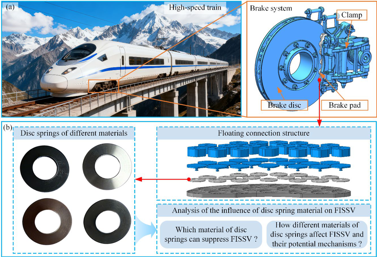
A key component of contemporary transportation, high-speed trains not only promote socioeconomic advancement but also offer a quick and effective means of long-distance travel. The braking system is a crucial component of operational safety and acts as its “lifeline” [1,2]. Figure 1a shows the basic layout of a high-speed train’s braking system. The foundation braking system allows for precise stopping and slowing at speeds below 20 km/h by converting kinetic energy into thermal energy through friction between the brake pads and disc [3,4]. However, this process can easily induce FISSV at the braking interface [5]. This self-excited vibration is caused by periodic fluctuations in friction force between the brake disc and pads. FISSV poses significant hazards: it not only exacerbates braking system instability and degrades braking performance, leading to abnormal wear or even fragmentation of pad friction blocks [6,7], it may also give rise to significant safety hazards, including brake failure, thereby compromising passenger safety. Additionally, the noise produced at the braking interface undermines passenger ride comfort and contributes to environmental pollution along railway corridors [8,9,10,11]. Under the current paradigm emphasizing green and comfortable travel, this issue has garnered widespread attention. Therefore, improving the tribological behavior of the braking interface and suppressing FISSV are of great significance for ensuring train operational safety and enhancing passenger ride experience.
FISSV represents a typical form of periodic self-excited vibration observed in braking systems [12], occurring under the fundamental condition where kinetic friction is lower than static friction. Its essential feature resides in the alternating stick–slip behavior: the driving force is produced by the system’s cyclic buildup and release of elastic energy as well as the difference between the static and kinetic friction coefficients. The contact contacts maintain coordinated velocities and are largely immobile during the stick phase; in the slip phase, sudden relative motion occurs at the interface, accompanied by an abrupt drop in friction force and rapid release of potential energy that induces accelerated motion. The negative damping effect further exacerbates system instability [13,14]. As energy dissipates and relative velocity approaches zero, the recovery of friction force promotes re-adhesion, completing one vibration cycle and initiating the next. The induced mechanism of FISSV is complex and influenced by multiple interacting factors. Existing studies indicate that friction-induced self-excited vibration is a complex nonlinear phenomenon resulting from energy feedback and system instability during relative motion at the contact interface. Its generation mechanism is affected by a combination of factors, including material properties [2], structural parameters [15], process conditions [16], environmental conditions [17], and system boundary support stiffness [18].
In response to FISSV, researchers worldwide have proposed various mitigation strategies targeting its triggers. In terms of material design optimization, Zhang et al. [19] introduced Al2O3 fibers into copper-based brake pads, effectively enhancing their friction performance and stability under different operating conditions while reducing wear and temperature rise, and elucidated the intrinsic relationship between this effect and tribofilm formation. TiN particles were treated by Tian et al. [20] using an electroless copper plating technique, which significantly improved the interfacial bonding state between the particles and the copper matrix. As a result, the composite’s overall mechanical qualities were improved while its porosity, wear loss, and friction coefficient were decreased. Menapace et al. [21] conducted friction testing and created copper-free friction materials made mostly of barite. According to experimental results, barite promotes the formation of a stable friction layer on the material’s surface, which enhances the stability of the friction coefficient and surface temperature. Lertwassana et al. [22] fabricated friction materials using aramid/carbon fiber-reinforced polystyrene composites. Friction and wear tests revealed that this composite possesses excellent mechanical properties, dynamic mechanical properties, and tribological performance. These research findings provide feasible approaches for suppressing friction-induced vibration at the source through material design. Furthermore, energy dissipation mechanisms within structures represent another important avenue for vibration suppression.
Regarding contact interface regulation, in order to improve the tribological performance of graphite, Xu et al. [23] used laser processing technologies to create three different convex-concave textures on graphite surfaces: linear grooves, circular dimples, and isosceles triangular dimples. Li et al. [24] created different brake pad groove patterns and found that the brake disc’s horizontal groove configurations produced a more evenly distributed temperature and stress fields. Zhang et al. [25] designed smooth surfaces, grooved surfaces, and two composite textures with varying flocking densities to conduct an in-depth investigation into the friction mechanism at the sliding interface. The grooved texture produced buffering and lubricating effects by altering the surface topography, which successfully decreased variations in friction behavior, decreased the friction coefficient, and improved wear and friction characteristics. Xu et al. [26] fabricated five types of micro-textures—groove arrays, square pillar arrays, circular pit arrays, regular hexagonal pillar arrays, and trapezoidal pillar arrays—on 304 stainless steel substrates. Through friction and wear tests, they analyzed the influence of these different micro-textures on the friction and wear performance of the 304 stainless steel surface. The aforementioned studies confirm that appropriate surface texturing design can significantly suppress high-frequency friction-induced vibration and noise.
Currently, floating connection structures have attracted significant attention due to their ability to adjust deformation during braking, enhancing the brake interface’s tribological behavior and potentially reducing vibration and noise [27,28,29]. Deng et al. [30], by investigating the influence of fixed versus floating friction block connection structures, discovered that the floating connection structure can successfully lessen noise and vibration brought on by friction. Zhong et al. [31], after comparing floating and fixed structures of brake pads, pointed out that the elastic floating structure can adjust the normal displacement of the friction blocks, promoting closer contact between the blocks and the disc. As a result, the temperature distribution becomes more consistent and the friction coefficient remains constant during the braking operation. Our recent studies [32] have shown that the system’s vibration frequency distribution, vibration modes, and vibration and noise intensity can be significantly changed by changes in disc spring stiffness. However, the choice of material for the disc spring is just as important as stiffness. In addition to undermining the previously mentioned advantages, an improper material selection may also result in new difficulties including increased nonlinear vibration and excessive wear. As a result, choosing the right disc spring material is a useful and efficient way to improve the braking interface’s tribological behavior. It can optimize the interfacial contact state and friction transfer characteristics, thus presenting a potential solution for suppressing FISSV. To clarify how these materials affect tribological performance and aid in FISSV suppression, more research is necessary.
Based on this, this paper establishes the floating brake pad structure of high-speed trains as the core research framework, focusing on a dedicated investigation into the effects resulting from differences in disc spring materials. Figure 1b clearly presents the complete hierarchy of the research object, ranging from the overall train braking system to the details of the core floating connection structure. To comprehensively explore the influence of material differences, this study deliberately selected four typical disc spring materials—304 stainless steel, Mubea-specific spring steel, 50CrVA high-alloy spring steel, and 60Si2MnA silicon-manganese spring steel—as research samples. For brevity, these materials are hereafter referred to as 304, Mubea, 50CrVA, and 60SM, respectively. To systematically reveal the influence mechanism of the aforementioned materials on FISSV, this research employs a comprehensive methodology combining experimental testing and numerical simulation. At the experimental level, a specialized test platform was established based on a multifunctional friction and wear tester. FISSV-related tests were conducted on disc springs made of the four different materials. Real-time vibration and noise signals from the friction interface were recorded using a specialized vibration and noise acquisition device, while displacement sensors simultaneously recorded the displacement trajectory of the friction blocks. Post-test, a multi-dimensional characterization approach was employed for systematic analysis of the friction pair. Initial examination of worn surface morphology was conducted using optical microscopy (OM), the elemental content and microstructure of the worn surfaces were then thoroughly characterized using energy dispersive spectroscopy (EDS), white light interferometry (WLI), and scanning electron microscopy (SEM). Based on the actual structural parameters of the experimental apparatus, a finite element model (FEM) was created on the ABAQUS platform at the simulation level. Dynamic-wear coupling simulations of the friction process were carried out using an explicit dynamics program in conjunction with a wear analysis technique. Finally, through the integration of experimental data and numerical simulation results, the fundamental processes controlling how disc spring material differences affect friction-wear behavior and FISSV were identified, thereby offering a scientific foundation for the material optimization design of floating brake pad structures.

2. Introduction to Research Methods

2.1. Brake Tribology Test

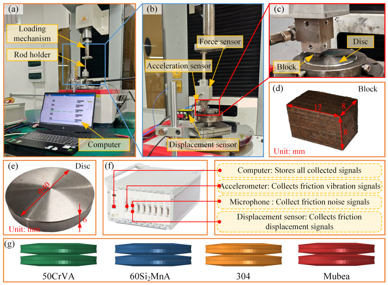
A multipurpose friction and wear test rig was used in this investigation to perform experiments relating to FISSV. The main goal of the study was to look at how disc springs composed of four different materials affected FISSV. The test platform consists of core units such as loading, driving, and data acquisition systems, with the overall structure shown in Figure 2a. To comprehensively capture multi-physical field response signals at the friction interface, a multi-sensor collaborative testing system was established. Microphones (Donghua MTG MK250, Jingjiang City, China), Accelerometer (Donghua 1A341E IEPE, Jingjiang City, China), and displacement sensors (Donghua HG-C1100, Jingjiang City, China) were deployed to synchronously acquire key data including friction noise, loading mechanical characteristics, vibration response, and friction block displacement. The layout positions and corresponding functions of each sensor are illustrated in Figure 2b. Figure 2d,e displays the measurements of the test specimens used in the experiment. The disk has an outside diameter of 40 mm, a thickness of 6 mm, and a friction radius of 13 mm. The wear block was a cube with dimensions of 8 mm in length, 8 mm in width, and 12 mm in height. Its contact wear area was 64 square millimeters. Forged steel is used to make the brake disc, while materials from powder metallurgy are used to make the friction blocks. The composition of brake discs and friction blocks are shown in Table 1 and Table 2. The disc springs, which were made of four different materials, had the same geometric dimensions as shown in Figure 3c: an outer diameter of 8 mm, an inner diameter of 4.2 mm, and a free height of 0.4 mm, to eliminate interference from dimensional differences on the test results.
To ensure consistency in the initial state of the friction interface, all samples underwent a standardized pre-treatment procedure. In order to reduce variations in surface morphology and remove any remaining surface flaws from machining, the contact surfaces of the blocks and the friction disc were first polished using a grinding machine. Subsequently, the polished friction blocks were immersed in an ultrasonic cleaner for degreasing and cleaning to eliminate any adhered contaminants and oil residues. Following the cleaning process, the specimens were dried within a drying apparatus and subsequently stored in a desiccator until required for testing. Prior to formal experimentation, all friction pair specimens were prepared by undergoing a running-in procedure to mitigate poor contact arising from installation deviations and to ensure full face-to-face contact between the blocks and the disc. Once the worn area of the block attained over 85% of its total surface area, the running-in process was deemed complete, and formal testing commenced.
The test parameters for the formal experiments were established as follows: a rotation speed of 2 r/min and an applied load of 200 N. Under these conditions, tests were conducted respectively for the groups corresponding to disc springs made of the four materials. To control for experimental uncertainty, each condition was tested five times, with a single test duration of 60 min. The data acquisition system continuously recorded vibration acceleration, friction noise, displacement, and mechanical signals. Upon completion of the tests, the collected data underwent repeatability verification and statistical analysis. Concurrently, microscopic characterization techniques (such as OM, SEM, EDS, etc.) were employed to observe the friction surface morphology and elemental composition, offering thorough data assistance for examining the ways in which disc springs comprised of various materials affect FISSV. Meanwhile, after the tests, a comprehensive comparison of the morphology and signal data from multiple repeated tests was conducted, abnormal or interfering data were excluded, and the optimal results with typical morphological features and stable signals that truly reflect the interface friction, wear, and vibration laws were selected as representatives for analysis and presentation.

2.2. Method of Finite Element Simulation

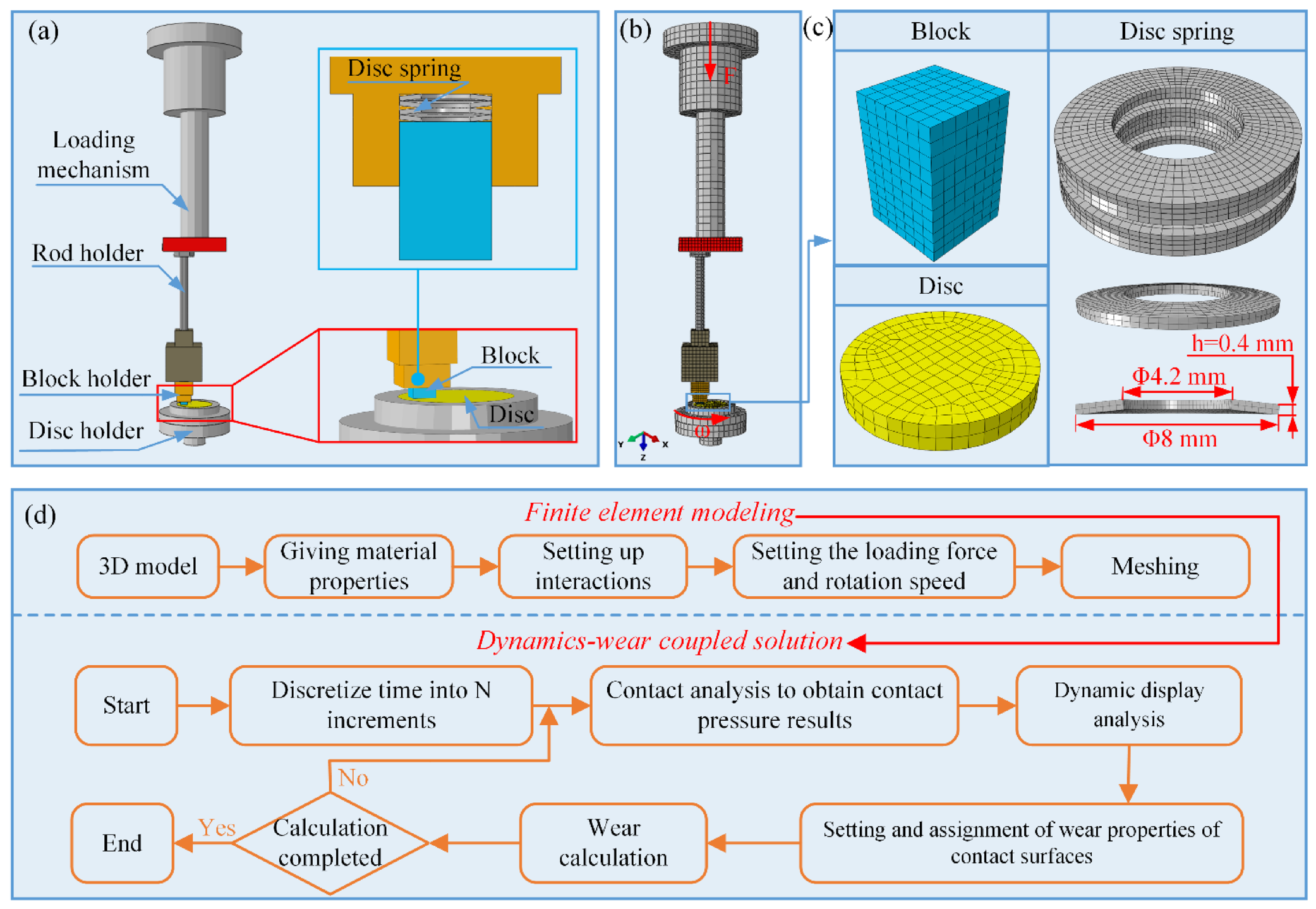
This study is based on the Abaqus2025 finite element software and builds a coupled simulation model of dynamic characteristics and wear behavior for the friction disc friction block coupling system. The model architecture is shown in Figure 3a, and the mesh division of the model is shown in Figure 3b. The physical characteristics and structural parameters of every component strictly matched the observed values, and the FEM was built using the test device’s actual geometric dimensions. Table 3 provides specific parameters. The friction disc’s friction interface was designated as the master surface and the friction block’s contact surface as the slave surface when the surface-to-surface contact algorithm was used. Regarding contact characteristics, frictional contact was set up in the tangential direction, whilst firm contact was given in the normal direction. Based on preliminary test findings, important parameters like the friction coefficient and decay coefficient were calibrated. The static friction coefficient was set at 0.5, the dynamic friction coefficient at 0.3, and the decay coefficient at 1. The boundary constraint conditions were configured as follows: the friction disc and its lower associated components were subjected to a tie constraint that limited all translational and rotational degrees of freedom about the X and Y axes while maintaining only the rotational degree of freedom about the Z axis, with the rotational speed configured at 2 r/min. For the upper assembly comprising the friction block and the rod-type fixture, a tie constraint was similarly implemented, permitting translational motion exclusively in the Z direction. Concurrently, a normal load of 200 N was exerted at the upper end of the fixture. The simulation duration was defined as 2 s, with monitoring concentrated on three parameters: the tangential displacement of the block, the wear depth and the contact pressure at the interface. All model components were meshed using hexahedral elements, with the element type chosen as C3D8R, to improve the precision of numerical computations. By improving convergence and computational correctness for contact analysis, this element type effectively ensures the dependability of the simulation results.
Figure 3d shows the whole process of the finite element simulation procedure. A dynamic-wear coupling simulation analysis approach was used in this study, breaking up the entire solution process into N increments and performing stepwise iterative computations. The operational process for a single increment was described as follows: dynamic display analysis (DDA) was performed once the interface pressure distribution data under stable contact conditions between the block and disc were obtained. The single-step dynamic-wear coupling analysis method was finished when the quantitative evaluation of wear depth was initiated after the contact surface wear property parameters were integrated into the DDA solution module. Through cyclic execution of N incremental steps, all simulation outcomes were ultimately consolidated and acquired. Concurrently, the wear coefficient of the friction block was kept constant at 2 × 10⁻⁶ in this investigation in order to precisely examine the modulation patterns of disc spring material on wear behavior. This parameter, validated through cross-verification of experimental and simulation data, attains an optimal equilibrium between computational efficiency and physical fidelity while ensuring calculation accuracy. This modeling strategy guarantees the validity and dependability of the simulation results in addition to meeting the demands of the single-variable control research paradigm. The wear calculation was performed based on the Archard equation [33], involving a complete formula system including the general form, differential derivation, and incremental step calculation. The specific formulas for wear calculation are detailed in previously published related research results [34].

3. Results and Analysis

3.1. Analysis of Friction and Wear

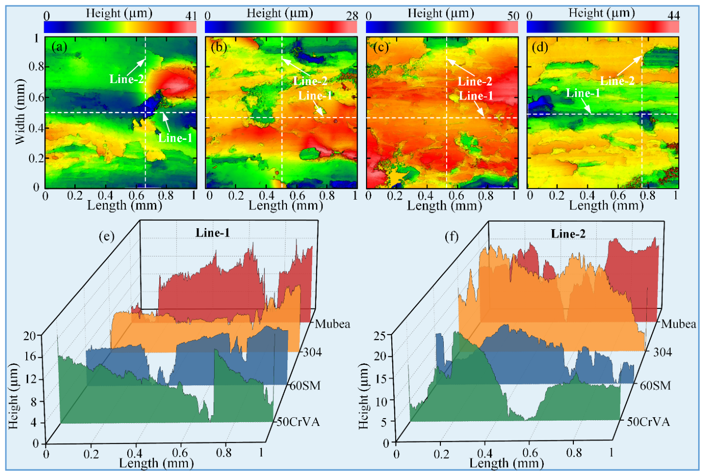
Figure 4 systematically presents the three-dimensional topographic characteristics of the friction block wear surfaces after FISSV simulation tests, along with the two-dimensional profile curve analysis results along corresponding characteristic paths (x-direction, y-direction). Analysis of the three-dimensional topographic features in Figure 4a,d reveals that under each test condition, the friction block surfaces exhibit typical composite wear morphologies, characterized by the coexistence of furrow-like cutting marks and localized material spalling pits, which confirms that abrasive wear and adhesive wear constitute the predominant wear mechanisms. The worn surface of the friction block exhibits obvious anisotropic morphological characteristics along the X and Y directions. Such directional differences directly affect the interface contact pressure distribution, abrasive wear behavior, and energy dissipation law, thereby exerting a significant influence on the friction response and stick-slip vibration characteristics. This is intrinsically consistent with the effect of anisotropic roughness on contact and friction proposed in the literature [35]. Notably, marked variations are observed in the height field distribution on the friction block surfaces across different conditions. The 60SM block demonstrates a comparatively minor surface height differential, suggesting a relatively moderate degree of wear. The three-dimensional topography shows a substantial distribution of uncompacted wear debris accumulations on the surface, and its two-dimensional profile curve shows gentle fluctuations, suggesting smaller spalling pit sizes and lower distribution density on its surface. In contrast, the 304 block displays the largest surface height difference, and the formation of a continuous third-body layer from compacted wear debris can be observed, with the two-dimensional profile curve also confirming the height of its worn surface. The differences in deformation compatibility and stress relaxation properties that disc springs made of different materials display under cyclic braking loads are responsible for this phenomena. Thereby resulting in different levels of uniformity in load transfer from the floating connection configuration to the braking interface. Deep grooves and large spalling pits on the friction block surface are more likely to form at the braking interface when the stiffness of the disc spring material shows poor compatibility with the dynamic response characteristics of the braking system. In contrast, when the disc spring material demonstrates superior elastic recovery capability and load equalization properties, the pressure distribution across the braking interface becomes more uniform, leading to comparatively moderate wear on the friction block surface. In conclusion, a distinct intrinsic correlation exists between the evolution pattern of friction block wear morphology and the mechanical properties of the disc spring material.
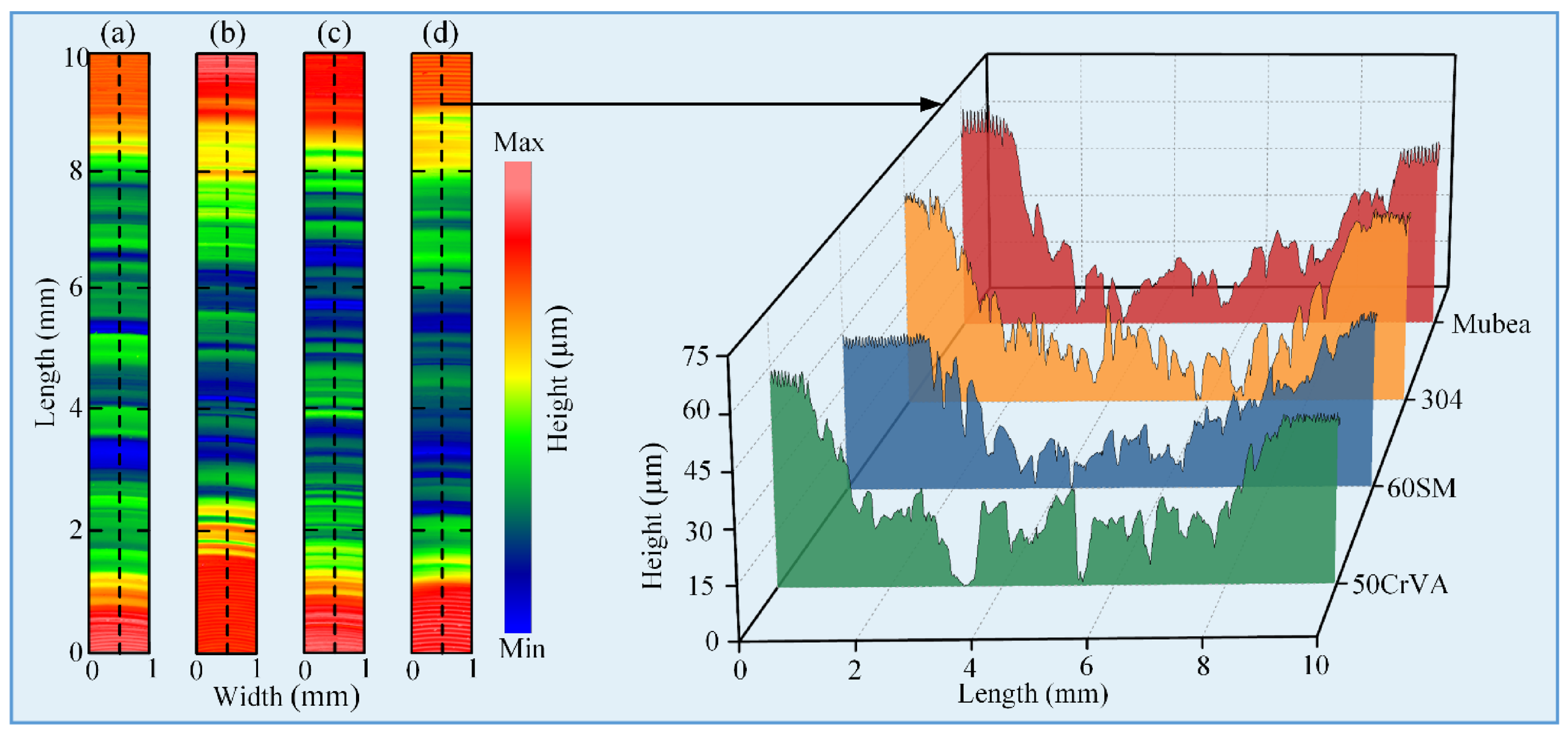
Figure 5 presents the three-dimensional surface topography of the friction disc after testing, along with the corresponding two-dimensional profile curve analysis results. From the three-dimensional topography distribution in Figure 5a,d, it can be observed that under different operating conditions (corresponding to disc springs made of different materials), the friction disc surfaces all exhibit non-uniform height distribution characteristics. The significant fluctuations in color gradients intuitively reflect differences in surface wear, with clear differentiation in the topographic features of the friction discs. The Mubea disc surface shows a wider color gradient span, reflecting more pronounced height fluctuations. This is because the braking stress transferred through the floating connection structure concentrates in specific regions since the stiffness of this disc spring material does not match the dynamic response characteristics of the braking system, thereby promoting the formation of severe wear geometric features on the friction disc surface. In contrast, the color bands on the 60SM disc surface are relatively concentrated, with a more gradual height distribution. This is associated with the excellent load equalization capability of this disc spring material, which alleviates local stress concentration at the braking interface by optimizing the load transfer uniformity of the floating connection, consequently resulting in a milder wear morphology on the friction disc.
Combined with the quantitative analysis from the two-dimensional profile curves on the right, we infer that the contact zones of the friction discs exhibit distinctive furrow wear morphology under all four operation circumstances. This topographic feature mainly displays two basic configurations: an alternating “ridge”-shaped protrusion structure and a “valley”-shaped groove structure. The dynamic plowing action of worn debris particles on the disc surface during the friction process is clearly reflected in this alternating surface topography. The differences in topography are essentially a direct manifestation of how disc springs made of different materials regulate the pressure distribution at the interface through the floating structure. On the 60SM disc surface, due to the excellent load equalization capability of this disc spring material, at the braking interface, the pressure distribution is comparatively uniform, resulting in the formation of uniformly distributed narrow furrows on the disc surface. On the Mubea disc surface, due to the poorer stiffness compatibility of this disc spring material, the degree of pressure concentration at the braking interface is further exacerbated, and the extent of disc surface damage correspondingly intensifies, forming multiple deep furrows.
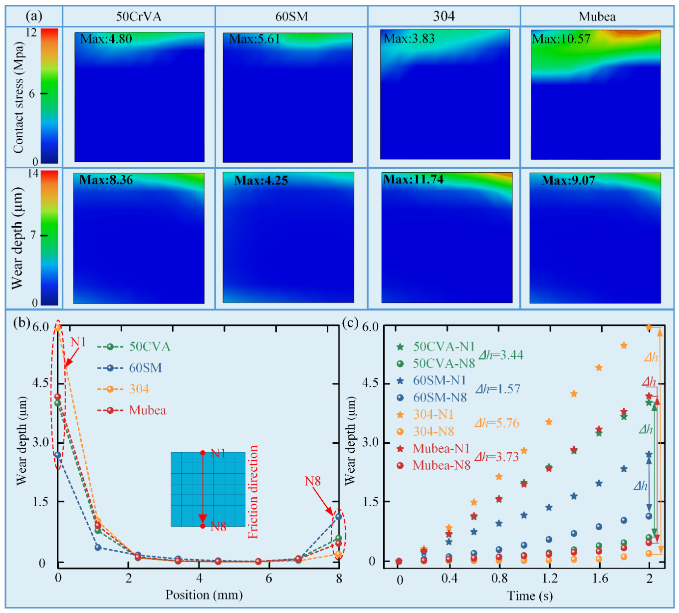
Figure 6 presents the simulation results for friction blocks corresponding to disc springs made of four materials—50CrVA, 60SM, 304, and Mubea—at the conclusion of the finite element analysis, including surface contact pressure distribution, wear depth distribution, and wear evolution characteristics. The friction block surfaces exhibit significant stress localization under all four working circumstances, with the largest contact stress continuously focused in the friction block’s frontal edge region, according to the contact pressure distribution characteristics. Eccentric wear (EW) in the friction blocks is mostly caused by this unequal stress distribution pattern. Fundamentally attributable to fixture deformation and friction block inclination resulting from the adhesive drag effect of the friction disc. The wear depth distribution outcomes further substantiate the presence of EW. The wear depth in the frontal edge region of all friction blocks substantially exceeds that in the rear edge region, with pronounced differentiation in wear characteristics among friction blocks subjected to different operating conditions. Simultaneously, the impact of material properties on wear severity is particularly conspicuous. The maximum wear depth at the frontal edge of the 304 block (11.74 μm) is considerably larger than that of other blocks, indicating its comparatively inferior wear resistance. Conversely, the 60SM block’s maximum wear depth at the frontal edge is only 4.25 μm, suggesting that disc springs composed of this material can more successfully maintain structural strength and elasticity, providing the friction block with improved wear resistance during the friction process. Figure 6b displays the wear depth evolution pattern on the friction block along the friction direction. It is evident that the wear depth at the frontal edge node N1 is substantially higher than that at the rear edge node N8. When paired with the temporal development results of wear depth at nodes N1 and N8 displayed in Figure 6c, the wear depth at the frontal edge N1 exhibits a dynamic rising tendency over time. Moreover, substantial differences exist in the wear depth differential of friction blocks corresponding to disc springs manufactured from various materials. The wear depth differential for the 304 block reaches 5.76 μm, notably greater than the 1.57 μm recorded for the 60SM block.
The wear simulation calculation results are in high agreement with the wear morphology characteristics observed in the experiments. The contact pressure distribution, wear depth differences, and eccentric wear pattern revealed by the simulation can reasonably explain the differences in groove depth and spalling degree on the wear surface of friction blocks under different disc spring materials in the experiments, thereby confirming the reliability of the experimental phenomena from a mechanistic perspective. The experiments and simulations support and complement each other, jointly elucidating the regulatory effect of disc spring material properties on the friction and wear behavior of the braking interface.
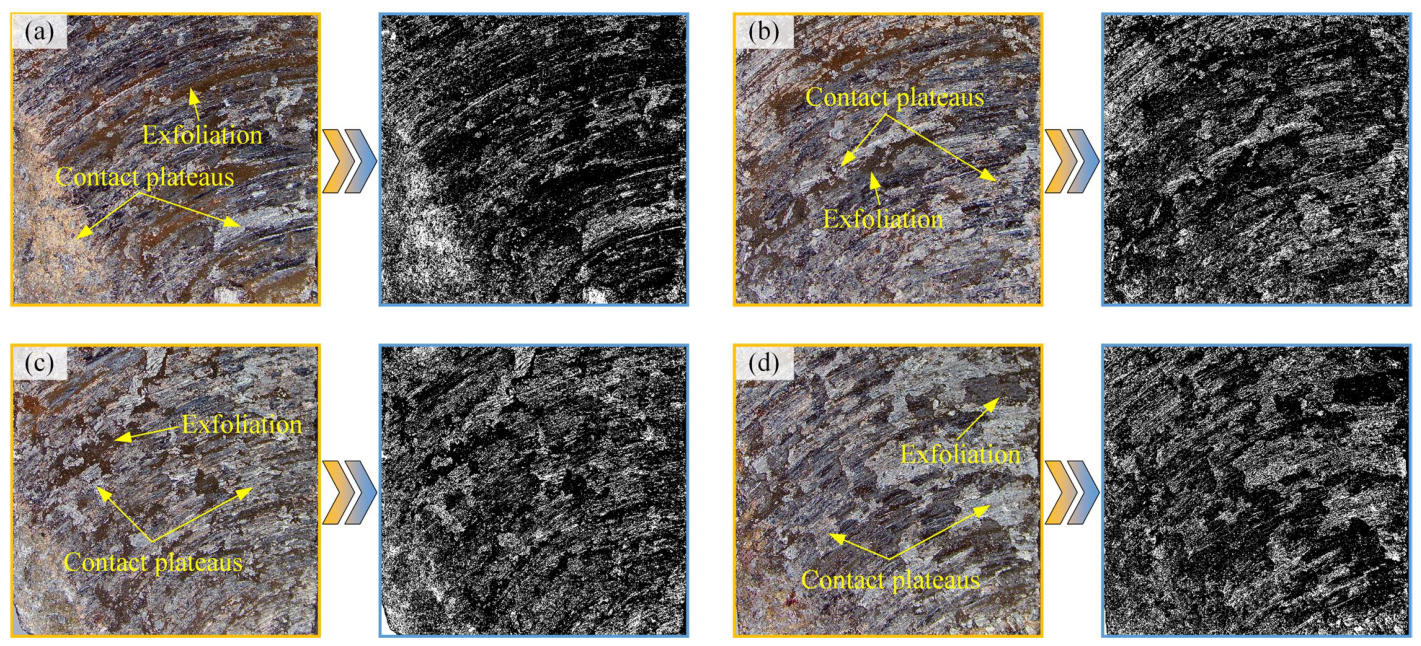
In this work, OM combined with the Otsu threshold segmentation algorithm was employed to analyze the micro-topographical characteristics and contact platform distribution patterns on the worn surfaces of the blocks. The results, presented in Figure 7, reveal the regulatory role of disc spring material on interfacial wear behavior and contact platform evolution. From the overall micro-topographical characteristics, the surfaces of friction blocks corresponding to the four disc spring materials all exhibit typical wear morphologies characterized by the coexistence of contact platforms, spalling pits, and furrows. However, significant differences exist in the contact platform distribution characteristics and the degree of damage among friction blocks corresponding to different disc spring materials. Specifically, the contact platforms and spalling pits on the surface of the 50CrVA block show an orderly alternating distribution. Quantitative analysis indicates a relatively high number of contact platforms, with individual platforms of moderate area and relatively narrow spalling zones around the platform perimeters. Surface of the 60SM block, the contact platform distribution tends to be more dispersed, with slightly smaller individual platform areas and milder spalling pit damage, corresponding to relatively lower intensity of interfacial plowing and adhesive action. On the surface of the 304 block, the proportion of spalling pits is significantly increased, and fine micro-pit structures are visible on the platform surfaces, indicating that the 304 material experiences more severe local shear stress during friction, resulting in more pronounced spalling failure of the material surface layer. The surface of the Mubea block exhibits morphological characteristics with interwoven contact platforms and spalling pits, where the degree of spalling damage around the platform perimeters is intensified, accompanied by a higher degree of compaction at the contact platform junctions.
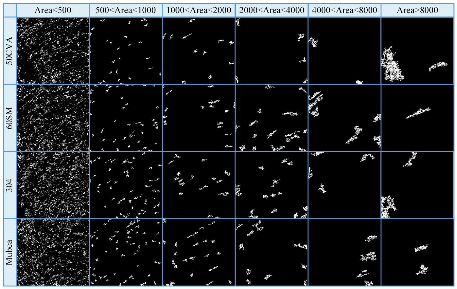
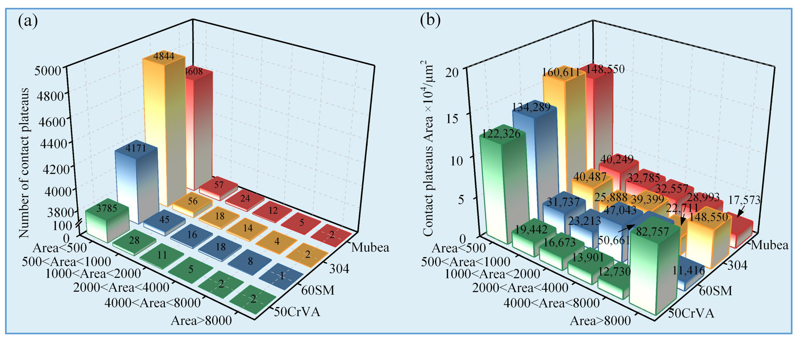
Figure 8 and Figure 9 collectively present the visualized distribution characteristics (Figure 8) and quantitative statistical patterns (Figure 9) of contact platforms on friction blocks corresponding to the four disc spring materials. When taken as a whole, these analyses provide a methodical assessment of the contact platforms’ size distribution, quantity proportion, and area proportion. Significant variations may be seen in the distribution density of contact platforms across different area intervals for blocks corresponding to different disc spring materials, as shown by the displayed graded distribution in Figure 8. The Mubea block and 60SM block exhibit dense distributions of micro-platforms in the interval of areas smaller than 500 μm2, while the 50CrVA block and 304 block primarily display micro and small platforms as their main distribution morphology. The quantitative findings displayed in Figure 9 closely match these visible traits. In reference to the quantity of contact platforms (Figure 9a), the 304 block has up to 4844 platforms in the area interval below 500 μm2, representing the highest number of micro-platforms among all blocks. The 50CrVA block has 3785 platforms in this interval, with an extremely low proportion in the medium-to-large intervals. The 60SM block and 304 block maintain a relatively balanced quantitative distribution of contact platforms in areas below 2000 μm2. Notably, regarding the quantity of large contact surfaces with areas larger than 8000 μm2, the 50CrVA block, 304 block, and Mubea block each have 2, while the 60SM friction block has only 1. An increase in contact platform size drives a fundamental shift in the interfacial contact state from a multi-point dispersed load-bearing mode to a localized concentrated load-bearing mode. This evolution in contact mode not only alters the dynamic vibration characteristics of the braking system but also exacerbates local stress concentration effects. In terms of contact platform area (Figure 9b), the 50CrVA block exhibits the largest total area of contact platforms exceeding 8000 μm2, reaching 82,757 μm2. In contrast, the 60SM block has the smallest total area of large contact platforms, only 11,416 μm2. These characteristic differences are essentially the result of the regulatory influence of disc spring material properties on interfacial tribological behavior, directly affecting the interfacial wear and load-bearing stability of the friction blocks.
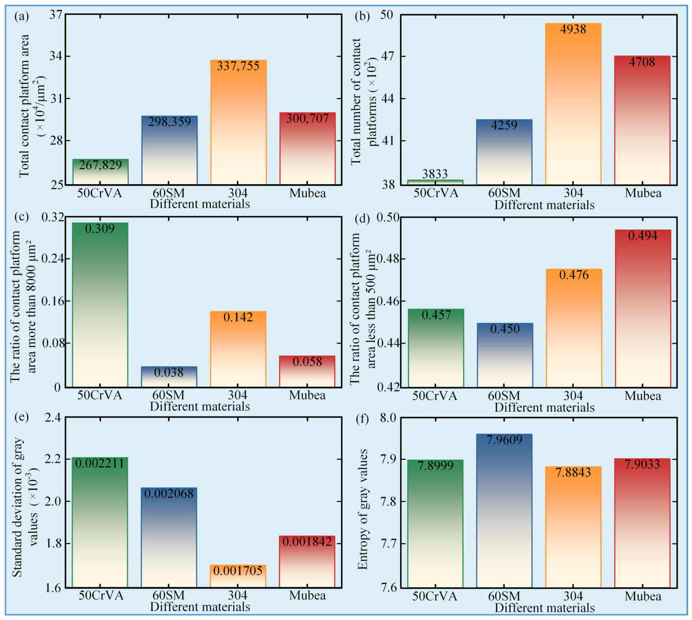
Based on the OM images in Figure 7, a statistical analysis was conducted on the contact platforms on the friction block surfaces. The gross contact platform area, total number, area proportion of large/small contact platforms, and grayscale characteristic parameters of the worn surface were calculated for friction blocks corresponding to different disc spring materials. The results are presented in Figure 10. Regarding the gross contact platform area and the proportion of large platforms, friction blocks corresponding to different disc spring materials exhibit significant differences. The 50CrVA block has the smallest total contact platform area among the four conditions, yet it possesses the highest proportion of large contact platforms (area exceeding 8000 μm2), reaching 0.309. The 304 block has the largest total contact platform area, reaching 337,755 μm2, and its large platform proportion is second only to that of the 50CrVA block. In contrast, the 60SM block has the lowest proportion of large platforms, while its total contact platform area remains at a moderate level. This result indicates that the surface of the 50CrVA block is more prone to forming large-sized contact platforms, whereas the 60SM block effectively suppresses the proportion of large platforms, with contact platforms tending toward a small-to-medium size distribution.
A combined analysis of the total number of contact platforms and the proportion of small platforms reveals that the 304 block exhibits the highest total count of contact platforms, reaching 4938, while keeping a noticeably high percentage of small platforms (less than 500 μm2 in area). The Mubea block exhibits the highest proportion of small platforms, with a total platform count of 4708. The 60SM block has a moderate total number of contact platforms and a relatively low proportion of small platforms. The grayscale characteristic parameters of the worn surface (Figure 10e,f) further corroborate the aforementioned distribution differences. The 50CrVA block surface shows the largest standard deviation of grayscale values, indicating more pronounced height fluctuations on its worn surface and relatively poorer surface flatness. Regarding grayscale entropy, the 60SM block surface exhibits the highest entropy value, suggesting greater randomness in the distribution of its contact platforms, a higher abundance of small-sized platforms, and more pronounced contact platform diversity. The 304 block surface has the lowest entropy value, reflecting relatively weaker uniformity in its contact platform distribution. These characteristic differences are essentially the result of the regulatory influence of disc spring material mechanical properties on wear debris compaction and contact platform evolution processes, directly correlating with the interfacial load-bearing characteristics and wear behavior stability of the blocks.
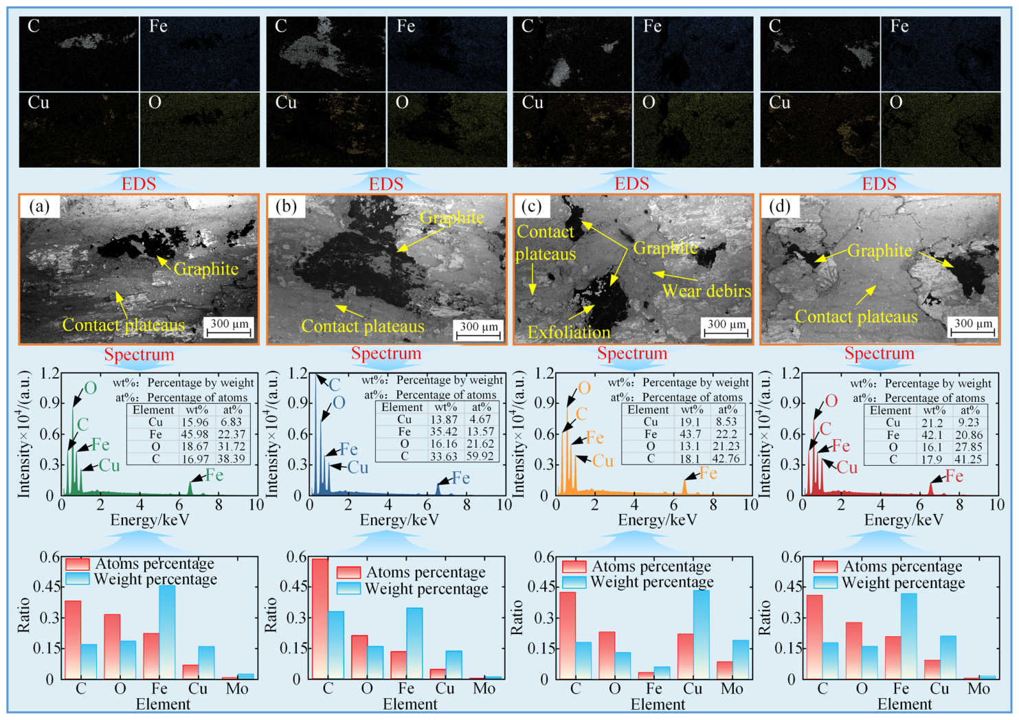
Figure 11 presents the SEM micro-morphology, element distribution characteristics, and EDS element composition analysis results for the corresponding regions on the wear surfaces of friction blocks associated with the four disc spring materials. The SEM micro-morphology images reveal that contact platforms formed by compacted wear debris are present on all friction block surfaces, along with distributed graphite phases. However, notable differences exist in surface damage and structural characteristics among the friction blocks. The surfaces of the 50CrVA block and Mubea block predominantly exhibit an ordered distribution of contact platforms and graphite phases, with sparse scattered wear debris and relatively regular surface morphology overall. The 60SM block surface displays more pronounced aggregation characteristics of the graphite phase, with almost no observable wear debris distribution. In contrast, the surface of the 304 block features not only contact platforms and graphite phases but also evident material spalling and scattered wear debris. EDS spectra further indicate that the primary elements on the surfaces of all four friction blocks are C, O, Fe, Cu, and Mo, albeit with significant variations in element content. The 50CrVA block shows a relatively high atomic percentage of element C, while the proportion of element O remains at a moderate level. The 60SM block exhibits a comparatively larger proportion of element C, with the weight percentage of element O slightly exceeding that of the 304 block. For the 304 block, the atomic percentage of element Cu is notably increased, accompanied by a relative decrease in the proportion of element Fe. The weight percentage of element Fe in the Mubea block is slightly lower than that in the 50CrVA block. These differences in element composition closely correspond to the surface morphological characteristics. The higher proportion of element Cu in the 304 block is associated with the formation of scattered wear debris on its surface, whereas the higher proportion of element C in the 60SM block corresponds to its more aggregated graphite phase distribution. As a lubricating phase, the more concentrated distribution of graphite can reduce interfacial adhesion during the friction process, ultimately contributing to wear mitigation.
It is clear from analyzing the wear and friction characteristics of brake discs and friction blocks under the influence of disc springs made of various materials that differences in disc spring material have a major impact on the uniformity of load transfer and contact pressure distribution at the braking interface, which in turn determines wear morphology and mechanisms. The friction block surfaces all demonstrate composite wear characteristics. Notably, the 304 block exhibits the greatest surface height differential, pronounced wear severity, and the formation of a compacted third-body layer. The 60SM block exhibits the mildest wear, with gentle surface height fluctuations and uncompacted wear debris accumulation. This can be attributed to the fact that when the material stiffness poorly matches the system, localized pressure concentration leads to deep furrows and large-area spalling. Conversely, when the material possesses excellent elastic recovery and load equalization capabilities, wear becomes more moderate. Finite element simulations reveal that contact pressure concentration at the frontal edge of the block gives rise to EW. Among the tested materials, the 304 block exhibits the greatest wear depth at the frontal edge, indicating inferior wear resistance, whereas the 60SM block demonstrates the smallest wear depth, exhibiting the most favorable wear resistance. Analysis of contact platforms reveals that the 60SM block possesses the lowest proportion of large platforms, characterized by a dispersed and highly stochastic contact platform distribution. Micro-morphological and elemental analyses indicate that the surface of the 60SM block displays more pronounced aggregation of the graphite phase, which contributes to mitigating adhesive wear. In contrast, the 304 block surface exhibits a relatively elevated Cu element content, accompanied by material spalling and scattered debris. In summary, the disc spring material exerts a direct influence on wear behavior and friction pair stability by modulating interfacial load distribution, contact platform evolution, and surface compositional characteristics.

3.2. Friction-Induced Vibration and Noise

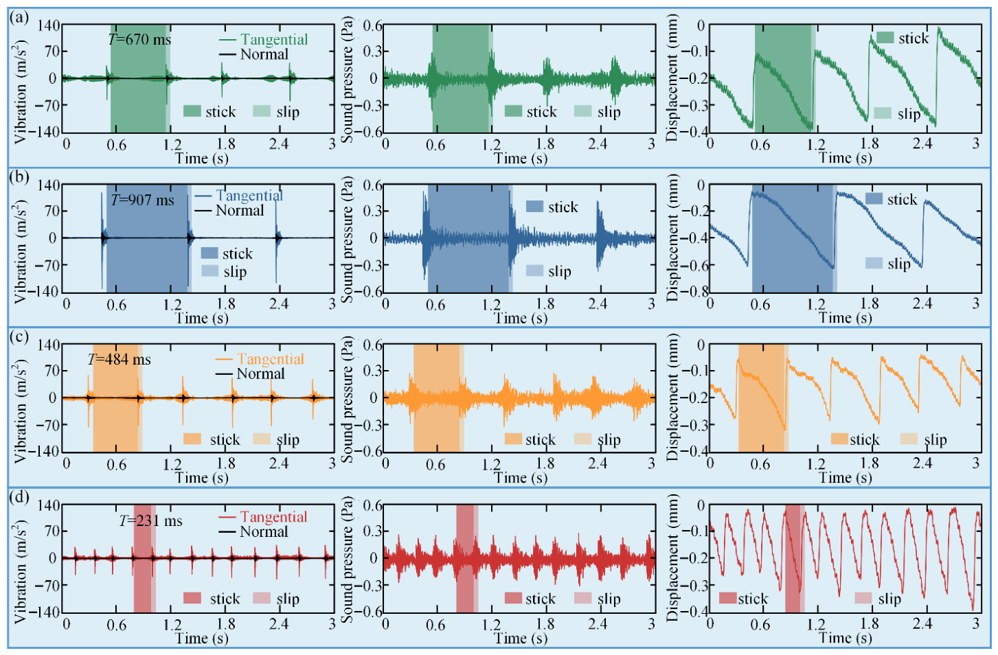
For systems using different disc spring materials, Figure 12 shows the time-domain characteristics of vibration acceleration, noise sound pressure, and block displacement throughout the braking operation. It is clear that all systems demonstrate classic FISSV characteristics, with prominent transient impact features in vibration signals. In the time domain, the concurrently produced noise signals show strong temporal synchronization with the vibration signals. Transient impacts are clearly concentrated during the relative sliding phase between the brake disc and friction block as compared to the block displacement curves, however the vibration intensity is significantly reduced during the relative stick phase. The regulatory effect of disc spring material properties on the system dynamic response is remarkably significant, with clear differentiation in SSV characteristics among different systems. The 50CrVA system exhibits a vibration cycle of 670 ms, with comparatively mild variations in noisy sound pressure and tangential and normal vibration acceleration, a small amplitude of friction block displacement variation, weak signal impacts during stick-slip phase transitions, and an overall more stable dynamic state. The 60SM system shows an extended vibration cycle of 907 ms.
Compared to the 50CrVA system, its transient peaks in noise sound pressure are more pronounced, the fluctuation amplitude of the displacement signal increases, and the signal impact intensity during stick-slip transitions rises noticeably. The 304 system has a shortened vibration cycle of 484 ms, with significantly increased fluctuation frequencies in vibration acceleration and noise sound pressure, more frequent stick-slip alternation in friction block displacement, and denser intermittent signal fluctuations. The Mubea system exhibits the shortest vibration cycle, merely 231 ms, while simultaneously demonstrating the highest fluctuation frequencies in tangential vibration acceleration and noise sound pressure among the four systems, along with the most severe oscillations in friction block displacement, presenting the strongest FISSV phenomenon. The 50CrVA system and 60SM system have longer durations of the stick phase, with longer intervals between transient impacts during the slip phase, whereas the 304 system, and particularly the Mubea system, show substantially shortened stick phase durations and more concentrated transient impacts during the slip phase. The impact of various disc spring materials on the dynamic behavior of the system is the source of these variations.
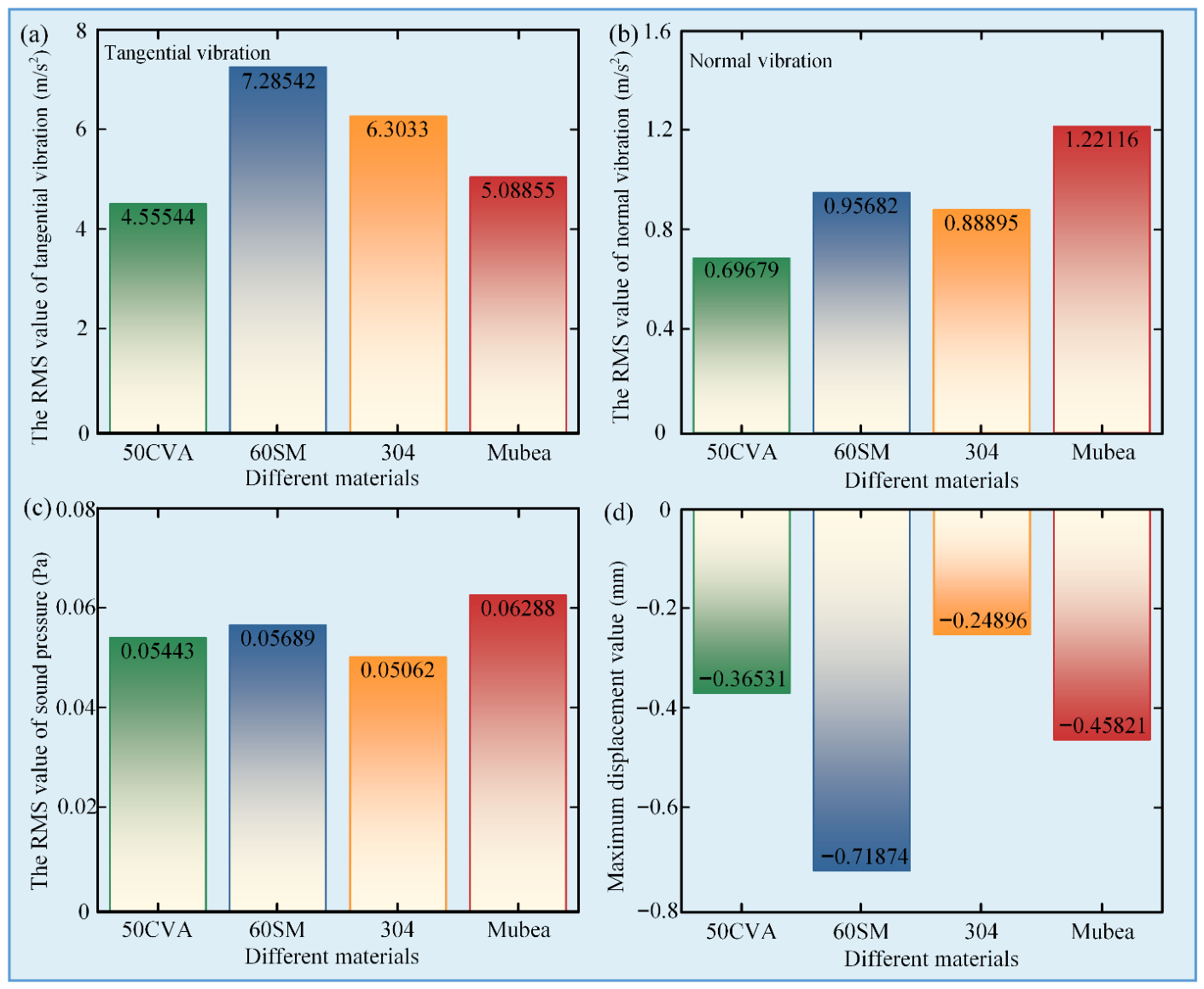
Furthermore, the vibration acceleration root mean square (RMS) values, noise RMS values, and maximum friction block displacement for systems with different disc spring materials were statistically analyzed, as shown in Figure 13. Statistical analysis of the tangential vibration RMS values reveals significant differences in tangential vibration intensity among systems with different disc spring materials. The 60SM system exhibits the largest tangential vibration RMS value, while the 50CrVA system shows the smallest. This result indicates that the use of 50CrVA material for the disc spring achieves superior suppression of tangential vibration in the system. Statistical analysis of normal vibration RMS values shows that the Mubea system has the highest normal vibration RMS value, with the 50CrVA system again exhibiting the smallest. Results for noise RMS values indicate that the Mubea system has the largest noise RMS value, while the 304 system shows the smallest. This trend is not fully synchronized with that of the vibration RMS values, suggesting that noise generation is influenced by multiple interacting factors. Analysis of the maximum block displacement reveals that the 60SM block exhibits the largest maximum displacement amplitude, a trend highly consistent with its tangential vibration RMS value. Both the tangential vibration and displacement amplitude of the 60SM system are the largest, indicating a clear correlation between tangential vibration intensity and friction block displacement amplitude.
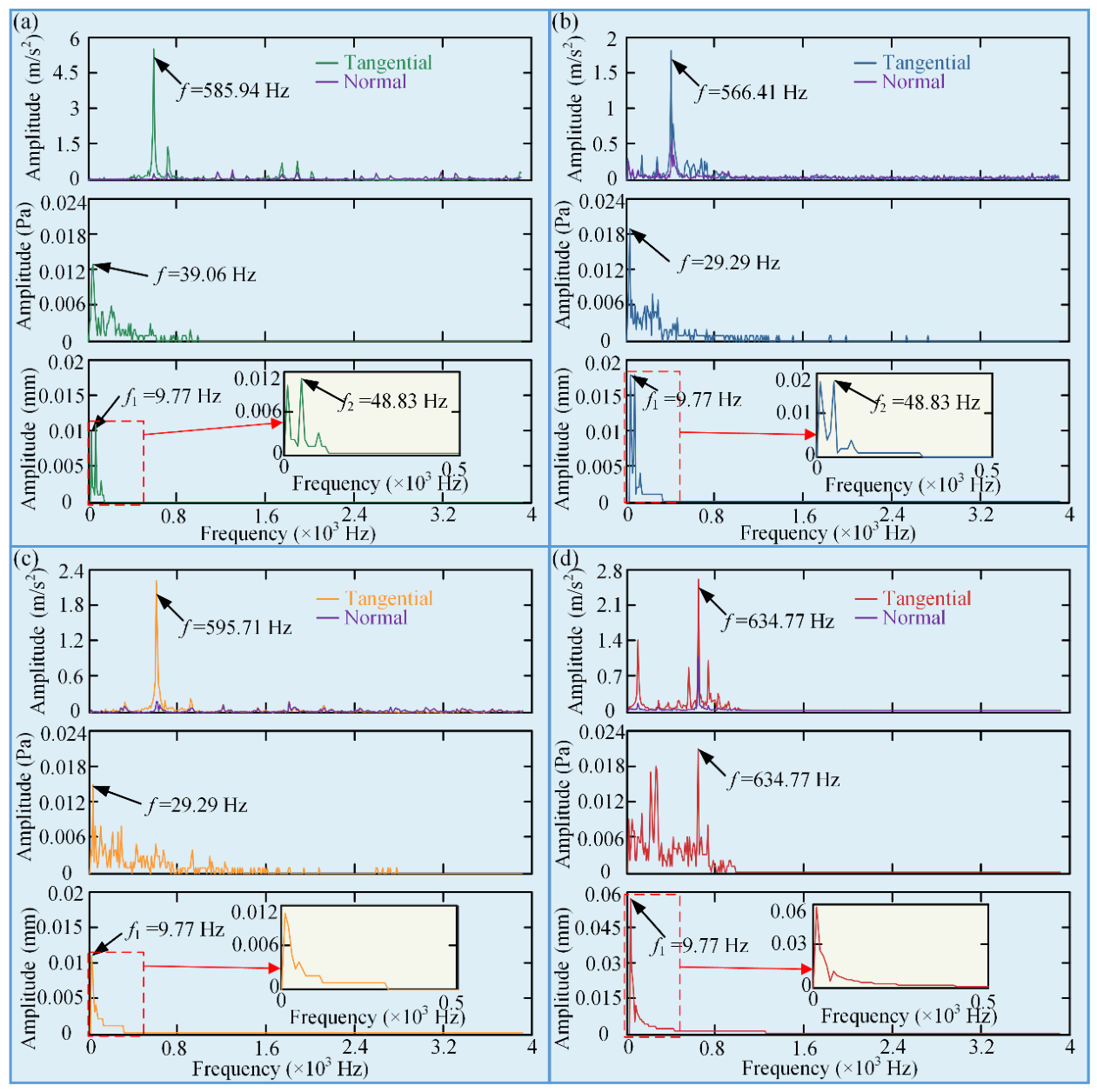
Figure 14 presents the frequency-domain analysis results of SSV acceleration, noise sound pressure, and friction block displacement for the four disc spring material systems during braking. The 50CrVA system exhibits a dominant tangential vibration characteristic frequency of 585.94 Hz, with the largest frequency-domain amplitude among the four systems. Its dominant noise frequency is 39.06 Hz, and the friction block displacement shows dual characteristic frequencies at 9.77 Hz and 48.83 Hz. The dominant vibration frequency of the 60SM system decreases to 566.41 Hz, with a dominant noise frequency of 29.29 Hz. The displacement characteristic frequencies remain consistent with those of the 50CrVA system, though the frequency-domain amplitude of displacement shows an increase. The 304 system has a dominant vibration frequency of 595.71 Hz, a dominant noise frequency consistent with that of the 60SM system, and maintains the same displacement characteristic frequencies. The Mubea system exhibits an increased dominant vibration frequency of 634.77 Hz, with its dominant noise frequency fully coupled to this value. While the displacement characteristic frequencies remain at 9.77 Hz, this system demonstrates the largest frequency-domain amplitudes for both noise and displacement among the four, corresponding to the strongest dynamic response energy and most severe SSV. Overall, the 60SM system effectively suppresses concentrated impacts in the dynamic response. Compared to the large vibration frequency-domain amplitude of the 50CrVA system, the 60SM system not only reduces the dominant vibration frequency but also achieves a more dispersed distribution of vibration energy, effectively mitigating the severity of the vibration response. Although the frequency-domain amplitude of displacement shows a slight increase, the overall fluctuation intensity of dynamic parameters remains significantly lower than that of the Mubea system, demonstrating its effectiveness in suppressing severe SSV during braking and contributing to enhanced dynamic stability of the system.
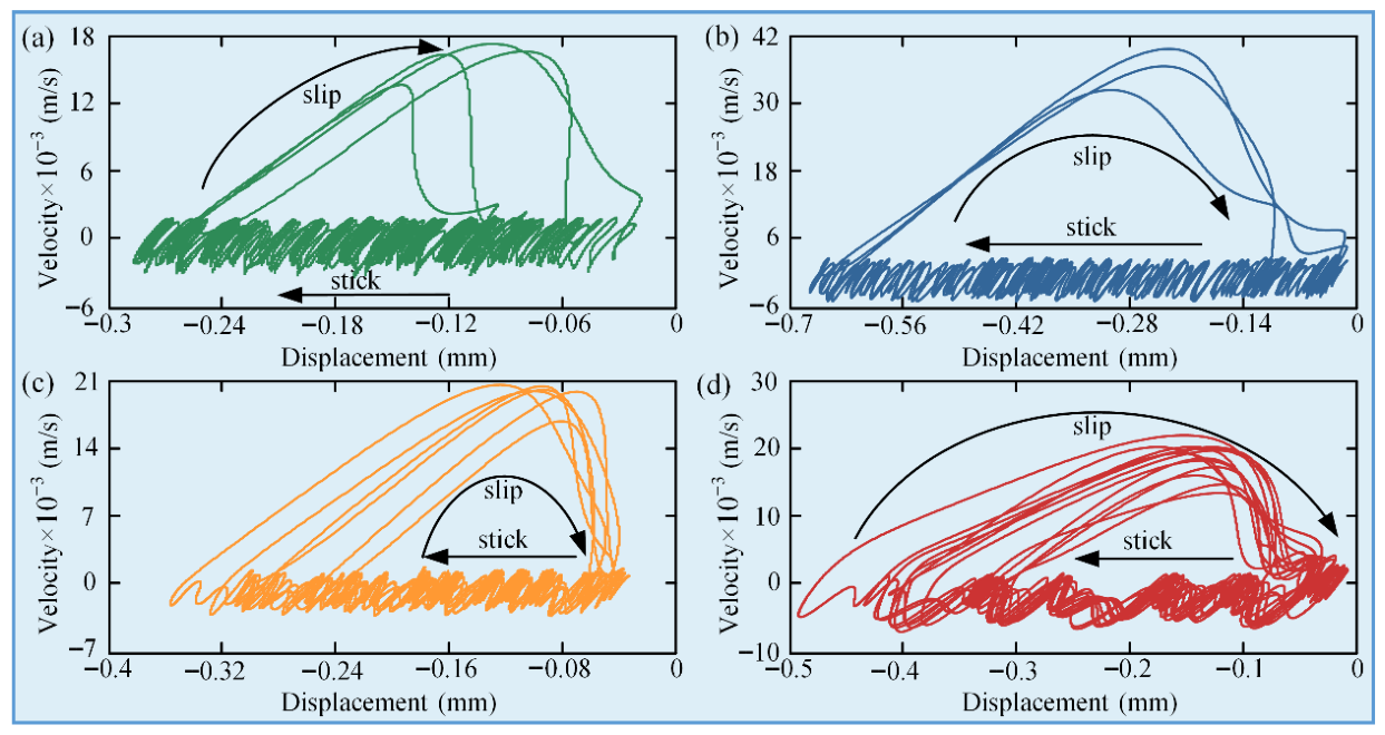
The velocity-displacement phase diagrams of the friction blocks depicted in Figure 15 were created after the displacement signals of the blocks were differentiated to get velocity data. Phase diagram analysis shows that each block’s motion trajectory has unique limit cycle features, demonstrating that FISSV occurred in the systems corresponding to all four types of friction blocks. In the phase diagram of the 50CrVA block, the limit cycle appears relatively compact, enclosing a smaller phase plane region. In the phase diagram of the 60SM block, the limit cycle becomes more regular, with an expanded enclosed phase plane region, while the trajectories during the stick phase maintain good concentration. Notably, the number of limit cycles in its phase diagram is the smallest among the four types of friction blocks, reflecting a relatively low stick-slip alternation frequency in this system. The phase diagram of the Mubea block exhibits the highest number of limit cycles, with significantly increased velocity and displacement amplitudes during the slip phase and increased dispersion of trajectories during the stick phase. This feature not only reflects the strongest FISSV vibration intensity in this system but also suggests a higher frequency of stick-slip alternation and more intense nonlinear dynamic response. This series of phase diagram characteristics forms a complete correspondence with the previously observed differences in vibration cycles and amplitudes in the time-domain analysis, as well as the patterns of vibration frequencies and energy distribution in the frequency-domain analysis, further demonstrating that the fundamental elements controlling the FISSV behavior and nonlinear dynamic response of the braking system are the properties of the disc spring material in the floating structure.
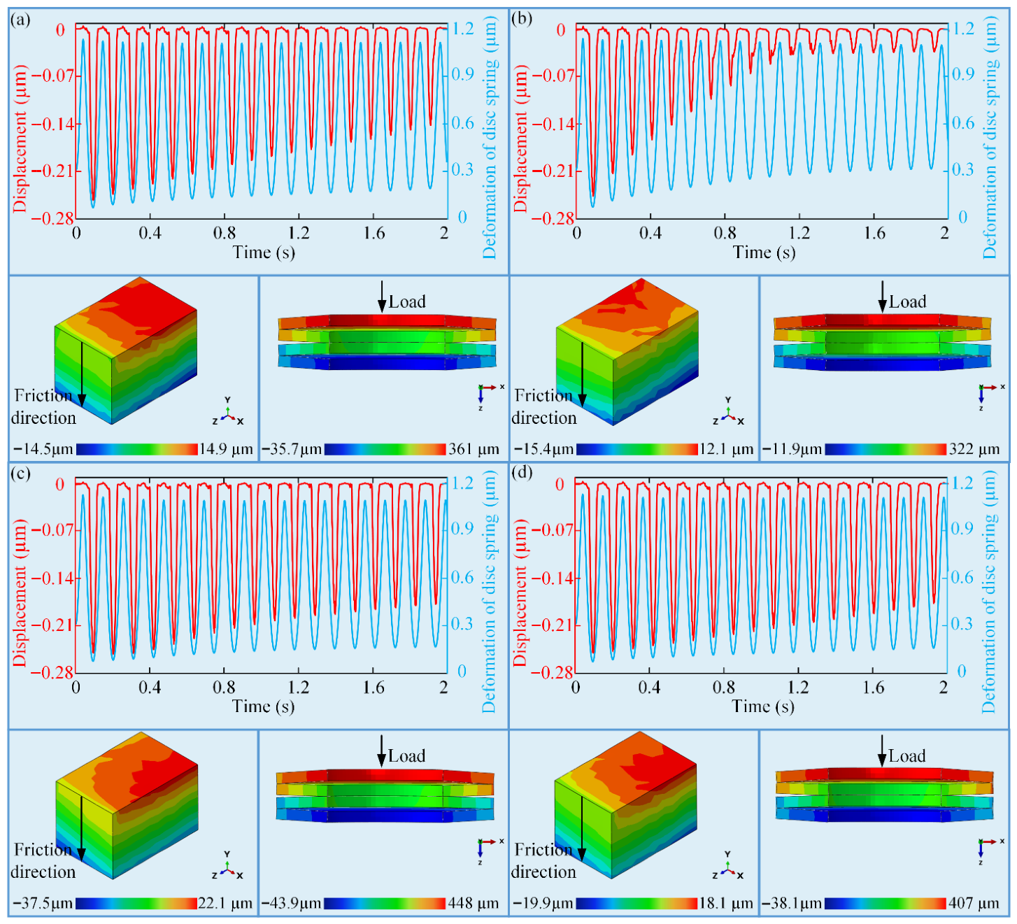
Figure 16 presents the time-domain curves of block normal displacement and disc spring deformation corresponding to the four disc spring materials, along with the normal deformation contour plots of the disc spring assembly and friction block at the peak deformation points. From the time-domain curves, it can be observed that the deformation of disc springs corresponding to all four materials is substantially greater than the normal displacement of the friction blocks, with varying degrees of phase lag between the two waveforms. The 50CrVA system exhibits relatively good synchronization between friction block displacement and spring deformation. The 60SM system shows the most pronounced phase lag, with friction block displacement waveforms appearing more rounded. The Mubea system demonstrates relatively larger fluctuation amplitudes in friction block displacement among the four types. The results of the normal deformation cloud map of the friction block further reveal the tilting state of the block during the friction process. For the 50CrVA block, the leading edge side is predominantly subjected to tension, while the trailing edge side exhibits compression, with a relatively small degree of block tilting. The tilting characteristics of the 60SM block are similar to those of the 50CrVA block, but the stress distribution in the spring deformation contour plot is more uniform, reflecting smoother interfacial force transfer. The tilting degree of the Mubea block shows some increase, while the 304 block exhibits the most significant tilting among the four materials, which corresponds to its larger displacement fluctuation characteristics observed in the time-domain curves.
Disc springs made of various materials have a significant impact on the system’s dynamic response and SSV characteristics, according to an analysis of the impact of disc spring material within the floating structure on FISSV at the braking interface. Vibration acceleration, noise sound pressure, and friction block displacement show synchronized transient impacts during the slip phase, while vibration intensity is significantly attenuated during the stick phase. Experimental results show that typical FISSV phenomena occur under all material conditions. The disc spring material exerts a critical regulatory influence on vibration cycle, amplitude, and frequency distribution. Notably, the 60SM system displays the longest vibration cycle and the most stable dynamic response. The Mubea system shows the shortest cycle, with the most severe fluctuations in vibration acceleration and noise, demonstrating the strongest FISSV phenomenon. Velocity-displacement phase diagram analysis demonstrates that all systems exhibit limit cycle behavior, thereby providing confirmation of FISSV occurrence. Finite element simulation and deformation analysis indicate that disc springs made of different materials possess varying degrees of deformation compatibility and phase lag, directly influencing the tilting state of the friction block and normal displacement fluctuations. The 50CrVA and 60SM systems show better deformation synchronization and more uniform interfacial load transfer, while the 304 and Mubea systems exhibit pronounced friction block tilting and exacerbated displacement fluctuations, consistent with the trend of enhanced vibration response. In summary, the disc spring material, by regulating system stiffness, deformation characteristics, and interfacial load transfer behavior, emerges as a key controlling factor affecting the vibration cycle, intensity, frequency distribution, and nonlinear dynamic characteristics of FISSV.


4. Discussion

This work demonstrates that the disc spring material, a crucial elastic element in the floating brake pad structure, has a significant impact on the wear and friction behavior of the braking interface based on the findings of the experiments and finite element analysis, FISSV features as well as the system’s nonlinear dynamic response via its physical and mechanical characteristics. The mechanical properties of the disc spring material, especially its stiffness and elasticity, play a crucial role in controlling the contact pressure distribution at the braking interface, which in turn controls the wear morphology and underlying mechanisms from the standpoint of interfacial friction and wear. When the disc spring material possesses excellent elasticity and load equalization capability, the pressure distribution at the braking interface is uniform, with the block surface predominantly featuring multi-point dispersed small-to-medium sized contact platforms and fine furrows, resulting in mild and uniform wear (Figure 4b and Figure 7b). Conversely, when the material demonstrates poor stiffness compatibility or insufficient elasticity, localized contact pressure concentration is prone to develop, thereby favoring the formation of large contact platforms, wear debris is consolidated into a continuous third-body layer on the friction block surface, which has deep grooves and macroscopic spalling pits (Figure 4c and Figure 5c). As the disc spring material transitions from 60SM to 304 or Mubea, the contact platform distribution evolves from uniformly dispersed to locally concentrated, with a significant increase in the proportion of large-sized platforms (Figure 8 and Figure 9). These large platforms bear most of the normal pressure, leading to sharp increases in local frictional heat and shear stress, which exacerbates furrow propagation and material spalling (Figure 10 and Figure 11). Therefore, the disc spring material fundamentally governs the wear mechanisms and evolution processes by regulating the interfacial contact state.
In terms of FISSV characteristics, the material properties (stiffness, damping) of the disc springs are correlated with the vibration intensity, period, and nonlinear behavior of the system. All materials produce typical SSV, according to time-domain analysis (Figure 12), with brief effects in acceleration, noise, and displacement appearing during the slip phase. However, material differences lead to distinct dynamic responses. It is inferred that the stiffness of the disc spring directly affects the equivalent stiffness of the system, thereby changing the natural frequency and the rate of energy accumulation and release. It is inferred that the stiffness of the disc spring directly affects the equivalent stiffness of the system, thereby changing the natural frequency and the rate of energy accumulation and release. Its damping characteristics are believed to dominate the dissipation efficiency of vibration energy. Phase portrait analysis (Figure 15) further confirms that the Mubea system corresponds to the largest number and widest range of limit cycles, indicating the strongest nonlinear vibration and highest energy level. The limit cycles of the 60SM system are regular and few in number, suggesting a more controlled stick-slip process.
Finite element simulation results indicate that disc springs made of different materials exhibit varying deformation compatibility under identical loads, leading to differentiated tilting angles of the friction blocks (Figure 6). Materials with excellent elasticity and favorable stress relaxation characteristics enable the friction block to maintain a small and stable tilt, thereby achieving more uniform contact pressure distribution at the interface (Figure 6a) and mitigating stress concentration at the leading edge as well as the EW phenomenon. Conversely, materials with poor deformation compatibility exacerbate friction block tilting, causing severe concentration of contact pressure at the leading edge. This not only significantly increases wear depth in this region (Figure 6c) but also accelerates the accumulation and intensifies the release of interfacial friction force during the stick phase, thereby exacerbating FISSV. The simulation results also validate the regulatory role of disc spring material on the system’s dynamic response (Figure 16); In particular, the material directly affects the SSV cycle and intensity by altering the system’s dynamic properties and interfacial friction state.
In conclusion, this work methodically illustrates how disc spring material affects the SSV behavior of floating brake structures from a variety of angles, such as the growth of wear morphology, the distribution of contact platforms, vibration and noise response, and nonlinear dynamics of the system. Through their inherent stiffness, elasticity, and damping characteristics, disc spring materials regulate the uniformity of load distribution at the braking interface, the stability of the contact state, and the processes of vibration energy accumulation and dissipation within the system. The results demonstrate that 60Si2MnA spring steel exhibits the best comprehensive performance in balancing wear control and vibration suppression, providing a key basis for the material selection of elastic elements in train floating brake pads.

5. Conclusions

With the goal of achieving FISSV suppression through optimized design of the floating friction block structure, this study investigated the impact of disc spring material variations on interfacial tribological behavior and vibration characteristics in order to address the problem of FISSV caused by intense friction between the brake disc and brake pads of high-speed trains. The following is a summary of the main conclusions:
(1)
The stiffness and elasticity of the disc spring constitute critical factors governing load transfer at the braking interface. 60Si2MnA spring steel, owing to its superior elastic recovery and load equalization capability, encouraged the interface’s most consistent contact pressure distribution, yielding a stable friction block surface morphology predominantly characterized by dispersed, randomly distributed small-to-medium sized contact platforms, accompanied by the mildest wear. In contrast, materials such as 304 stainless steel, due to poor compatibility, readily induced localized stress concentration, causing the friction block surface to develop deep grooves, broad contact platforms, and macroscopic spalling pits, which significantly worsens abrasive and adhesive wear. The finite element simulation results further validate the above wear laws. There are significant differences in the contact pressure and wear depth of friction blocks corresponding to different materials. For 60Si2MnA, the interfacial contact pressure distribution is more uniform and the wear depth is smaller, whereas for 304, obvious stress concentration and severe eccentric wear occur. The simulation results are highly consistent with the experimental laws and provide quantitative support for the wear mechanisms.
(2)
Among material properties, stiffness and damping determine the equivalent dynamic parameters of the system, thereby producing differentiated FISSV responses. The Mubea material, characterized by high stiffness and low damping, resulted in the shortest system vibration cycle, the most concentrated impacts, the strongest nonlinearity, and the most severe SSV. The 60Si2MnA system, exhibiting the best comprehensive performance, achieved dispersion of vibration energy in the frequency domain while maintaining the longest cycle, effectively suppressing severe impacts and demonstrating the optimal vibration suppression potential. The simulation further reveals the differences in normal displacement, deformation coordination, and tilt angle of friction blocks under different disc spring materials. The 60Si2MnA system exhibits a small friction block tilt, smooth displacement fluctuations, and good phase synchronization, while the Mubea and 304 systems show obvious friction block tilt and severe displacement fluctuations. The dynamic characteristics obtained from the simulation are in high agreement with the experimental observations, providing a direct mechanical basis for the differences in vibration response.
(3)
Differences in the deformation compatibility of disc spring materials constitute the intrinsic mechanism significantly influencing FISSV characteristics. The 60Si2MnA material enabled better synchronization between disc spring deformation and friction block displacement, resulting in minimal friction block tilting, thereby achieving the most uniform contact pressure and wear depth distribution and fundamentally alleviating stress concentration. Conversely, the mechanical impetus for intense FISSV was provided by the 304 material, which caused significant friction block tilting and phase lag, severe contact pressure concentration, and EW at the leading edge.
(4)
This study provides explicit material selection criteria for disc springs applied in floating brake structures, where 60Si2MnA spring steel is validated as the preferred candidate owing to its well-balanced performance in interfacial load distribution, wear resistance, and friction-induced stick-slip vibration suppression. For engineering braking system design, it is crucial to select disc spring materials with moderate stiffness, favorable elastic recovery, and high structural stability, so as to achieve a favorable match between contact interface state and system dynamic behavior. Excessively high stiffness or insufficient elastic matching tends to destroy interface contact uniformity and trigger intensified wear and unstable vibration, which means that material stiffness matching should be carefully considered according to actual service conditions.

Author Contributions

J.P.: Writing—original draft, Software, Investigation, Funding acquisition, Formal analysis, Data curation. Z.X.: Writing—original draft, Methodology, Funding acquisition, Formal analysis, Data curation. S.D.: Writing—original draft, Software, Methodology, Investigation, Formal analysis. J.Z.: Writing—original draft, Software, Investigation, Data curation. X.L.: Writing—review & editing, Validation, Methodology. All authors have read and agreed to the published version of the manuscript.

Funding

This research was supported the National Natural Science Foundation of China under Grant No. 52305187, Guangxi Natural Science Foundation under Grant No. 2024GXNSFAA010180 and No. 2023GXNSFBA026326, and Yunnan Provincial Key Laboratory of Advanced Equipment Intelligent Manufacturing Technology Program under No. KLYAEIMTY2024003.

Data Availability Statement

Dataset available on request from the authors.

Conflicts of Interest

The authors declare that they have no known competing financial interests or personal relationships that could have appeared to influence the work reported in this paper.

References

  1. Xu, Y.X.; Zhou, H.B.; Chen, Q.; Liu, D.L.; Han, Y.; Deng, M.W.; Yao, P.P. Progress of copper-based friction materials for high-speed train: Tribological property involving components, interfaces, and tribo-layers. Rev. Mater. Res. 2025, 1, 100014. [Google Scholar] [CrossRef]
  2. Zhang, J.K.; Xiang, Z.Y.; Zhang, Q.X.; Feng, S.X.; Yu, Z.; Wang, X.C.; Mo, J.L.; He, D.Q. A method to improve the tribological performance of Cu-based powder metallurgy friction materials for the high-speed trains braking system: Enhancement of the performance of the friction block disc spring. Wear 2025, 566–567, 205751. [CrossRef]
  3. Zhang, Q.X.; Liu, H.; He, Z.C.; Mo, J.L.; Jin, W.W.; Shen, M.X.; Zhao, C.G. Impact of initial braking temperature on thermal-induced brake fade during long-downhill operations. Eng. Fail. Anal. 2025, 167, 109077. [Google Scholar] [CrossRef]
  4. Wang, Q.; Wang, Z.W.; Mo, J.L.; Gebreyohanes, M.Y.; Wang, R.C.; Allen, P. A novel dynamics model of a trailer bogie brake system and its application in stability analysis. Mech. Syst. Signal Process. 2022, 172, 108966. [Google Scholar] [CrossRef]
  5. Ibrahim, R.A. Friction-Induced Vibration, Chatter, Squeal, and Chaos—Part II: Dynamics and Modeling. Appl. Mech. Rev. 1994, 47, 227–253. [Google Scholar] [CrossRef]
  6. Wang, A.Y.; Mo, J.L.; Wang, X.C.; Zhu, M.H.; Zhou, Z.R. Effect of surface roughness on friction-induced noise: Exploring the generation of squeal at sliding friction interface. Wear 2018, 402–403, 80–90. [Google Scholar] [CrossRef]
  7. Lu, C.; Yin, J.B.; Mo, J.L.; Wang, J.Y. Accumulated wear degradation prediction of railway friction block considering the evolution of contact status. Wear 2022, 494–495, 204251. [Google Scholar] [CrossRef]
  8. Prezelj, J.; Murovec, J.; Huemer-Kals, S.; Häsler, K.; Fischer, P. Identification of different manifestations of nonlinear stick–slip phenomena during creep groan braking noise by using the unsupervised learning algorithms k-means and self-organizing map. Mech. Syst. Signal Process. 2022, 166, 108349. [Google Scholar] [CrossRef]
  9. Zhao, X.W.; Gräbner, N.; von Wagner, U. Avoiding creep groan: Investigation on active suppression of stick-slip limit cycle vibrations in an automotive disk brake via piezoceramic actuators. J. Sound Vib. 2019, 441, 174. [Google Scholar] [CrossRef]
  10. Neis, P.D.; Ferreira, N.F.; Poletto, J.C.; Matozo, L.T.; Masotti, D. Quantification of brake creep groan in vehicle tests and its relation with stick–slip obtained in laboratory tests. J. Sound Vib. 2016, 369, 63–76. [Google Scholar] [CrossRef]
  11. Balaram, B.; Santhosh, B.; Awrejcewicz, J. Frequency entrainment and suppression of stick–slip vibrations in a 3 DoF discontinuous disc brake model. J. Sound Vib. 2022, 538, 117224. [Google Scholar] [CrossRef]
  12. Wang, X.C.; Huang, B.; Wang, R.L.; Mo, J.L.; Ouyang, H. Friction-induced stick-slip vibration and its experimental validation. Mech. Syst. Signal Process. 2020, 142, 106705. [Google Scholar] [CrossRef]
  13. Hoffmann, N.; Fischer, M.; Allgaier, R.; Gaul, L. A minimal model for studying properties of the mode-coupling type instability in friction induced oscillations. Mech. Res. Commun. 2002, 29, 197–205. [Google Scholar] [CrossRef]
  14. Hoffmann, N.; Gaul, L. Effects of damping on mode-coupling instability in friction induced oscillations. ZAMM-J. Appl. Math. Mech./Z. Angew. Math. Mech. 2003, 83, 524–534. [Google Scholar] [CrossRef]
  15. Xiang, Z.Y.; Zhang, J.K.; Xie, S.L.; Xiao, Z.M.; Tang, B.; He, D.Q. A method to enhance the performance of elastic damping component to improve tribological behavior at the high-speed train braking interface: Deformation optimization through perforation structure. Wear 2025, 560–561, 205599. [Google Scholar] [CrossRef]
  16. Tong, X.; Wang, S.M. Analysis of Wear Vibration Behavior of Micro-Textured Coated Cemented Carbide Considering High-Order Scale. Coatings 2024, 14, 791. [Google Scholar] [CrossRef]
  17. Vladescu, S.C.; Lumby, R.; Gant, A.; Dyer, H.; Reddyhoff, T. Using lubricant composition to control friction-induced-vibration in an elastomer-steel contact representing a hydraulic seal. Tribol. Int. 2025, 202, 110346. [Google Scholar] [CrossRef]
  18. Zhang, Q.X.; Yu, Z.; Liu, H.; Mo, J.L.; Xiang, Z.; Zhu, S.; Jin, W.W. Analysis of friction-induced vibration and wear characteristics during high-speed train friction braking process. Tribol. Int. 2024, 196, 109701. [Google Scholar] [CrossRef]
  19. Zhang, P.; Zhang, L.; Fu, K.X.; Wu, P.F.; Cao, J.W.; Shijia, C.R.; Qu, X.H. The effect of Al2O3 fiber additive on braking performance of copper-based brake pads utilized in high-speed railway train. Tribol. Int. 2019, 135, 444–456. [Google Scholar] [CrossRef]
  20. Tian, Y.N.; Wei, L.; Wang, X.M.; Li, Z.; Dou, Z.H.; Zhang, T.A. Microstructure and Properties of Copper-Coated Titanium Nitride Particle-Reinforced Copper Matrix Graphite Composites. Russ. J. NON-Ferr. Met. 2024, 65, 103–112. [Google Scholar] [CrossRef]
  21. Menapace, C.; Leonardi, M.; Matějka, V.; Gialanella, S.; Straffelini, G. Dry sliding behavior and friction layer formation in copper-free barite containing friction materials. Wear 2018, 398–399, 191–200. [Google Scholar] [CrossRef]
  22. Lertwassana, W.; Parnklang, T.; Mora, P.; Jubsilp, C.; Rimdusit, S. High performance aramid pulp/carbon fiber-reinforced polybenzoxazine composites as friction materials. Compos. Part B Eng. 2019, 177, 107280. [Google Scholar] [CrossRef]
  23. Xu, K.S.; Yuan, Z.Y.; Luo, Y.; Xie, Y.K.; Xu, Q.Y.; Gao, X.; Xu, J.M. Frictional performance of surface-textured phenolic resin-impregnated graphite materials under water lubrication. Mater. Res. Express 2023, 10, 125601. [Google Scholar] [CrossRef]
  24. Li, J.; Li, J. Thermodynamic Properties of the Textured Brake System Considering Multi-factor. J. Phys. Conf. Ser. 2023, 2501, 012011. [Google Scholar] [CrossRef]
  25. Zhang, H.H.; Ni, J.; Yang, L.Q.; Feng, K.; Meng, Z.; Zhu, Z.F. Synergistic lubrication and fracture mechanisms of composite surface textures. Tribol. Int. 2024, 198, 109866. [Google Scholar] [CrossRef]
  26. Xu, R.; Wang, Y.P.; Liu, H.X.; Qi, W.T.; Wang, Z.K.; Su, J.X. Study on Friction and Wear Behaviors of Micro Texture Shape and Its Modified Surface. J. Phys. Conf. Ser. 2020, 1681, 012015. [Google Scholar] [CrossRef]
  27. Jearsiripongkul, T.; Chakraborty, G.; Hagedorn, P. Stability analysis of a new model for floating caliper disk brake. In Proceedings of the 2002 IEEE International Conference on Industrial Technology, 2002 IEEE ICIT ’02, Bankok, Thailand, 11–14 December 2002; IEEE: Piscataway, NJ, USA, 2002; pp. 535–539. [Google Scholar]
  28. Kim, K.; Yoo, N.; Lee, E. Vibrational Instability Analysis for Railway Brake System Equipped with Flexible Pad Structure. Int. J. Automot. Technol. 2022, 23, 1117–1125. [Google Scholar] [CrossRef]
  29. Yin, J.B.; Wu, Y.K.; Lu, C.; Chen, W.; Mo, J.L.; Zhou, Z.R. The Influence of Friction Blocks Connection Configuration on High-Speed Railway Brake Systems Performance. Tribol. Lett. 2021, 69, 122. [Google Scholar] [CrossRef]
  30. Deng, S.H.; Xie, G.X.; Wang, H.; Xiang, Z.Y.; Tang, B.; Wang, X.C.; He, D.Q. High-temperature tribological behavior of high-speed train braking interfaces: A comparison of fixed and floating friction block joint structures. Wear 2025, 580–581, 206283. [Google Scholar] [CrossRef]
  31. Zhong, W.G.; Zhang, X.H.; Wang, Z.J.; Zhang, X.L.; Yan, Q.Z. The braking performance of pads for high-speed train with rigid and flexible structure on a full-scale flywheel brake dynamometer. Tribol. Int. 2023, 179, 108143. [Google Scholar] [CrossRef]
  32. Deng, S.H.; Ma, S.Y.; Xie, G.X.; Xiang, Z.Y.; Zhang, Q.X.; He, D.Q.; Mo, J.L. Improving thermal-wear-vibration performance of high-speed train braking interfaces via floating structure stiffness design. Appl. Therm. Eng. 2025, 279, 127826. [Google Scholar] [CrossRef]
  33. Archard, J.F. Contact and Rubbing of Flat Surfaces. J. Appl. Phys. 1953, 24, 981–988. [Google Scholar] [CrossRef]
  34. Deng, S.H.; Xiang, Z.Y.; Zhang, Q.X.; Wang, H.P.; Feng, S.X.; Yu, Z.; Mo, J.L. Effect of friction block thickness on the high-temperature tribological behavior of the braking interface of high-speed train. Tribol. Int. 2025, 201, 110232. [Google Scholar] [CrossRef]
  35. Afferrante, L.; Putignano, C.; Menga, N.; Carbone, G. Friction in rough contacts of linear viscoelastic surfaces with anisotropic statistical properties. Eur. Phys. J. E 2019, 42, 80. [Google Scholar] [CrossRef] [PubMed]
Figure 1. Brake pad floating connection configuration and high-speed rail foundation braking system. (a) Trains and the key parts of their braking systems; (b) Examining the floating connection structure and the impact of disc springs made of different materials on FISSV.
Lubricants 14 00194 g001
Figure 2. FISSV simulation experiments. (a) A multipurpose friction and wear testing device and its essential parts; (b) The main sensors used in the tests and where they are mounted; (c) A close-up of the friction pair inside the testing apparatus; (d) The friction block test specimen’s dimensions; (e) The friction disc test specimen’s dimensions; (f) FISSV signal data acquisition system; (g) Schematic representation of the disc spring structure and stacking arrangement.
Lubricants 14 00194 g002
Figure 3. Explicit dynamics-wear coupling simulation process. (a) Three-dimensional representation of the testing apparatus, key structural elements, and mounting position of the disc spring; (b) FEM of the testing apparatus; (c) FEM of the friction disc, friction block, and disc spring; (d) Finite element analysis simulation workflow.
Lubricants 14 00194 g003
Figure 4. Three-dimensional topography results of friction block wear surfaces after testing. (a) 50CrVA block; (b) 60SM block; (c) 304 block; (d) Mubea block; (e) Profile curves in the x-direction; (f) Profile curves in the y-direction.
Lubricants 14 00194 g004
Figure 5. Three-dimensional topography results of the friction disc surface after testing. (a) 50CrVA disc; (b) 60SM disc; (c) 304 disc; (d) Mubea disc.
Lubricants 14 00194 g005
Figure 6. Contact pressure distribution and wear depth distribution of the block at the completion of the finite element simulation. (a) Contact pressure and wear depth on the block surface; (b) The wear evolution process on the block surface; (c) The wear depth at the frontal edge node N1 and rear edge node N8 on the block surface as a function of time.
Lubricants 14 00194 g006
Figure 7. Contact plateaus’ spatial distribution on the friction block’s worn surface after testing. (a) 50CrVA block; (b) 60SM block; (c) 304 block; (d) Mubea block.
Lubricants 14 00194 g007
Figure 8. Results of statistical analysis of the block surface segmentation of the contact platform.
Lubricants 14 00194 g008
Figure 9. Contact platforms on the worn block surface are statistically described. (a) Contact platforms’ quantitative distribution; (b) Contact platforms’ areal distribution.
Lubricants 14 00194 g009
Figure 10. Contact platforms on the worn block surface are statistically described. (a) Total contact platform coverage area; (b) Total number of contact platforms; (c) Percentage of contact platforms with an area greater than 8000 μm2; (d) The percentage of contact platforms that are less than 500 μm2; (e) Grayscale intensity standard deviation on the worn block surface; (f) Grayscale distribution entropy on the worn block surface.
Lubricants 14 00194 g010
Figure 11. Micro-morphology, element distribution, and element composition of the block wear surface obtained by SEM after testing. (a) 50CrVA block; (b) 60SM block; (c) 304 block; (d) Mubea block.
Lubricants 14 00194 g011
Figure 12. Evolution of SSV, noise, and displacement during tribological tests. (a) 50CrVA system; (b) 60SM system; (c) 304 system; (d) Mubea system.
Lubricants 14 00194 g012
Figure 13. SSV characteristics during the testing process. (a) Tangential vibration RMS value; (b) Normal vibration RMS value; (c) Noise RMS value; (d) Maximum friction block displacement.
Lubricants 14 00194 g013
Figure 14. Frequency-domain analysis of SSV, noise, and displacement during testing. (a) 50CrVA system; (b) 60SM system; (c) 304 system; (d) Mubea system.
Lubricants 14 00194 g014
Figure 15. Velocity-displacement phase diagram analysis of friction blocks. (a) 50CrVA block; (b) 60SM block; (c) 304 block; (d) Mubea block.
Lubricants 14 00194 g015
Figure 16. The disc spring assembly’s deformation contour plots at peak deformation and the friction block’s normal deformation contour plots are presented alongside the normal displacement and disc spring deformation curves. (a) 50CrVA; (b) 60SM; (c) 304; (d) Mubea.
Lubricants 14 00194 g016
Table 1. Chemical compositions of brake disc.
ElementNiCrMnMoCSiFe
Content (wt%)1.81.10.750.50.310.25Balance
Table 2. Chemical compositions of friction block.
ElementCuGraphiteFeMoS2SiCFeCrOthers
Content (wt%)45–5018–2013–154–62–46–83–5
Table 3. Key components of the multifunctional friction and wear test and their material properties.
Parts NameMaterialDensity (kg/m3)Young’s Modulus (GPa)Poisson’s Ratio
Brake discForged steel78002100.3
Friction blockCopper-based PM58006.50.3
Disc spring 151CrVA steel78002000.3
Disc spring 260Si2MnA78502100.3
Disc spring 3304 steel79501850.3
Disc spring 4Mubea steel78502050.3
Others45# steel78002100.3
Disclaimer/Publisher’s Note: The statements, opinions and data contained in all publications are solely those of the individual author(s) and contributor(s) and not of MDPI and/or the editor(s). MDPI and/or the editor(s) disclaim responsibility for any injury to people or property resulting from any ideas, methods, instructions or products referred to in the content.