Article

Numerical and Experimental Investigation of Fretting Wear in Connecting Rod Big-End Bearings of Nuclear Emergency Diesel Generators


1
Equipment Reliability Technology Center, Suzhou Nuclear Power Research Institute,Shenzhen 518000, China
2
China Nuclear Power Operation Co., Ltd., Shenzhen 518031, China
3
School of Mechanical Engineering, Shanghai Jiao Tong University, Shanghai 200240, China
*
Author to whom correspondence should be addressed.
Lubricants 2026, 14(4), 151; https://doi.org/10.3390/lubricants14040151
Submission received: 12 February 2026 / Revised: 11 March 2026 / Accepted: 13 March 2026 / Published: 31 March 2026

Abstract

The operational reliability of Emergency Diesel Generators (EDGs) is paramount for the safety of nuclear power plants. This study investigates the fretting wear mechanism on the non-working back-face of connecting rod big-end bearings—a critical failure mode that can lead to catastrophic engine damage. A synergistic approach was employed, integrating theoretical pressure calculations, on-site strain measurement experiments, and high-fidelity non-linear finite element analysis (FEA). The results demonstrate that while the theoretical design back-face pressure ranges from 8.1 to 10.1 MPa, the actual pressure is highly sensitive to bolt preload. A 16.2% attenuation in preload (from 550 kN to 461 kN), common during maintenance cycles, causes the interfacial pressure to drop to 6.9 MPa, falling below the recommended safety threshold of 7 MPa required to inhibit fretting. Furthermore, comparative experiments reveal that used bearings exhibit significantly lower and less uniform radial pressure retention compared to new bearings, even when physical dimensions appear compliant. Dynamic FEA indicates that peak inertial loads induce an out-of-roundness (DOR) of 0.295 mm, triggering a transition from a “partial slip” to a “macro-slip” regime at the interface. The findings confirm that the coupling of preload attenuation and loss of bearing elasticity drives the fretting process, providing a theoretical basis for optimized maintenance and selective assembly strategies.

1. Introduction

Nuclear power plant safety relies on multiple redundant systems, where Emergency Diesel Generators (EDGs) serve as the sole reliable independent power source during Loss of Off-site Power (LOOP) or accident conditions; their functional integrity is a critical barrier for ensuring reactor shutdown, maintaining core cooling, and preventing severe accidents [1,2]. Regulatory bodies (e.g., US NRC, IAEA) impose stringent requirements on EDG startup success rates and continuous operational reliability, as any failure mode could directly threaten the safety margin of the plant.
As the operating life of nuclear units increases, the degradation of EDGs—which remain in standby for long periods—has become increasingly prominent. Statistical data indicates that failures of main engine components (e.g., pistons, connecting rods, bearings) are primary causes of EDG downtime [3,4,5]. Specifically, failures of connecting rod bearings, which are among the most heavily loaded moving parts, are often sudden and catastrophic, potentially leading to the scrapping of the engine block.
Traditional failure analyses of connecting rod bearings often focus on lubrication-related failures, particularly seizure and scuffing under inadequate lubrication conditions [6,7,8,9,10]. Fatigue-related damage mechanisms, such as surface fatigue and spalling caused by repeated contact stresses, have also been widely reported in the literature [11,12,13,14,15]. However, wear on the non-working side (back-face) of the bearing, which can evolve into bearing loosening or “spun bearings,” has received less attention. In high-power-density diesel engines, the big-end bore undergoes significant elastic deformation—characterized as a “flattening-stretching” cycle [16,17,18]. This macro-deformation induces fretting wear, defined by small-amplitude relative slips (typically in the micron range) between the bearing back-face and the bore [19,20,21,22].
From a tribological perspective, fretting wear is governed by the interaction between normal contact pressure, tangential micro-displacement, and the frictional properties of the interface. According to classical fretting theory, the contact interface may evolve through three regimes: full stick, partial slip, and gross slip. When the normal clamping pressure is sufficiently high, the interface remains in a stable stick state and relative motion is suppressed. However, if the contact pressure decreases or if cyclic structural deformation induces tangential displacement exceeding the frictional resistance, localized micro-slip may occur, leading to fretting damage characterized by oxide debris formation, surface polishing, and progressive material removal.
The intensity of fretting is governed by several structural and assembly parameters, including big-end bore stiffness, bolt preload, and bearing interference (crush height). Previous studies have investigated the effects of structural deformation and assembly conditions on bearing performance [23,24,25]. In addition, lubrication behavior and mixed-lubrication dynamics in journal bearings have been extensively studied [26,27,28]. However, studies addressing the coupling of these factors (back-face pressure, preload, stiffness) in the context of nuclear power plant (NPP) EDGs remain scarce.
From a tribological perspective, fretting wear at the bearing back-face originates from the coupling between insufficient normal contact pressure and cyclic tangential displacement induced by structural deformation. When the contact pressure decreases or when the dynamic deformation of the big-end bore generates tangential micro-displacements exceeding the frictional resistance at the interface, the contact state may transition from a stable stick regime to partial slip or gross slip, ultimately leading to fretting damage. Therefore, understanding the relationship between assembly preload, structural deformation, and interfacial contact pressure is essential for clarifying the tribological mechanism of back-face wear in EDG connecting rod bearings.
This paper addresses this gap by combining theoretical design analysis, on-site strain measurement, and dynamic finite element analysis (FEA) to investigate the evolution of back-face pressure and structural deformation, thereby revealing the tribological mechanism responsible for abnormal fretting wear and providing engineering solutions for safety-class equipment.

2. Materials and Methods

2.1. Structural Description

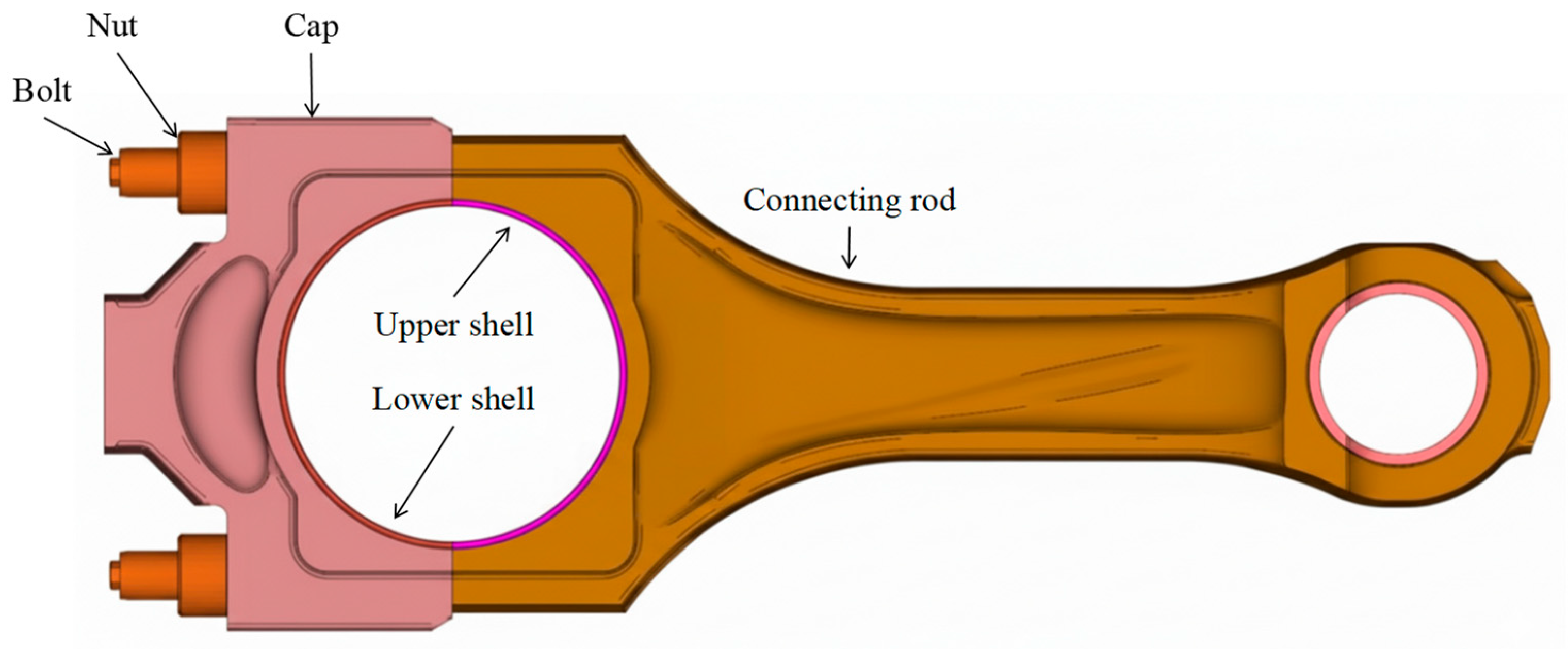
The studied EDG features an 18-cylinder V-type configuration. As shown in Figure 1, the connecting rod assembly primarily consists of the rod body, the big-end cap, the bearing shells (upper and lower shells), and the connecting rod bolts. This bearing is cast with copper–lead alloy on a carbon steel substrate and is the most commonly used thin-walled bearing bush in diesel engines.

2.2. Theoretical Calculation of Bearing Back-Face Pressure

When the bearing shells are installed in the bore, a specific “crush height” is required to ensure sufficient radial pressure upon assembly, thereby keeping the shell in tight contact with the bore. In this study, the big-end bore and the bearing shells are simplified as a “concentric cylinder” model to calculate the radial compressive stress and the circumferential stress [29]. Key parameters involved in the calculation include the big-end bore diameter tolerance, preload of bolts, and the crush height, as shown in Table 1.

2.3. Experimental Strain Measurement

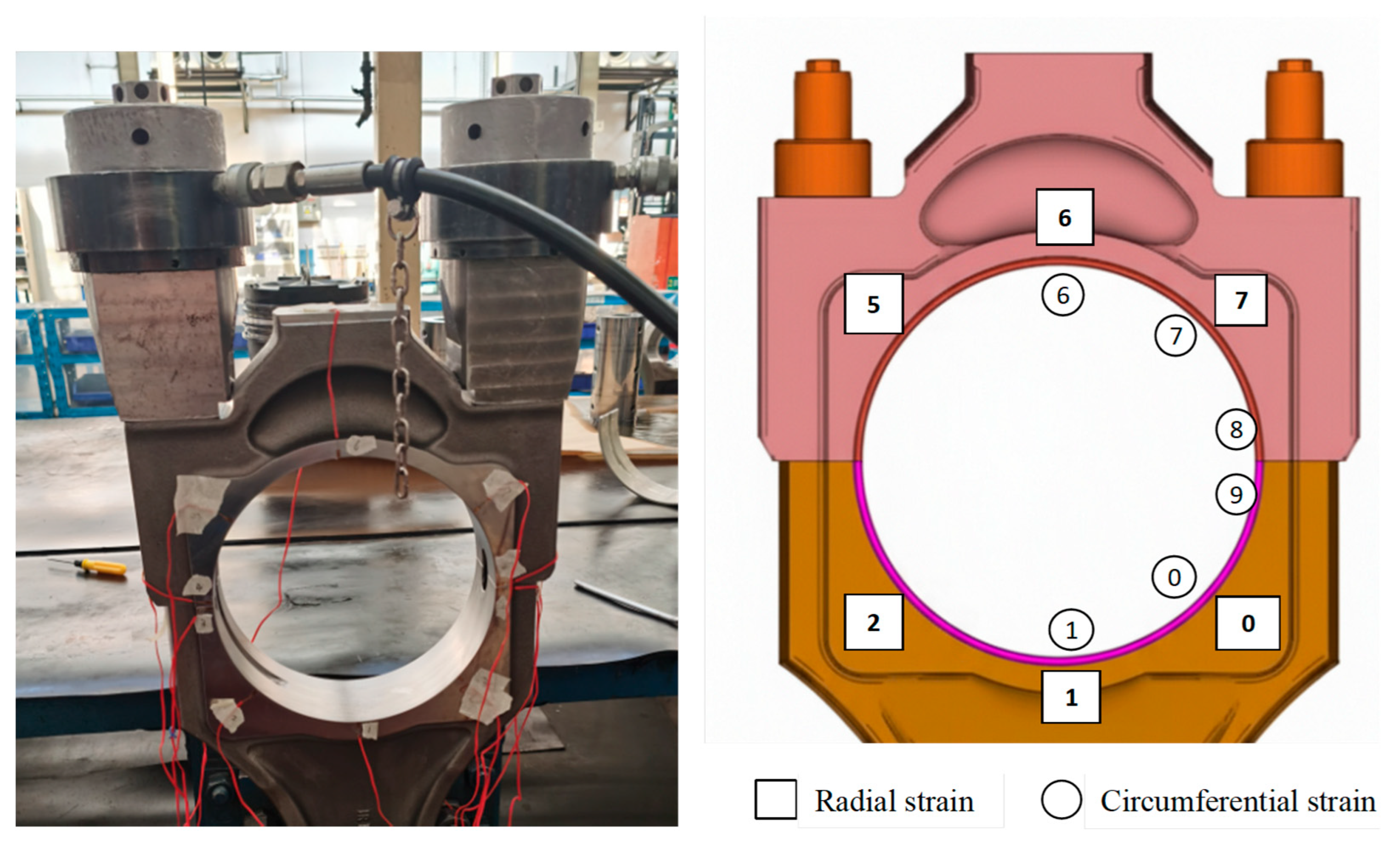
Actual assembly stresses were measured using uniaxial strain gauges. Gauges 0/1/2/5/6/7 were placed on the big-end bore to capture radial compressive strain, while gauges 0/1/6/7/8/9 were placed on the bearing side-face to measure circumferential strain, as shown in Figure 2. The test compared new and used bearings (B8, A1) to evaluate the impact of long-term operation on the contact state as shown in Table 2. The main differences among the “new bearing”, “B8 bearing”, and “A1 bearing” lie in their different excess heights, while the thicknesses of the bearing bushes are very close.

2.4. Dynamic Deformation FEA

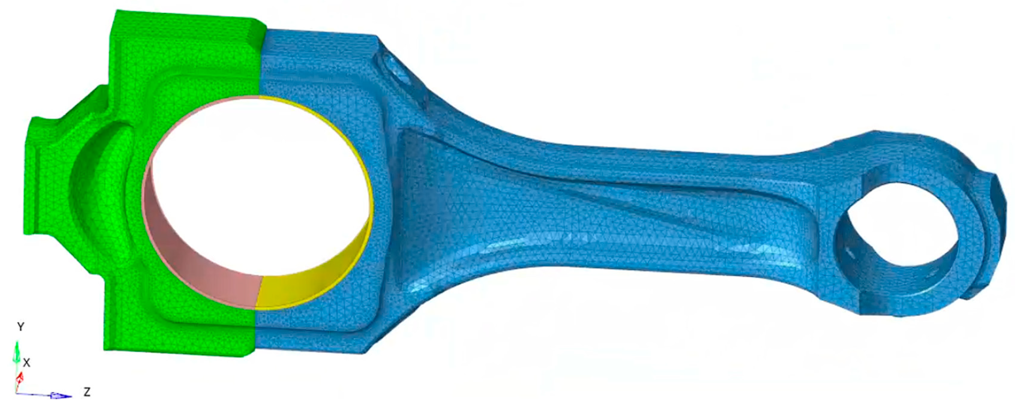
To investigate the deformation characteristics of the connecting rod big-end during engine operation, a high-fidelity FEA model was established, as illustrated in Figure 3. The model encompasses the rod shank, big-end housing, bearings, and bolts, with material properties summarized in Table 3. The rod shank and big-end housing were discretized using second-order tetrahedral elements, while hexahedral elements were employed for the bearings to ensure a one-to-one node correspondence at the interface between the bearing and the big-end bore. A minimum element size of 2 mm was maintained at critical regions such as fillets and the bearing body. Transient dynamic loads—including reciprocating inertia forces, rotational inertia forces, and rotational acceleration loads—were applied to the respective elements at each crank angle. Concurrently, the interaction force between the crankshaft and the bearing was assigned to the surface elements of the bearing. This model was utilized to quantify the big-end deformation under various combinations of bolt preload and interference fit (crush height), thereby identifying the critical factors governing structural distortion [30].
In addition to the structural deformation analysis, the contact state at the interface between the bearing back-face and the big-end bore was evaluated from a tribological perspective. The interface was modeled using surface-to-surface contact elements with frictional constraints, allowing the identification of stick–slip behavior during the deformation cycle.
According to classical fretting theory, the transition from full stick to partial slip and gross slip depends on the ratio between tangential force and normal contact pressure. Therefore, the calculated back-face pressure and the dynamic deformation (out-of-roundness) of the big-end bore were used to determine whether the interface remains in a stable stick regime or enters a fretting regime. This approach provides a tribological interpretation of the structural deformation results.

3. Results and Discussion

3.1. Design Range of Back-Face Pressure

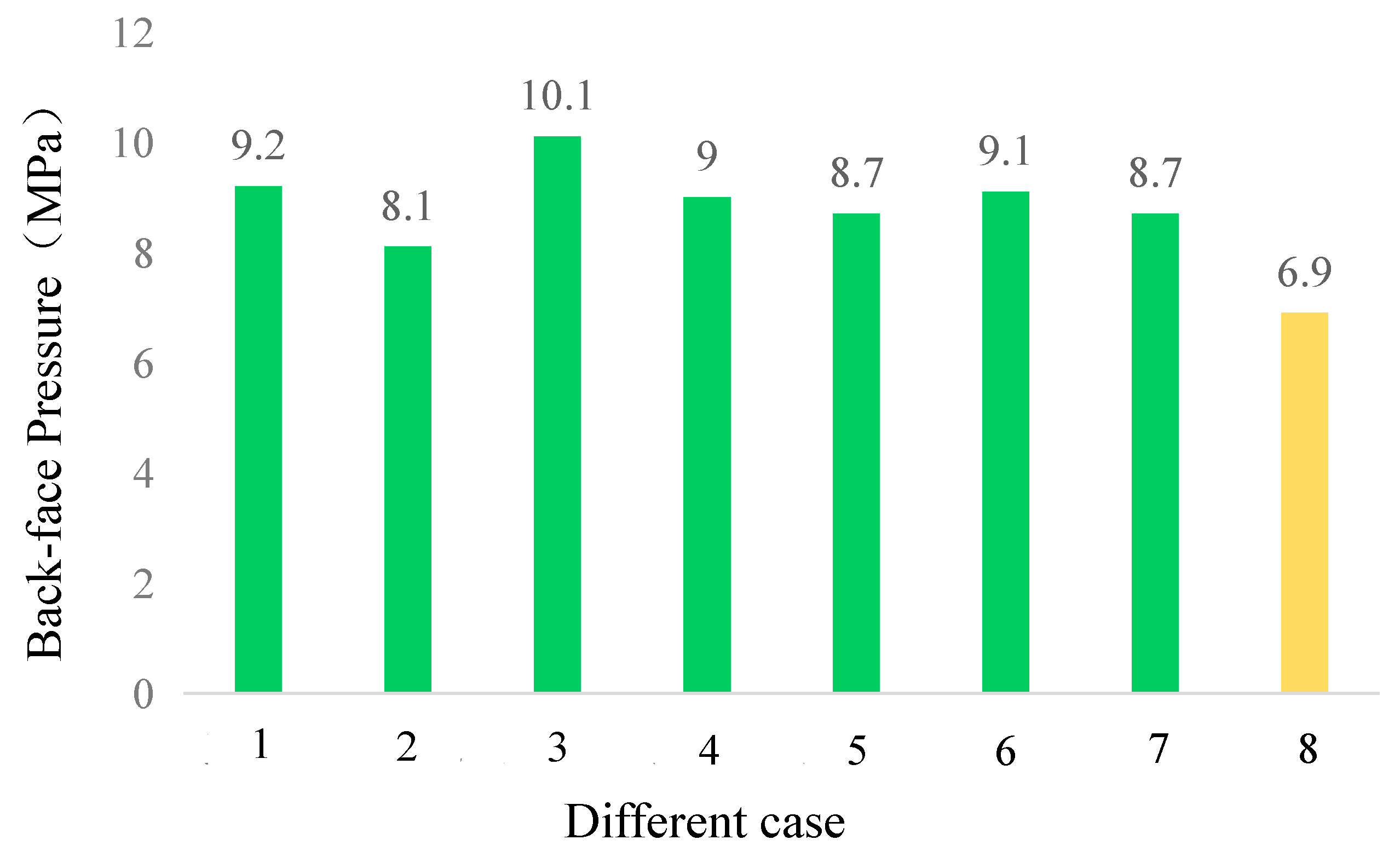
Calculations were performed for various tolerance combinations of the big-end bore diameter and the bearing crush height for this EDG model, with the results summarized in Table 4. Case 1, 2, 3 and 4 correspond to four combination methods involving the upper and lower tolerance limits of the connecting rod bore diameter and the design tolerance limits of the bearing bush excess height. Cases 5, 6 and 7 represent combinations of the measured bore diameters of connecting rods and the measured excess heights of bearing bushes from three on-site applications. Case 8 is an extreme combination scenario featuring the upper limit of the connecting rod bore diameter, the lower limit of the bearing bush excess height, and a preload of 461 kN. It can be observed that the designed back-face pressure of the connecting rod bearing ranges from 8.1 MPa to 10.1 MPa, while the circumferential stress (hoop stress) of the bearing shell falls within the range of 215 MPa to 268 MPa. Maintaining sufficient radial contact stress, or back-face pressure, is a critical prerequisite for preventing fretting wear between the bearing back and the housing bore. Although no explicit international standards currently define the design range for bearing back-face pressure, it is a widely accepted engineering guideline that a minimum pressure of 7 MPa should be maintained [18]. For comparison, the design range for the back-face pressure of connecting rod bearings in another medium-speed diesel engine of similar power rating used in NPPs is 12.5 MPa to 15.5 MPa. Consequently, while the designed back-face pressure of the investigated EDG model satisfies the general industry requirements, there remains a significant margin for optimization and enhancement.
In addition to the dimensional tolerances of the big-end bore and the bearing shell, the bolt preload significantly influences the back-face pressure. During the engine design phase, a “boring” process is typically performed after the initial assembly of the connecting rod bolts to mitigate bore distortion induced by the preload, thereby ensuring the circularity of the big-end bore. However, deviations in the actual preload during final assembly can still alter the effective bore diameter, subsequently affecting the bearing seating pressure. For this EDG model, the connecting rod bolts are installed using a hydraulic tensioning process. Due to factors such as the precision of the hydraulic tensioner, operator repeatability, and the installation procedure, empirical data indicate that the minimum bolt preload can drop to approximately 461 kN—a 16.2% reduction compared to the design value of 550 kN. When the preload decreases from 550 kN to 461 kN, the bore diameter along the rod shank axis increases from 240.151 mm to 240.193 mm. This expansion of 0.042 mm exceeds the design tolerance of 0.029 mm for the big-end bore. Consequently, under an extreme combination (Case 8) involving the upper limit of the bore diameter tolerance, the lower limit of the bearing crush height, and a reduced bolt preload of 461 kN, the back-face pressure further deteriorates to 6.9 MPa (as shown in Figure 4). This value falls below the recommended design limit of 7 MPa suggested in the literature [18].

3.2. Experimental Validation of Assembly Stress

Strain gauges were utilized to perform a comparative analysis of the back pressures exerted on the bearing shells affixed to the same connecting rod, comparing a newly installed set with a previously used set. In particular, a detailed comparative assessment of circumferential stress was conducted between the B8 bearing shell, which had been in service for approximately 4.5 years, and a brand-new spare bearing shell. The measurement results are systematically presented in Table 5.
Based on the measured data, the maximum and minimum circumferential stresses recorded for the B8 bearing shell are 266 MPa and 177 MPa, respectively. In contrast, the corresponding values for the new bearing shell are 230 MPa and 186 MPa. The deviations in the maximum and minimum circumferential stresses between the new bearing shell and the B8 bearing shell are calculated to be 44.3 MPa and 88.2 MPa, respectively. These findings conclusively demonstrate that the new bearing shell exhibits markedly superior uniformity in stress distribution compared to its older counterpart.
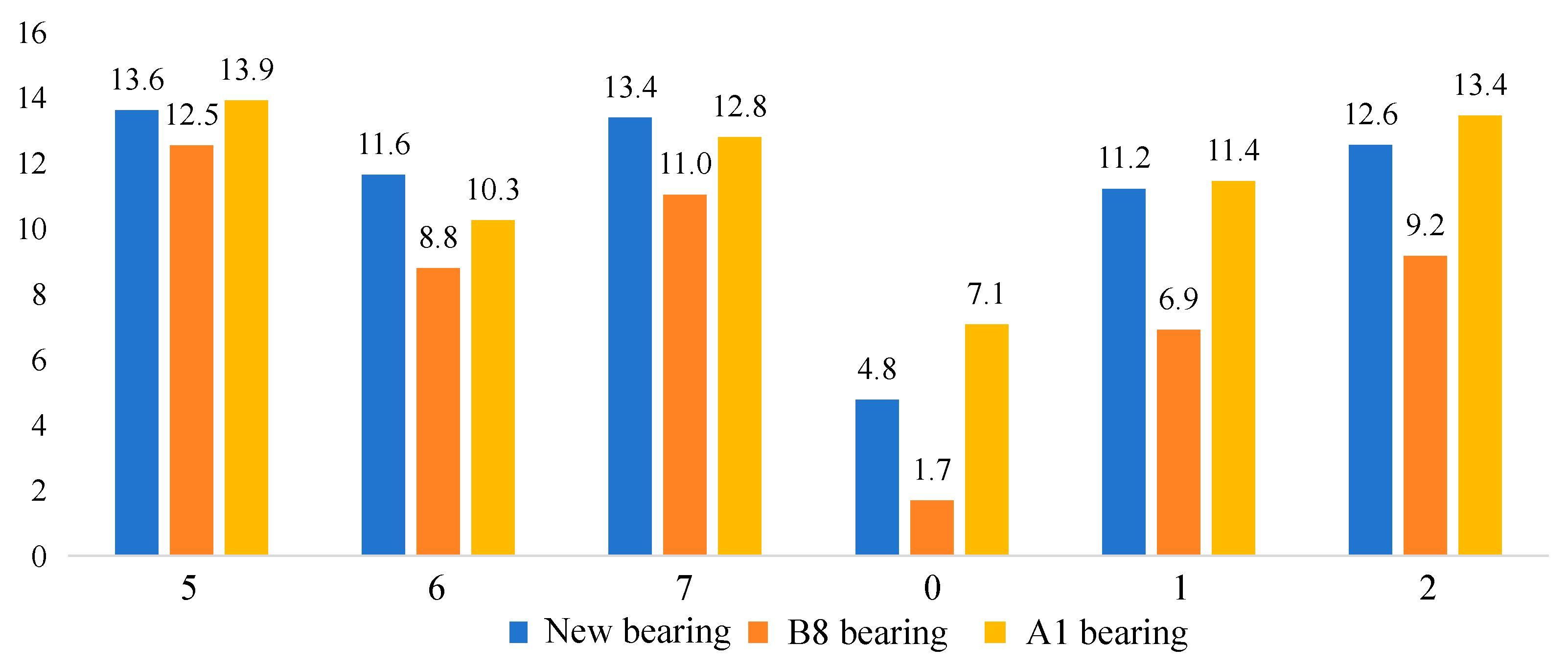
The factors leading to uneven pressure distribution on the bearing bush include: the uniformity of contact at the joint surface between the upper and lower bearing bushes, the position of oil groove openings on the bearing bush, and the actual pre-tightening force of the connecting rod bolts, among others. Comparative measurements of radial stress were conducted on B8 and A1 bearing shells in addition to a new spare bearing shell using uniaxial strain gauges on a test bench, with the measurement results depicted in Figure 5. The back-pressure values corresponding to the new bearing shell and the B8 bearing shell at measurement points 0, 1, and 2 (located on the upper half-side of the large end of the connecting rod) are 7.1 MPa, 11.4 MPa, and 13.4 MPa and 1.7 MPa, 6.9 MPa, and 9.2 MPa, respectively. Meanwhile, the back-pressure values corresponding to the new bearing shell and the B8 bearing shell at measurement points 5, 6, and 7 (located on the lower half-side of the large end of the connecting rod) are 13.9 Mpa, 10.3 Mpa, and 12.8 MPa and 12.5 MPa, 8.8 MPa, and 11.0 MPa, respectively. Despite having nearly identical relief height data, the new bearing shell generates significantly higher back-pressure within the bore of the large end of the connecting rod compared to the old B8 bearing shell. For the A1 bearing shell, the measured back-pressure values at measurement points 0, 1, and 2 are 4.8 MPa, 11.2 MPa, and 12.6 MPa, respectively, while those at measurement points 5, 6, and 7 are 13.6 MPa, 11.6 MPa, and 13.4 MPa, respectively. Due to its larger relief height, the A1 bearing shell also exhibits higher back-pressure than both the new bearing shell and the B8 bearing shell.

3.3. Calculation of Deformation at the Large End of the Connecting Rod

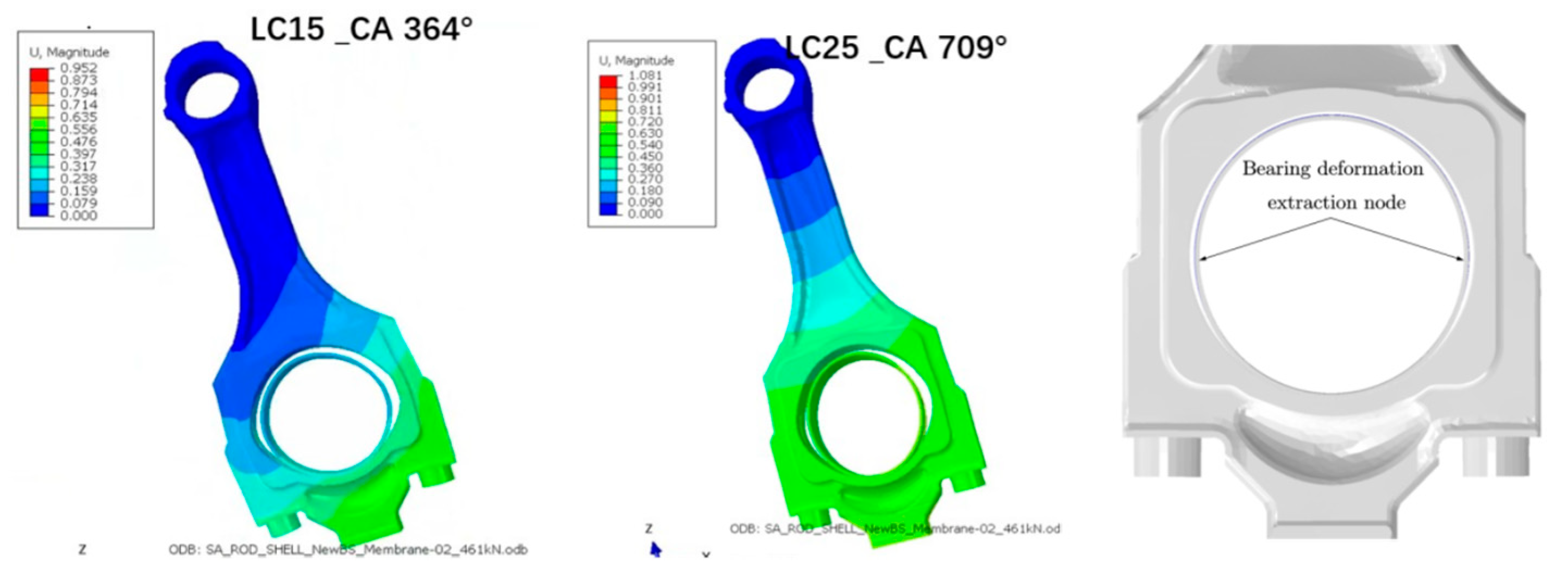
Figure 6 illustrates the deformation contour plots of the large end of the connecting rod for this type of emergency diesel engine at the top dead centers of the power stroke and the exhaust stroke. It can be observed that the bore of the large end of the diesel engine’s connecting rod undergoes repetitive dynamic deformation characterized by “flattening-elongation” cycles during operation. Such deformation induces relative sliding between the connecting rod bearing shell and the bore of the large end of the connecting rod.
To investigate the magnitude of deformation at the large end of the connecting rod for this type of emergency diesel engine, this project calculated and extracted the horizontal deformation of the bore at the large end of the connecting rod under varying preloads of connecting rod bolts and different interference fits of bearing shells, as presented in Table 6. It can be observed that when the preload of the connecting rod bolt is 550 kN, the corresponding horizontal deformations for interference fits of 0.31 mm and 0.26 mm are 0.244 mm and 0.209 mm, respectively. When the preload of the connecting rod bolt is reduced to 461 kN, the corresponding horizontal deformations for interference fits of 0.31 mm and 0.26 mm are 0.274 mm and 0.238 mm, respectively. Therefore, a decrease in the preload of the connecting rod bolt from 550 kN to 461 kN leads to an increase in the deformation of the bore at the large end of the connecting rod. Specifically, when the interference fit is 0.31 mm, the deformation increases by 0.03 mm, and when the interference fit is 0.26 mm, the deformation increases by 0.029 mm.
Additionally, an increase in the interference fit of the bearing shell also results in an augmentation of deformation at the large end of the connecting rod. This is primarily because the additional interference fit consumes a portion of the bolt preload to overcome the interference, thereby reducing the preload acting on the joint surface of the bore at the large end of the connecting rod and subsequently increasing its deformation. When the rotational speed increases from 1000 r/min to 1060 r/min, the horizontal deformation increases by 0.013 mm, mainly due to the enhanced centrifugal force acting on the connecting rod, which in turn increases the load on the large end of the connecting rod. By comparing the deformation data in Table 6, it can be seen that at a preload of 550 kN and an interference fit of 0.31 mm, the horizontal deformation falls within the design clearance range of 0.24 mm to 0.359 mm. However, considering installation deviations in preload, a decrease in preload may lead to a further increase in deformation.
To further elucidate the dynamic deformation characteristics of the large end of the connecting rod in this type of diesel engine, a single crankshaft cycle was discretized into 26 load steps spanning from 0° to 720° (with 0° representing the intake top dead center). The roundness of the bore at the large end of the connecting rod (defined as the difference between the maximum circumscribed circle radius and the minimum inscribed circle radius within the same plane) was extracted for each load step to quantify the dynamic deformation. The results are presented in Table 7. It can be observed that at the intake top dead center (crankshaft angle of 719°), the roundness value of the large end of the connecting rod reaches its maximum of 0.295 mm, indicating significant elongation and a pronounced “out-of-round” phenomenon in the bore at this instant.

4. Discussion

4.1. Wear Characteristics Analysis

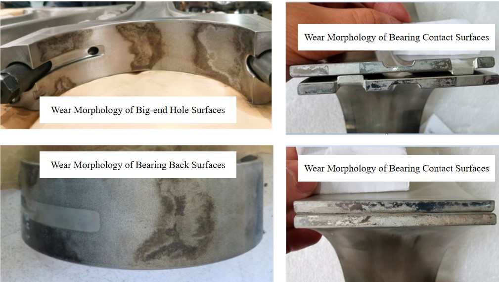
Multiple cases of connecting rod bearing shell failure have occurred in the emergency diesel engine of this model during operation. Upon disassembly and inspection, notable abnormal wear characteristics were observed on the back of the connecting rod bearing shells, as illustrated in Figure 7. It can be seen that after approximately five years of operation, wear marks are present on both the top and lateral sides of the bearing shell backs. In the top region of the bearing shell, which is subjected to peak combustion pressure, the wear is primarily attributed to the impact of cylinder pressure. However, wear on the lateral sides of the bearing shell indicates the occurrence of an “out-of-round” phenomenon in the large end of the connecting rod during operation. Additionally, distinct fretting wear marks are evident at the mating interface between the upper and lower bearing shells, further confirming significant dynamic deformation in the large end of the connecting rod in this diesel engine model.
Furthermore, due to the use of hydraulic installation tools for connecting rod bolt assembly, factors such as tool precision and operator repeatability can introduce variations in the preload force of the connecting rod bolts. According to actual measurements, under identical installation conditions (same tool and operator), the minimum preload force of the connecting rod bolts was approximately 461 kN, representing a 16.2% reduction compared to the design value of 550 kN. Therefore, reducing installation errors and improving the precision of preload force application remain crucial for mitigating the “out-of-round” phenomenon in the large end of the connecting rod.

4.2. Fretting Wear Mechanism at the Bearing Back-Face

Fretting wear occurs when two contacting surfaces experience small-amplitude oscillatory relative motion under high normal pressure. According to fretting theory, the contact interface can be divided into three regimes: stick regime, partial slip regime, and gross slip regime.
Under ideal assembly conditions, the bearing back-face is tightly clamped against the big-end bore by the combined effect of bolt preload and bearing interference (crush height). In this state, the interface remains in the stick regime, and no relative motion occurs.
However, when the bolt preload decreases or when the bearing loses its elastic recovery ability after long-term service, the back-face pressure decreases significantly. As shown in Table 4, a preload reduction from 550 kN to 461 kN decreases the back-face pressure from approximately 8–10 MPa to 6.9 MPa, which falls below the commonly accepted fretting suppression threshold of about 7 MPa. Under such conditions, the interface may enter a partial slip regime.
Meanwhile, the dynamic FEA results demonstrate that the big-end bore undergoes significant periodic deformation during engine operation. The maximum out-of-roundness reaches 0.295 mm at the intake top dead center. This deformation induces cyclic tangential displacement between the bearing back-face and the bore surface.
When the tangential displacement induced by the bore deformation exceeds the frictional resistance provided by the reduced normal pressure, the contact state transitions from partial slip to gross slip. In this regime, repeated micro-sliding leads to surface damage characterized by oxide debris formation, material removal, and typical fretting scars.
The wear morphology shown in Figure 7 is consistent with classical fretting characteristics, including localized wear patches and damage near the shell parting line. These observations confirm that the abnormal wear observed in the EDG connecting rod bearings is a typical fretting wear process driven by the coupling of structural deformation and insufficient contact pressure.

4.3. Corrective Actions

To resolve the fretting wear problem in the connecting rod bearing shells of this specific type of emergency diesel engine, the most fundamental approach involves redesigning the large-end structure of the connecting rod to enhance its stiffness and augment the designed back pressure of the bearing shells. Nevertheless, this solution demands substantial investment. Therefore, this study proposes an alternative methodology to alleviate fretting wear in the bearing shells, employing a strategy that integrates periodic verification of connecting rod bolt preload forces, scheduled replacement of connecting rods and bearing shells, and optimization of bearing shell back pressure. This strategy aims to minimize the extent of fretting wear and elevate the operational reliability of the connecting rod bearing shells.
Firstly, meticulous records of bolt preload force installation data are maintained, and a periodic verification framework for connecting rod bolt preload forces is established (with intervals of 1.5 years) to track trends in preload force degradation during engine operation. Should insufficient preload forces be identified, the entire connecting rod power assembly is replaced. Concurrently, a scheduled replacement protocol for connecting rod bearing shells and connecting rods is adopted (with a replacement cycle of 9 years) to preclude the exacerbation of fretting wear conditions resulting from prolonged service.
Finally, to maximize the interference fit of the connecting rod bearing shells, bearing shells with higher protrusion allowances are paired with connecting rods of larger bore diameters, while those with lower protrusion allowances are matched with connecting rods of smaller bore diameters. This pairing strategy avoids the mismatch of “large bore with small shell” and optimizes the back pressure exerted on the bearing shells, thereby enhancing their resistance to fretting wear.

5. Conclusions

In this study, the fretting wear mechanism of connecting rod big-end bearings in EDGs was investigated using a combined experimental and numerical approach. The following main conclusions are drawn:
(1)
Mechanism and Root Cause: The abnormal wear on the bearing back-face is identified as a typical fretting wear mechanism. Dynamic deformation of the big-end bore produces cyclic tangential displacement at the bearing–housing interface, while insufficient back-face pressure caused by bolt preload attenuation reduces frictional resistance. The coupling of these two factors drives the transition from a stick regime to partial slip and eventually to gross slip, leading to progressive fretting damage. FEA results reveal that at the intake top dead center, the dynamic roundness value peaks at 0.295 mm, triggering a transition from micro-slip to macro-slip that leads to interface degradation.
(2)
Key Influencing Factors: The interfacial stability is highly sensitive to the assembly state. A 16.2% reduction in bolt preload (from 550 kN to 461 kN) drops the back-face pressure to 6.9 MPa, falling below the 7 MPa safety threshold required to suppress fretting. Furthermore, experimental strain data confirm that the loss of bearing elasticity during long-term service significantly exacerbates this contact relaxation.
(3)
Engineering Guidelines: To ensure the safety of nuclear power plants, a dual-strategy maintenance approach is recommended: implementing a 1.5-year verification cycle for bolt preload and a 9-year mandatory replacement cycle for the connecting rod-bearing assembly. Additionally, optimizing the interference fit through selective assembly can effectively compensate for the stiffness deficit of the big end.

Author Contributions

Conceptualization, S.Z. and X.Y. (Xi Yang); methodology, S.Z. and J.Z.; software, Y.L.; validation, S.Z., X.Y. (Xi Yang) and Y.L.; formal analysis, Y.C. (Yi Cui) and S.Z.; investigation, P.H.; resources, X.Y. (Xiaohu Yang); data curation, Y.C. (Yi Cui); writing—original draft preparation, S.Z.; writing—review and editing, P.H.; visualization, Y.C. (Yinhui Che); supervision, P.H.; project administration, X.Y. (Xi Yang) and X.Y. (Xiaohu Yang); funding acquisition, X.Y. (Xi Yang). All authors have read and agreed to the published version of the manuscript.

Funding

This research received no external funding.

Data Availability Statement

Data is contained within the article. The original contributions presented in this study are included in the article. Further inquiries can be directed to the corresponding author.

Acknowledgments

The authors gratefully acknowledge the technical support and operational data provided by the engineers and staff at Suzhou Nuclear Power Research Institute and China Nuclear Power Operation Co., Ltd. for the model validation phase.

Conflicts of Interest

Author Pingsheng Hu was employed by the company China Nuclear Power Operation Co., Ltd. The remaining authors declare that the research was conducted in the absence of any commercial or financial relationships that could be construed as a potential conflict of interest.

References

  1. Zubair, M.; Zhijian, Z. Reliability data update method for emergency diesel generator of Daya Bay Nuclear Power Plant. Ann. Nucl. Energy 2011, 38, 2575–2580. [Google Scholar] [CrossRef]
  2. Marqusee, J.; Jenket, D. Reliability of emergency and standby diesel generators: Impact on energy resiliency solutions. Appl. Energy 2020, 268, 114918. [Google Scholar] [CrossRef]
  3. Juarez, C.; Rumiche, F.; Rozas, A.; Cuisano, J.; Lean, P. Failure analysis of a diesel generator connecting rod. Case Stud. Eng. Fail. Anal. 2016, 7, 24–31. [Google Scholar] [CrossRef]
  4. Deulgaonkar, V.R.; Ingolikar, N.; Borkar, A.; Ghute, S.; Awate, N. Failure analysis of diesel engine piston in transport utility vehicles. Eng. Fail. Anal. 2020, 120, 105008. [Google Scholar] [CrossRef]
  5. Vencl, A.; Rac, A. Diesel engine crankshaft journal bearings failures: Case study. Eng. Fail. Anal. 2014, 44, 217–228. [Google Scholar] [CrossRef]
  6. Takabi, J.; Khonsari, M.M. On the thermally-induced seizure in bearings: A review. Tribol. Int. 2015, 91, 118–130. [Google Scholar] [CrossRef]
  7. Jang, J.Y.; Khonsari, M.M.; Pascovici, M.D. Thermohydrodynamic seizure: Experimental and theoretical analysis. J. Tribol. 1998, 120, 8–15. [Google Scholar] [CrossRef]
  8. Jang, J.Y.; Khonsari, M.M.; Pascovici, M.D. Modeling aspects of a rate-controlled seizure in an unloaded journal bearing. Tribol. Trans. 1998, 41, 481–488. [Google Scholar] [CrossRef]
  9. Gebretsadik, D.W.; Hardell, J.; Prakash, B. Seizure behaviour of some selected Pb-free engine bearing materials under lubricated condition. Tribol. Int. 2017, 111, 265–275. [Google Scholar] [CrossRef]
  10. Jacques, K.; Voevodin, A.A.; Aouadi, S.; Murthy, N.; Berkebile, S.; Berman, D. Experimental investigations of scuffing of chromium nitride and diamond-like carbon protective coatings and AISI 52100 steel. Surf. Coat. Technol. 2025, 512, 132399. [Google Scholar] [CrossRef]
  11. El-Daher, C.C.; Kebir, H.; Bouvier, S.; Pont, M.; Hay, M. Prediction of fatigue damage and spalling in a multilayered journal bearing shell. Tribol. Int. 2022, 175, 107850. [Google Scholar] [CrossRef]
  12. Lang, O.R. Surface fatigue of plain bearings. Wear 1977, 43, 25–30. [Google Scholar] [CrossRef]
  13. Xia, Z.; Wu, D.; Zhang, X.; Wang, J.; Han, E.-H. Rolling contact fatigue failure mechanism of bearing steel on different surface roughness levels under heavy load. Int. J. Fatigue 2023, 179, 108042. [Google Scholar] [CrossRef]
  14. McCallion, H.; Lotfi, A. Tensile surface stresses and fatigue in plain journal bearings. Tribol. Int. 1992, 25, 247–257. [Google Scholar] [CrossRef]
  15. Wang, Q. Seizure failure of journal-bearing conformal contacts. Wear 1997, 210, 8–16. [Google Scholar] [CrossRef]
  16. Yin, J.; Liu, R.; Zhang, R.; Lv, B.; Meng, X. A new tribo-dynamics model for engine connecting rod small-end bearing considering elastic deformation and thermal effects. Tribol. Int. 2023, 188, 108831. [Google Scholar] [CrossRef]
  17. Dou, Q.; Luo, H.; Song, Y.; Zhang, Z.; Zhang, J. Failure analysis of diesel engine connecting rod big-end bearing wear considering coupled clearance lubrication joints. Eng. Fail. Anal. 2024, 169, 109136. [Google Scholar] [CrossRef]
  18. Han, Z.; Zhang, W.; Tan, S.; Xia, J.; Chen, X.; Yin, T.; Liu, D.; Liu, Z.; Cheng, S.; Meng, X. Tribological behavior and failure risk analysis of crankshaft-bearing systems in reciprocating compressors considering cantilever bias loading and crankshaft bending deformation. Eng. Fail. Anal. 2025, 182, 110160. [Google Scholar] [CrossRef]
  19. Vingsbo, O.; Söderberg, S. On fretting maps. Wear 1988, 126, 131–147. [Google Scholar] [CrossRef]
  20. Ramalho, A.; Celis, J.-P. Fretting laboratory tests: Analysis of the mechanical response of test rigs. Tribol. Lett. 2003, 14, 187–196. [Google Scholar] [CrossRef]
  21. Lee, H.; Mall, S. Some observations on frictional force during fretting fatigue. Tribol. Lett. 2004, 17, 491–499. [Google Scholar] [CrossRef]
  22. Nowell, D.; Dini, D.; Hills, D.A. Recent developments in the understanding of fretting fatigue. Eng. Fract. Mech. 2006, 73, 207–222. [Google Scholar] [CrossRef]
  23. Stefani, F.A.; Rebora, A.U. Finite element analysis of dynamically loaded journal bearings: Influence of the bolt preload. J. Tribol. 2002, 124, 486–493. [Google Scholar] [CrossRef]
  24. Stefani, F.A.; Rebora, A.U. A nonlinear structure-based elastohydrodynamic analysis method for connecting rod big-end bearings of high-performance engines. J. Tribol. 2004, 126, 664–671. [Google Scholar] [CrossRef]
  25. Ai, X.; Cheng, H.S.; Hua, D.; Moteki, K.; Aoyama, S. A finite element analysis of dynamically loaded journal bearings in mixed lubrication. Tribol. Trans. 1998, 41, 273–281. [Google Scholar] [CrossRef]
  26. Booker, J.F.; Boedo, F.; Bonneau, D. Conformal elastohydrodynamic lubrication analysis for engine bearing design: A brief review. Proc. Inst. Mech. Eng. Part C J. Mech. Eng. Sci. 2010, 224, 2648–2653. [Google Scholar] [CrossRef]
  27. Sahu, K.; Sharma, S.C.; Tomar, A.K. Effect of bearing shell deformation and ER fluid behavior on two-lobed slot-entry hybrid journal bearing. Proc. Inst. Mech. Eng. Part J J. Eng. Tribol. 2023, 238, 303–319. [Google Scholar] [CrossRef]
  28. Zhang, Y.; Chen, G.; Wang, L. Effects of thermal and elastic deformations on lubricating properties of the textured journal bearing. Adv. Mech. Eng. 2019, 11, 1687814019883790. [Google Scholar] [CrossRef]
  29. Zhang, L.S. Analysis of Assembly-Induced Stress in Crankshaft Bearings of Internal Combustion Engines. Railw. Locomot. Car 2011, 31, 170–176. [Google Scholar]
  30. Che, Y.; Zhang, M.; Chen, Q.; Ren, H.; Li, N.; Liu, S.; Cui, Y. Tribo-Dynamics and Fretting Behavior of Connecting Rod Big-End Bearings in Internal Combustion Engines. Lubricants 2025, 13, 376. [Google Scholar] [CrossRef]
Figure 1. The structure of connecting rod assembly.
Lubricants 14 00151 g001
Figure 2. The device of strain measurement and measurement points.
Lubricants 14 00151 g002
Figure 3. Meshing of the connecting rod assembly.
Lubricants 14 00151 g003
Figure 4. Bearing back-face pressure under various parameter combinations.
Lubricants 14 00151 g004
Figure 5. Back-face pressure of bearings at six different positions.
Lubricants 14 00151 g005
Figure 6. Deformation contour plots of crankshaft angle 364° and 709°.
Lubricants 14 00151 g006
Figure 7. Wear morphology on the back of the connecting rod bearing shell.
Lubricants 14 00151 g007
Table 1. Key parameters of the connecting rod assembly.
Primary ComponentsCorresponding Values
Big-end bore diameter tolerance240.15~240.175 mm
Crush height0.295~0.35 mm
Preload of bolts550 kN
Bearing width81 mm
Material of bearingCarbon steel 10
Material of connecting rod42CrMo4
Table 2. Bearings used for strain measurement.
Crush Height of Different BearingsValues
Crush height of new bearing0.643 mm
Crush height of B8 bearing0.648 mm
Crush height of A1 bearing0.683 mm
Table 3. Mechanical properties of materials.
ComponentsElastic Modulus (GPa)Poisson’s Ratio
Connecting rod2120.3
Connecting rod bolt2100.3
Connecting rod nut2120.28
Bearing lining alloy1100.33
Steel back2110.28
Table 4. Back-face pressure under different cases.
CaseBig-End Bore Diameter (mm)Crush Height
(mm)
Hoop Stress
(Mpa)
Back-Face Pressure (Mpa)Bolt Load
(kN)
1240.1790.352449.2550
2240.1790.2952158.1550
3240.150.3526810.1550
4240.150.2952399.0550
5240.150.3242318.7550
(B8 bearing)
6240.150.3422409.1550
(A1 bearing)
7240.150.3222308.7550
(New bearing)
8240.1790.2951846.9461
Table 5. Hoop stress of new bearing and B8 bearing.
Measurement Point678109
Hoop stress of B8 bearing (MPa)−207−216−177−216−203−266
Hoop stress of new Bearing (MPa)−200−219−186−198−214−230
Table 6. Deformation of the bore at the large end of the connecting rod under different combinations.
Preload of Bolts
(kN)
Interference Fit
(mm)
Speed
(r/min)
Horizontal Deformation
(mm)
Case 15500.3110000.244
Case 25500.2610000.209
Case 34610.3110000.274
Case 44610.2610000.238
Case 54610.2610600.251
Notes: The horizontal clearance range between the connecting rod bearing shell and the crankshaft is 0.24 to 0.359 mm.
Table 7. Roundness variation of the large end of the connecting rod.
Load StepCrankshaft Angle (°)Horizontal Deformation (mm)
LC0100.290
LC02300.272
LC03650.169
LC04730.155
LC051180.136
LC061520.101
LC071820.066
LC081920.069
LC092350.117
LC102790.207
LC112830.213
LC123050.238
LC133070.240
LC143400.178
LC153640.098
LC163940.159
LC174340.185
LC184390.183
LC194870.148
LC205130.107
LC215400.090
LC226100.152
LC236440.192
LC246750.189
LC257090.286
LC267190.295
Disclaimer/Publisher’s Note: The statements, opinions and data contained in all publications are solely those of the individual author(s) and contributor(s) and not of MDPI and/or the editor(s). MDPI and/or the editor(s) disclaim responsibility for any injury to people or property resulting from any ideas, methods, instructions or products referred to in the content.