A Method for Analyzing the Meshing Contact Performance of Real Tooth Surfaces of Spiral Bevel Gears


Abstract
1. Introduction
2. Construction of Digital Tooth Surface
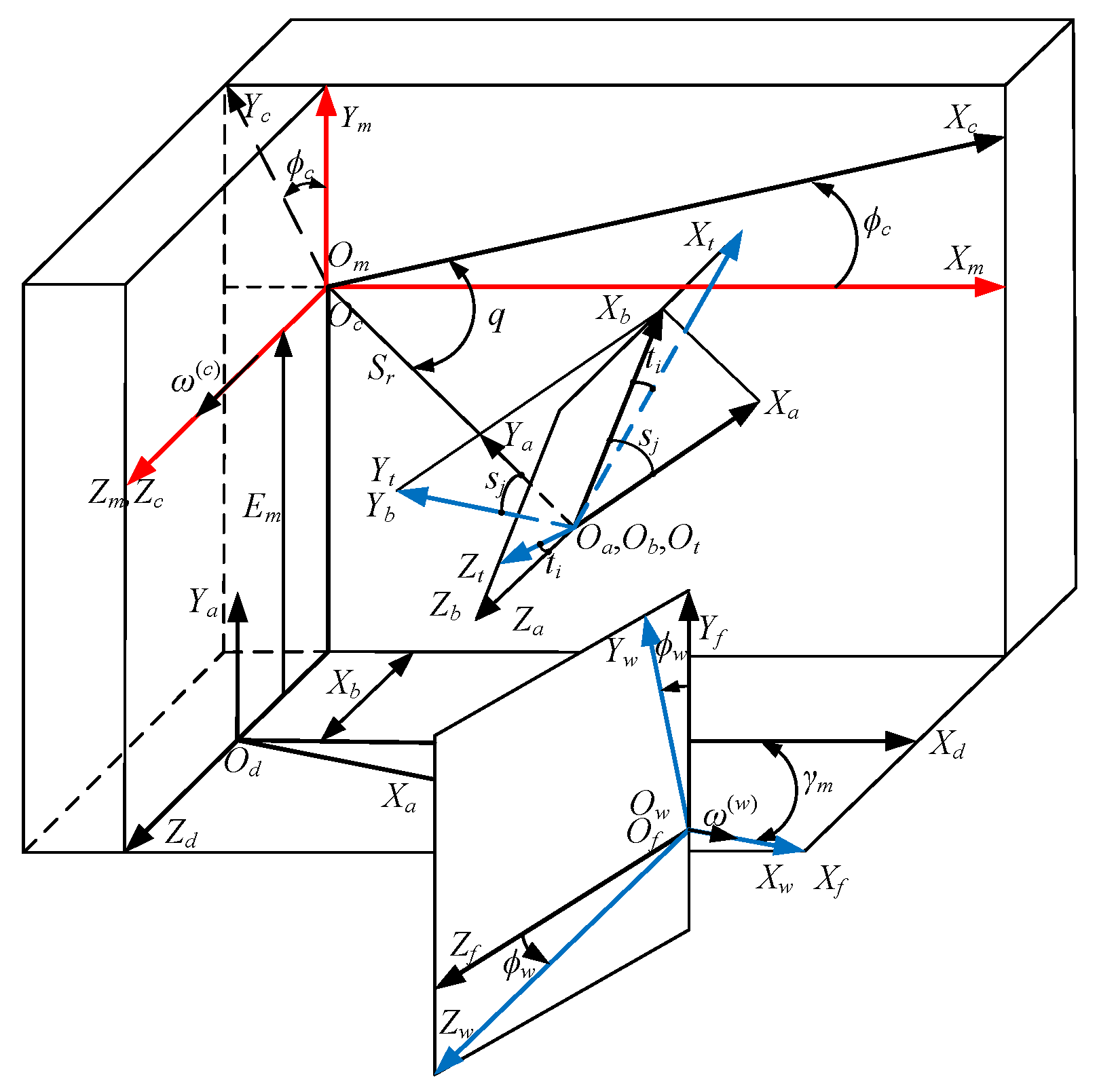
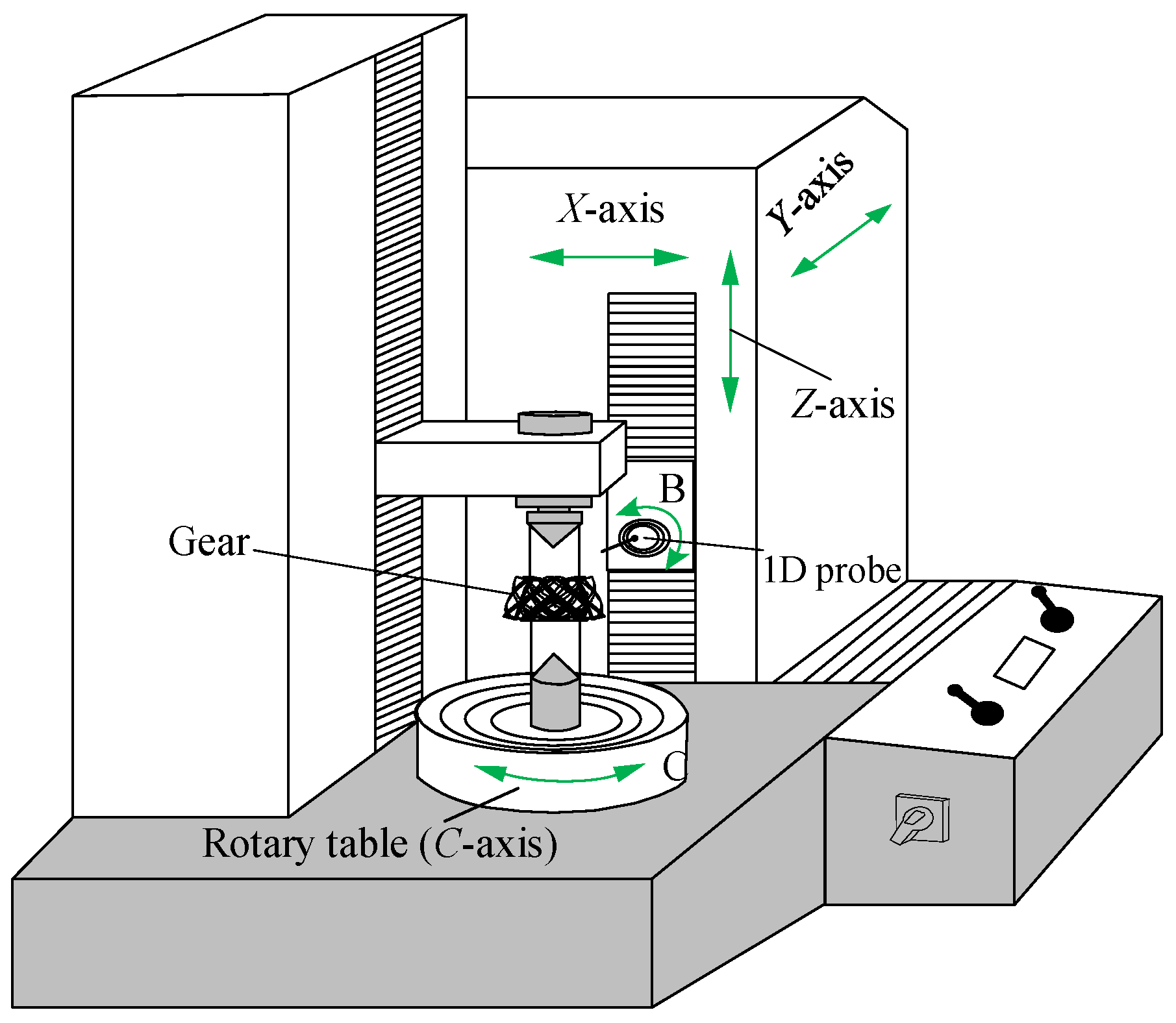
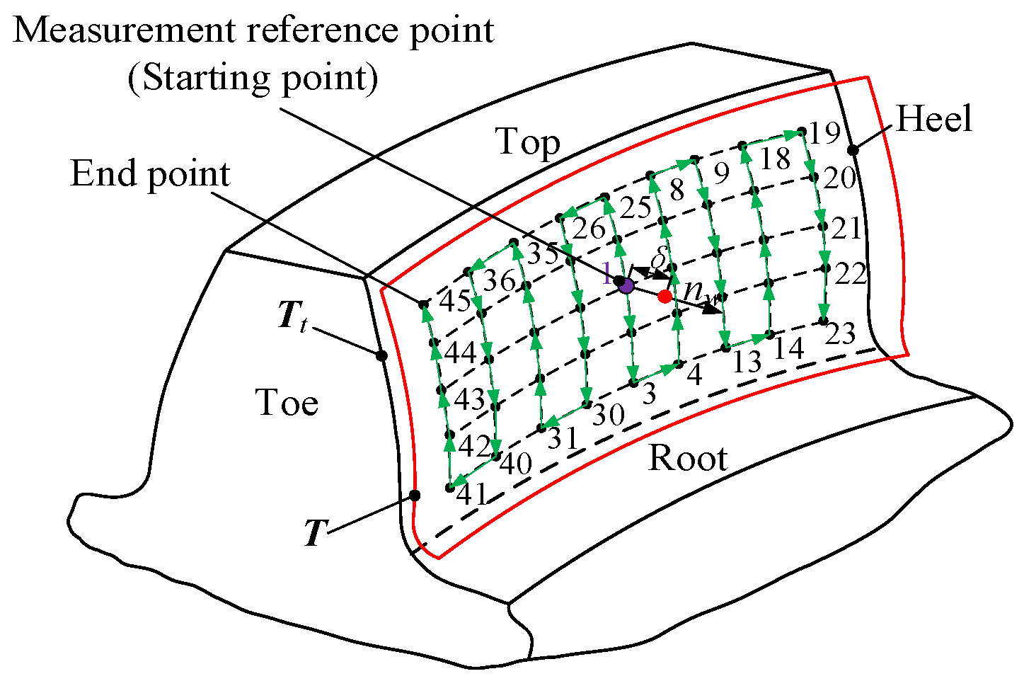
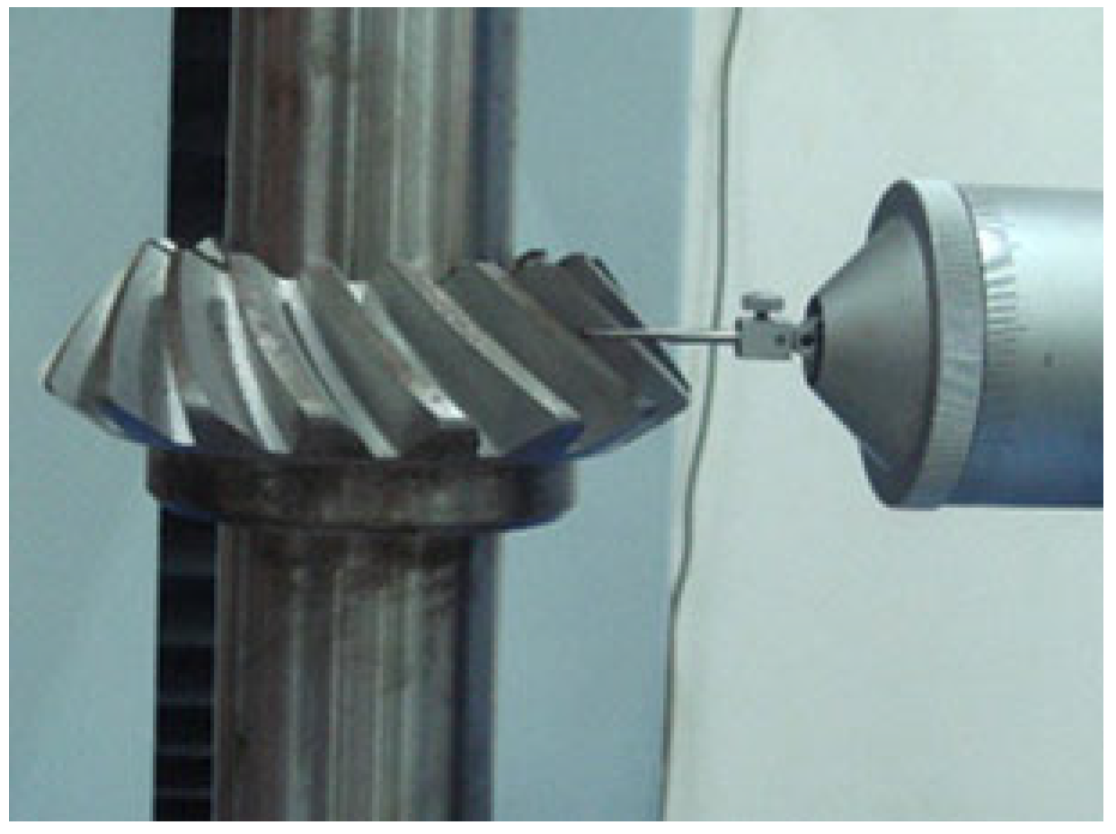
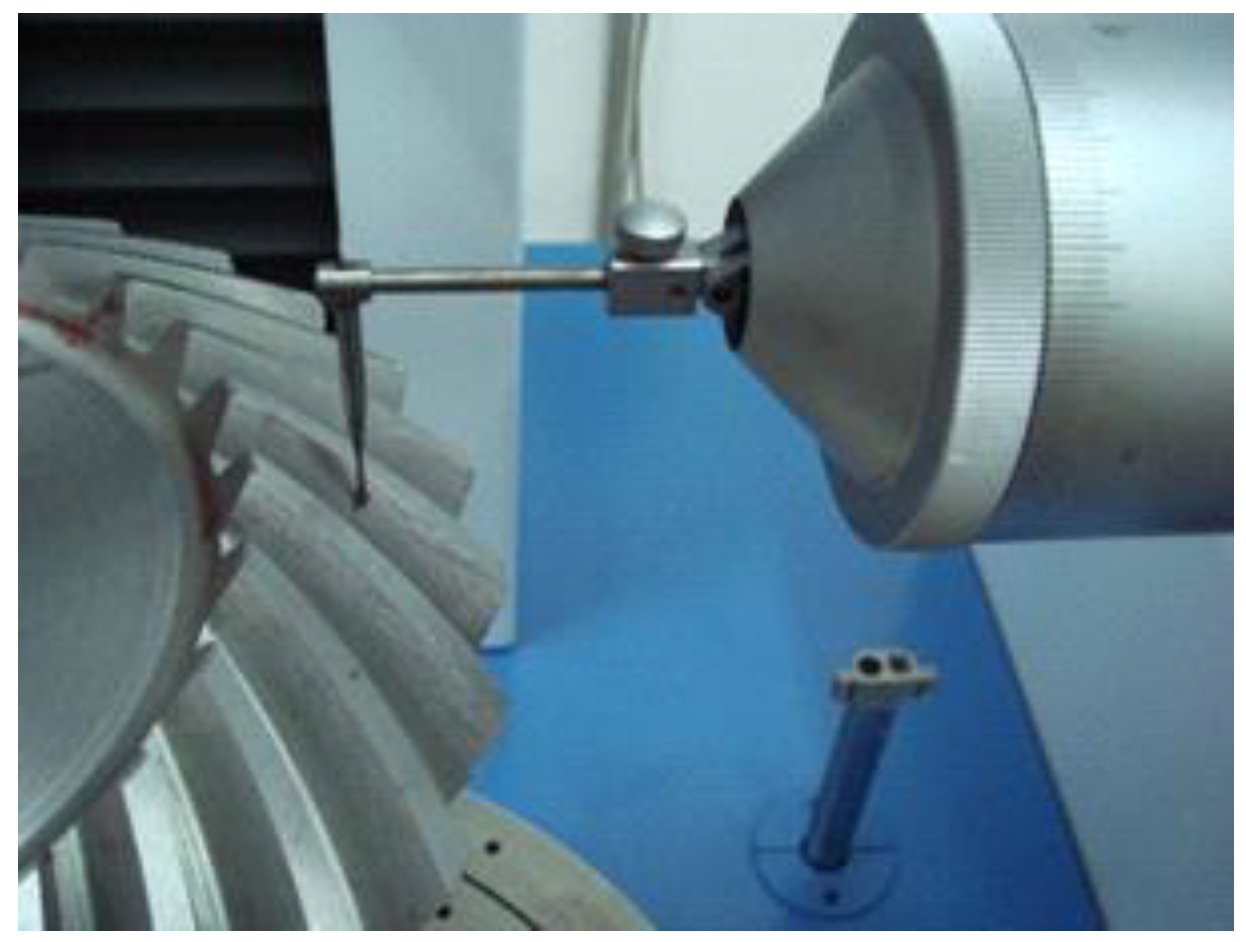
2.1. Discrete Data Acquisition for the Error-Containing Tooth Surface Based on a One-Dimensional Probe
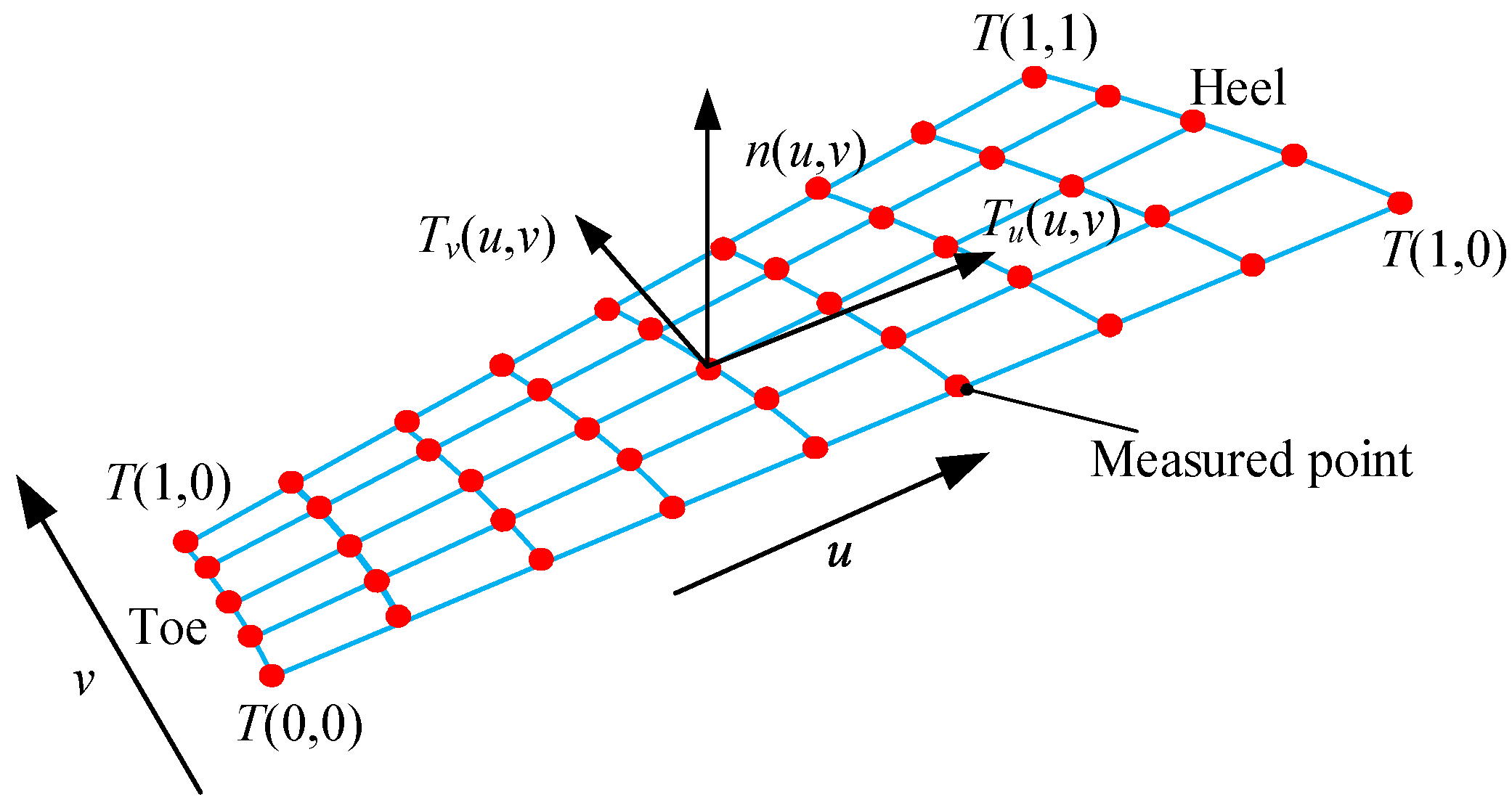
2.2. Reconstruction of the Digital Tooth Surface and Analysis of Its Accuracy
3. Tooth Contact Model and Determination of Meshing Parameters
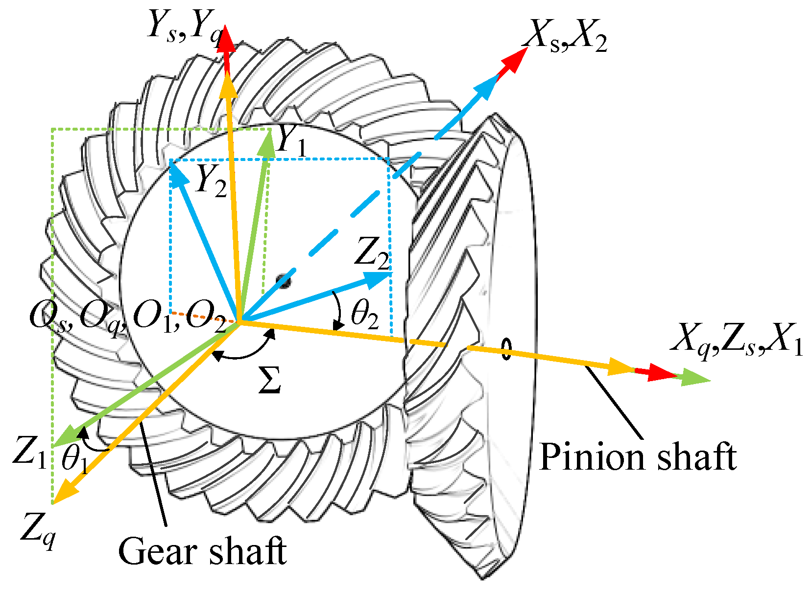
3.1. Construction of the Tooth Contact Model
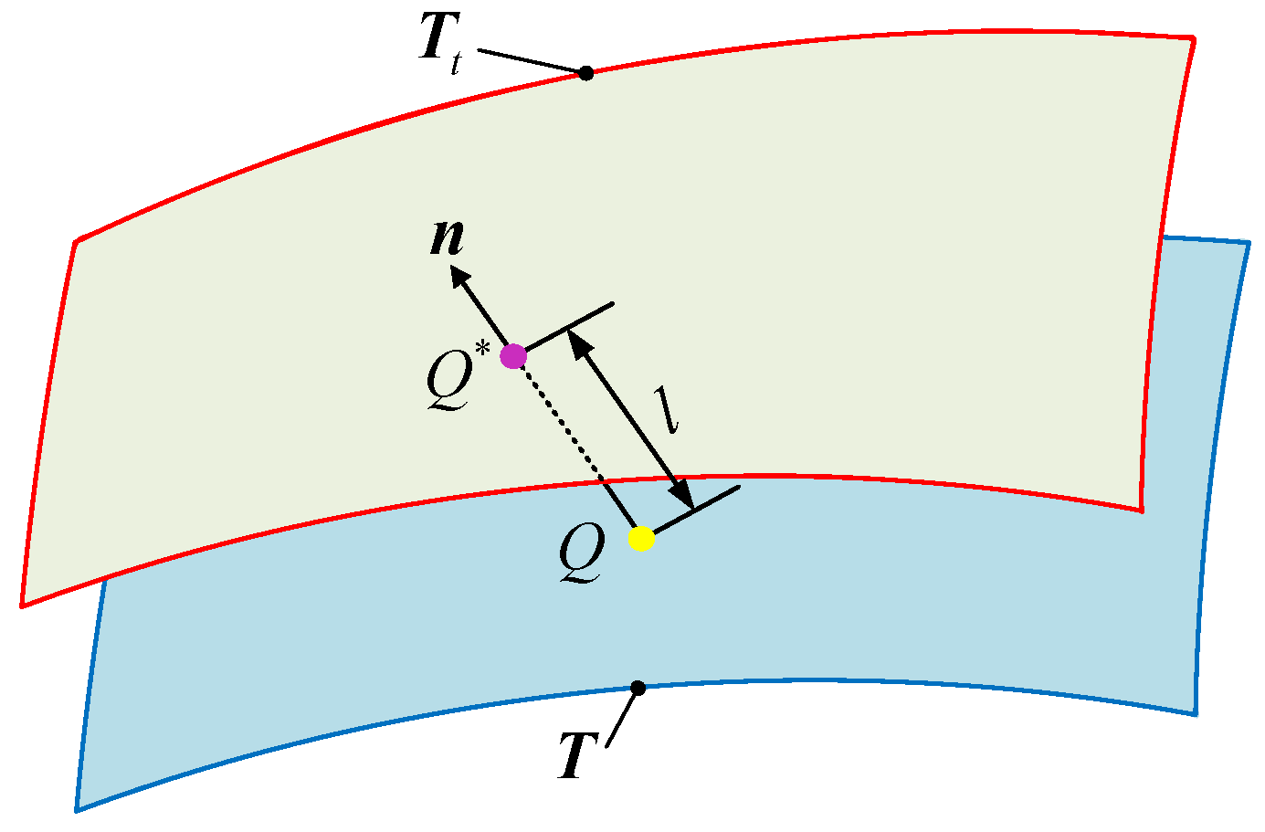
3.2. Acquisition of the Normal Distance Between Digital Tooth Surfaces
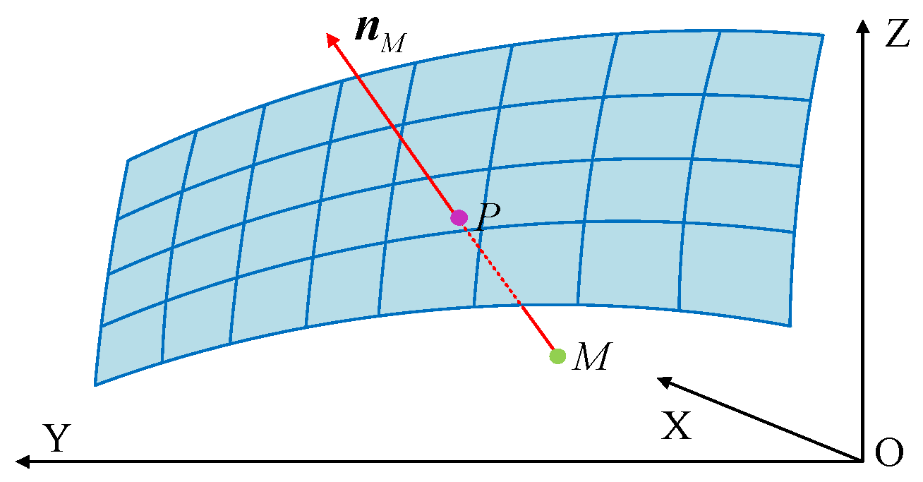
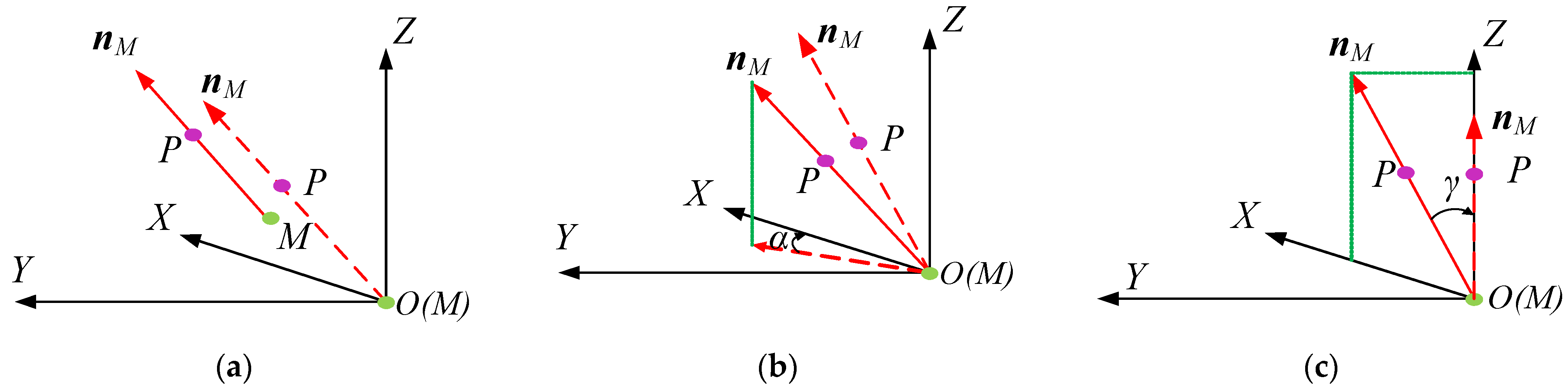
3.3. Determination of Actual Meshing Point Sequence and Contact Path
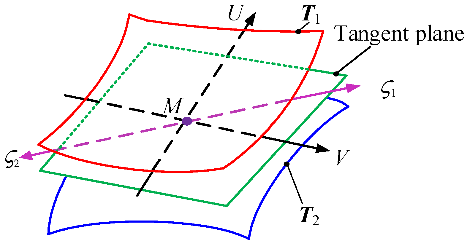
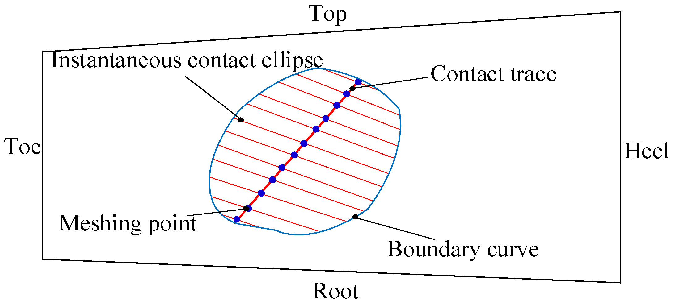
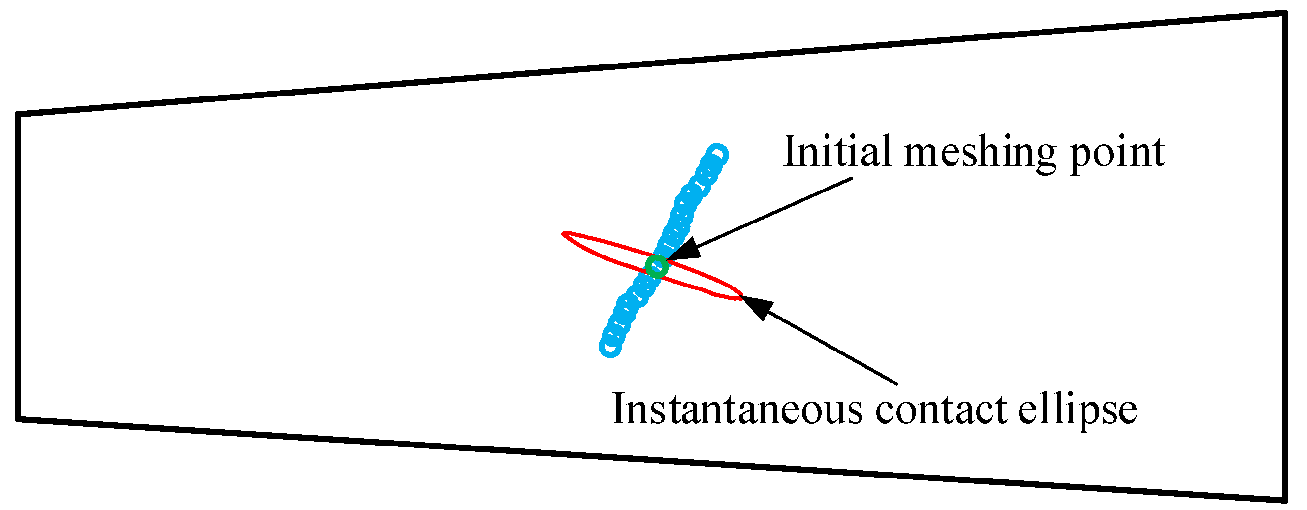
3.4. Solution of Instantaneous Contact Ellipse Based on Binary Search Method
- (1)
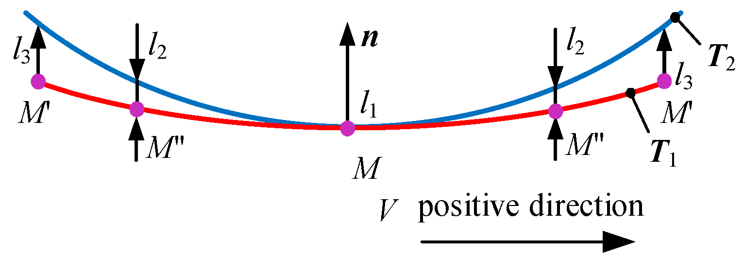
- If the normal distance l3 ≤ 0.00635 mm, then the point M′ on the pinion tooth surface corresponds to the V-direction endpoint M*. Consequently, the endpoint N* on the gear tooth surface T2 can also be determined using the same normal distance calculation method.
- (2)
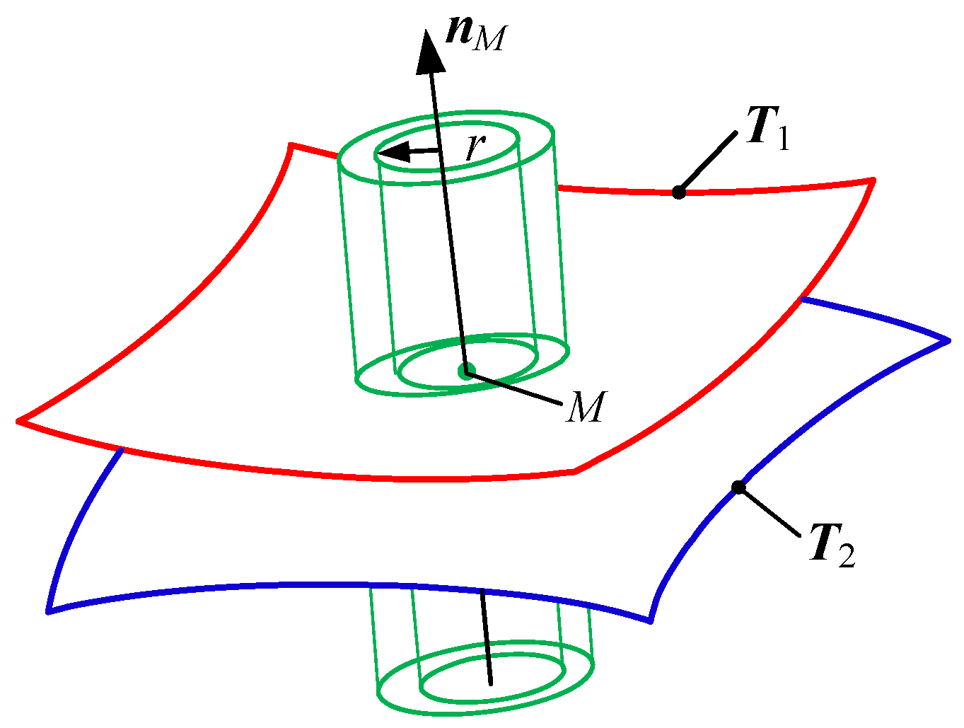
- If the normal distance l3 > 0.00635 mm holds, we determine the search direction according to the relationship between normal distance l2 and 0.00635 mm, where two distinct scenarios exist. First scenario: If l2 < 0.00635 mm, set l1 = l2, regard point M″ as point M, and take the midpoint M′ between M and M′. Then we assign l2 as the normal distance corresponding to this midpoint, after which we then re-evaluate the relationship between l2 and 0.00635 mm. Second scenario: If l2 > 0.00635 mm, then set l1 = l2, regard point M′′ as point M′ and we select the midpoint M′′ between M and M′. We set its corresponding normal distance to l2, and subsequently re-evaluate the relationship between l2 and 0.00635 mm. In both sub-cases, the iteration continues until the normal distance reaches 0.00635 mm, at which point the corresponding boundary endpoints M* on the pinion tooth surface T1 and N* on the gear tooth surface T2 of the instantaneous contact ellipse are determined.
- (1)
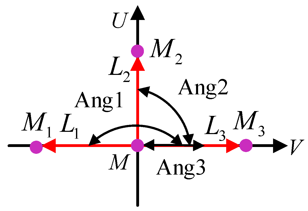
- If L1 ≤ L3, set Ang1 = Ang2 and Ang2 = (Ang1+ Ang3)/2; also set L1 = L2. To determine L2, first follow the direction tanAng2 to obtain the point on the pinion tooth surface where the normal distance equals 0.00635 mm. The length L2 is then determined by connecting this point to the meshing point M, after which the search termination condition is checked.
- (2)
- If L1 > L3, set Ang3 = Ang2 and Ang2 = (Ang1+ Ang3)/2; also set L3 = L2. The procedure for determining L2 is the same as in case (1).
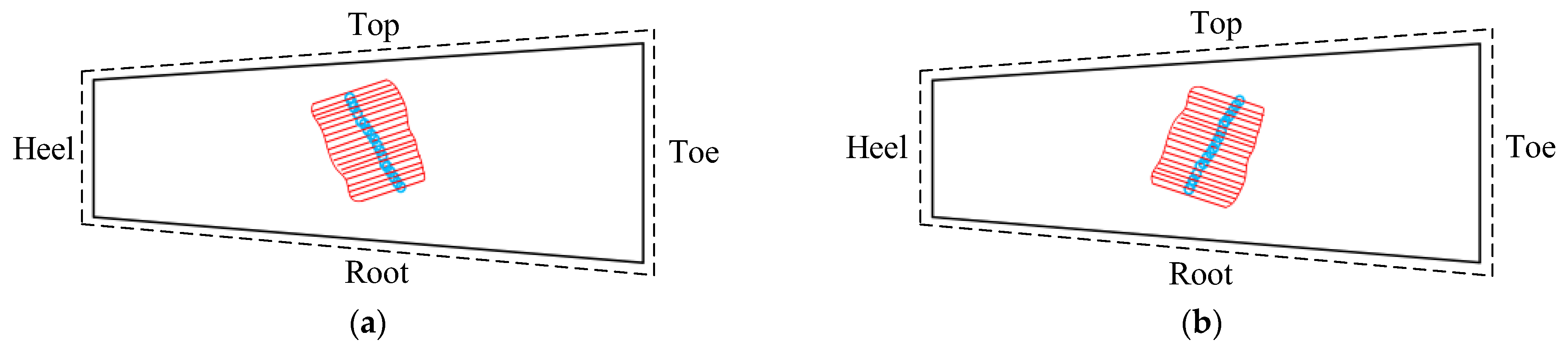
4. Digital Representation of Tooth Contact Performance
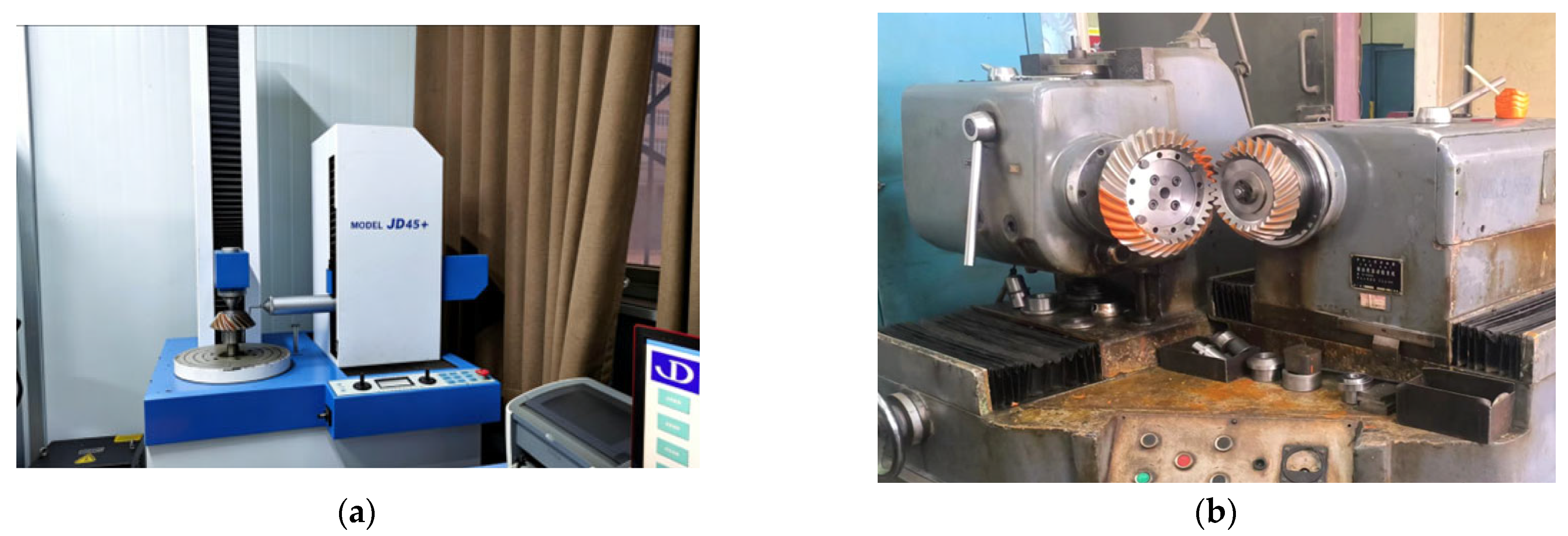
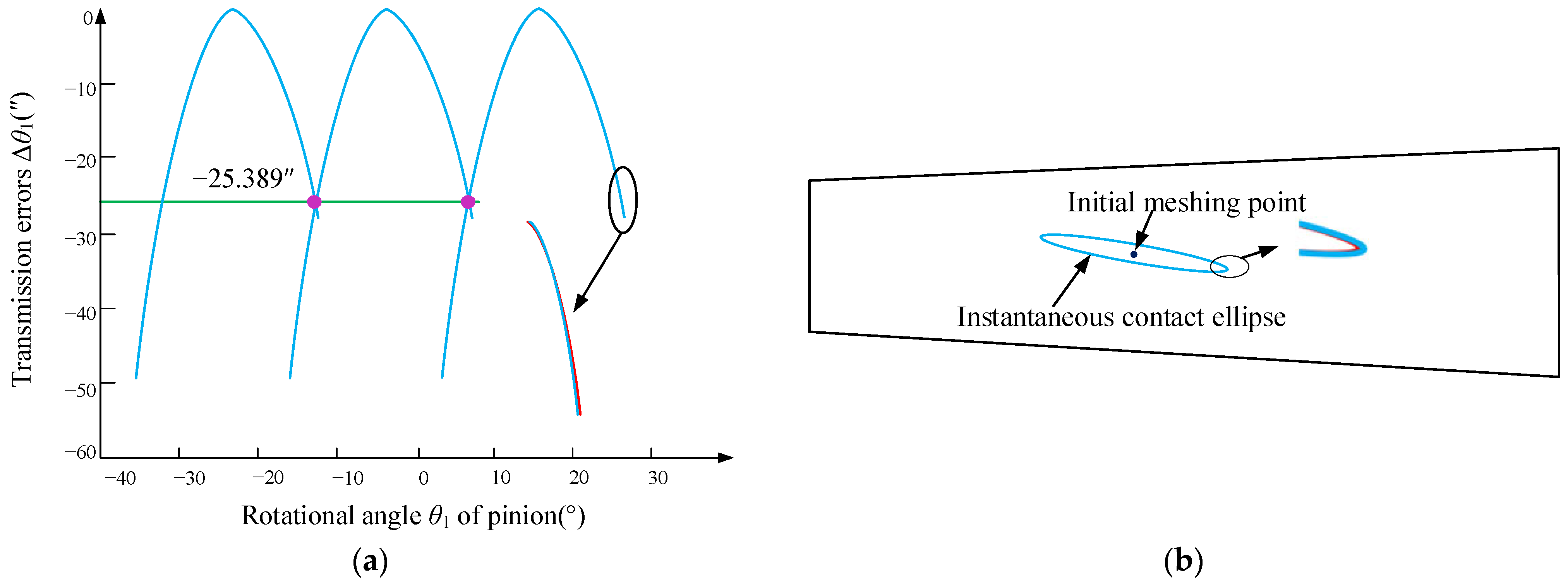
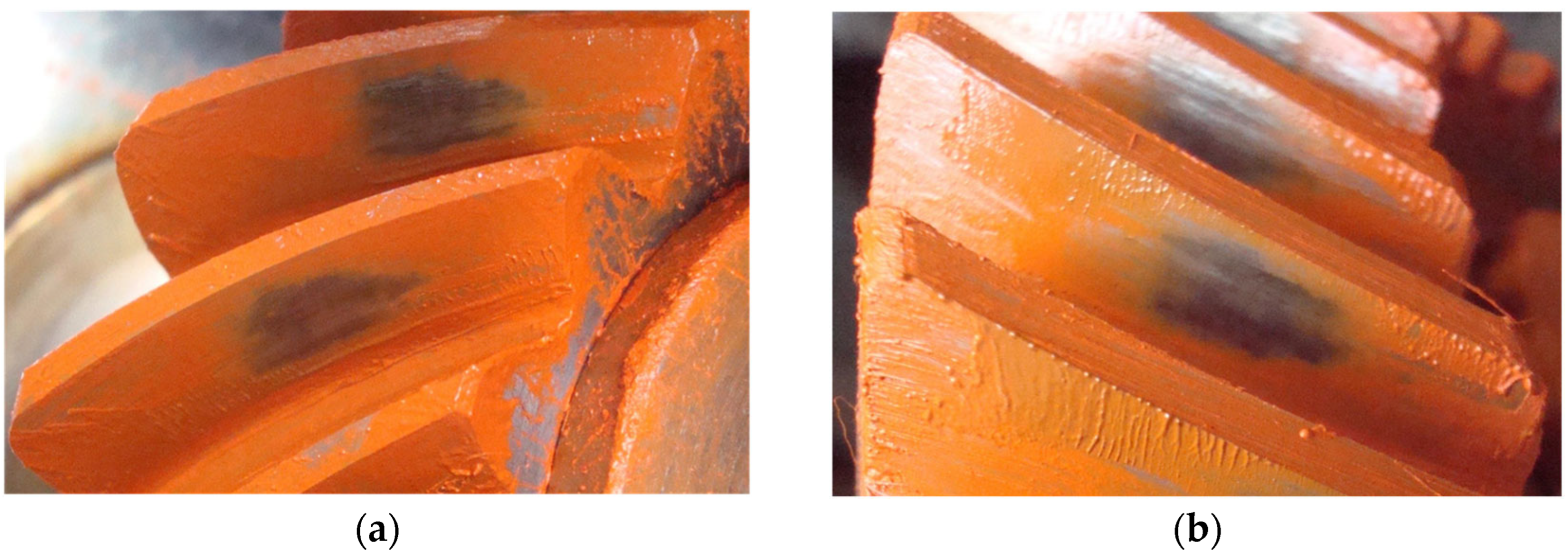
5. Experimental Verification
6. Conclusions
- Digital Reconstruction Strategy: A measurement path planning method for one-dimensional probes has been established. By constructing a tooth surface deviation model, high-precision digital tooth surfaces are reconstructed, serving as a reliable substitute for actual machined surfaces in the analysis.
- Simplified Contact Model: The traditional meshing model has been optimized by eliminating the mounting distance parameter. A novel solution for the instantaneous contact ellipse is proposed using a variable-radius cylindrical cutting method and a binary search algorithm, effectively bypassing the complexity associated with calculating principal curvatures and directions.
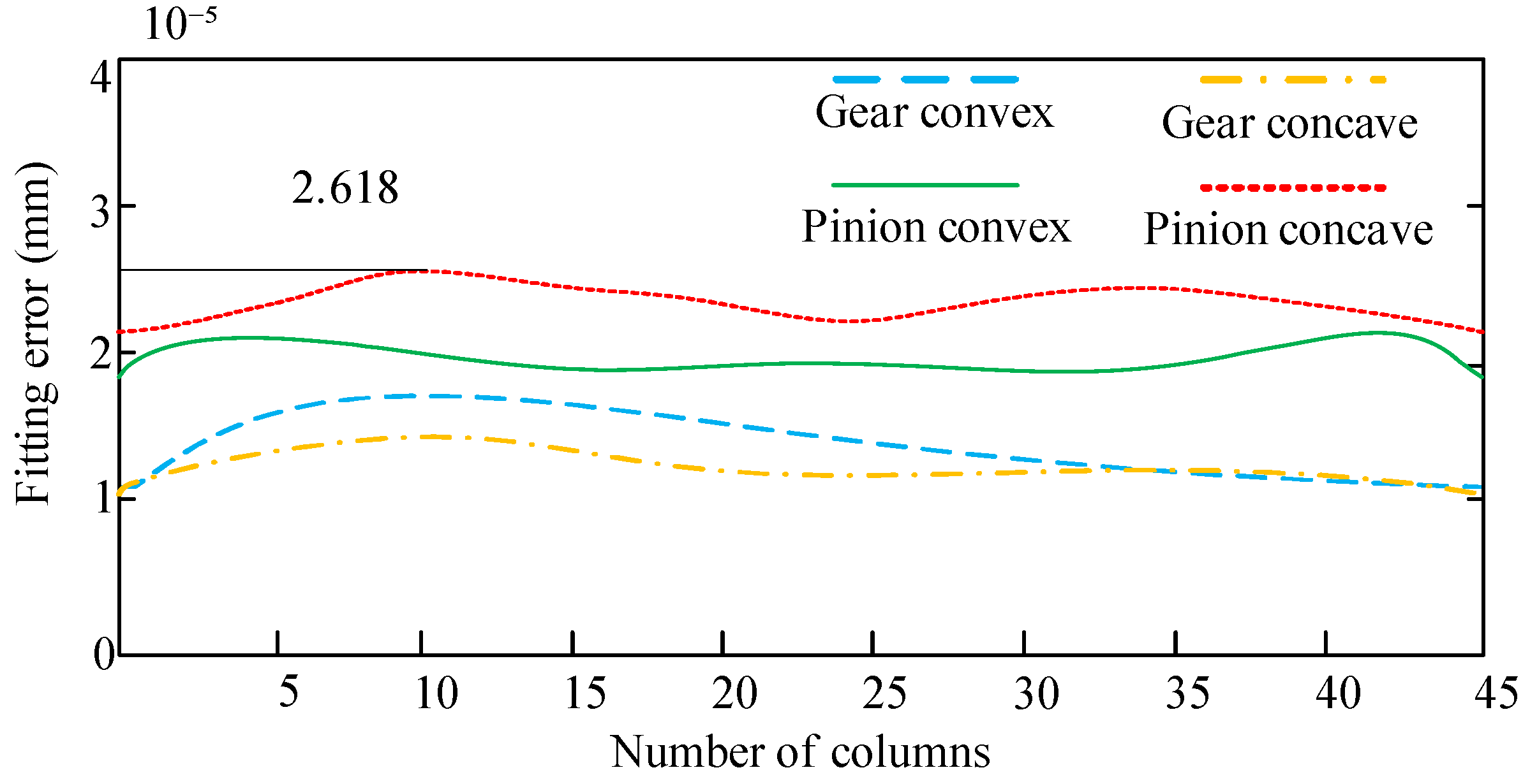
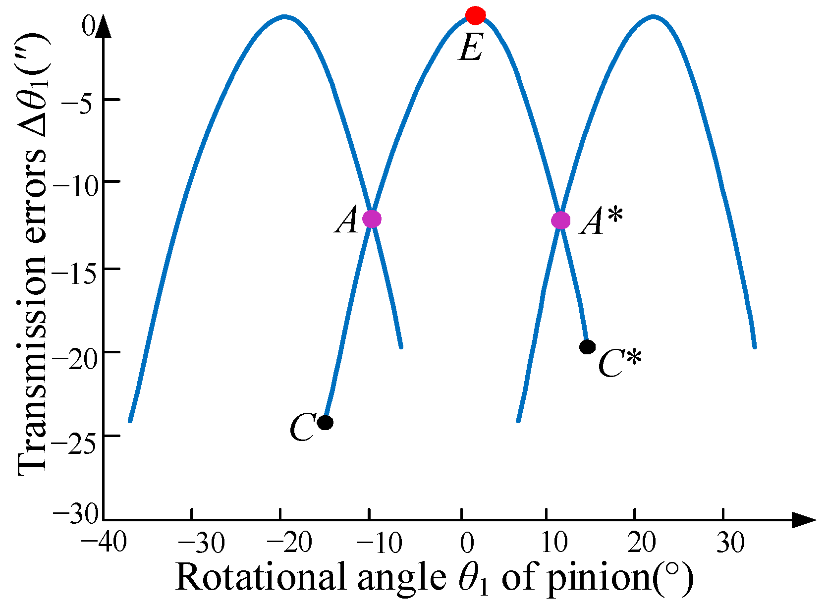
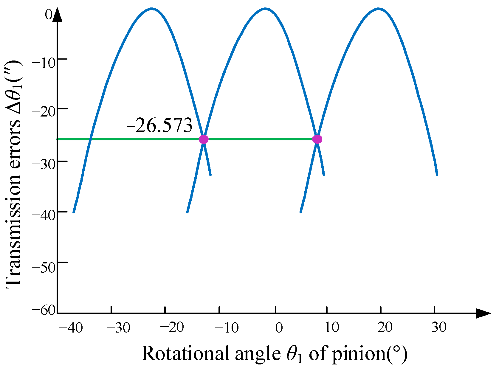
- Validation of Accuracy: The proposed method has been validated through gear measuring center data and rolling tests. The reconstruction error of the digital surface is negligible (10−9 mm), and the simulated transmission error curve deviates from the theoretical design by only 4.7%, thereby satisfying mechanical transmission standards (<5%).
- Practical Application: The digital contact patterns demonstrate strong agreement with the rolling test results in terms of location and shape, verifying that this method can accurately predict the meshing state of actual manufactured gears.
Author Contributions
Funding
Data Availability Statement
Conflicts of Interest
Nomenclature
| Mathematical symbol | Structured nomenclature |
| Ωj (j = 1, 2, …, m) | Set of machining parameters for the gear |
| (ϕt, ϕc) | Parametric coordinates of the tooth surface |
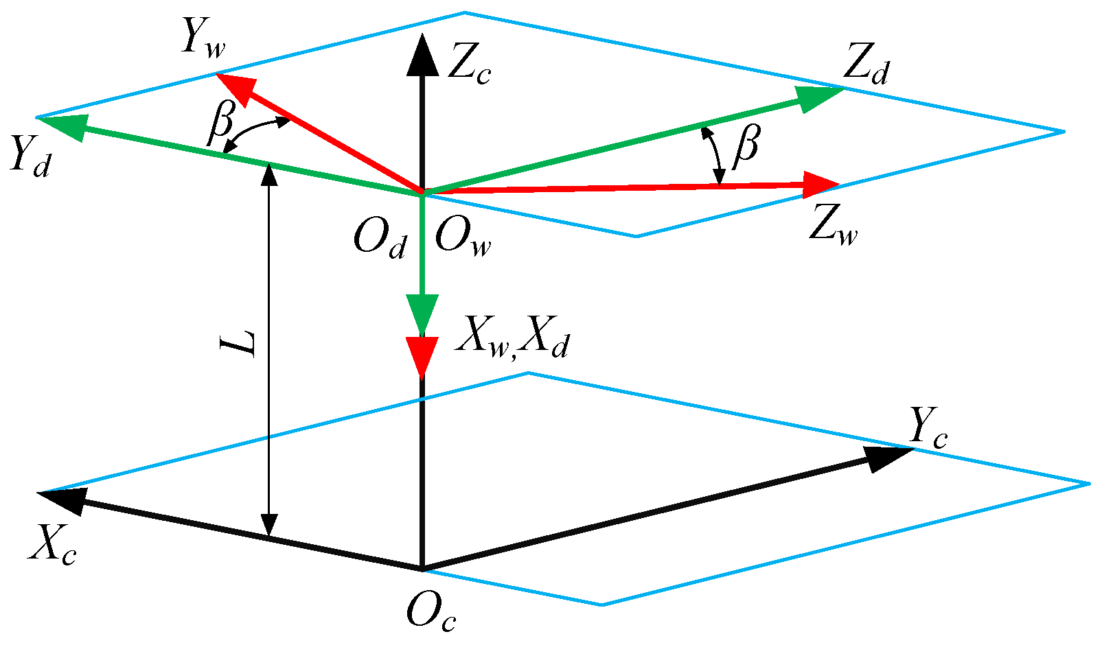
| Sw(Xw, Yw, Zw) | Workpiece coordinate system |
| Sc(Xc, Yc, Zc) | Measuring coordinate system |
| Sd(Xd, Yd, Zd) | Auxiliary coordinate system |
| Oc | Origin of the measuring coordinate system Sc |
| L | Axial distance between the origins of the workpiece coordinate system Sw and the measuring coordinate system Sc |
| β | Rotation angle of the gear |
| Hc, nc | Theoretical tooth surface and unit normal vector (Measuring System) |
| Hw, nw | Theoretical tooth surface and unit normal vector (Workpiece System) |
| δ | Tooth surface deviation |
| T(u, v) | Digital (reconstructed) tooth surface |
| Nip, Njq | B-spline basis functions of degree p and q |
| Wi,j | Control points of the NURBS surface |
| k | Order of the derivative of the B-spline basis function; order of the partial derivative vector in the u-direction of the digital tooth surface |
| p | Degree of the B-spline basis function |
| S(u,v) | General expression of the NURBS surface |
| Su,Sv | First-order tangent vectors of the digital tooth surface T(u, v) along the u- and v-directions, respectively |
| n | Unit normal vector of the digital tooth surface T(u, v) |
| l | Normal distance between surfaces |
| Q(xq, yq, zq) | Arbitrary point on the digital surface T |
| Q*(x*q, y*q, z*q) | Intersection point of the normal line of point Q with the theoretically designed surface Tt |
| θ1, θ2 | Rotation angles of the pinion and gear |
| Σ | Shaft angle |
| S1(X1, Y1, Z1) | Rotating coordinate system associated with the pinion |
| S2(X2, Y2, Z2) | Rotating coordinate system associated with the gear |
| Ss(Xs, Ys, Zs) | Fixed coordinate system |
| Sq(Xq, Yq, Zq) | Auxiliary coordinate system for meshing analysis |
| T1(u1, v1), T2(u2, v2) | Digital tooth surface of the pinion and Digital tooth surface of the gear |
| n1(u1, v1), n2(u2, v2) | Unit normal vector of the pinion’s digital tooth surface and Unit normal vector of the gear’s digital tooth surface |
| M(xM, yM, zM) | Arbitrary point on the pinion tooth surface T1 |
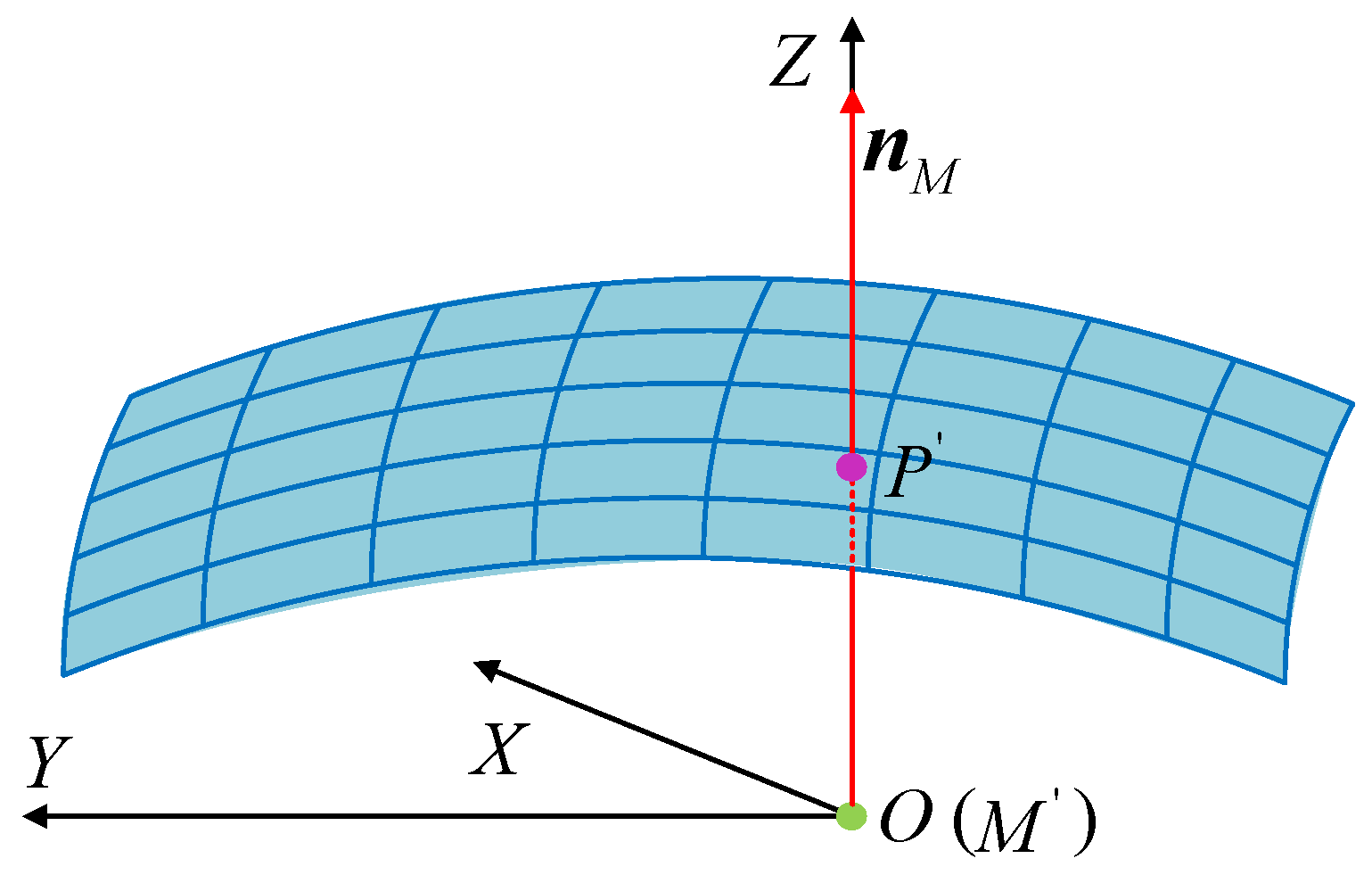
| nM | Unit normal vector of the pinion tooth surface T1 at point M |
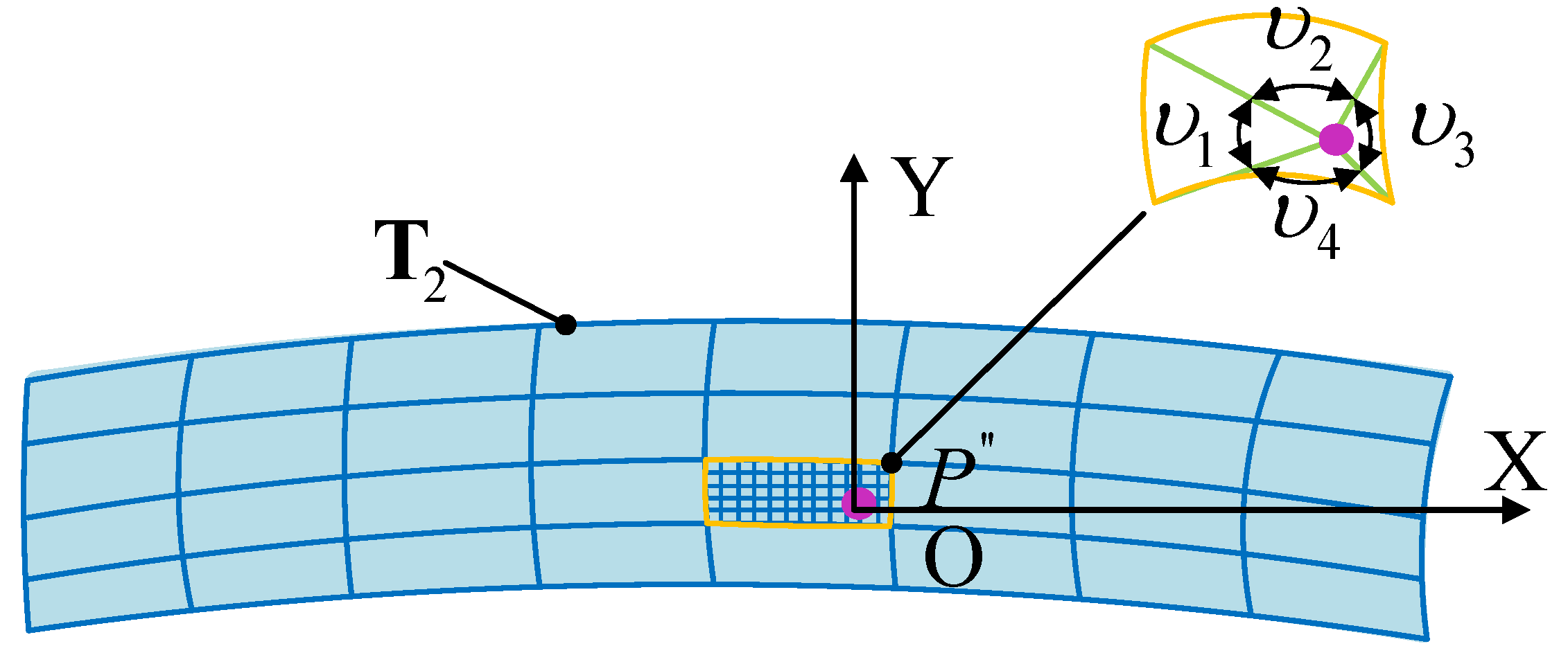
| P(xP, yP, zP) | Intersection point of the normal line nM with the gear tooth surface T2 |
| (uP, vP) | Parameters of the intersection point P on the gear tooth surface T2 |
| α | Rotation angle of the normal vector nM about the Z-axis |
| γ | Rotation angle of the normal vector nM about the Y-axis |
| P′(x′P, y′P, z′P) | Transformed intersection point of the normal vector nM with the gear surface after rigid translation and rotation |
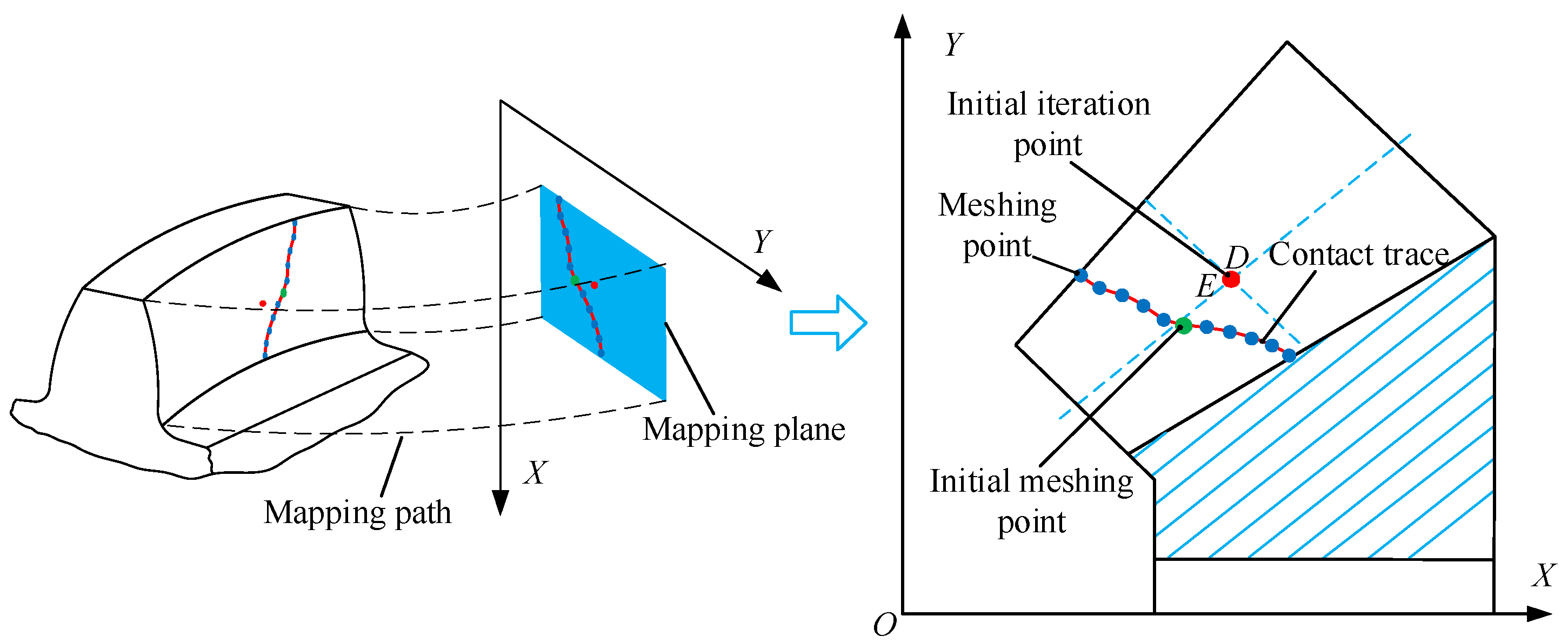
| D | Initial iteration point for determining the initial meshing point |
| E | Initial meshing point of the spiral bevel gear pair |
| Δθ2 | Gear rotation increment corresponding to the initial meshing point E |
| j (j = 1, 2, …, k) | Index of the meshing point in the sequence, where k represents the total number of meshing points |
| (u1(1), v1(1), u2(1), v2(1)) | Parameters of the j-th meshing point on the pinion and gear digital tooth surfaces |
| (xj, yj, zj) | Coordinates of the j-th meshing point before projection |
| (x*j, y*j) | Coordinates of the j-th meshing point on the axial cross-section projection plane |
| r | Radius of the variable-radius cylinder used to intercept the meshing tooth surfaces for obtaining the instantaneous contact ellipse |
| U, V | Axes of the two-dimensional coordinate system established on the tangent plane of the meshing point M |
| ς1, ς2 | Directions of the major and minor axes of the contact ellipse |
| M′ | Boundary point on the pinion tooth surface T1 |
| M′′ | Midpoint between the meshing point M and boundary point M′ |
| l1, l2, l3 | Normal distances at points M, M′′, M′, respectively |
| M*, N* | Boundary endpoint of the instantaneous contact ellipse on the pinion tooth surface T1 and Boundary endpoint of the instantaneous contact ellipse on the gear tooth surface T2 |
| a1 | Length of the semi-major axis of the instantaneous contact ellipse |
| Δθ | Transmission error of the spiral bevel gear pair at a meshing point |
| θ10, θ20 | Initial meshing rotation angle of the pinion and gear |
| Z1, Z2 | Number of teeth of the pinion and gear |
Abbreviations
| Abbreviation | Full Form |
| NURBS | Non-Uniform Rational B-Spline |
| CNC | Computer Numerical Control |
| CMM | Coordinate Measuring Machine |
| MPD | Maximum Positive Deviation |
| MND | Minimum Negative Deviation |
References
- Zhang, Y.; Zhu, L.; Gou, X. Calculation methods of load distribution ratio for spiral bevel gear. Int. J. Mech. Sci. 2023, 257, 108531. [Google Scholar] [CrossRef]
- Li, J.; Zhang, P.; Feng, L.; Yin, G.; Chen, Z.; Ma, W.; Xu, A.; Nie, S.; Zhang, H. Information description and integration of spiral bevel gear manufacturing process under networked manufacturing mode. J. Braz. Soc. Mech. Sci. 2019, 41, 234. [Google Scholar] [CrossRef]
- Shih, Y.; Sun, Z.; Lai, K. A flank correction face-milling method for bevel gears using a five-axis CNC machine. Int. J. Adv. Manuf. Technol. 2017, 91, 3635–3652. [Google Scholar] [CrossRef]
- Zhao, H.; Sheng, P. The measurement and evaluation method of global error of spiral bevel gear. Adv. Mater. Res. 2011, 204, 1299–1304. [Google Scholar] [CrossRef]
- Lin, H.; Keller, F.; Stein, M. Influence and compensation of CMM geometric errors on 3D gear measurements. Measurement 2020, 151, 107110. [Google Scholar] [CrossRef]
- Li, T.; Zhou, J.; Deng, X.; Li, J.; Xing, C.; Su, J.; Wang, H. A manufacturing error measurement methodology for a rotary vector reducer cycloidal gear based on a gear measuring center. Meas. Sci. Technol. 2018, 29, 75006. [Google Scholar] [CrossRef]
- Li, T.; Li, J.; Deng, X.; Yang, J.; Li, G.; Ma, W. A new digitized reverse correction method for hypoid gears based on a one-dimensional probe. Meas. Sci. Technol. 2017, 28, 125004. [Google Scholar] [CrossRef]
- Dai, Z.; Li, T.; Zhang, Y.; Zhou, J.; Zhang, R. A model construction and measurement method for tooth surface deviation of spiral bevel gear based on a one-dimensional probe. Meas. Sci. Technol. 2023, 34, 45001. [Google Scholar] [CrossRef]
- Liu, Y.; Fang, S.; Chen, Y.; Zhang, J. Compensation method for inclination errors in measurement results of tooth surface of spiral bevel gear. Math. Probl. Eng. 2021, 2021, 6617077. [Google Scholar] [CrossRef]
- Liu, Y.; Chen, Y.; Fang, S. A compensation method for the eccentricity and inclination errors of spiral bevel gear based on improved ICP algorithm. Adv. Mech. Eng. 2021, 13, 1069482992. [Google Scholar] [CrossRef]
- Zhou, L.; Fang, S.; Liu, Y.; Li, Y.; Taguchi, T.; Takeda, R. An alignment angle error compensation method of spiral bevel gear tooth surface measurement based on tooth surface matching. Meas. Sci. Technol. 2021, 32, 105020. [Google Scholar] [CrossRef]
- Cao, X.; Deng, X.; Wei, B. A novel method for gear tooth contact analysis and experimental validation. Mech. Mach. Theory 2018, 126, 1–13. [Google Scholar] [CrossRef]
- Ding, H.; Tang, J.; Shao, W. Automatic data-driven operation and optimization of uncertain misalignment by considering mechanical power transmission performances of spiral bevel and hypoid gears. Appl. Soft Comput. 2019, 82, 105600. [Google Scholar] [CrossRef]
- Wang, S.; Zhou, Y.; Chu, C.; Tang, J. Novel kinematic and geometric views for improving tooth contact analysis of spatial gears. J. Comput. Des. Eng. 2022, 9, 1076–1096. [Google Scholar] [CrossRef]
- Lu, X.; Zhou, Y.; He, D.; Zheng, F.; Tang, K.; Tang, J. A novel two-variable optimization algorithm of TCA for the design of face gear drives. Mech. Mach. Theory 2022, 175, 104960. [Google Scholar] [CrossRef]
- He, D.; Ding, H.; Tang, J. A new analytical identification approach to the tooth contact points considering misalignments for spiral bevel or hypoid gears. Mech. Mach. Theory 2018, 121, 785–803. [Google Scholar] [CrossRef]
- Lin, Z.; Yao, L.; Zhang, J.; Su, T.; Chen, K. Tooth contact analysis with latent error of double circular-arc spiral bevel gears for industrial robot joint nutation drive. J. Braz. Soc. Mech. Sci. 2020, 42, 10. [Google Scholar] [CrossRef]
- Chen, P.; Wang, S.; Li, Y.; Li, F.; He, Q.; Zou, H. Reverse-adjustment algorithm of tooth surface precision control design for spiral bevel gears. Proc. Inst. Mech. Eng. Part B J. Eng. Manuf. 2023, 237, 997–1013. [Google Scholar] [CrossRef]
- Wang, X.; Lu, J.; Gu, X.; Yang, S. A global synthesis approach for optimizing the meshing performance of hypoid gears based on a swarm intelligence algorithm. Proc. Inst. Mech. Eng. Part C J. Mech. Eng. Sci. 2021, 235, 1368–1388. [Google Scholar] [CrossRef]
- Sivayogan, G.; Rahmani, R.; Rahnejat, H. Lubricated loaded tooth contact analysis and non-Newtonian thermoelastohydrodynamics of high-performance spur gear transmission systems. Lubricants 2020, 8, 20. [Google Scholar] [CrossRef]
- Ziegltrum, A.; Lohner, T.; Stahl, K. TEHL simulation on the influence of lubricants on the frictional losses of DLC coated gears. Lubricants 2018, 6, 17. [Google Scholar] [CrossRef]
- Mohammadpour, M.; Theodossiades, S.; Rahnejat, H.; Dowson, D. Non-Newtonian mixed thermo-elastohydrodynamics of hypoid gear pairs. Proc. Inst. Mech. Eng. Part J J. Eng. Tribol. 2018, 232, 1105–1125. [Google Scholar] [CrossRef]
- Simon, V.V. Multi-objective optimization of hypoid gears to improve operating characteristics. Mech. Mach. Theory 2020, 146, 103727. [Google Scholar] [CrossRef]
- Rong, K.; Ding, H.; Song, B.; Gao, J.; Tang, J. Data-driven process control for manufacturing spiral bevel and hypoid gears by using design for six sigma (DFSS) considering numerical loaded tooth contact analysis (NLTCA). Proc. Inst. Mech. Eng. Part B J. Eng. Manuf. 2021, 235, 1875–1891. [Google Scholar] [CrossRef]
- Li, S.; Kahraman, A. A transient mixed elastohydrodynamic lubrication model for spur gear pairs. J. Tribol. 2010, 132, 011501. [Google Scholar] [CrossRef]
- Li, S.; Kahraman, A. Prediction of spur gear mechanical power losses using a transient elastohydrodynamic lubrication model. Tribol. T 2010, 53, 554–563. [Google Scholar] [CrossRef]
- Kolivand, M.; Li, S.; Kahraman, A. Prediction of mechanical gear mesh efficiency of hypoid gear pairs. Mech. Mach. Theory 2010, 45, 1568–1582. [Google Scholar] [CrossRef]
- Mohammadpour, M.; Theodossiades, S.; Rahnejat, H. Elastohydrodynamic lubrication of hypoid gear pairs at high loads. Proc. Inst. Mech. Eng. Part J J. Eng. Tribol. 2012, 226, 183–198. [Google Scholar] [CrossRef]
- Mohammadpour, M.; Theodossiades, S.; Rahnejat, H. Transient mixed non-Newtonian thermo-elastohydrodynamics of vehicle differential hypoid gears with starved partial counter-flow inlet boundary. Proc. Inst. Mech. Eng. Part J J. Eng. Tribol. 2014, 228, 1159–1173. [Google Scholar] [CrossRef]
- Chu, C.; Zhou, Y.; Zhang, J.; Tang, J. Computational approaches for improving machining precision in five-axis flank milling of spiral bevel gears. Comput. Ind. Eng. 2023, 177, 108984. [Google Scholar] [CrossRef]
- Chen, B.; Liang, D.; Li, Z. A study on geometry design of spiral bevel gears based on conjugate curves. Int. J. Precis. Eng. Manuf. 2014, 15, 477–482. [Google Scholar] [CrossRef]
- Yin, P.; Han, F.; Wang, J.; Lu, C. Influence of module on measurement uncertainty of gear tooth profile deviation on gear measuring center. Measurement 2021, 182, 109688. [Google Scholar] [CrossRef]
- Li, T.; Dai, Z.; Zhang, Y.; Xia, X.; Yao, J.; Li, J.; Wang, B. An analytical method for the meshing performance of deviation surface of spiral bevel gear based on a one-dimensional probe. Meas. Sci. Technol. 2023, 34, 125025. [Google Scholar] [CrossRef]












| Parameter | Gear | Pinion |
|---|---|---|
| Number of Teeth | 27 | 18 |
| Module/mm | 7 | |
| Hand of Spiral | Right-hand | Left-hand |
| Mounting Distance/mm | 116 | 125 |
| Face Width/mm | 36 | |
| Pressure Angle/° | 20 | |
| Shaft Angle/° | 90 | |
| Spiral Angle/° | 35 | |
| Pitch Cone Angle/° | 56.3099 | 33.6901 |
| Face Cone Angle/° | 59.1961 | 38.1236 |
| Root Cone Angle/° | 51.8764 | 30.8039 |
| Addendum/mm | 4.41 | 7.49 |
| Whole Depth/mm | 13.216 | |
| Outer Diameter/mm | 287.346 | 233.867 |
| Parameter | Gear Convex Side | Gear Concave Side | Pinion Convex Side | Pinion Concave Side |
|---|---|---|---|---|
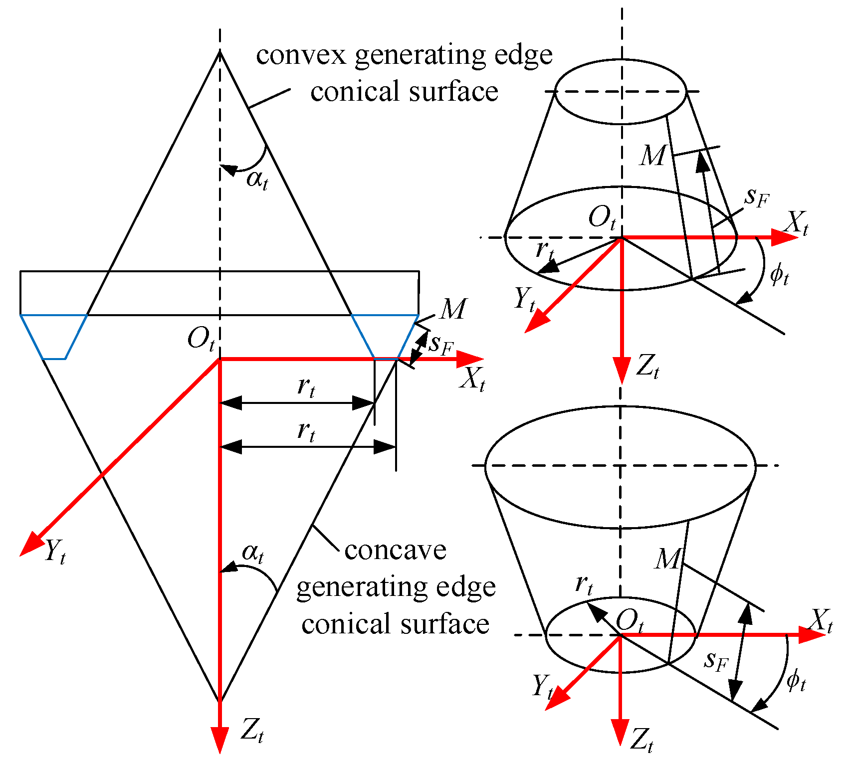
| Cutter Radius/mm | 114.3 | 114.8783 | 113.2378 | |
| Cutter Blade Angle/° | 22 | −18 | −22 | 18 |
| Radial Setting/mm | 98.2356 | 97.1595 | 99.1355 | |
| Angular Setting/mm | 72.3843 | 68.0297 | 75.7726 | |
| Ratio of Roll | 1.19825 | 1.79981 | 1.79903 | |
| Vertical Wheel Position/mm | 0 | −1.8673 | 1.859 | |
| Axial Wheel Position/mm | 0 | 1.2731 | −1.376 | |
| Sliding Base Setting/mm | 0 | −0.652 | 0.705 | |
| Blank Tilt Angle/° | 51.88 | 30.8039 | ||
| JD45+ | 650GMS | Difference (%) | Deviation Position | ||||||
|---|---|---|---|---|---|---|---|---|---|
| Convex | Concave | Convex | Concave | Convex | Concave | Convex | Concave | ||
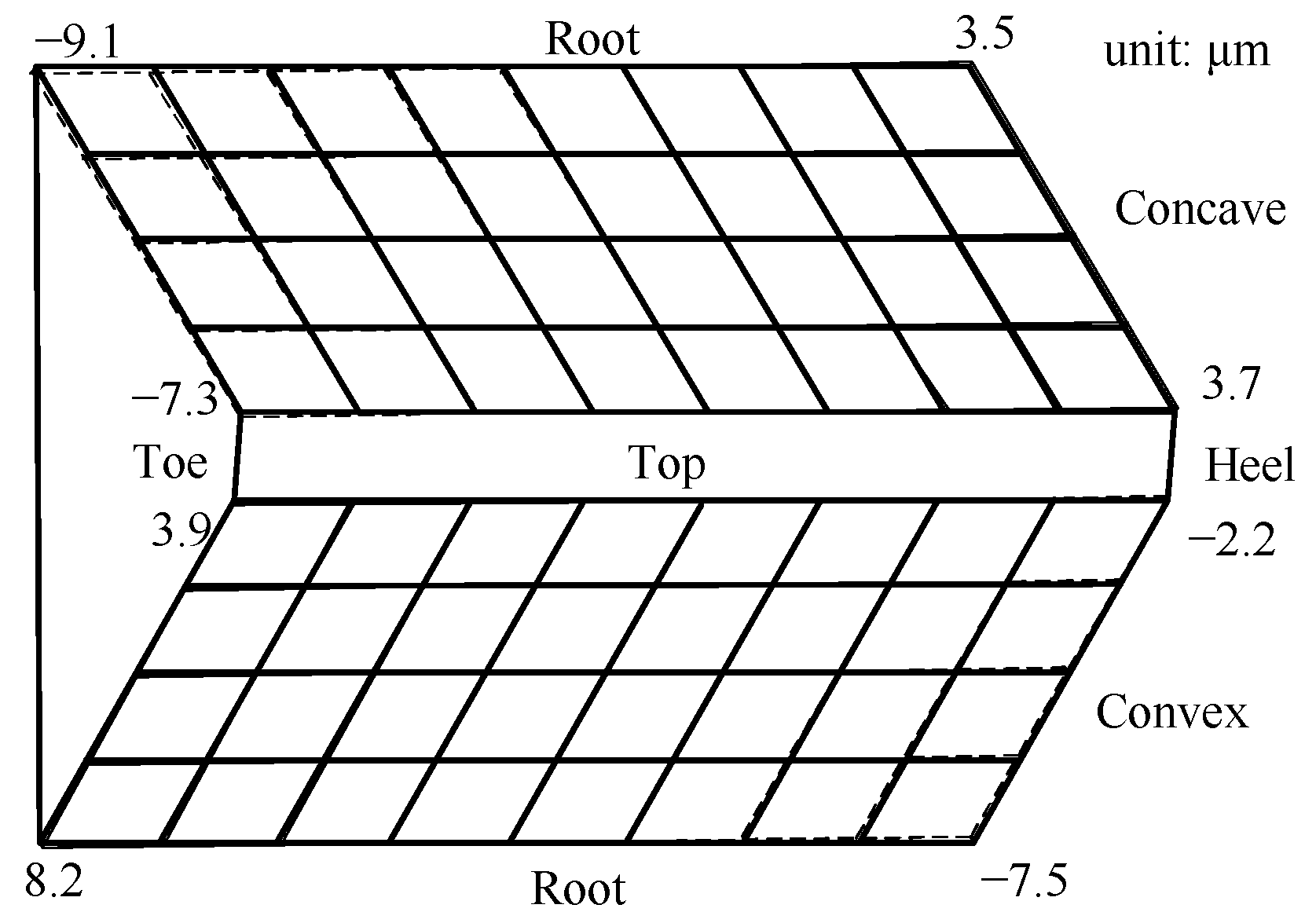
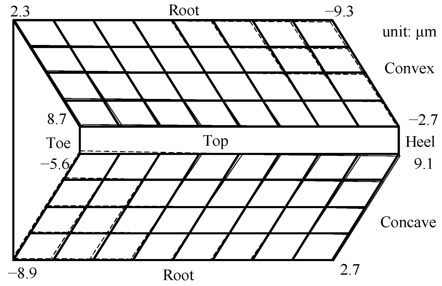
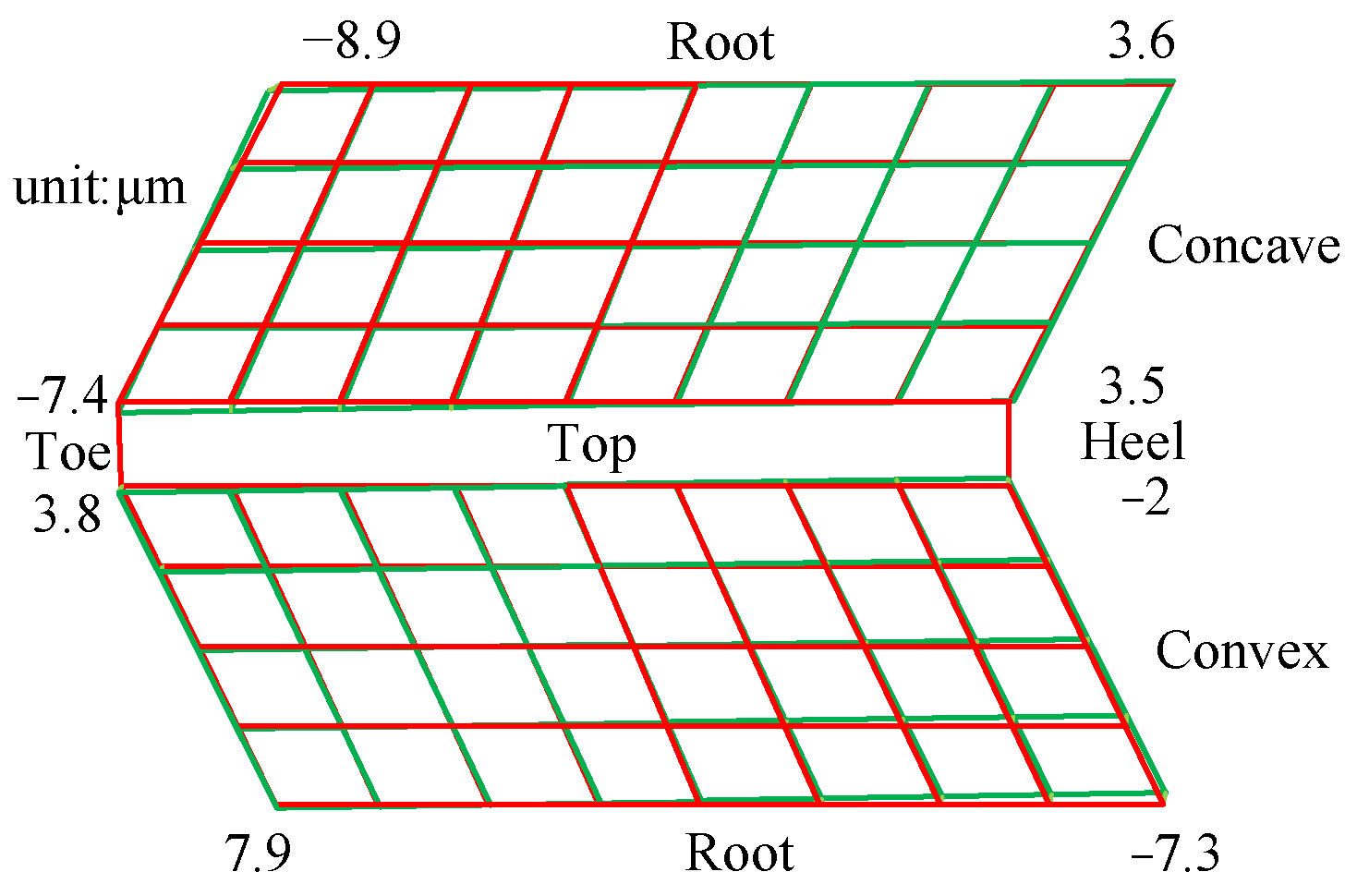
| Pinion | MPD | 3.9 | 3.5 | 3.8 | 3.6 | 2.6% | 2.9% | Top of toe | Root of heel |
| MND | −7.5 | −7.3 | −7.3 | −7.4 | 2.7% | 1.4% | Root of heel | Top of toe | |
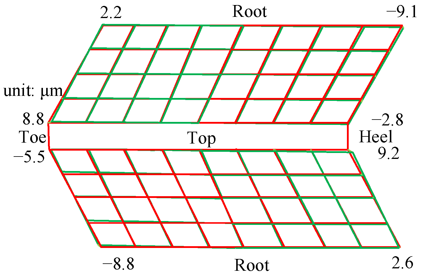
| Gear | MPD | 2.3 | 9.1 | 2.2 | 9.2 | 4.5% | 1.1% | Root of toe | Top of heel |
| MND | −2.7 | −8.9 | −2.8 | −8.8 | 3.7% | 1.1% | Top of heel | Root of toe | |
Disclaimer/Publisher’s Note: The statements, opinions and data contained in all publications are solely those of the individual author(s) and contributor(s) and not of MDPI and/or the editor(s). MDPI and/or the editor(s) disclaim responsibility for any injury to people or property resulting from any ideas, methods, instructions or products referred to in the content. |
© 2026 by the authors. Licensee MDPI, Basel, Switzerland. This article is an open access article distributed under the terms and conditions of the Creative Commons Attribution (CC BY) license.
Share and Cite
Deng, J.; Yang, H.; Li, T.; Jiang, C.; Li, S. A Method for Analyzing the Meshing Contact Performance of Real Tooth Surfaces of Spiral Bevel Gears. Lubricants 2026, 14, 138. https://doi.org/10.3390/lubricants14030138
Deng J, Yang H, Li T, Jiang C, Li S. A Method for Analyzing the Meshing Contact Performance of Real Tooth Surfaces of Spiral Bevel Gears. Lubricants. 2026; 14(3):138. https://doi.org/10.3390/lubricants14030138
Chicago/Turabian StyleDeng, Jing, Hao Yang, Tianxing Li, Chuang Jiang, and Shaoyang Li. 2026. "A Method for Analyzing the Meshing Contact Performance of Real Tooth Surfaces of Spiral Bevel Gears" Lubricants 14, no. 3: 138. https://doi.org/10.3390/lubricants14030138
APA StyleDeng, J., Yang, H., Li, T., Jiang, C., & Li, S. (2026). A Method for Analyzing the Meshing Contact Performance of Real Tooth Surfaces of Spiral Bevel Gears. Lubricants, 14(3), 138. https://doi.org/10.3390/lubricants14030138