Article

Research on the Lubrication Properties of Perfluoropolyether-Based Magnetic Fluid as a Space Bearing Candidate Lubricant


1
School of Mechanical and Electronic Control Engineering, Beijing Jiaotong University, Beijing 100044, China
2
State Key Laboratory of Tribology in Advanced Equipment, Tsinghua University, Beijing 100084, China
*
Author to whom correspondence should be addressed.
Lubricants 2026, 14(3), 131; https://doi.org/10.3390/lubricants14030131
Submission received: 29 December 2025 / Revised: 20 February 2026 / Accepted: 21 February 2026 / Published: 18 March 2026

Abstract

As a promising solution to lubrication failure in space environments where conventional oils suffer from splashing and leakage, magnetic fluids (MFs) offer significant potential. This study synthesized a perfluoropolyether (PFPE)-based MF tailored for space applications, demonstrating low-temperature fluidity at −40 °C, low saturated vapor pressure (3.37 Pa at 75 °C), and high stability (>6 months). To evaluate its lubrication effect, four magnetic thrust ball bearing structures were designed, with magnetic fields optimized via simulation. A magnetic field-controllable lubrication test bench was constructed accordingly. Comparative tests under varying friction conditions revealed that MF lubrication extended bearing service life. Specifically, the bearings lubricated with 7.5 wt.% MF exhibited the longest service life, which was doubled compared to the service life of the bearings lubricated with the carrier liquids. When compared to bearings without the application of a magnetic field, the service life of bearings lubricated with MFs of the same mass fraction increased by a factor of 3 to 4. This initial finding suggests the viability of using MFs in space lubrication applications.

1. Introduction

Magnetic fluid (MF), as a new type of liquid lubricant, is composed of carrier liquids, magnetic nanoparticles, and surfactants [1,2]. This nanomaterial can be controlled by external magnetic fields, being confined to specific lubrication areas to resist lubricant migration caused by microgravity, high temperature, and centrifugal force [3]. Magnetic field mediation induces shear-thickening behavior in MFs, wherein enhanced apparent viscosity facilitates optimized Hertzian contact stress redistribution [4]. With the exceeding exploration of deep space, the challenge of adapting various harsh space environments is intensifying, such as high temperature, low temperature, temperature cycling, vacuum, microgravity, high-energy particle radiation, etc. [5,6]. A large number of ball bearings used in spacecraft face a series of liquid lubrication failure problems that are different from those on the ground, such as volatilization, condensation, migration, and loss of weight [7]. MF lubrication can greatly compensate for the shortcomings of existing liquid lubrication, attracting wide interest.
MF lubrication is a process that employs MFs to replace or enhance conventional lubricants, with the aim of lubricating the surfaces of two contacting components. The application of a corresponding magnetic field has been demonstrated to enhance friction characteristics, reduce the coefficient of friction, minimize wear, and extend the service life of the contact components. The application of MF lubrication is pertinent to various components and mechanisms, including sliding bearings, gears, rolling bearings, and any complex moving mechanisms involving mutual surface contact [8]. The classification of MFs encompasses kerosene-based, water-based, and ester-based formulations. In comparison with conventional types, PFPE-based fluids demonstrate a higher degree of suitability for utilization as space lubricants. Their exceptional properties—including a wide temperature range and low saturated vapor pressure—render them particularly well suited for the extreme conditions of space, such as extreme temperatures, high vacuum, and microgravity environments.
Li et al. [9,10] conducted research on the factors that influence the stability of colloids in different MF carrier liquids and developed PAO-based MF, which is a promising candidate for magnetic lubrication applications. Kinjal Trivedi et al. [11] found that the addition of magnetic nanoparticles to low-viscosity mineral oil can enhance both anti-friction and anti-wear properties. According to Huang et al. [12,13], incorporating Fe3O4 nanoparticles into MFs leads to a remarkable enhancement in their tribological properties. Using a numerical framework combining the modified Reynolds equation with finite difference discretization, Liang et al. [14,15] determined that wall slip effects and fluid inertia contribute 15.98% and 2.33%, respectively, to friction enhancement in laminar flow regimes. The application of a magnetic field induces the self-assembly of magnetic particles into aligned chains within the carrier liquids, leading to a notable increase in oil film thickness and a simultaneous improvement in bearing load capacity and lubricant efficiency [16]. Jones [17] studied the application of perfluoropolyether (PFPE) in aerospace lubrication and pointed out that it has good thermal stability, chemical stability, viscosity–temperature characteristics, and low volatility in vacuum. Therefore, this paper selects PFPE as the carrier liquid for MF.
The unique properties of MFs have been leveraged by researchers to design innovative bearing structures that utilize MF lubrication. Xu et al. [18] embedded permanent magnets in the orbit of thrust ball bearings to attract MF lubricants, reducing the loss of lubricants during the bearing operation process, delaying the arrival of the dry oil state, and effectively improving the bearing’s service life. Li et al.’s [19] preliminary exploration has shown that MFs exhibit good support and lubrication properties within an array of permanent magnet rings. Wang et al. [20] introduced a bearing model combining the standard structure with magneto-fluidic lubrication, revealing magnetic flux density in the rolling element contact area under applied magnetic fields. Shen et al. [21] developed MF lubrication with magnetic surface texture, which can enhance low-velocity lubrication effectiveness when lubricated by MFs.
Viscosity is a pivotal indicator influencing the load-bearing capacity of lubricating oil films. It has been demonstrated that higher viscosity is associated with greater load-bearing capacity and increased starting torque. Conversely, lower viscosity is associated with reduced load-bearing capacity and diminished starting torque. Temperature and pressure have been shown to have a significant effect on viscosity, with changes in these parameters having a corresponding effect on the performance of the lubricating oil [22].
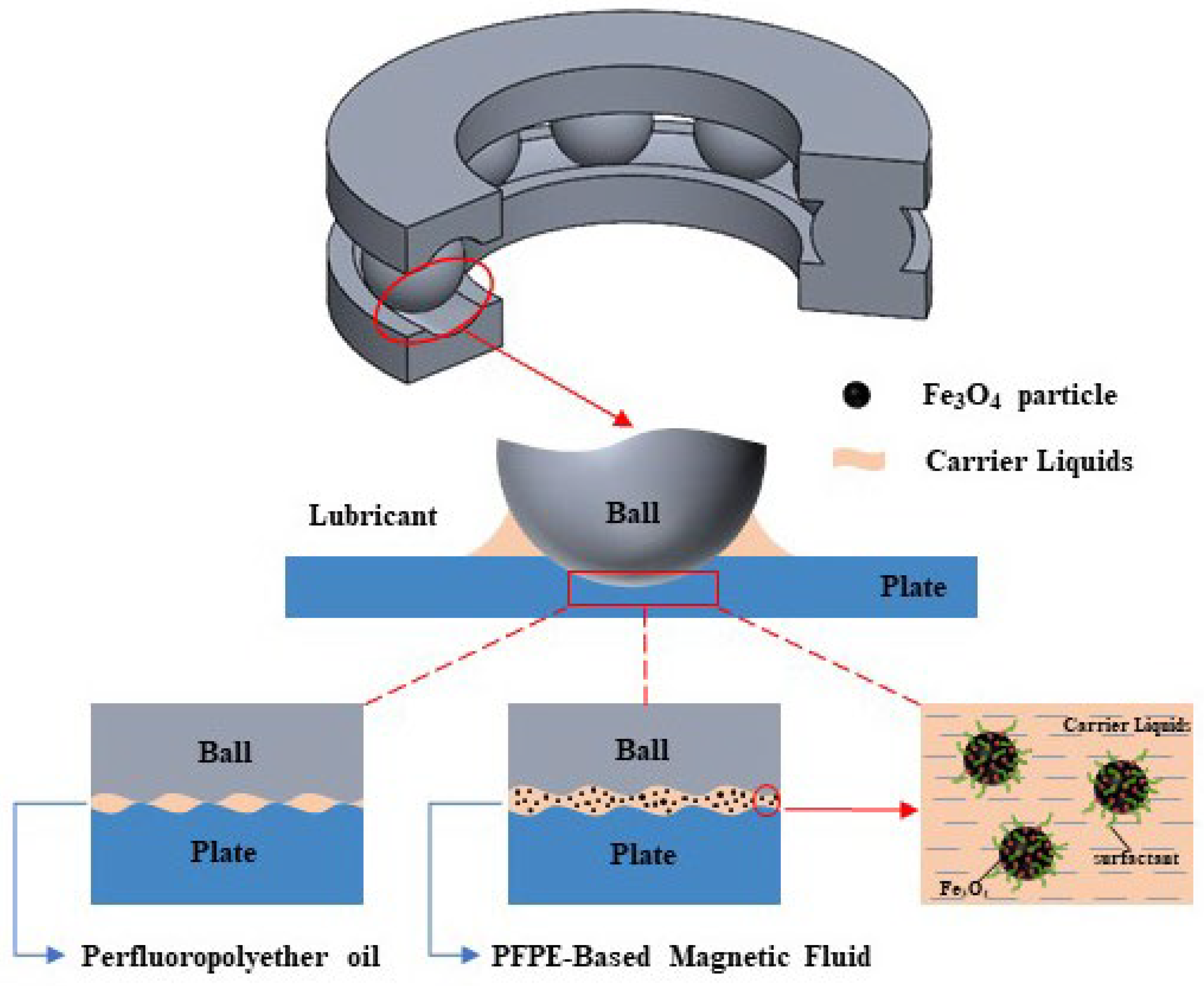
In this study, the relationship between the viscosity–temperature characteristics of lubricating oil and the lubrication effect is studied under the given experimental pressure conditions. We prepared MF lubricant with different mass fractions of PFPE through our previous methods as the subsequent experimental materials [23,24,25]. With thrust ball bearings as the lubrication target, according to the lubrication principle of MF lubrication, as shown in Figure 1, the magnetic circuit was designed to evaluate the lubrication performance of MF under the influence of a magnetic field. The bearing lubrication test bench was constructed to observe the torque and temperature of the carrier liquids and MF lubrication under a 240 mT magnetic field and under no magnetic field, respectively. The results indicated that it is possible to use MF lubrication as a candidate lubricant for space ball bearings with longer service life.

2. Materials and Methods

2.1. Preparation and Characterization of PFPE-Based MF

To investigate the tribological performance of PFPE-based MF lubricant, the synthesis process was conducted through the following steps: Initially, an aqueous solution containing Fe3+ and Fe2+ ions with a molar ratio of 1.7:1 was prepared. The solution (200 mL) was subsequently transferred to a thermostatic water bath maintained at 40 °C with continuous stirring at 400 rpm. Upon complete dissolution of the iron species, an excess of ammonia solution was gradually introduced to initiate precipitation. After 30 min of reaction, the resulting suspension underwent multiple washing cycles with deionized water until neutral pH (7.0 ± 0.2) was achieved.
The washed precipitate was then redispersed in 600 mL deionized water and subjected to hydrothermal treatment at 80 °C with stirring (400 rpm). During this stage, PFPE–carboxylic acid surfactant was added dropwise under alkaline conditions, allowing the reaction to proceed for 2 h. The residual water was removed by magnetic separation followed by drying in a vacuum oven (Beijing ZTE Instrument Co., Ltd., Beijing, China). The mass ratio of dispersant (Fe3O4 to PFPE) was maintained at 3:5. The synthesized PFPE-based MF was ultrasonically homogenized for 60 min using ultrasound to achieve a stable 37.5 wt.% MF. MF formulations (22.5 wt.% and 7.5 wt.%) were engineered via gravimetric blending at PFPE:carrier weight proportions of 3:2 and 1:4, respectively.
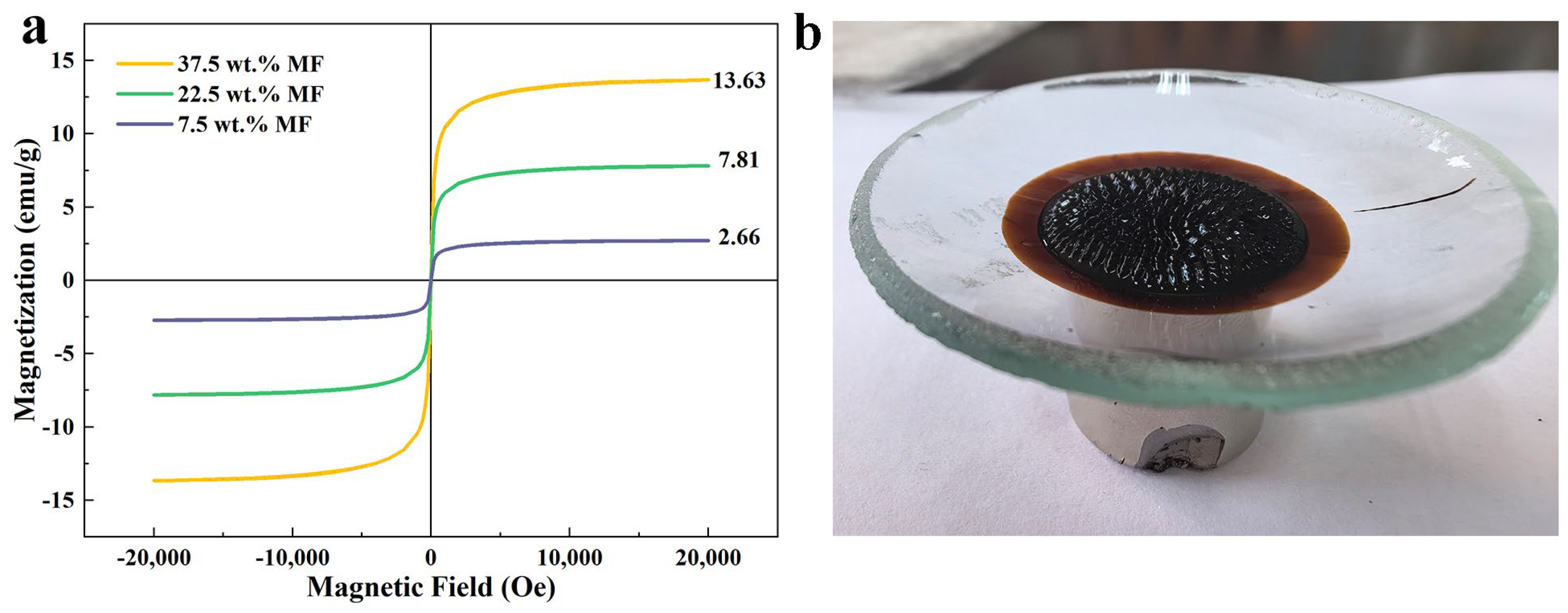
The magnetic properties of the PFPE-based MF were characterized using a vibrating sample magnetometer (VSM, Model 7400 series, Lake Shore Cryotronics, Columbus, OH, USA) under ambient conditions (20 ± 0.5 °C). As shown in Figure 2a, the magnetization curve revealed distinct superparamagnetic behavior with zero coercivity and negligible remanence. Quantitative analysis demonstrated that the 37.5 wt.% MF formulation achieved saturation magnetization (Ms) of 13.63 emu/g at an applied field intensity of 200 kA/m, with the magnetization intensity showing linear dependence on magnetic field strength below this critical threshold.
The colloidal stability of the PFPE-based MF was evaluated through stability characterization. As demonstrated in Figure 2b, the Rosensweig instability pattern remained intact after 6 months of static storage under magnetic confinement (NdFeB magnet, 0.5 T), confirming exceptional long-term stability.
The thermal stability of the 22.5 wt.% MF was quantitatively assessed through controlled evaporation testing. Triplicate measurements revealed an average mass loss of 2.64%. Rheological characterization via rotational viscometry (ASTM D445) confirmed preserved Newtonian flow behavior at cryogenic conditions, with the MF maintaining dynamic viscosity at −40 °C.
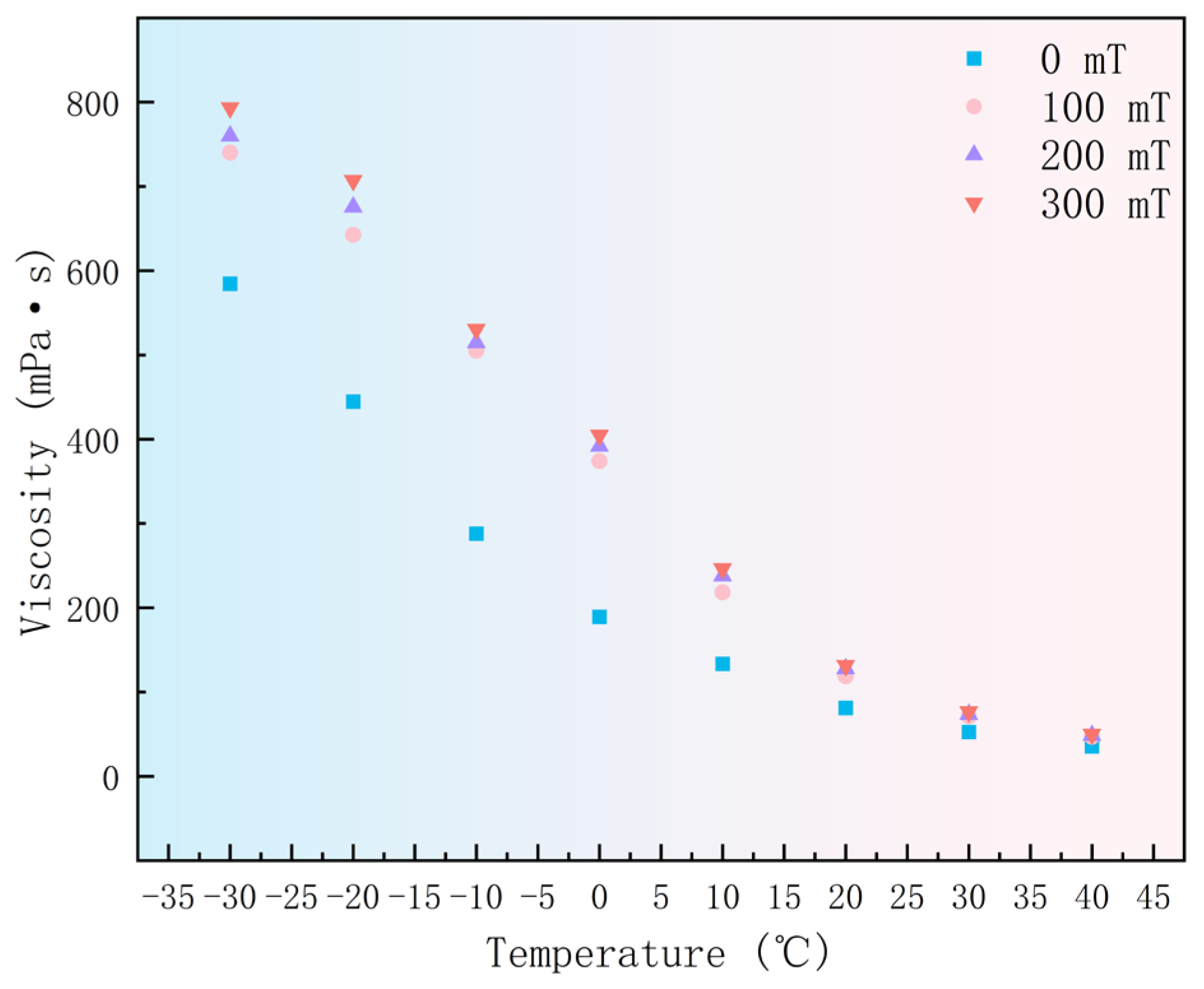
For MF, its viscosity is affected by the concentration of magnetic nanoparticles, temperature, and magnetic field. The higher the concentration of magnetic nanoparticles, the greater the viscosity. Therefore, we select 7.5 wt.% MF to characterize the viscosity–temperature under different magnetic fields.

2.2. Magnetic Circuit Design

In order to explore the rolling lubrication life and performance of MF, this paper selected thrust ball bearing, with circular NdFeB permanent magnet as magnetic source.
In 2021, Li et al. [19] utilized a bearing magnetic circuit comprising a small discrete cylindrical permanent magnet as a magnetic source to undertake a preliminary exploration of MF support and the lubrication characteristics of a permanent magnet ring array. However, it was observed that the magnetic field generated by this magnetic circuit has a maximum value at the raceway corresponding to the magnet. In the case of a bearing ball composed of magnetic material with a high permeability, it will be attracted to the location where the magnetic field intensity is greatest. When the bearing undergoes rotation, the ball must overcome the magnetic field force, which engenders substantial fluctuations in the load. Additionally, MF cannot be confined to the friction contact at all rotation angles, necessitating the design of a bearing magnetic circuit with a continuous magnetic source. In consideration of the factors of assembly and magnetic flux, the selected bearing is a standard NSK-51104 thrust ball bearing with an outer ring diameter of 35 mm and an inner ring diameter of 20 mm. The inner and outer diameters of the permanent magnet are consistent with the bearing, with a height of 10 mm. Four designs were conceived, as illustrated in Figure 3.

2.3. Analysis of Magnetic Circuit Simulation

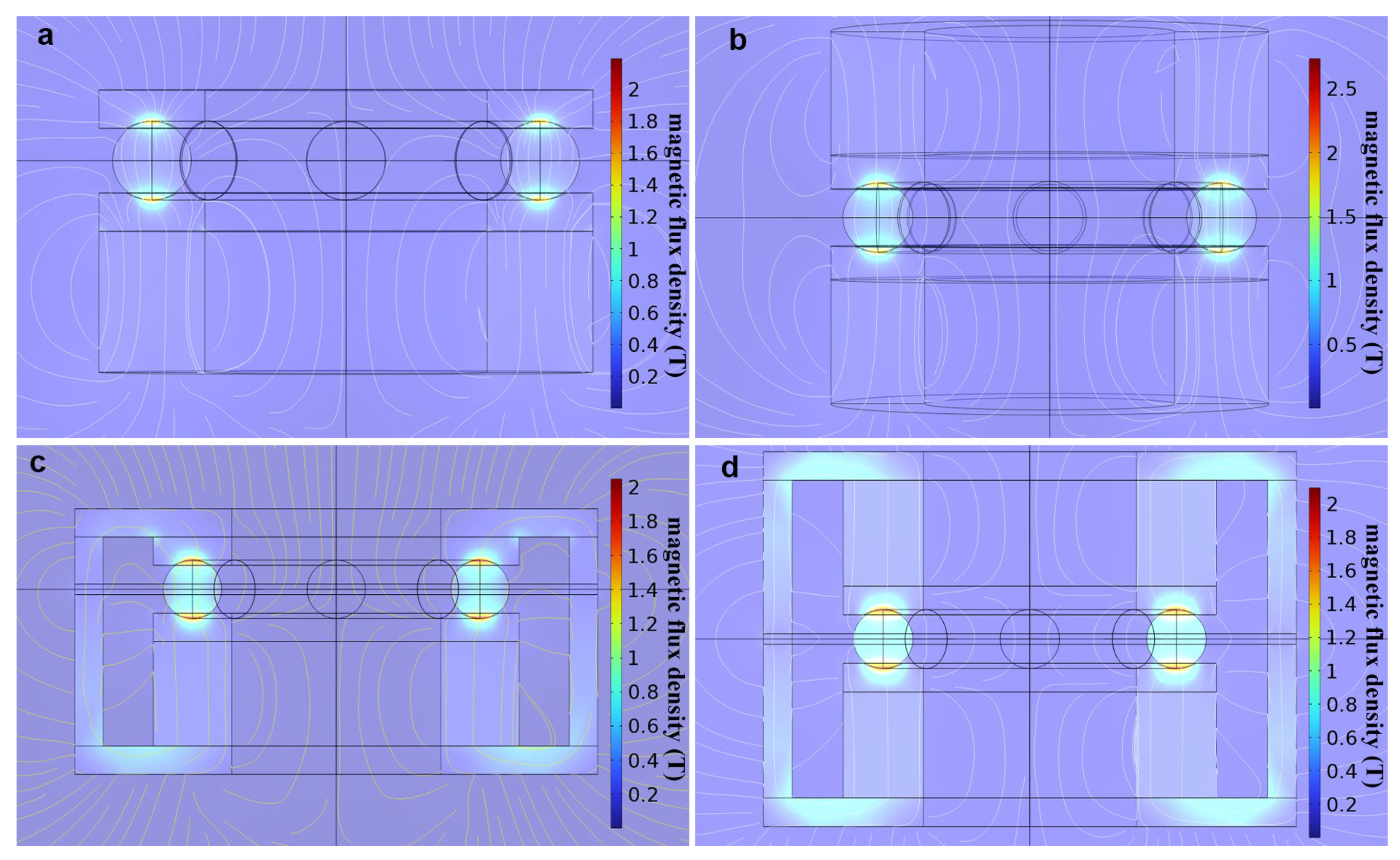
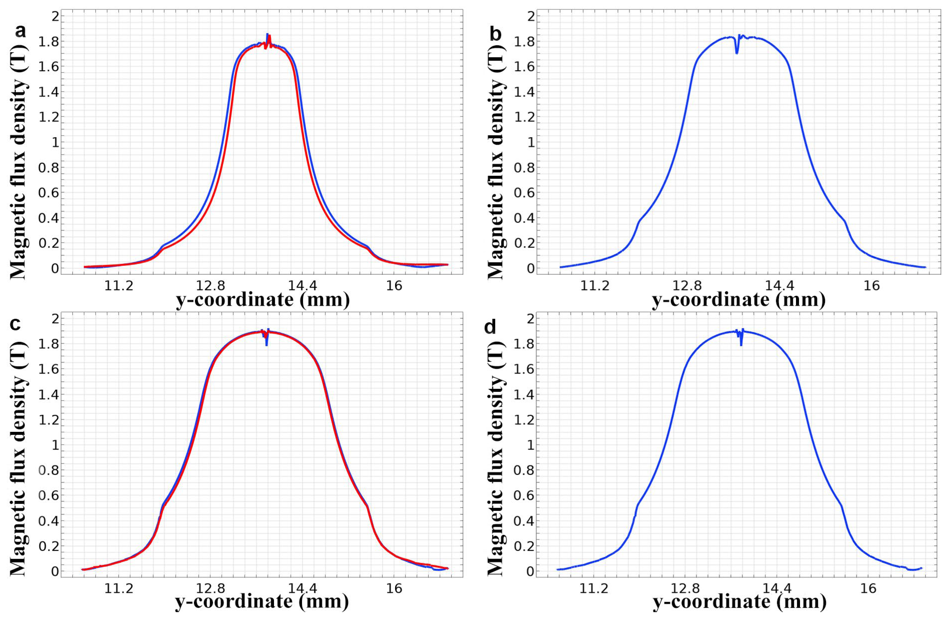
In this study, the gap between the upper and lower magnetic shields is set at 0.1 mm. Figure 4 shows the axial flux density distribution patterns for different magnetic circuit designs in the bearing under this condition. The figure shows that all four designs can form high-flux-density regions at the gap between the rolling elements and the raceways. The corresponding magnetic flux density contour lines are shown in Figure 5. Among them, the single-sided permanent magnet exhibits geometric asymmetry, with blue color indicating the side closer to the permanent magnet and red color representing the side farther away from the permanent magnet. In unshielded single-pole magnet configurations, the magnetic flux density decays exponentially with increasing distance from the pole face. However, for the single-sided permanent magnet with a magnetic shield design, the magnetic flux density contour lines at the upper and lower locations overlap almost completely. It indicates that the magnetic circuit with a magnetic shield has less magnetic leakage. A comparison of the magnetic flux density modulus extremes reveals that with the exception of the narrower region corresponding to the extreme in Figure 4a, the other three show no significant difference. Consequently, further quantitative comparison is required.
The magnetic flux density distribution along the parameterized curve and parameterized surface paths in proximity to the permanent magnet was integrated for each model. Additionally, a model with a gap size of 1 mm between the magnetic shields was included as a comparative analysis to investigate the impact of different gap sizes on the results. The outcomes of these investigations are presented in Table 1, providing a comprehensive understanding of the influence of gap size between the magnetic shields.
The smaller the gap between the magnetic shields, the greater the increase in magnetic flux density. Theoretically, this can be attributed to the reduction of magnetic leakage by the magnetic shields. With a smaller gap between the magnetic shields, the magnetic leakage is further minimized, allowing more magnetic field lines to pass through the narrow gap between the rolling elements and the raceways.
The volume and weight constraints on spacecraft devices are highly stringent. Therefore, further analysis of device volume and weight should be considered. The density of neodymium–iron–boron (NdFeB) materials ranges from 7.5 to 7.7 g/cm3, while the density of commonly used magnetic shielding materials ranges from 7.70 to 7.86 g/cm3, showing minimal differences. Thus, the focus should be on the additional volume introduced by the magnetic circuit design. Since surface integration is more representative in practical applications, the ratio of the relative increase in surface integration to the relative increase in volume is evaluated to measure the increase in surface integration resulting from the increased volume. This ratio is referred to as the volume efficiency. By calculation, among all the designs, we find that the magnetic circuit design with a double-sided permanent magnet and no magnetic shields exhibits the highest volume efficiency, reaching 80.98%. Additionally, it provides a sufficiently large surface integration of magnetic flux density, which is beneficial for localized lubrication with magnetic fluids. Therefore, the final design choice was to adopt a magnetic circuit configuration with a two-sided permanent magnet without a magnetic shield.

2.4. Experiment Platform Construction and Experiment Scheme Design

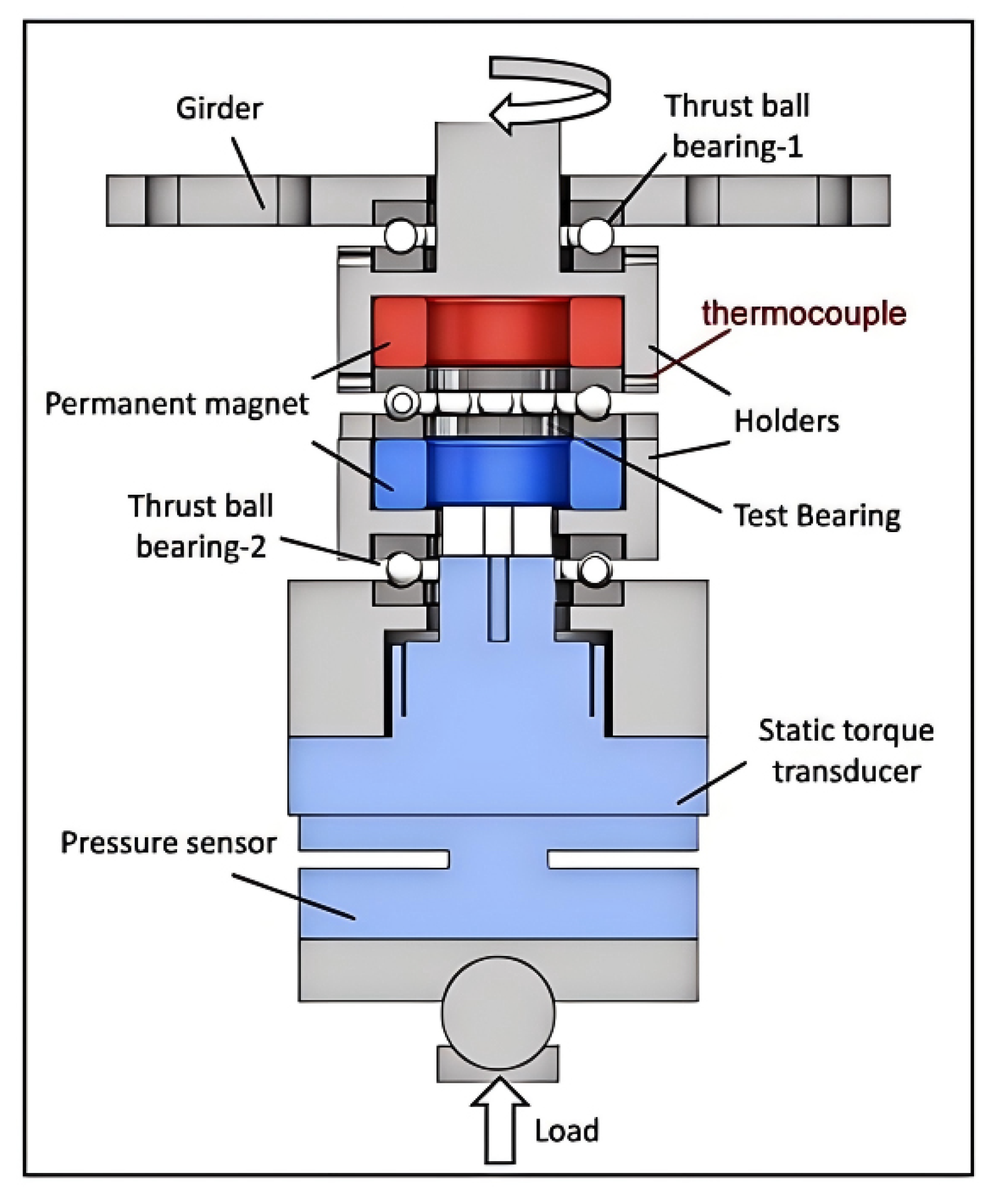
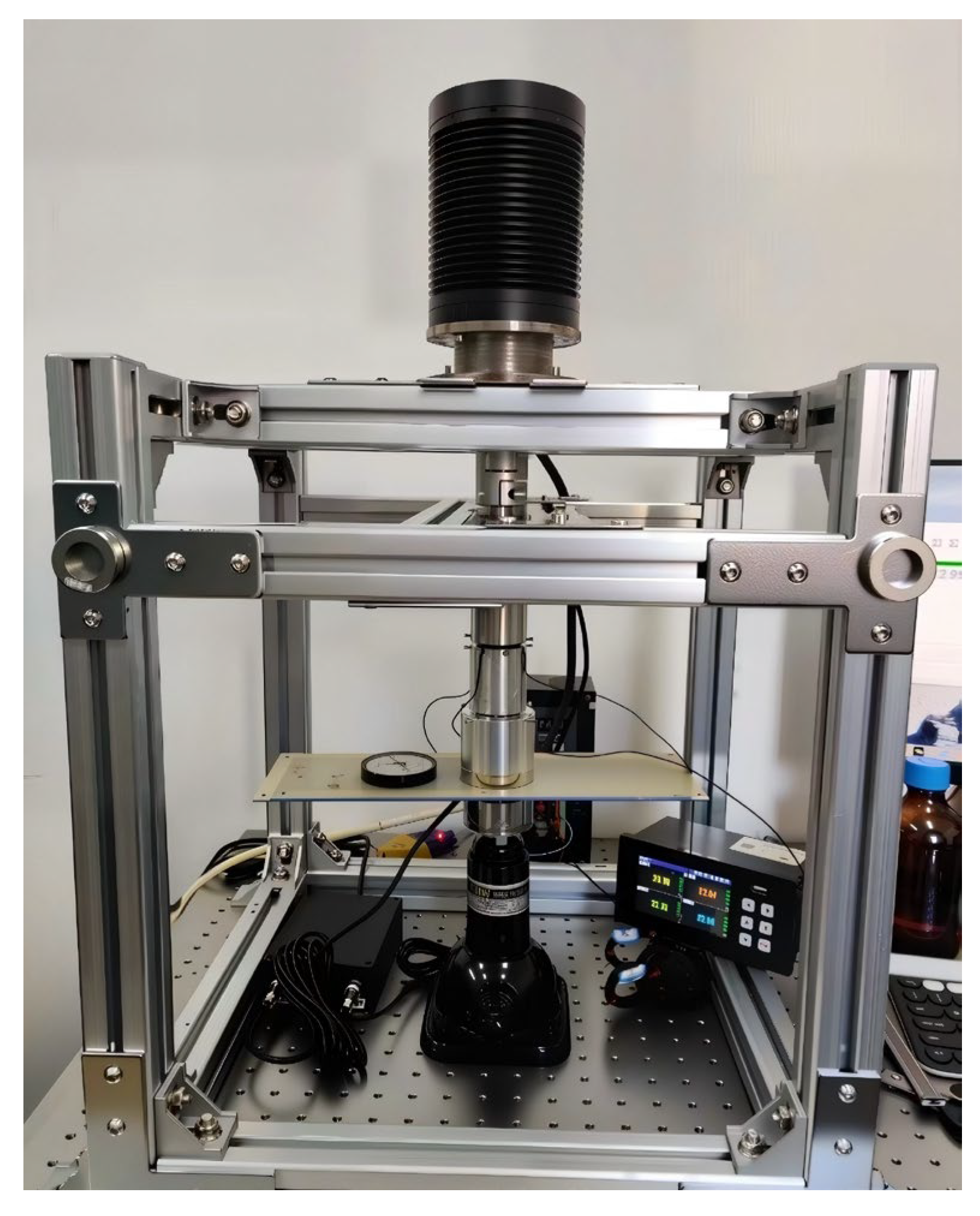
As shown in Figure 6, a test bench was constructed based on the magnetic circuit design for thrust ball bearings. Permanent magnets were fixed on both sides of the test thrust ball bearing to generate a magnetic field at the bearing raceway. The motor drove the test bearing to rotate, transmitting static torque from the seat ring to the static torque sensor, which was used to evaluate the lubrication performance of the bearing.
Based on experimental observations indicating severe bearing damage and accelerated degradation beyond a static torque threshold of 0.3 N·m, coupled with the risk of demagnetization in permanent magnets and diminished MF performance at temperatures exceeding 120 °C, these specific values were established as definitive termination criteria to consistently mark functional failure. This operational endpoint intentionally represents a practical engineering limit rather than the onset of wear, acknowledging that wear initiation occurred earlier but ensuring test comparability by defining failure through measurable, repeatable functional impairment thresholds. The selection of 0.3 N·m directly correlates with observed abrupt performance deterioration, while the 120 °C limit safeguards against irreversible material degradation, collectively addressing both mechanical and thermal failure modes critical to bearing functionality and magnetic component integrity. We explicitly clarify that this criterion captures functional endpoint reliability and acknowledge the inherent variability in wear initiation timing relative to this threshold in the manuscript.
As shown in Figure 7, according to the purpose of the experiment, the factors considered include the magnetic field condition and the type of lubricant. Based on the experimental design, the constructed bearing lubrication test bench was used to conduct bearing lubrication tests under eight different operating conditions, and each experimental group was repeated three times to ensure data accuracy, as shown in Table 2.

3. Results and Discussion

3.1. Thermal Stability Performance Analysis

In comparison with conventional MF lubricants, the PFPE-based MF developed in this study demonstrates superior viscosity–temperature characteristics, as shown in Figure 8. The material displays minimal variation in viscosity when subjected to changes in temperature. In contrast, the three magnetic fluid lubricants listed in Zhang’s [26] paper have been shown to demonstrate a viscosity reduction from 700 mPa·s to 100 mPa·s between 25 °C and 40 °C. By contrast, the viscosity of the PFPE-based MF decreased only from 100 mPa·s to 30 mPa·s, thus demonstrating superior viscosity–temperature behavior. This study further characterized the MF’s viscosity–temperature performance at low temperatures. The findings suggest that PFPE-based MF displays excellent viscosity–temperature properties over a wide temperature range, making it more appropriate for aerospace applications. In friction experiments employing this MF, its unique rheological properties under magnetic field conditions influence its fundamental friction characteristics, specifically affecting the initial static torque value when the experiment stabilizes. However, this value exerts minimal influence on the lubrication effectiveness or service life of the bearing. Conversely, the enhanced static torque contributes to the prolongation of the bearing’s operational lifespan.

3.2. Friction Performance Analysis

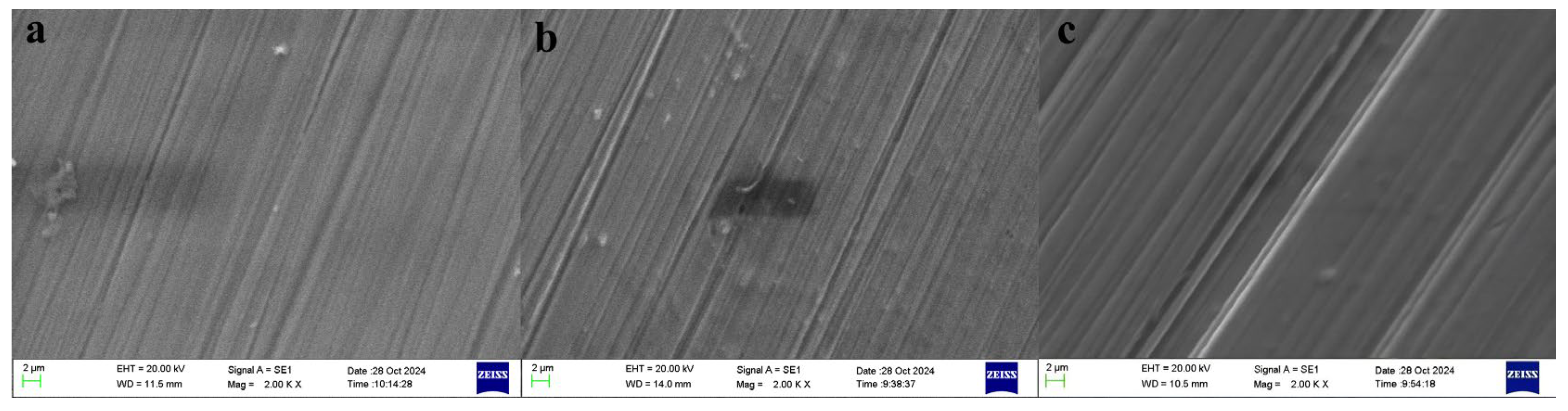
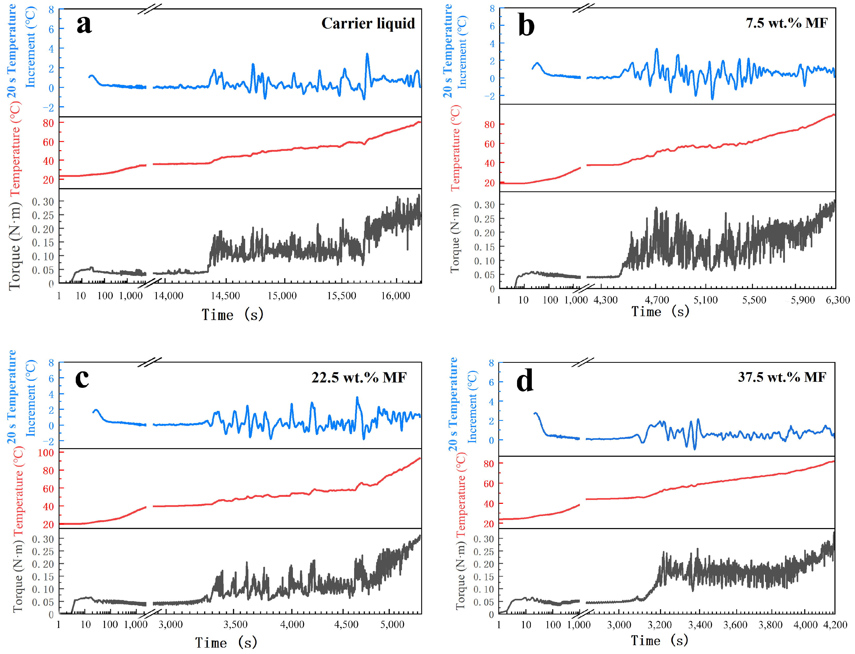
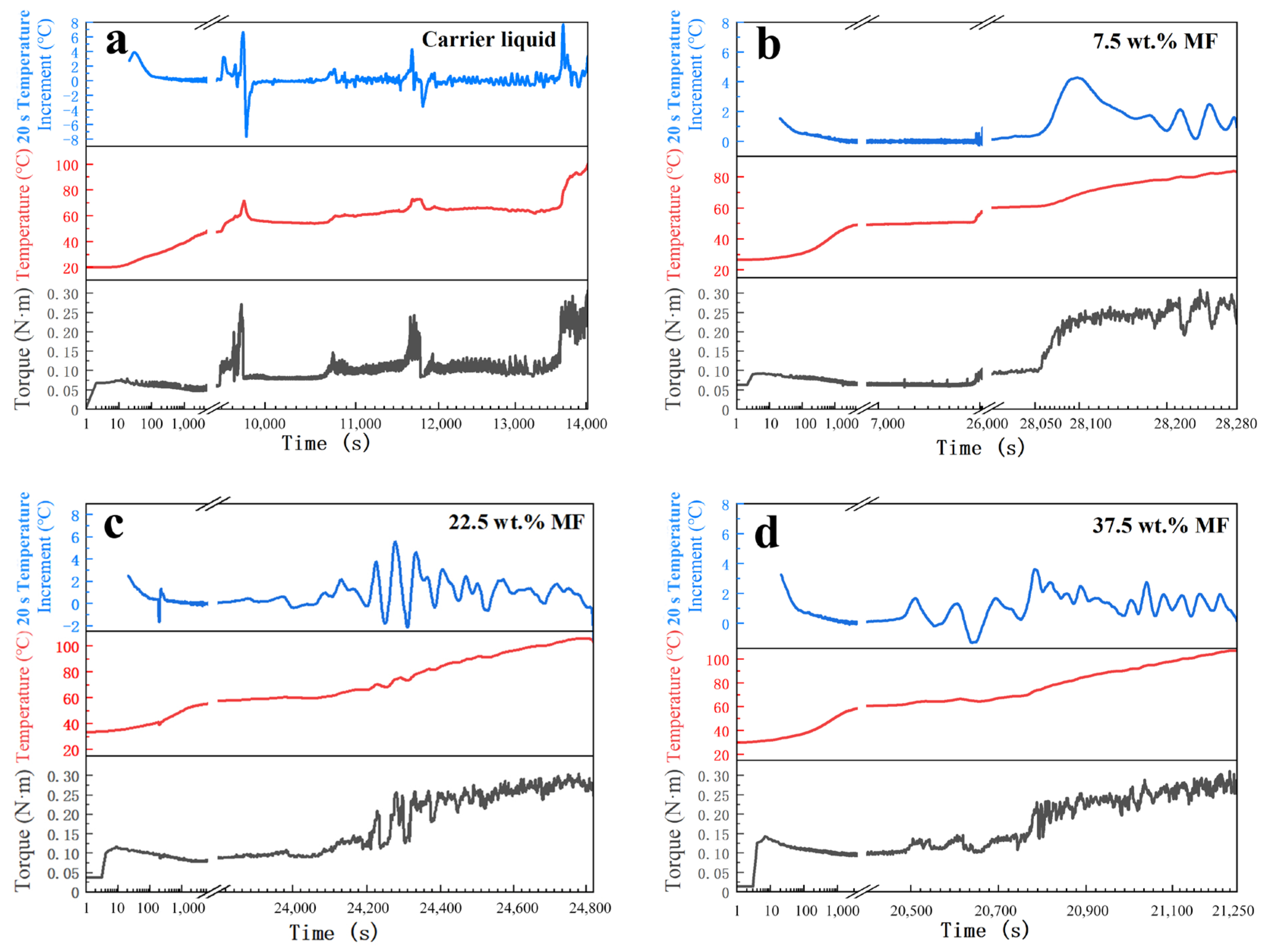
We repeated the bearing lubrication tests under all eight working conditions in Table 2 to ensure stable test life and lubrication performance. Scanning electron microscopy (SEM, EVO18) analysis of the bearing substrate revealed wear-induced surface features in Figure 9. Lower magnetic fluid (MF) concentrations resulted in reduced surface abrasion marks and smoother surfaces. Figure 10 and Figure 11 present experimental datasets where black, red, and blue curves, respectively, represent static torque, temperature rise, and temperature dynamics over 20 s intervals. Since torque variations primarily occur during initial and final operational stages, we set measurement breakpoints during stable intermediate periods. This approach facilitates observation of torque, temperature, and temperature rise changes at operation starting/endpoints.
Figure 10 and Figure 11 show good agreement between the torque and temperature rise curves. In this operating condition, heat transfer occurs primarily through conduction and convection. The temperature difference acts as the driving force for this heat transfer. When friction in the bearing increases or decreases, it disrupts the balance between heat generation and dissipation. This disruption causes the temperature at the thermocouple to increase or decrease. The change corresponds to a positive or negative temperature rise. Heat transfer requires time. Therefore, both the temperature rise curve and the temperature curve lag slightly behind the static torque curve.
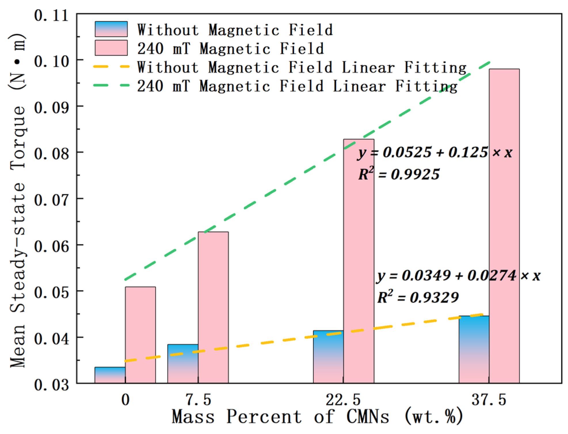
Figure 12 displays the linearly fitted average steady-state torque curve. The fitting formula without a magnetic field is y = 0.0349 + 0.0274 x , R2 = 0.9329. The fitting formula for a 240 mT magnetic field is y = 0.0525 + 0.125 x , R2 = 0.9925. The slope of the fitting formula under the magnetic field is about 4.56 times that without the magnetic field, indicating that under the experimental conditions, the addition of 7.5 wt.% and above Fe3O4 nanoparticles will increase the friction coefficient, and the average steady-state torque is positively correlated with the Fe3O4 nanoparticle content.
Comparing the average steady-state torque results reveals higher static torque under magnetic field influence. Three possible reasons may explain this phenomenon: (1) The non-uniformity of the permanent magnet and the bearing material results in an uneven magnetic field formed at the bearing raceway. Therefore, the rolling elements need to overcome a certain magnetic field binding force while rolling on the raceway. (2) The design of the magnetic circuit for lubricating the magnetic fluid involves two opposing permanent magnets clamping the thrust ball bearing, which leads to an increase in local load. Even under the same friction coefficient, the increase in local load causes an increase in the static torque of the bearing seat ring. (3) This phenomenon likely stems from field-induced chain alignment of surface-functionalized Fe3O4 nanoparticles, which further increases the resistance to bearing rotation [16].
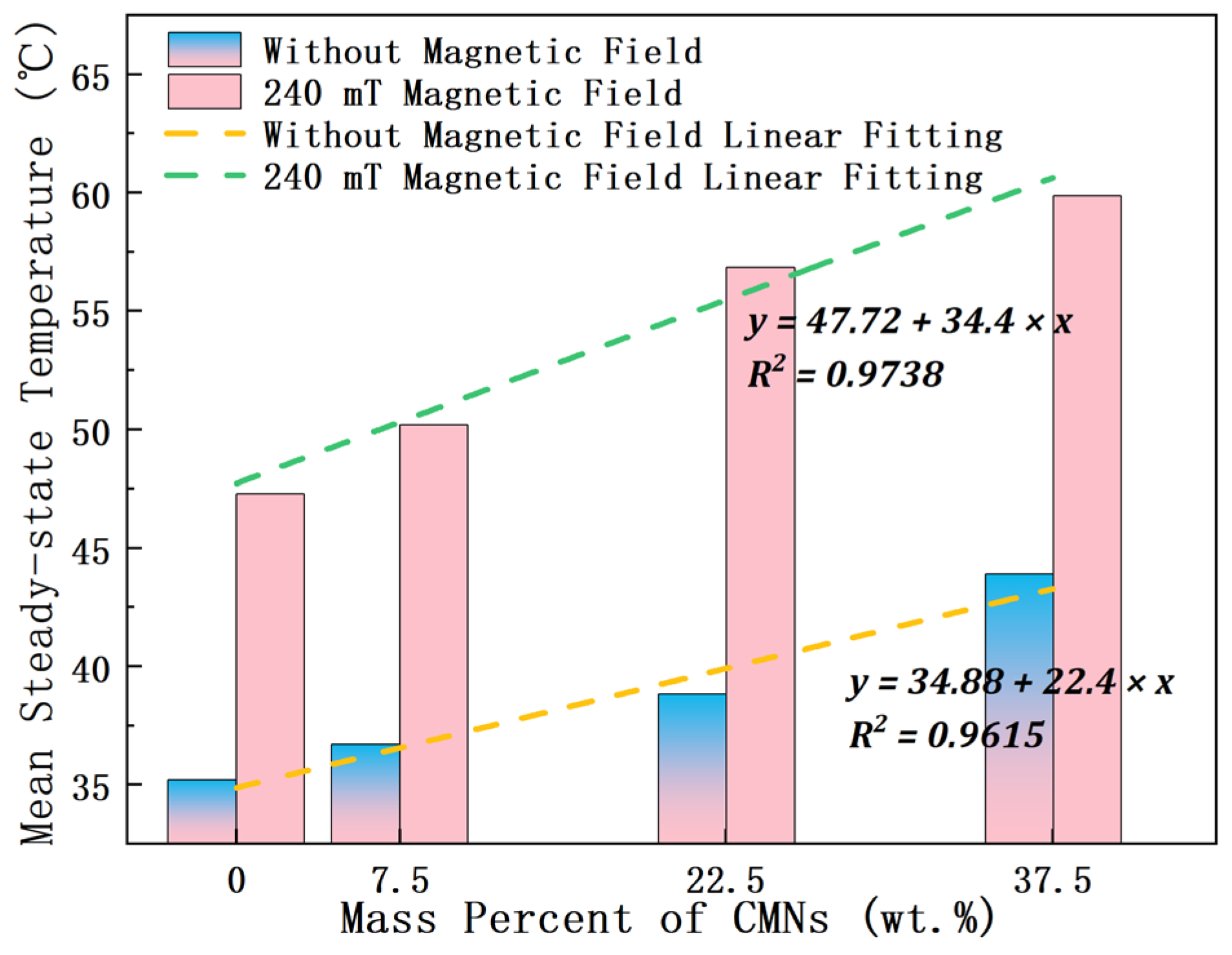
Figure 13 show that regardless of experimenting with or without magnetic field, the average steady-state temperature of the bearings increases with an increase in the content of Fe3O4 nanoparticles, which corresponds to the average steady-state torque. The fitted equation under no magnetic field is y = 34.88 + 22.4 x , R2 = 0.9615; under the influence of a magnetic field of 240 mT, the fitted equation is y = 47.72 + 34.4 x , R2 = 0.9738. The slope of the magnetic field fitted equation is approximately 1.54 times that of the non-field equation. However, this ratio is significantly smaller than the 4.56-fold difference observed in average steady-state torque. This discrepancy occurs because an increased temperature difference enhances heat dissipation nonlinearly. As the temperature difference grows, the heat dissipation effect becomes more pronounced.
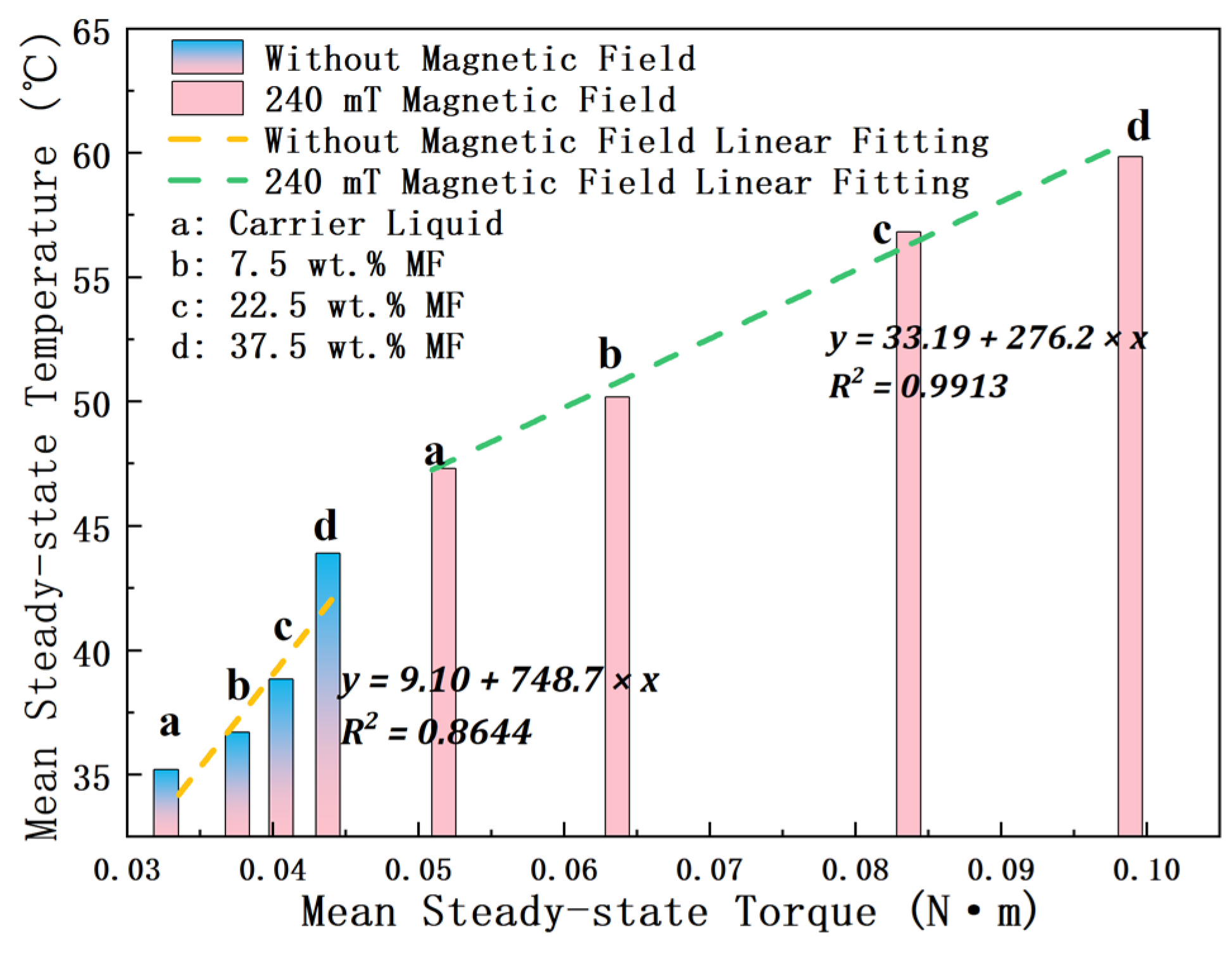
Figure 14 systematically quantifies the steady-state torque–temperature correlation in bearing assemblies. Under the influence of a magnetic field, a good linear fit is observed with the fitted equation for both variables as y = 33.19 + 276.2 x , R2 = 0.9913. However, in the absence of a magnetic field, the fitted equation for both variables is y = 9.10 + 748.7 x , R2 = 0.8644. Comparative analysis of the linear regression slopes reveals a 2.71-fold enhancement in the torque–temperature gradient under non-magnetized versus magnetized operational regimes. As mentioned earlier, this is due to the higher temperature difference leading to increased heat dissipation.
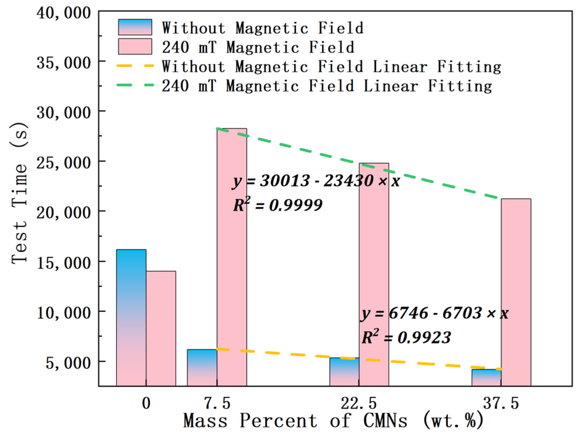
Figure 15 analyzes the bearing lifespan under different operating conditions. Without a magnetic field, carrier liquid lubrication achieves a 16,190 s lifespan. Under magnetic field influence, this value decreases to 14,024 s, representing a 13.38% reduction. Magnetic field actuation concurrently increases steady-state torque and temperature, exacerbating frictional energy dissipation and wear rates and consequently shortening bearing lifespan. With 7.5 wt.% Fe3O4 nanoparticles added, the lifespan decreases by 61.75% compared to pure carrier liquids. However, higher Fe3O4 nanoparticle concentrations progressively diminish the lifespan reduction rate. The post-addition lifespan data exhibits a strong linear relationship.
Observing the linear relationship between the bearing lifespan under a 240 mT magnetic field and the mass fraction of magnetic particles, the fitted equation is y = 30013 23430 x , with an R2 = 0.9999. Comparing the bearing lifespan under a 240 mT magnetic field with base oil lubrication to the lifespan of bearings lubricated with 7.5 wt.% magnetic fluid, there is a 101.35% increase in lifespan. Comparing the bearing lifespan with different lubricating oils under no magnetic field, under a 240 mT magnetic field, the lifespan of bearings lubricated with 7.5 wt.%, 22.5 wt.%, and 37.5 wt.% MF increases by 355.97%, 363.94%, and 407.15% respectively.
The experimental findings reveal that Fe3O4 nanoparticle incorporation into non-magnetized base oil deteriorates lubrication efficiency. However, under the influence of a magnetic field, Fe3O4 nanoparticles effectively constrain the base oil, reducing its loss under high-speed bearing rotation and ensuring sufficient lubrication in the friction zone. This reduction in wear increases the operational lifespan of the bearings.

4. Conclusions

This study introduces a novel space bearing candidate lubricant: PFPE-based MF. Through the bearing lubrication test, it was demonstrated that PFPE-based MF can extend bearing life and can be a space bearing candidate lubricant. The principal findings derived from this investigation are systematically categorized into three thematic domains:
(1) The successful preparation and characterization of different concentrations of PFPE-based MF: The results of this study show that PFPE-based MF exhibits superparamagnetic properties, low-temperature fluidity (at −40 °C), low saturated vapor pressure (3.37 Pa at 75 °C), and high stability (more than 6 months), thereby satisfying the criteria for its applicability within the space environment.
(2) We designed and simulated four magnetic circuits. After optimization, we constructed a thrust ball bearing lubrication test bench capable of applying magnetic fields. Based on simulation results for the line and surface integral of magnetic flux density, combined with magnetic circuit volume efficiency calculations, the two-sided permanent magnet design without magnetic shields was selected. The magnetic flux density line integral is 5.00 × 10⁻³ Wb/m, the surface integral is 8.08 × 10⁻⁶ Wb, and the volume efficiency is 80.98%. On this basis, a bearing lubrication test bench that can measure the static torque and temperature of the bearing seat ring was designed and built.
(3) Tribological evaluation of PFPE-based MF and carrier liquids was conducted on a bearing lubrication test platform under both non-magnetized (B = 0) and field-activated (B = 240 mT) conditions. Experimental results indicate that in the absence of magnetic fields, incorporating magnetic nanoparticles at mass fractions exceeding 7.5% elevates both the friction coefficient and volumetric wear. But under the 240 mT magnetic field, the life of MF-lubricated bearings is higher than that of carrier liquid-lubricated bearings. The life of the 7.5 wt.% MF-lubricated bearing is the longest, which is one time longer than that of carrier liquid-lubricated bearings. Compared with the bearing life without a magnetic field, the bearing life with the same mass fraction of MF lubrication under the magnetic field is increased by 3–4 times. However, it is critical to clarify that the defined “lifetime” here specifically refers to the time to reach the functional failure criteria (static torque ≥ 0.3 N·m or temperature ≥ 120 °C), not the onset of wear damage, which experimental evidence confirms occurred earlier with inherent variability in initiation timing across tests, though this variability did not materially alter the comparative efficacy conclusions between lubrication conditions. Based on the characterization of the MF and the lubrication test results, the feasibility of applying the prepared PFPE-based MF to space lubrication was demonstrated.

Author Contributions

Y.Z.: Methodology, Formal analysis, Conceptualization, Writing—original draft, and Writing—review, and editing. Z.Z.: Conceptualization, Methodology, and Supervision. J.J.: Methodology and Investigation. T.Z.: Methodology and Investigation. J.L.: Methodology and Investigation. D.L.: Conceptualization and Methodology. All authors have read and agreed to the published version of the manuscript.

Funding

This research was funded by the Fundamental Research Funds for the Central Universities (2025YJS145).

Data Availability Statement

The data presented in this study are available upon reasonable request.

Conflicts of Interest

The authors declare that they have no known competing financial interests or personal relationships that could have appeared to potentially influence the work reported in this paper.

References

  1. Rosensweig, R.E. Magnetic Fluids. Annu. Rev. Fluid. Mech. 1987, 19, 437–461. [Google Scholar] [CrossRef]
  2. Tadmor, R.; Rosensweig, R.E.; Frey, J.; Klein, J. Resolving the puzzle of ferrofluid dispersants. Langmuir 2000, 16, 9117–9120. [Google Scholar] [CrossRef]
  3. Uhlmann, E.; Spur, G.; Bayat, N.; Patzwald, R. Application of magnetic fluids in tribotechnical systems. J. Magn. Magn. Mater. 2002, 252, 336–340. [Google Scholar] [CrossRef]
  4. Rosensweig, R.E.; Kaiser, R.; Miskolczy, G. Viscosity of magnetic fluid in a magnetic field. J. Colloid. Interface Sci. 1969, 29, 680–686. [Google Scholar] [CrossRef]
  5. McKnight, D. Examination of spacecraft anomalies provides insight into complex space environment. Acta Astronaut. 2019, 158, 172–177. [Google Scholar] [CrossRef]
  6. Wu, J.-G.; Eliasson, L.; Lundstedt, H.; Hilgers, A.; Andersson, L.; Norberg, O. Space environment effects on geostationary spacecraft: Analysis and prediction. Adv. Space Res. 2000, 26, 31–36. [Google Scholar] [CrossRef]
  7. Nautiyal, H.; Singh, S.; Gautam, R.K.S.; Goswami, R.N.; Khatri, O.P.; Verma, P.; Tyagi, R. The state of art on lubrication methods in space environment. Phys. Scr. 2024, 99, 022003. [Google Scholar] [CrossRef]
  8. Ochoński, W. Sliding bearings lubricated with magnetic fluids. Ind. Lubr. Tribol. 2007, 59, 252–265. [Google Scholar] [CrossRef]
  9. Liu, L.; Decai, L.; Zhili, Z. Colloidal Stability of Magnetite Nanoparticles Coated by Oleic Acid and 3-(N,N-Dimethylmyristylammonio)propanesulfonate in Solvents. Front. Mater. 2022, 9, 893072. [Google Scholar] [CrossRef]
  10. Liu, L.; Decai, L.; Zhili, Z. Rheological and magnetic properties of stable poly alpha olefins based ferrofluids with high viscosity and magnetization. J. Magn. Magn. Mater. 2022, 564, 170096. [Google Scholar] [CrossRef]
  11. Trivedi, K.; Kothari, A.; Parekh, K.; Upadhyay, R.V. Effect of Particle Concentration on Lubricating Properties of Magnetic Fluid. J. Nanofluids 2018, 7, 420–427. [Google Scholar] [CrossRef]
  12. Huang, W.; Shen, C.; Liao, S.; Wang, X. Study on the Ferrofluid Lubrication with an External Magnetic Field. Tribol. Lett. 2011, 41, 145–151. [Google Scholar] [CrossRef]
  13. Huang, W.; Wang, X.; Ma, G.; Shen, C. Study on the Synthesis and Tribological Property of Fe3O4 Based Magnetic Fluids. Tribol. Lett. 2009, 33, 187–192. [Google Scholar] [CrossRef]
  14. Rongyu, W.; Hongjian, T.; Yunshan, F.; Jinan, Z.; Honglei, L.; Hui, H.; Shumei, C. Study on wall-slip effect of magnetorheological fluid and its influencing factors. J. Intell. Mater. Syst. Struct. 2022, 33, 352–364. [Google Scholar] [CrossRef]
  15. Xie, Z.-L.; Ta, N.; Rao, Z.-S. The lubrication performance of water lubricated bearing with consideration of wall slip and inertial force. J. Hydrodyn. Ser. B 2017, 29, 52–60. [Google Scholar] [CrossRef]
  16. Ivanov, A.O.; Zubarev, A. Chain Formation and Phase Separation in Ferrofluids: The Influence on Viscous Properties. Materials 2020, 13, 3956. [Google Scholar] [CrossRef]
  17. Jones, W.R., Jr. Properties of Perfluoropolyethers for Space Applications. Tribol. Trans. 1995, 38, 557–564. [Google Scholar] [CrossRef]
  18. Xu, M.; Dai, Q.; Huang, W.; Wang, X. Using magnetic fluids to improve the behavior of ball bearings under starved lubrication. Tribol. Int. 2020, 141, 105950. [Google Scholar] [CrossRef]
  19. Li, J.; Dai, Q.; Huang, W.; Wang, X. Feasibility study of magnetic fluid support and lubrication behaviors on micro magnet arrays. Tribol. Int. 2020, 150, 106407. [Google Scholar] [CrossRef]
  20. Ao, W.; Jiabao, P.; Jin, Y.; Huaibiao, W. Structural design and magnetic field analysis on magnetic fluid lubricated bearings. J. Eng. 2022, 2022, 644–655. [Google Scholar] [CrossRef]
  21. Shen, C.; Huang, W.; Ma, G.; Wang, X. A novel surface texture for magnetic fluid lubrication. Surf. Coat. Technol. 2009, 204, 433–439. [Google Scholar] [CrossRef]
  22. Jianmei, W.; Yawen, X.; Yanjuan, Z.; Shaowei, W. Creep Mechanical Properties of Babbitt SnSb11Cu6. Rare Met. Mater. Eng. 2015, 44, 1432–1438. [Google Scholar]
  23. Cui, H.; Li, D. Fabrication and Properties Research on a Novel Perfluoropolyether based Ferrofluid. J. Magn. Magn. Mater. 2018, 473, 341–347. [Google Scholar] [CrossRef]
  24. Liu, J.; Li, D.; Zhang, C.; Li, L.; Cai, J. Theory analyses and experimental study on starting torque and seal capacity of magnetic fluid seal using in low temperature. Tribol. Int. 2024, 197, 109774. [Google Scholar] [CrossRef]
  25. Zhang, Y.; Zhang, Z.; Wang, L.; Liang, Z.; Li, D. Preparation and investigation of perfluoropolyether-based magnetic fluids for space lubrication. J. Magn. Magn. Mater. 2024, 598, 172022. [Google Scholar] [CrossRef]
  26. Yanjuan, Z.; Jianmei, W.; Min, C.; Hongbin, J. Research on Viscosity-Temperature Characteristic of the Lubricating Oil of Oil Film Bearing. Lubr. Eng. 2014, 39, 75–78. [Google Scholar] [CrossRef]
Figure 1. Magnetic fluid lubrication schematic.
Lubricants 14 00131 g001
Figure 2. (a) The MF magnetization curve; (b) PFPE-based MF.
Lubricants 14 00131 g002
Figure 3. Four different bearing magnetic circuit designs. (a) One-sided permanent magnet without a magnetic shield. (b) Two-sided permanent magnet without a magnetic shield. (c) One-sided permanent magnet with a magnetic shield. (d) Two-sided permanent magnet with a magnetic shield.
Lubricants 14 00131 g003
Figure 4. Magnetic flux density norm diagram of cutting plane of bearing. (a) One-sided permanent magnet without magnetic shield. (b) Two-sided permanent magnet without magnetic shield. (c) One-sided permanent magnet with magnetic shield. (d) Two-sided permanent magnet with magnetic shield.
Lubricants 14 00131 g004
Figure 5. Magnetic flux density norm diagram of the detection path of the bearing. (a) One-sided permanent magnet without a magnetic shield. (b) Two-sided permanent magnet without a magnetic shield. (c) One-sided permanent magnet with a magnetic shield. (d) Two-sided permanent magnet with a magnetic shield.
Lubricants 14 00131 g005
Figure 6. Working principle diagram of bearing lubrication test bench.
Lubricants 14 00131 g006
Figure 7. Photo of test bed.
Lubricants 14 00131 g007
Figure 8. The viscosity–temperature curves of 7.5 wt.% MF under different magnetic fields.
Lubricants 14 00131 g008
Figure 9. Bearing surface morphology at different concentrations after the experiment. (a) 7.5 wt.%; (b) 22.5 wt.%; (c) 37.5 wt.%.
Lubricants 14 00131 g009
Figure 10. Bearing lubrication test results of lubricating oils without a magnetic field. (a) The carrier liquids; (b) 7.5 wt.%; (c) 22.5 wt.%; (d) 37.5 wt.%.
Lubricants 14 00131 g010
Figure 11. Bearing lubrication test results of lubricating oils under a magnetic field. (a) The carrier liquids; (b) 7.5 wt.%; (c) 22.5 wt.%; (d) 37.5 wt.%.
Lubricants 14 00131 g011
Figure 12. Bearing mean steady-state torque under different working conditions.
Lubricants 14 00131 g012
Figure 13. Bearing mean steady-state temperature under different working conditions.
Lubricants 14 00131 g013
Figure 14. Relationship between mean steady-state torque and mean steady-state temperature of bearing.
Lubricants 14 00131 g014
Figure 15. Bearing service time under different working conditions.
Lubricants 14 00131 g015
Table 1. List of magnetic flux density norm path integration data.
Unilateral Permanent MagnetBilateral Permanent MagnetIncrease Relative to Unilateral Permanent Magnet
Without magnetic shield Line integral (Wb/m)3.55 × 10−35.00 × 10−340.77%
Surface integral (Wb)4.47 × 10−68.08 × 10−680.98%
With magnetic shield1 mm
gap
Line integral (Wb/m)5.37 × 10−36.16 × 10−314.72%
Relative increase without magnetic shield51.27%23.28%
Surface integral (Wb)9.11 × 10−61.17 × 10−528.15%
Relative increase without magnetic shield104.03%44.47%
0.1 mm
gap
Line integral (Wb/m)5.79 × 10−36.42 × 10−310.81%
Relative increase without magnetic shield63.09%28.38%
Surface integral (Wb)1.04 × 10−51.26 × 10−520.96%
Relative increase without magnetic shield133.05%55.75%
Table 2. List of experiment design parameters.
NumberMagnetic Field ConditionLubricating Oil TypeLubricating Oil Dose (uL)Rotational Speed (rpm)Load
1Non-magnetic fieldCarrier liquids201600122.4
27.5 wt.% MF
322.5 wt.% MF
437.5 wt.% MF
5240 mTCarrier liquids
67.5 wt.% MF
722.5 wt.% MF
837.5 wt.% MF
Disclaimer/Publisher’s Note: The statements, opinions and data contained in all publications are solely those of the individual author(s) and contributor(s) and not of MDPI and/or the editor(s). MDPI and/or the editor(s) disclaim responsibility for any injury to people or property resulting from any ideas, methods, instructions or products referred to in the content.