Abstract
Lubrication plays a crucial role in reducing gear surface damage and defects such as pitting, wear, and scuffing; therefore, analyzing the influence of lubrication is essential for preventing such failures in gear transmission systems. To this end, the dynamic properties of gear systems were examined, leading to the creation of a thermal elastohydrodynamic lubrication (TEHL) model for the line contact of involute spur gears. This model utilizes a multigrid method to calculate the oil film pressure and thickness. Subsequently, models for meshing stiffness, normal oil film stiffness, and overall normal stiffness were developed using energy methods and lubrication theory. Ultimately, a dynamic model of the spur gear system that incorporated lubrication effects was developed to examine how different operating conditions affect dynamic transmission error, vibration velocity, and dynamic meshing force. The findings revealed that when considering the TEHL effect, the dynamic transmission error along the gear meshing line increases, while both the vibration velocity and dynamic meshing force exhibit a decrease. Furthermore, as speed and load intensify, the amplitudes of dynamic transmission error, vibration velocity, and dynamic meshing force also rise. Notably, an increase in the initial viscosity of the lubricating oil correlates with a decrease in the fluctuation of dynamic transmission error, while the variations in vibration velocity and dynamic meshing force remain relatively insignificant.
1. Introduction
The lubrication characteristics of gear transmission are critical for enhancing transmission stability, preventing severe wear and damage in gear systems, and improving transmission efficiency and service life. In the field of elastohydrodynamic lubrication (EHL), Dowson and Higginson, as well as Blok and Moes, laid the theoretical foundation. Subsequently, researchers have continuously refined solving methods to adapt to complex operating conditions [1]. Lu et al. proposed an analytical model for load distribution suitable for EHL contact in spur gear pairs [2]. Dong developed a method to compute damping coefficients of thermal EHL point contacts, highlighting the influence of load, speed, and slide–roll ratio [3]. Zhou investigated micropitting under rolling–sliding conditions, emphasizing the role of surface roughness and wear in surface fatigue [4]; Fang analyzed stiffness and damping of line contacts under transient EHL, demonstrating the effects of contact geometry [5]. Habchi et al. introduced a fully coupled finite element method to address thermo-elastohydrodynamic lubrication (TEHL) problems, achieving rapid convergence by simultaneously solving control equations of multiple physical fields [6]. Amine et al. investigated the variations in oil film thickness and friction in wide elliptical TEHL contacts and proposed a formula to estimate the minimum oil film thickness [7]. Havaej et al. compared the effects of surface waviness on lubrication performance under equivalent geometry and two-body geometry, discovering that the equivalent geometry overestimated pressure and temperature while underestimating oil film thickness [8]. Huang et al. optimized an efficient lubrication algorithm by introducing nanolubricants and verified the impact of nanoparticle shape and concentration on lubrication performance, while also revising the equations for lubricant density and viscosity [9]. Hultqvist et al. and Zhao et al. investigated the effects of surface roughness on pressure distribution and oil film thickness in TEHL, respectively [10,11]. Li et al. simulated the influence of surface roughness on gear tooth scuffing load [12]. On the other hand, Ziegltrum et al. found significant effects of different lubricants on the friction coefficient through finite element simulation and experimental comparison [13]. Although the above studies have made important contributions to the development of EHL and TEHL theories, such as in-depth research on analytical modeling, numerical simulation, surface roughness, and lubricant properties, they mainly focus on individual physical parameters such as pressure distribution, oil film thickness, and friction. The interaction between lubrication characteristics and gear systems still lacks systematic investigation, especially under varying operating conditions and lubrication states. The influence mechanism on overall performance and reliability of gear transmission systems remains to be further clarified.
The calculation of mesh stiffness is an essential aspect of dynamic model research. Natali et al. systematically evaluated three primary methods (finite element, hybrid analytical–finite element, and purely analytical) in terms of result accuracy and computational efficiency [14]. Xu et al. and Kumar et al. analyzed the effect of crack depth on time-varying mesh stiffness (TVMS) based on contact mechanics and multibody dynamics, respectively [15,16]. Xie et al. proposed a novel mesh stiffness model considering the coupled flexibility of gear teeth and housing [17]. Wang et al. analyzed the influence of profile modification on TVMS and dynamic characteristics of gear systems [18]. Guan et al. and Kong et al. studied the effects of gear body elasticity and lightweight structures on dynamic performance, respectively [19,20]. Wei et al. revealed the propagation laws of uncertain parameters within the system and their significant impact on the dynamic response of single-stage spur gear transmissions [21]. Zhao et al. developed a fractal contact-based gear meshing characteristics model [22]. Huangfu et al. studied the meshing and dynamic characteristics of spalling gear systems [23]. Chen et al. proposed an improved gear dynamic model, considering tooth surface geometric deviations and adjacent tooth coupling effects, while studying complex foundation types and crack propagation paths [24,25]. Additionally, research on gear mesh stiffness includes optimization analysis of different design parameters. Kalay et al. experimentally compared the impact strength of standard and asymmetric gears, finding that asymmetric gears significantly increased peak impact force [26]. Gao et al. developed a dynamic optimization modification technique for involute spur gears based on a transverse-torsional-pendulum coupling nonlinear dynamic model of the gear transmission system [27]. While significant progress has been achieved in the accurate calculation of TVMS through various modeling methods and optimization techniques, the influence of lubrication has been largely overlooked in most existing studies. In particular, the interaction between lubrication behavior and meshing stiffness is rarely considered, which limits a comprehensive understanding of gear system dynamics under real-world operating conditions.
The impact of lubrication characteristics on gear dynamic behavior has also attracted attention. Xiao et al. and Zhou et al. developed oil film stiffness and damping models, as well as oil film stiffness models under non-Newtonian lubrication, revealing the influence of lubrication parameters on dynamic characteristics [28,29]. Li et al. further proposed a frictional dynamics coupling model that incorporates nonlinear backlash and load-dependent mesh stiffness induced by lubricants [30]. Ouyang et al. introduced a new model based on frictional dynamics theory to study the lubrication and dynamics of high-speed spur gears [31]. Zhou et al. established oil film stiffness and damping models considering both normal and tangential directions and applied them to line-contact EHL gear transmissions [32]. Zhou et al. proposed a mixed EHL model for spur gears, considering micro-convex contact stiffness and oil film stiffness [33]. Yang et al. analyzed the combined effects of lubrication and tooth cracks on stiffness and vibration responses [34]. Jian et al. validated the dynamic characteristics of oil film stiffness [35]. Liguori et al. explored the relationships among gear noise, lubrication, material properties, and rotational speed [36]. These studies highlight the importance of lubrication effects in gear dynamics but often fail to provide a comprehensive analysis of the overall system response under lubricated conditions. In particular, there is a lack of in-depth investigation into how lubrication states and variations in operating parameters affect key dynamic performance indicators, such as dynamic transmission error, dynamic meshing force, and vibration velocity. To achieve accurate prediction and effective control of gear system behavior under actual working conditions, a more systematic understanding is needed.
Presently, a significant portion of the research focused on TVMS within the dynamics of gear systems tends to neglect the influence of oil film stiffness attributable to gear lubrication. This oversight results in an inadequate characterization of the overall stiffness in gear systems, which may adversely affect the precision of vibration analysis and the assessment of gear longevity in practical operating conditions. To address these issues, it is imperative to account for the total stiffness of gear systems, which encompasses both meshing stiffness and oil film stiffness, in order to accurately characterize the dynamic behavior of gear systems under realistic conditions. In this study, a model for normal oil film stiffness is formulated based on the numerical resolution of TEHL theory, and the energy method is employed to compute the TVMS of gears. By integrating the TVMS with the normal oil film stiffness, a comprehensive total stiffness model is established. Subsequently, a gear dynamics model is developed to investigate the dynamic characteristics of gear systems across various operating conditions. The findings of this research provide significant insights into the design and optimization of gear transmission systems.
The organization of this paper is as follows: Section 1 serves as the introduction, providing an overview of current research on TEHL and gear dynamics. Section 2 constructs the TEHL model based on lubrication theory, solving for oil film pressure and thickness using the multigrid technique. Section 3 begins by calculating the meshing stiffness of gears using the energy method. Building on the results obtained in Section 2, oil film stiffness is introduced to establish a comprehensive gear meshing stiffness model. Section 4 incorporates the established comprehensive stiffness model into the gear transmission process, constructing a gear dynamics model. The dynamic response is solved using the Newmark method, and the effects of different operating parameters on gear vibration are analyzed. Finally, Section 5 concludes with a summary of the findings and an outline of future work.
2. TEHL Model of Gear Line Contact
During the process of gear meshing, considerable heat is produced as a result of the relative sliding motion between the tooth surfaces. This thermal generation leads to fluctuations in the temperature of the lubricant, which subsequently alters its viscosity and density, thereby impacting its lubricating efficacy. Consequently, thermal effects represent a critical consideration that must be addressed in the analysis of gear EHL.
2.1. Geometric Model
The geometric model of TEHL in gear line contact is illustrated in Figure 1. In this model, R1 and R2 denote the curvature radii of the pinion and gear, respectively, at the point of meshing. The variables r1 and r2 correspond to the pitch circle radii of the pinion and gear, respectively. The base circle radii of the pinion and gear are represented by rb1 and rb2, respectively. The pressure angle at the pitch circle is represented by αn. Point K indicates the meshing point, while point P signifies the node. The segment N1N2 illustrates the theoretical meshing area, whereas B2B1 depicts the actual meshing area.
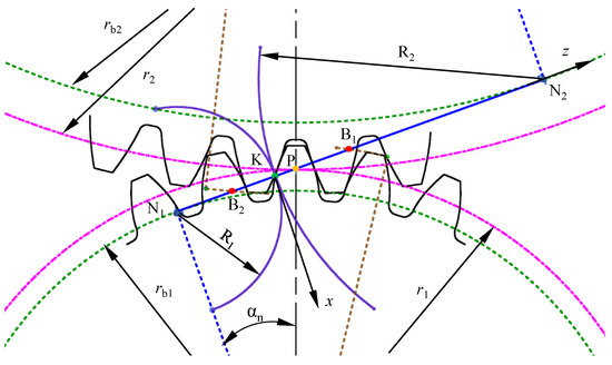
Figure 1.
The schematic of gear meshing.
2.2. Basic Equations for TEHL
Based on the works of Yang [37] and Huang [38], the fundamental equations for line-contact thermal elastohydrodynamic lubrication are as follows:
- (1)
- Reynolds Equationwhere p represents oil film pressure, h denotes oil film thickness, ρ stands for the film-thickness-averaged oil film density, η indicates the film-thickness-averaged lubricant viscosity and ue denotes the entrainment speed.Boundary conditions:where xin denotes the coordinate of the inlet region, and xout denotes the coordinate of the outlet region.
- (2)
- Film Thickness EquationThe film thickness equation for TEHL in gear line contact is as follows:where h0 denotes the central film thickness when the contacting bodies have not undergone elastic deformation, R denotes the effective radius of curvature, given by the following: .
- (3)
- Viscosity–Pressure–Temperature Equationwhere η represents the viscosity at pressure p and temperature T. η0 denotes the ambient viscosity, T0 denotes the ambient temperature, and T represents the oil film temperature.
- (4)
- Density–Pressure–Temperature Equationwhere ρ represents the density at pressure p and temperature T, ρ0 denotes the ambient density, and D represents the density–temperature coefficient.
- (5)
- Load Balance Equationwhere w represents the unit length load.
- (6)
- Energy EquationIn gear lubrication processes, the oil film temperature field can be determined through the energy equation and temperature conditions at the interfaces of the pinion and gear. The energy equation in line contact TEHL is expressed as follows:where z represents the coordinate in the film thickness direction, cp denotes the specific heat capacity of the fluid, k represents the thermal conductivity of the fluid, u denotes the fluid flow velocity in the x direction, and ω represents the fluid flow velocity in the z direction.Boundary conditions:where ρ1 and ρ2 represent the density of the pinion and gear, respectively, c1 and c2 represent the specific heat capacity of the pinion and gear, respectively, k1 and k2 represent the thermal conductivity of the pinion and gear, respectively, and u1 and u2 represent the tangential velocity along the x axis at the surfaces of the pinion and gear, respectively.The presence of the velocity component in the film-thickness direction in the energy equation introduces certain difficulties in solving the equation. This component can be eliminated using the fluid continuity equation. To solve the energy equation more efficiently, the velocity field and continuity equation required in the solution process are provided below. The specific steps for normalization and discretization of the equations can be found in Ref. [38].
- (7)
- Calculation of the Velocity FieldIn line contact, assuming the viscosity of the lubricant varies along the film thickness direction, the velocity in the x direction can be expressed as follows:The velocity gradient of the lubricant film in the film thickness direction can be expressed as follows:
- (8)
- Continuity EquationIn elastohydrodynamic lubrication problems, assuming the density of the lubricant does not vary with time, the continuity equation for line contact elastohydrodynamic lubrication can be derived as follows:After discretizing and normalizing the above equation, numerical methods are employed for solving it.
2.3. Numerical Methods
The numerical calculation process for TEHL is shown in Figure 2. The oil film pressure and film thickness distribution at various positions along the gear meshing line are solved using a multi-grid technique [39]. The pressure calculation region ranges from Xin = −4.6 to Xout= 1.4. During the analysis of pressure in each grid layer, the Gauss–Seidel iteration method is employed. The pressure-solving grid consists of 6 layers, with the topmost layer containing 961 nodes. Initially, the pressure values for the first iteration are set using Hertzian pressure. The pressure results from the previous time step are used as the initial values for the next time step. A W-cycle is employed, and the Reynolds equation is iteratively solved to obtain the converged oil film pressure and oil film thickness. The steady-state solution of the pressure is then used as the initial value to calculate the temperature for the current distribution, and it is determined whether the load balance condition is satisfied considering thermal effects. The oil film thickness is adjusted based on the relationship between oil film pressure and external load until load balance is achieved, yielding the distribution results for oil film pressure, oil film thickness, and temperature rise across each layer of the oil film.
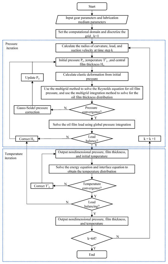
Figure 2.
Numerical calculation process of TEHL.
During the calculation, one meshing cycle is divided into 64 time steps, with pressure, load, and temperature dimensionless at different times. The criteria for judging the convergence of iterations are that the relative error between successive pressure iterations must be less than 0.001 and the relative error in temperature iteration must be less than 0.0001.
2.4. Comparison Between Empirical Formulas and Numerical Solutions
To assess whether the lubrication conditions of gears are satisfactory, it is necessary to calculate the minimum film thickness occurring in the gear meshing region. A commonly used formula for calculating the minimum oil film thickness is selected. The influence of input rotational speed and load on the minimum oil film thickness at the pitch point is investigated, and the results are compared with the numerical solution of TEHL in this study to further validate the accuracy of the calculated results. The commonly used empirical formulas for the minimum oil film thickness are as follows:
Dowson’s Minimum Oil Film Thickness Formula [40]:
Yang’s Minimum Oil Film Thickness Formula [41]:
For the given gear system, the original gear parameters and lubricant properties used in the calculations are shown in Table 1.

Table 1.
Gear parameters and lubricating oil parameters.
When the maximum unit length line load is 3 × 10⁵ N/m and the initial viscosity of the lubricant is 0.04 Pa·s, the effect of rotational speed on the minimum oil film thickness at the pitch point is shown in Figure 3.
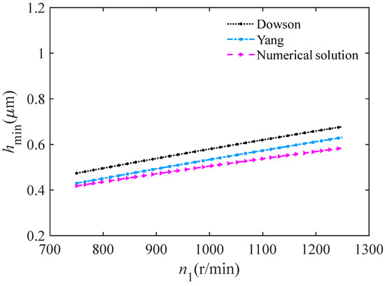
Figure 3.
Effect of rotational speed on minimum oil film thickness at the pitch point.
With the increase in input speed, the minimum oil film thickness gradually increases, which is in accordance with the general trend of elastohydrodynamic theory. Comparing the isothermal solutions of various empirical formulas with the TEHL solutions, it can be observed that the Dowson formula gives slightly larger results than the Yang formula. This is because the Dowson formula uses the Barus viscosity–pressure relationship, which tends to overestimate viscosity under high-pressure conditions. On the other hand, the Yang formula employs the Roelands viscosity–pressure relationship, which aligns well with experimental data when the pressure approaches 1 GPa. In the gear meshing process, relative sliding of the tooth surfaces, along with the load-induced friction, generates heat, causing a significant rise in lubricant temperature. This temperature increase results in the actual viscosity of the lubricant being lower than the initial viscosity, which is why the oil film thickness predicted by the TEHL numerical solution is lower than that of the empirical formulas.
Figure 4 illustrates the effect of the maximum unit length line load on the minimum oil film thickness at the pitch point when the input speed is n1 = 1000 r/min and the initial viscosity of the lubricant is 0.04 Pa·s. Theoretical analysis shows that the minimum oil film thickness, as indicated by Equations (12) and (13), exhibits a negative exponential relationship with load. This leads to a significant decrease in minimum oil film thickness as the line load increases. This phenomenon is caused by the abrupt change in the gap morphology at the outer edge of the contact area: as the load increases, the rapidly expanding gap geometry induces a sudden oil film contraction, resulting in a typical oil film necking effect. The secondary pressure peak caused by the dynamic pressure in this process intensifies significantly with increasing load. A comparison of different calculation methods reveals that the Dowson formula yields higher results, while the thermohydrodynamic lubrication solution and the Yang formula show good agreement in their predictions.
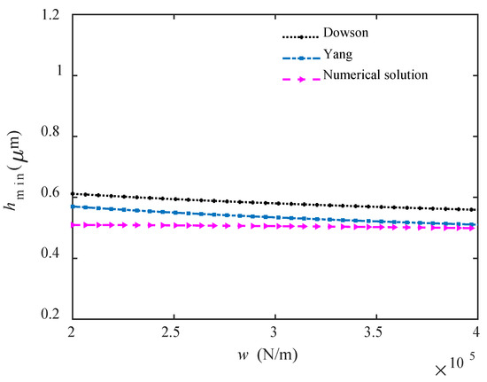
Figure 4.
Effect of load on minimum oil film thickness at the pitch point.
3. Analysis of Gear Stiffness Characteristics Based on TEHL
3.1. Calculation of Mesh Stiffness of Gears
Using the Weber energy method, calculate the mesh stiffness of gears. The two-dimensional cross-section cantilever beam model of spur gear teeth is shown in Figure 5. F is the meshing force perpendicular to the tooth surface, h is half of the tooth thickness at the meshing force location, αm is the angle between the meshing force and the direction of the tooth thickness, d is the distance from the meshing force location to the fixed part of the root circle, and dx and 2hx are the width and length of the micro-section at position x from the meshing force location, respectively.
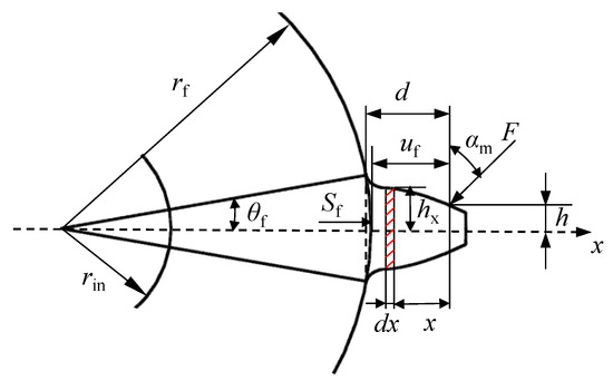
Figure 5.
Cantilever beam model of spur gear teeth with non-uniform cross-section.
Under the action of meshing force F, the stored elastic potential energy due to bending deformation, shear deformation, and axial compression deformation along the tooth height direction are respectively represented as follows:
where Kb, Ks, and Ka represent the equivalent spring stiffnesses corresponding to gear tooth bending deformation, shear deformation, and axial compression deformation along the line of contact, respectively.
According to beam deformation theory in mechanics of materials, the potential energies stored in gear teeth due to bending, shear, and axial compression deformations under the action of meshing force F are:
where Fb = Fcosαm: the forces along the gear tooth thickness direction;
Fa = Fsinαm: the force perpendicular to the tooth thickness direction;
M = Fbx − Fah: the moment relative to a small section of width dx.
The calculation expression for the bending stiffness Kb can be obtained from Equations (14) and (15) as follows:
The calculation expression for the shear stiffness Ks is as follows:
The calculation expression for the axial compression stiffness Ka is as follows:
where E: elastic modulus;
: shear modulus;
: the moment of inertia of the cross-section at a distance x from the point of application of the meshing force;
: the cross-sectional area at a distance x from the point of application of the meshing force.
Hertzian contact stiffness Kh can be calculated as follows:
The expression for calculating the deformation of gear tooth is as follows:
where B is the tooth width, uf and Sf are as shown in Figure 5, and coefficients L*, M*, P*, and Q* are approximated by polynomials:
where X* represents the coefficients L*, M*, P*, and Q*; hfi = rf/rin; rf, rin, and θf are shown in Figure 5, and the values of Ai, Bi, Ci, Di, Ei, and Fi are given in Table 2.
Combining the equivalent stiffness on the meshing line corresponding to the five deformations calculated above, the single tooth meshing stiffness of the gear pair can be expressed as follows:
where p and g represent the pinion and the gear in a pair of meshing gears, respectively.
Table 2.
Coefficient values in Equation (21) [42].
Table 2.
Coefficient values in Equation (21) [42].
| Ai | Bi | Ci | Di | Ei | Fi | |
|---|---|---|---|---|---|---|
| L*(hfi,θf) | −5.574 × 10⁻⁵ | −1.9986 × 10⁻³ | −2.0315 × 10⁻⁴ | 4.7702 × 10⁻³ | 0.0271 | 6.8045 |
| M*(hfi,θf) | 60.111 × 10⁻⁵ | 28.100 × 10⁻³ | −83.431 × 10⁻⁴ | −9.9256 × 10⁻³ | 0.1624 | 0.9086 |
| P*(hfi,θf) | −50.952 × 10⁻⁵ | 185.50 × 10⁻³ | 0.0853 × 10⁻⁴ | 53.3 × 10⁻³ | 0.2895 | 0.9236 |
| Q*(hfi,θf) | −6.2042 × 10⁻⁵ | 9.0889 × 10⁻³ | −4.0964 × 10⁻⁴ | 7.8297 × 10⁻³ | −0.1472 | 0.6904 |
3.2. A Normal Oil Film Stiffness Model Based on TEHL
The oil film stiffness on the meshing tooth surface can be decomposed into tangential oil film stiffness along the tangential direction of the contact point and normal oil film stiffness along the meshing line. In this paper, “oil film stiffness” refers to the normal oil film stiffness. In TEHL, the oil film is compressed under load, leading to compressive deformation and balancing the applied load. Due to the viscosity and elasticity of the lubricating oil, it is generally equivalent to spring stiffness.
The calculation model for oil film stiffness is shown in Figure 6. During the calculation of oil film pressure and thickness using the multi-grid method, the oil film region is divided into several nodes. Assuming there are n nodes in the calculation area, when an external load w1 is applied, the oil film pressure at each node is p1i (i = 1,2,3, …, n) and the corresponding oil film thickness is h1i. When an external load w2 is applied, the oil film pressure at each node is p2i (i = 1,2,3, …, n) and the corresponding oil film thickness is h2i.
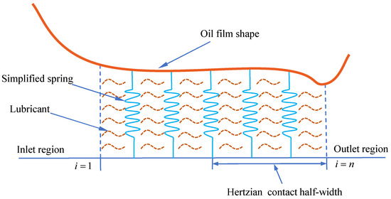
Figure 6.
Oil film stiffness calculation model.
The oil film stiffness at a single node is given by the following:
where Δxₒᵢ represents the variation in elastic deformation at the node when the load increment is ΔFₒᵢ; Δx denotes the grid length divided within the contact area.
w is the line load. Under the load variation Δw, the changes in oil film pressure and thickness at different nodes in the contact area vary. These nodes can be equivalent to many small springs, and their stiffness values are summed to obtain the total stiffness at the meshing point. The oil film stiffness in the contact area is defined as follows:
where i = 1 and i = n correspond to the endpoint values of the Hertzian contact area.
Since the TEHL solutions are fully dimensionless, the calculation formula for oil film stiffness is as follows:
where pH is the maximum Hertzian contact pressure and b is the half-width of the Hertzian contact area.
3.3. A Comprehensive Stiffness Model of Gears Based on TEHL
Since both the meshing stiffness of the gear teeth and the oil film stiffness vary with the meshing time within one cycle, Km and Koil are expressed as functions of time t. Considering that the stiffness of the oil film and the gear teeth are in series, the normal comprehensive stiffness is calculated using Equation (27).
4. Analysis of Gear Dynamic Characteristics Based on TEHL
After obtaining the time-varying meshing stiffness and comprehensive stiffness of the gear pair, a six-degree-of-freedom dynamic model of the gear transmission system is established to study the system’s dynamic response. According to Newton’s second law, the dynamic differential equations of the gear system are established, and the Newmark-β method is used to obtain the numerical solution of the gear system’s vibration response. This allows for the analysis of the time-varying characteristics of dynamic transmission error, vibration velocity, and dynamic meshing force. The dynamic responses under conditions with and without lubrication are compared, and the dynamic characteristics of the gear transmission system under different operating conditions are studied.
4.1. Dynamic Model of the Gear Transmission System
Without considering tooth surface friction, the dynamic model of a single-stage involute spur gear pair is established, as shown in Figure 7.
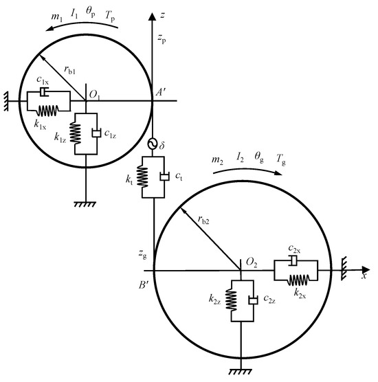
Figure 7.
Six-degree-of-freedom gear dynamic model.
The model is based on the following assumptions: (1) resonance of the gearbox housing is neglected; (2) the mass and inertia of the shafts are concentrated on the gears; (3) lateral vibration of the shafts is ignored; (4) shaft torsional stiffness is neglected; (5) the gear tooth profile is a standard involute with no errors; (6) the variation of contact ratio and the effect of contact extension during gear meshing are not considered.
4.2. Formulation of the Dynamic Differential Equations
Based on the six-degree-of-freedom dynamic model shown in Figure 7 and using Newton’s second law, the dynamic differential equations for the gear system are established.
where q is the vector of generalized displacements; m1 and m2 are the masses of the pinion and gear, respectively; I1 and I2 are the moments of inertia of the pinion and gear, respectively; k1x and k1z are the support stiffnesses in the x and z directions for the input shaft bearings, respectively; k2x and k2z are the support stiffnesses in the x and z directions for the output shaft bearings, respectively; c1x and c1z are the support damping coefficients in the x and z directions for the input shaft bearings, respectively; c2x and c2z are the support damping coefficients in the x and z directions for the output shaft bearings, respectively; Tp and Tg are the torques on the input and output shafts, respectively.
As an important indicator characterizing the dynamic excitation of gear transmission systems, transmission error is defined as the difference between the actual rotation angle of the driven gear and its theoretical rotation angle when the driving gear rotates through a certain angle. It is usually expressed in the form of linear displacement along the line of action. In dynamic analysis, the dynamic transmission error can be calculated by the following equation:
where θp and θg represent the torsional angular displacements of the pinion and the gear, respectively, and zp and zg denote the displacements of the pinion and the gear along the line of action at the meshing point, respectively.
Derivation of the dynamic transmission error gives the vibration velocity:
After obtaining the dynamic transmission error and vibration velocity of the gear, the dynamic meshing force Fd can be determined using Equation (31):
4.3. Dynamic Response Analysis of Gear Systems
Table 1 lists the original gear parameters and lubricant properties, while additional parameters required for the gear system dynamics calculation are provided in Table 3. The radial stiffnesses k1x, k1z, k2x, and k2z of the support bearing are simplified and are all equivalent to the stiffness kr; the radial damping c1x, c1z, c2x, and c2z of the support bearing are simplified and are all equivalent to the damping cr.
Table 3.
Main parameters of the gear system dynamic model.
To determine the meshing damping ct, this paper assumes a constant damping ratio ζ of 0.07. The meshing damping of the gear is proportional to the meshing stiffness:
where kave is the average meshing stiffness over one meshing cycle and cave is the average meshing damping over one meshing cycle.
The meshing damping ratio ζ can be expressed as follows:
where me is the equivalent mass of the gear transmission system,
.
By substituting the value of ζ into Equation (33), the average meshing damping over one meshing cycle can be obtained:
Coupled with Equations (32) and (34), the meshing damping of the gears can be expressed as follows:
4.3.1. Effect of Lubrication on the Dynamic Response Characteristics of the Gear System
The analysis presented in Figure 8 illustrates the influence of lubrication on the dynamic response characteristics of a gear transmission system, under a fixed input speed of n1 = 1000 r/min, a maximum line load per unit length of 3 × 10⁵ N/m, and an initial viscosity of the lubricating oil set at 0.04 Pa·s. When the effects of TEHL are taken into account, there is a notable increase in the dynamic transmission error along the meshing line, with its mean value increasing by approximately 60% compared to the uncoupled condition. This is mainly due to the fact that the comprehensive meshing stiffness of the gear pair is reduced after incorporating lubricant film stiffness. Concurrently, the vibration velocity along the meshing line exhibits a decrease, and the dynamic meshing force is significantly diminished in certain regions. This phenomenon can be attributed to the fact that, when considering the TEHL effect, the overall stiffness of the gear pair is reduced, while the dynamic transmission error along the meshing line increases. The interplay between these two factors plays a crucial role in determining the magnitude of the dynamic load experienced on the tooth surface. Consequently, the lubrication effect exerts a more pronounced influence on the vibrational characteristics of the system during dynamic analysis, underscoring the necessity of incorporating this factor into such evaluations.
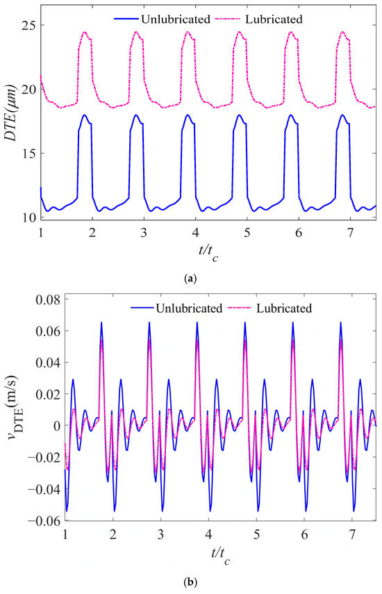
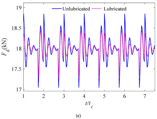
Figure 8.
Impact of lubrication on gear system dynamic response characteristics including (a) dynamic transmission error, (b) vibration velocity, and (c) dynamic meshing force.
The dynamic characteristics of gears are mainly determined by the fluctuation amplitude (represented by peak-to-peak value) of the transmission error curve under operating load, with larger amplitudes corresponding to more significant vibrations [43]. To further illustrate the influence of the lubricant film on the dynamic characteristics of gears, Table 4 presents the fluctuation amplitude variation rates of each dynamic response before and after lubrication. The results show that, compared to the unlubricated condition, the fluctuation amplitude of dynamic transmission error, vibration velocity, and dynamic meshing force are all reduced to varying degrees under the lubricated condition. Among them, the decreases in vibration velocity and meshing force are more pronounced. This further supports the necessity and significance of incorporating lubricant film stiffness into dynamic modeling. Moreover, the consistent downward trend across all three response metrics enhances the credibility of the results.
Table 4.
Fluctuation amplitude variation rates of dynamic parameters under unlubricated and lubricated conditions.
4.3.2. Influence of Speed on the Dynamic Response Characteristics of Gear System Under Lubrication Condition
The analysis presented in Figure 9 illustrates the influence of input speed on the dynamic response characteristics of a gear transmission system operating under lubrication conditions, with a maximum line load of 3 × 10⁵ N/m and an initial viscosity of the lubricating oil measured at 0.04 Pa·s. The data indicate that as the rotational speed increases, the ability of the two gear contact surfaces to form a lubricating oil film is significantly enhanced, resulting in an increase in oil film thickness. When the variation in oil film pressure is negligible, this thickening trend leads to a reduction in oil film stiffness. Since gear mesh stiffness is not directly affected by rotational speed, the overall stiffness, which combines oil film stiffness and gear mesh stiffness in series, decreases. This reduction has a suppressive effect on the dynamic meshing force. However, the increased rotational speed exacerbates the vibrations in the gear system, causing the amplitude of the dynamic transmission error and vibration velocity to increase. The combined effect of these vibrations and lubrication results in a rising trend in the system’s dynamic meshing force, thereby weakening the stability of the gear system.
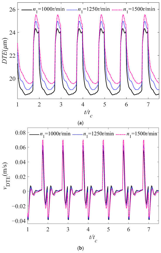
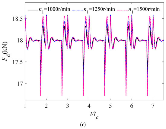
Figure 9.
Effect of speed on dynamic response characteristics of gear system under lubrication including (a) dynamic transmission error, (b) vibration velocity, and (c) dynamic meshing force.
4.3.3. Influence of Load on the Dynamic Response Characteristics of Gear System Under Lubrication Condition
At an input speed of 1000 r/min and an initial viscosity of the lubricating oil measured at 0.04 Pa·s, the influence of load on the dynamic response characteristics of the gear transmission system under lubrication is depicted in Figure 10. The data presented in Figure 10 indicate that the load significantly affects the dynamic characteristics of the gear transmission system. As the load increases, both the dynamic transmission error and the amplitude of vibration velocity exhibit a gradually increasing trend. Since oil film pressure is primarily influenced by the load, and the sensitivity of oil film thickness to load variations is relatively low, an increase in load leads to an enhancement in oil film stiffness. Under the combined effects of vibration velocity, overall stiffness, and dynamic transmission error, the dynamic meshing force also increases significantly.
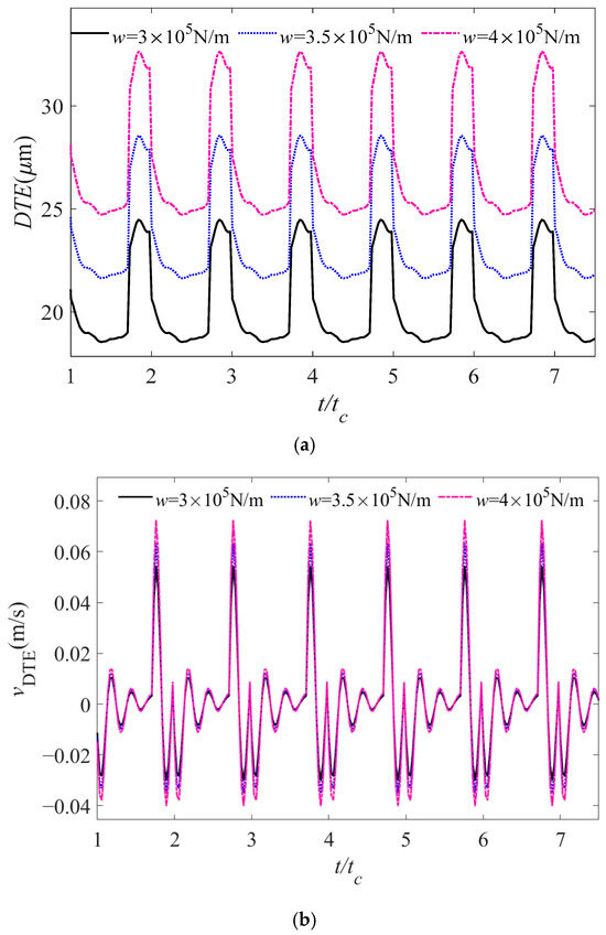
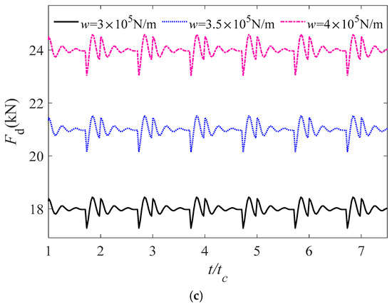
Figure 10.
Effect of load on dynamic response characteristics of gear system under lubrication including (a) dynamic transmission error, (b) vibration velocity, and (c) dynamic meshing force.
4.3.4. Influence of Initial Viscosity on the Dynamic Response Characteristics of Gear System Under Lubrication Condition
At an input speed of 1000 r/min and a maximum line load of 3 × 10⁵ N/m, the influence of the initial viscosity of the lubricating oil on the dynamic response characteristics of the gear transmission system in a lubricated state is illustrated in Figure 11. The data presented in Figure 11 indicate that an increase in the initial viscosity of lubricating oil has little impact on the average of the dynamic transmission error but can significantly reduce its fluctuation range. Meanwhile, the amplitude of vibration velocity slightly decreases, though the change is not significant. Higher initial viscosity facilitates the formation of an oil film between gear surfaces, leading to an increase in oil film thickness and a corresponding reduction in oil film stiffness. This change further results in a moderate decrease in the dynamic meshing force.
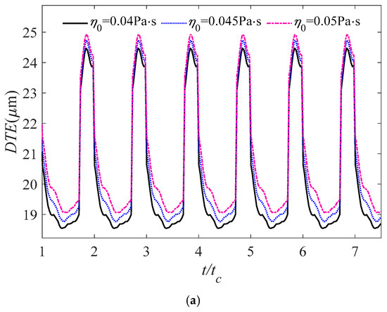
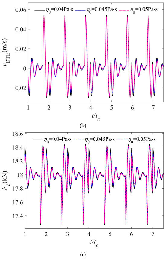
Figure 11.
Effect of initial viscosity on dynamic response characteristics of gear system under lubrication including (a) dynamic transmission error, (b) vibration velocity, and (c) dynamic meshing force.
5. Conclusions
This study addresses the critical role of lubrication effects in gear dynamics. Against the backdrop of increasing demands for accurate gear transmission models, the research identifies the need to integrate oil film stiffness into dynamic analyses to improve the representation of real-world operating conditions. To this end, the study develops a TEHL-based oil film stiffness model, combines it with meshing stiffness, and investigates the dynamic characteristics of gear systems under various operating conditions. The finding of this paper can be summarized as follows:
- (1)
- Taking into account the TEHL effect, it has been observed that the dynamic transmission error along the gear meshing line exhibits an increase, particularly within the double-tooth engagement region. Compared to the model without consideration of oil-film stiffness, the amplitudes of dynamic transmission error, vibration velocity, and dynamic meshing force all exhibit a certain degree of reduction when the oil film stiffness is included. When the oil film stiffness effects are incorporated into the analysis, the vibrational characteristics of the system become significantly more pronounced, necessitating their consideration in dynamic analyses.
- (2)
- As the rotational speed escalates, there is a corresponding increase in the amplitudes of dynamic transmission error, vibration velocity, and dynamic meshing force, which subsequently diminishes the stability of the gear transmission system.
- (3)
- As the load increases, there is a corresponding rise in the amplitudes of dynamic transmission error, vibration velocity, and dynamic meshing force, which subsequently diminishes the stability of the gear transmission system. The dynamic meshing force experiences a significant escalation in response to elevated external loads. In the context of heavily loaded gear systems, it is essential to account for the effects of TEHL on the dynamic characteristics.
- (4)
- An increase in the initial viscosity of lubricating oil is associated with a reduction in the fluctuations of the dynamic transmission error, while the variations in vibration velocity and dynamic meshing force remain minimal. Consequently, under these circumstances, a judicious increase in the initial viscosity of the lubricating oil can improve the transmission stability of the gear system.
The limitations of this study lie in the assumption of a standard involute gear profile without considering profile errors, as well as the omission of nonlinear factors such as backlash and gear eccentricity in the dynamic modeling process. These limitations may not fully capture the complexity and transient nature of actual gear lubrication. Future work could involve developing a transient and more realistic method for calculating oil film stiffness and refining the dynamic model of gear systems. Experimental validation will also be conducted to ensure applicability to real-world engineering scenarios.
Author Contributions
Software, Y.Y.; Formal analysis, Y.L.; Investigation, Z.H.; Writing—original draft, X.W.; Supervision, Z.H. All authors have read and agreed to the published version of the manuscript.
Funding
This research was funded by Xi’an Science and Technology Plan Key Industrial Chain Key & Core Technology Research Project 23LLRH0079.
Data Availability Statement
The original contributions presented in the study are included in the article, further inquiries can be directed to the corresponding author.
Conflicts of Interest
The authors declare no confliict of interest.
Nomenclature
| B | gear width | rb1,rb2 | base circle radii of pinion and gear |
| b | half-width of Hertzian contact area | T | oil film temperature |
| c1,c2 | specific heat capacity of pinion and gear | T0 | ambient temperature |
| cp | specific heat capacity of lubricant | Tp,Tg | input torque and output torque |
| ct | meshing damping | ue | entrainment speed |
| D | density–temperature coefficient | u | fluid flow velocity in the x direction |
| E1,E2 | elastic modulus of pinion and gear | u1,u2 | tangential velocity of the pinion and gear |
| E | comprehensive elastic modulus | U | dimensionless entrainment speed |
| F | meshing force | vDTE | vibration velocity |
| Fa,Fb | components of meshing force | w | load per unit length |
| Fd | dynamic meshing force | W | dimensionless load |
| G | material parameter | Δx | grid length |
| h | oil film thickness | z1,z2 | number of teeth of pinion and gear |
| h0 | central film thickness | ω | fluid flow velocity in the z direction |
| hmin | minimum oil film thickness | η | dynamic viscosity of lubricant |
| I1,I2 | moment of inertia of pinion and gear | η0 | ambient viscosity |
| k | thermal conductivity of lubricant | ν1,ν2 | ambient viscosity |
| k1,k2 | thermal conductivity of pinion and gear | ρ | oil film density |
| Koi | single node oil film stiffness | ρ0 | ambient oil density |
| koil | contact area oil film stiffness | ρ1,ρ2 | density of pinion and gear |
| Km | gear meshing stiffness | ζ | meshing damping ratio |
| Kc | normal comprehensive stiffness | ||
| m | gear module | ||
| m1,m2 | mass of pinion and gear | ||
| me | equivalent mass of gear system | ||
| p | oil film pressure | ||
| pH | maximum Hertzian contact pressure | ||
| R1,R2 | curvature radii of pinion and gear | ||
| R | equivalent radius of curvature | ||
| r1,r2 | pitch circle radii of pinion and gear |
References
- Marian, M.; Bartz, M.; Wartzack, S.; Rosenkranz, A. Non-Dimensional Groups, Film Thickness Equations and Correction Factors for Elastohydrodynamic Lubrication: A Review. Lubricants 2020, 8, 95. [Google Scholar] [CrossRef]
- Lu, R.; Tang, W.; Huang, Q.; Xie, J. An Improved Load Distribution Model for Gear Transmission in Thermal Elastohydrodynamic Lubrication. Lubricants 2023, 11, 177. [Google Scholar] [CrossRef]
- Dong, G. Damping Characteristics of Thermal Elastohydrodynamic Lubricated Point Contacts. J. Braz. Soc. Mech. Sci. Eng. 2021, 43, 137. [Google Scholar] [CrossRef]
- Zhou, Y.; Zhu, C.; Liu, H. A Micropitting Study Considering Rough Sliding and Mild Wear. Coatings 2019, 9, 639. [Google Scholar] [CrossRef]
- Fang, C.; Zhu, A.; Zhou, W.; Peng, Y.; Meng, X. On the Stiffness and Damping Characteristics of Line Contacts under Transient Elastohydrodynamic Lubrication. Lubricants 2022, 10, 73. [Google Scholar] [CrossRef]
- Habchi, W. Coupling Strategies for Finite Element Modeling of Thermal Elastohydrodynamic Lubrication Problems. J. Tribol. 2017, 139, 041501. [Google Scholar] [CrossRef]
- Amine, G.; Fillot, N.; Philippon, D.; Devaux, N.; Dufils, J.; Macron, E. Dual Experimental-Numerical Study of Oil Film Thickness and Friction in a Wide Elliptical TEHL Contact: From Pure Rolling to Opposite Sliding. Tribol. Int. 2023, 184, 108466. [Google Scholar] [CrossRef]
- Havaej, P.; Degroote, J.; Fauconnier, D. A Quantitative Analysis of Double-Sided Surface Waviness on TEHL Line Contacts. Tribol. Int. 2023, 183, 108389. [Google Scholar] [CrossRef]
- Huang, X.; Yang, B.; Wang, Y. A Nano-Lubrication Solution for High-Speed Heavy-Loaded Spur Gears and Stiffness Modelling. Appl. Math. Model. 2019, 72, 623–649. [Google Scholar] [CrossRef]
- Hultqvist, T.; Vrcek, A.; Marklund, P.; Prakash, B.; Larsson, R. Transient Analysis of Surface Roughness Features in Thermal Elastohydrodynamic Contacts. Tribol. Int. 2020, 141, 105915. [Google Scholar] [CrossRef]
- Zhao, Z.; Yang, Y.; Han, H.; Ma, H.; Wang, H.; Li, Z. Meshing Characteristics of Spur Gears Considering Three-Dimensional Fractal Rough Surface under Elastohydrodynamic Lubrication. Machines 2022, 10, 705. [Google Scholar] [CrossRef]
- Li, S.; Kahraman, A. A Scuffing Model for Spur Gear Contacts. Mech. Mach. Theory 2021, 156, 104161. [Google Scholar] [CrossRef]
- Ziegltrum, A.; Lohner, T.; Stahl, K. TEHL Simulation on the Influence of Lubricants on Load-Dependent Gear Losses. Tribol. Int. 2017, 113, 252–261. [Google Scholar] [CrossRef]
- Natali, C.; Battarra, M.; Dalpiaz, G.; Mucchi, E. A Critical Review on FE-Based Methods for Mesh Stiffness Estimation in Spur Gears. Mech. Mach. Theory 2021, 161, 104319. [Google Scholar] [CrossRef]
- Xu, L.; Luo, Y.; Hu, R. A Novel Method of Modelling Contact Dynamics for Spur Gear Transmission. Mech. Mach. Theory 2024, 203, 105793. [Google Scholar] [CrossRef]
- Kumar, V.; Kumar, A.; Kumar, S.; Sarangi, S. TVMS Calculation and Dynamic Analysis of Carburized Spur Gear Pair. Mech. Syst. Signal Process. 2022, 166, 108436. [Google Scholar] [CrossRef]
- Xie, C.; Shu, X. A New Mesh Stiffness Model for Modified Spur Gears with Coupling Tooth and Body Flexibility Effects. Appl. Math. Model. 2021, 91, 1194–1210. [Google Scholar] [CrossRef]
- Wang, J.; Yang, J.; Lin, Y.; He, Y. Analytical Investigation of Profile Shifts on the Mesh Stiffness and Dynamic Characteristics of Spur Gears. Mech. Mach. Theory 2022, 167, 104529. [Google Scholar] [CrossRef]
- Guan, X.; Tang, J.; Hu, Z.; Wang, Q.; Kong, X. A New Dynamic Model of Light-Weight Spur Gear Transmission System Considering the Elasticity of the Shaft and Gear Body. Mech. Mach. Theory 2022, 170, 104689. [Google Scholar] [CrossRef]
- Kong, X.; Tang, J.; Hu, Z.; Ding, H.; Wang, Z.; Wang, Q. Dynamic Modeling and Vibration Analysis of Spur Gear System Considering Thin-Walled Gear and Hollow Shaft. Mech. Mach. Theory 2023, 181, 105197. [Google Scholar] [CrossRef]
- Wei, S.; Chu, F.-L.; Ding, H.; Chen, L.-Q. Dynamic Analysis of Uncertain Spur Gear Systems. Mech. Syst. Signal Process. 2021, 150, 107280. [Google Scholar] [CrossRef]
- Zhao, Z.; Han, H.; Wang, P.; Ma, H.; Zhang, S.; Yang, Y. An Improved Model for Meshing Characteristics Analysis of Spur Gears Considering Fractal Surface Contact and Friction. Mech. Mach. Theory 2021, 158, 104219. [Google Scholar] [CrossRef]
- Huangfu, Y.; Chen, K.; Ma, H.; Li, X.; Han, H.; Zhao, Z. Meshing and Dynamic Characteristics Analysis of Spalled Gear Systems: A Theoretical and Experimental Study. Mech. Syst. Signal Process. 2020, 139, 106640. [Google Scholar] [CrossRef]
- Chen, K.; Huangfu, Y.; Ma, H.; Xu, Z.; Li, X.; Wen, B. Calculation of Mesh Stiffness of Spur Gears Considering Complex Foundation Types and Crack Propagation Paths. Mech. Syst. Signal Process. 2019, 130, 273–292. [Google Scholar] [CrossRef]
- Chen, Z.; Ning, J.; Wang, K.; Zhai, W. An Improved Dynamic Model of Spur Gear Transmission Considering Coupling Effect between Gear Neighboring Teeth. Nonlinear Dyn. 2021, 106, 339–357. [Google Scholar] [CrossRef]
- Kalay, O.C.; Doğan, O.; Yılmaz, T.G.; Yüce, C.; Karpat, F. A Comparative Experimental Study on the Impact Strength of Standard and Asymmetric Involute Spur Gears. Measurement 2021, 172, 108950. [Google Scholar] [CrossRef]
- Gao, P.; Liu, H.; Yan, P.; Xie, Y.; Xiang, C.; Wang, C. Research on Application of Dynamic Optimization Modification for an Involute Spur Gear in a Fixed-Shaft Gear Transmission System. Mech. Syst. Signal Process. 2022, 181, 109530. [Google Scholar] [CrossRef]
- Xiao, Z.; Zhou, C.; Chen, S.; Li, Z. Effects of Oil Film Stiffness and Damping on Spur Gear Dynamics. Nonlinear Dyn. 2019, 96, 145–159. [Google Scholar] [CrossRef]
- Zhou, C.; Xiao, Z.; Chen, S.; Han, X. Normal and Tangential Oil Film Stiffness of Modified Spur Gear with Non-Newtonian Elastohydrodynamic Lubrication. Tribol. Int. 2017, 109, 319–327. [Google Scholar] [CrossRef]
- Li, Z.; Zhu, C.; Liu, H.; Gu, Z. Mesh Stiffness and Nonlinear Dynamic Response of a Spur Gear Pair Considering Tribo-Dynamic Effect. Mech. Mach. Theory 2020, 153, 103989. [Google Scholar] [CrossRef]
- Ouyang, T.; Huang, G.; Chen, J.; Gao, B.; Chen, N. Investigation of Lubricating and Dynamic Performances for High-Speed Spur Gear Based on Tribo-Dynamic theory. Tribol. Int. 2019, 136, 421–431. [Google Scholar] [CrossRef]
- Zhou, C.; Xiao, Z. Stiffness and Damping Models for the Oil Film in Line Contact Elastohydrodynamic Lubrication and Applications in the Gear Drive. Appl. Math. Model. 2018, 61, 634–649. [Google Scholar] [CrossRef]
- Zhou, C.; Xing, M.; Hu, B. A Mesh Stiffness Model with the Asperity Contact for Spur Gear in Mixed Elastohydrodynamic Lubrication. J. Braz. Soc. Mech. Sci. Eng. 2022, 44, 466. [Google Scholar] [CrossRef]
- Yang, X.; Tofighi-Niaki, E.; Zuo, M.J.; Tian, Z.; Safizadeh, M.S.; Qin, D. Analysis of Spur Gearbox Dynamics Considering Tooth Lubrication and Tooth Crack Severity Progression. Tribol. Int. 2023, 178, 108027. [Google Scholar] [CrossRef]
- Jian, G.; Wang, Y.; Zhang, P.; Xie, Y.; Zhao, J. Analysis of Lubricating Performance for Involute Spur Gear under Vibration. Lubr. Sci. 2020, 32, 344–357. [Google Scholar] [CrossRef]
- Liguori, A.; Armentani, E.; Bertocco, A.; Formato, A.; Pellegrino, A.; Villecco, F. Noise Reduction in Spur Gear Systems. Entropy 2020, 22, 1306. [Google Scholar] [CrossRef]
- Yang, P.; Wen, S. A Generalized Reynolds Equation for Non-Newtonian Thermal Elastohydrodynamic Lubrication. J. Tribol. 1990, 112, 631–636. [Google Scholar] [CrossRef]
- Huang, P. Numerical Calculation of Elastohydrodynamic Lubrication: Methods and Programs; John Wiley & Sons: Hoboken, NJ, USA, 2015; ISBN 1-118-92099-6. [Google Scholar]
- Huang, P. Numerical Calculation Methods of Elastohydrodynamic Lubrication; Tsinghua University Press: Beijing, China, 2013. [Google Scholar]
- Dowson, D. Elastohydrodynamics. Proc. Inst. Mech. Eng. Conf. Proc. 1967, 182, 151–167. [Google Scholar] [CrossRef]
- Yang, P.; Wen, S. A New Solution Method for Line Contact Elastohydrodynamic Lubrication Problems and a More Accurate Film Thickness Formula; Tsinghua University Science Reports; Tsinghua University: Beijing, China, 1988. [Google Scholar]
- Sainsot, P.; Velex, P.; Duverger, O. Contribution of Gear Body to Tooth Deflections—A New Bidimensional Analytical Formula. J. Mech. Des. 2004, 126, 748–752. [Google Scholar] [CrossRef]
- Cao, X.; Zhou, Y.; Deng, X.; Zhang, H. Relationship Among Transmission Error, Contact Ratio and Noise of Spiral Bevel Gears. J. Henan Univ. Sci. Technol. Nat. Sci. 2003, 24, 16–19. [Google Scholar] [CrossRef]


Disclaimer/Publisher’s Note: The statements, opinions and data contained in all publications are solely those of the individual author(s) and contributor(s) and not of MDPI and/or the editor(s). MDPI and/or the editor(s) disclaim responsibility for any injury to people or property resulting from any ideas, methods, instructions or products referred to in the content. |
© 2025 by the authors. Licensee MDPI, Basel, Switzerland. This article is an open access article distributed under the terms and conditions of the Creative Commons Attribution (CC BY) license (https://creativecommons.org/licenses/by/4.0/).