Article

Thermal Elastohydrodynamic Lubrication Analysis of Grease in Tripod Sliding Universal Couplings

1
College of Mechanical and Automotive Engineering, Qingdao Hengxing University of Science and Technology, Qingdao 266100, China
2
College of Science, Qingdao University of Technology, Qingdao 266033, China
*
Author to whom correspondence should be addressed.
Lubricants 2025, 13(9), 400; https://doi.org/10.3390/lubricants13090400
Submission received: 25 July 2025 / Revised: 23 August 2025 / Accepted: 5 September 2025 / Published: 9 September 2025
(This article belongs to the Special Issue Modeling and Simulation of Elastohydrodynamic Lubrication)

Abstract

The tripod sliding universal coupling (TSUC) is a novel type of coupling developed through independent research. This study theoretically investigates the effects of the grease flow index and initial viscosity on thermal elastohydrodynamic lubrication (TEHL) properties. Three common grease formulations were evaluated for TSUC lubrication. The numerical results yielded the following insights: a larger flow index increases film thickness and elevates the secondary pressure peak. A higher initial viscosity enhances film thickness yet significantly elevates the temperature distribution due to quadratic growth in viscous dissipation. It also intensifies the secondary pressure peak, which may exceed the central Hertzian pressure under heavy loads, thereby accelerating surface fatigue. The lubrication performance varies significantly across grease types. When pressure–viscosity coefficients and densities are similar, the initial viscosity becomes the dominant factor. These findings provide a theoretical basis for optimizing grease selection in TSUC systems to improve the efficiency and durability of lubrication.

1. Introduction

The tripod sliding universal coupling (TSUC) is a novel type of coupling developed through independent research. This innovative structure includes key components such as a tripod sleeve, sliding rods, coupling bearings, and a tripod, as illustrated in Figure 1. Under sustained operation, however, high-frequency reciprocating motion under load induces substantial interfacial friction and wear at the tripod sleeve hole/sliding rod contact zones. This accelerated surface degradation directly limits the coupling’s operational lifespan. Concurrent thermal effects compound this wear mechanism: elevated operating temperatures reduce the viscosity of lubricating grease in these critical interfaces, further impairing tribological performance. Crucially, grease rheology (i.e., viscosity–temperature dependence and shear thinning) and thickener microstructure govern the stability and wear resistance of TEHL films in TSUC systems. A systematic investigation into grease property–TEHL performance correlations is therefore essential. Optimized grease selection based on such research has substantial potential to extend the service life of these systems while enhancing their operational durability.
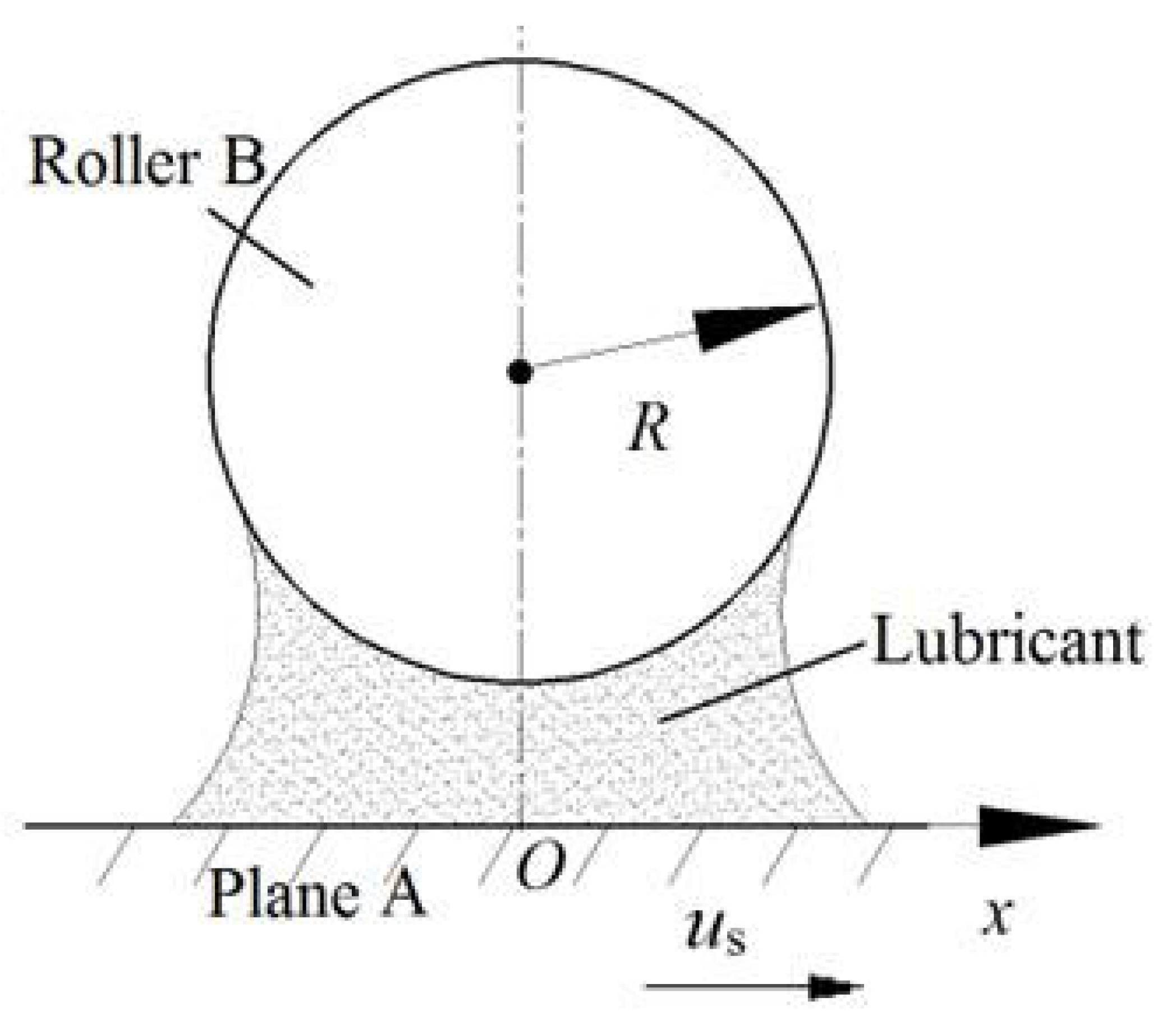
To improve the lubrication performance, a wear-resistant surface topology was developed. The sliding rod was redesigned with a novel configuration featuring multiple parallel annular protrusions on the cylindrical base (Figure 1). Figure 2 provides a cross-sectional view of the mating surface between this wear-resistant sliding pin and the tripod sleeve hole. Since the radius of the tripod sleeve hole significantly exceeds that of the annular protrusion in the reciprocating motion direction, the contact region near the maximum-radius cross-section of the annular protrusion approximates a circular arc. Given that the arc length is substantially greater than the Hertz contact radius, arc bending can be neglected. Consequently, the geometry was simplified to a model comprising Plane A and an infinitely long Cylinder B, as shown in Figure 3. Wang et al. have previously validated the feasibility of this geometric simplification [1]. Considering the lubrication between the tripod sleeve hole and the sliding rod as a grease TEHL problem under the influence of relative reciprocating motion, the cited authors simplified the model to a contact analysis between a plane and an infinitely long cylinder [1]. This is a grease TEHL line contact problem, and significant fundamental research has already been conducted in this context. Several studies have been conducted to explore TEHL mechanisms. Sadeghi et al. [2] examined the thermal and compressible TEHL behaviors under the influence of rolling and sliding contacts, evaluating how variations in load, velocity, and slip ratio affect the lubricant’s temperature, film thickness, and friction force. Yoo et al. [3] conducted a study on the impact of temperature and flow indices on the TEHL of grease, employing the Herschel–Bulkley model in their analysis. Kaneta et al. [4] examined the effect of thickener microstructure and base oil viscosity on the formation and stability of grease films. Wang et al. [5] addressed the line contact problem of oil TEHL under the influence of reciprocating motion through the application of numerical calculation methods. Yu et al. [6] investigated the lubrication effect of TEHL grease in line contacts subjected to reciprocating motion. Wang et al. [7] explored how lubricant viscosity, effective elastic modulus, and applied load affect the thickness and pressure distribution of the film. Furthermore, Chang et al. [8] emphasized the critical role of thermal effects in determining the lubrication behavior of the TSUC. Wang et al. [9] examined how frequency and amplitude affect film thickness, pressure, and temperature. Yang et al. [10] applied TEHL theory to optimize the tribological performance of a ball-type tripod universal joint. Yang et al. [11] optimized micro-groove geometric parameters (depth, width, and inclination) using Kriging and NCGA to improve the lubrication of tripod universal couplings. Laura et al. [12] investigated temperature-dependent wear protection mechanisms in grease-lubricated roller bearings, revealing critical medium-temperature vulnerability (40–60 °C) due to insufficient tribofilm formation. Additionally, Wang et al. [13] studied how microtextural parameters (size, shape, and orientation) influence bearing performance characteristics such as load capacity, frictional behavior, end leakage, and oil film characteristics. The aforementioned pioneering works primarily focused on exploring the fundamentals and lubricating properties of grease in TEHL contacts. Despite these advances, a systematic friction–lubrication theory specific to TSUC interfaces remains unestablished, with limited dedicated studies. Research on grease lubrication mechanisms at TSUC tribological interfaces provides theoretical foundations for performance enhancement and supports future coupling applications.

2. Numerical Simulation

2.1. Governing Equations

Considering the lubrication characteristics of the coupling at maximum operational speed, the relative reciprocating entrainment velocity at the mating surface (between the sliding pin and the tripod sleeve hole) governs the formation of the TEHL film. This velocity is defined as follows:
u = A ω sin ω t = A 2 π f sin ( 2 π f t )
At present, the material equations used to determine the rheological behavior of lubricating grease are commonly characterized using three primary models: the Ostwald, Bingham, and Herschel–Bulkley models [14]. There is a great deal of experimental evidence indicating that the Herschel–Bulkley model aligns most closely with the actual behavior of grease [15]. However, due to the presence of yield shear stress in the corresponding equation, the lubricating film is divided into two parts: a non-shear-flow layer and a shear flow layer. This requires separate calculations, making the calculation process more complex [16,17].
The authors of [18] suggested that 80% of generalized Newton bodies in industrial applications can be calculated using the Ostwald model. This model is not as accurate as the Herschel–Bulkley model; however, the results obtained when using these two models are similar. Owing to the simplicity of its constitutive equation—which depends solely on the consistency coefficient ϕ and flow behavior index n—the Ostwald model enables convenient calculations and reproducible results, making it broadly applicable to lipid rheological studies. Therefore, the control equation for grease lubrication was formulated based on the rheological characteristics defined by the Ostwald model.
Based on the rheological properties of grease defined according to the constitutive equation of the Ostwald model, the Reynolds equation proposed by Huang [19] is defined as follows:
n 2 n + 1 1 2 n + 1 n d d x ρ h 2 n + 1 n ( 1 φ d p d x ) 1 n = u d ( ρ h ) d x
Here,
p ( x 0 , t ) = 0 , p ( x e , t ) = 0 , p 0 ( x 0 < x < x e )
The film thickness equation, which accounts for surface deformation and geometry, is expressed as
h ( x ) = h 0 + x 2 2 R 2 π E x 0 x e p ( x ) ln ( x x ) 2 d x
Considering thermal effects, the energy equation proposed by Huang [13] takes the following form:
ρ c u T x = k 2 T z 2 T ρ ρ T u p x + φ ( u z ) 2
The boundary conditions imposed on the upper and lower surfaces are
T ( x , 0 ) = k π ρ 1 c 1 k 1 u 1 x T z | x , 0 d s x s + T 0
T ( x , h ) = k π ρ 2 c 2 k 2 u 2 x T z | x , h d s x s + T 0
Here, the grease viscosity–pressure temperature equation is calculated as follows:
φ = φ 0 exp { ( ln φ 0 + 9.67 [ ( 1 + p / p 0 ) 0.68 × ( T 138 T 0 138 ) 1.1 1 ] ) }
In Equation (5), z = α / 5.1 × 1 0 9 × ( ln φ 0 + 9.67 ) .
The relationship between density and pressure is expressed as follows:
ρ = ρ 0 [ 1 + 0.6 × 1 0 9 p 1 + 1.7 × 1 0 9 p 6.5 × 1 0 4 × ( T T 0 ) ]
When the applied load remains constant, the load model accounting for the distribution of the load across the contact area simplifies to the following:
x 0 x e p ( x ) d x = w

2.2. Numerical Method

In numerical simulations, Equations (2)–(7) are first transformed into dimensionless forms. The dimensionless pressure is P = p / p H , where pH denotes Hertz line contact pressures. The thickness of the dimensionless film is H = h R / b 2 . The dimensionless horizontal coordinate is X = x / b . The dimensionless velocity is denoted as U = φ 0 u s 2 E R and U 1 = φ 0 u 1 2 E R , U 2 = φ 0 u 2 2 E R , and 1 E = 1 2 ( 1 v 1 2 E 1 + 1 v 2 2 E 2 ) . The elastic moduli of the upper and lower surfaces are denoted by E1 and E2, respectively, while v1 and v2 represent the corresponding Poisson’s ratios. The dimensionless plastic viscosity is φ * = φ / φ 0 , and the dimensionless density is ρ * = ρ / ρ 0 . Finally, the dimensionless temperature is T * = T / T 0 .
With the influence of the roughness of the mating surface ignored, pressure and elastic deformation are calculated using a multigrid method, while the energy equation is solved via a step-by-step method iteratively corrected with 257 grid nodes [20]. The governing equations are addressed through a coupled pressure–temperature iteration [21,22]. First, the initial conditions—such as Hertzian contact pressure and a uniform temperature field—are defined. Subsequently, the lubricating grease’s film thickness, viscosity, and density are computed. A new pressure distribution is then solved using the Reynolds equation (Equation (2)). This pressure solution is iteratively corrected and applied to the energy equation (Equation (4)) to update the temperature field. The updated temperature values recalibrate viscosity and density, leading to a revised pressure solution. This cycle repeats until the relative pressure difference between consecutive iterations satisfies the convergence criterion. The final output comprises converged values of film thickness, temperature distribution, and pressure (incorporating elastic deformation).
The criterion for judging the convergence of the iterative solution is that the relative differences in load and temperature between consecutive iterations satisfy a prescribed tolerance. The specific implementation is as follows:
i j p i , j k + 1 i j p i , j k / i j p i , j k + 1 1 0 6
t i j T t , i , j k + 1 t i j T t , i , j k / t i j T t , i , j k + 1 1 0 5
In Equations (8) and (9), the superscripts k + 1 and k represent the current and previous iteration indices, respectively. The computation terminates when the convergence criterion is satisfied or when the major loop iteration count reaches 12, at which point the final values for lubricant film thickness, temperature distribution, and pressure distribution are output.

3. Results and Discussion

In the actual usage environment for couplings in automotive drive axles, at an angle of 4° between the central axis and the input axis, the amplitude A = 2 mm. For a car traveling at 200 km/h, the transmission shaft rotation frequency f = 30 Hz. At this point, the average speed of the lubricated interface is us = 0.188 m/s. Considering the lubrication properties during a stroke, the maximum value of minimum film thickness and the secondary pressure peak and lubricating film temperature all appear in the middle of the stroke. Consequently, a detailed investigation into the lubrication behavior of the TSUC at the midpoint of the stroke was performed. The global parameters in the calculating procedure include xe = −x0 = 3b m, E′ = 2.27 × 10¹¹ Pa, w = 80 kN/m, R = 10 mm, k = 0.14 W·m−1·K−1, k1 = 47 W·m−1·K−1, k2 = 47 W·m−1·K−1, c = 2000 J·kg−1·K−1, c1 = 470 J·kg−1·K−1, c2 = 470 J·kg−1·K−1, ρ1 = 7850 kg·m−3, and ρ2 = 7850 kg·m−3.
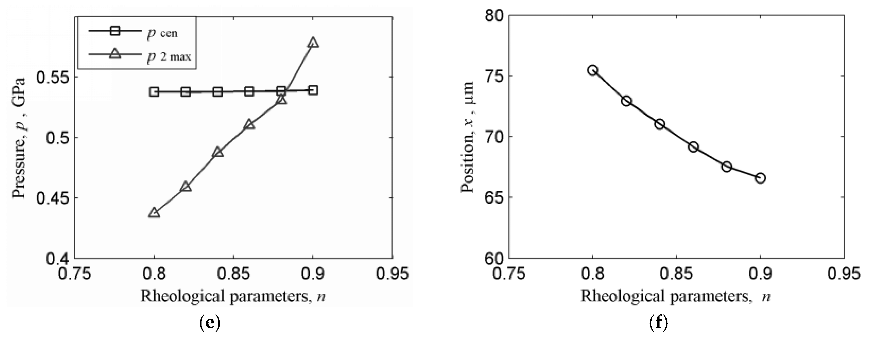
Figure 4 illustrates how changes in the grease flow index affect the pressure and thickness of the lubricating film. This is a key parameter characterizing the effect of shear-thinning non-Newtonian behavior on the pressure distribution and thickness of the lubricating film in EHL contacts. As illustrated in Figure 4a, an increase in the grease flow index correlates with greater overall film thickness. Both the central and minimum film thicknesses exhibit nonlinear growth, with the central thickness demonstrating a more pronounced increase (Figure 4b). This increase in film thickness is primarily due to the enhanced apparent viscosity of the grease in the low-shear-rate inlet zone when the grease flow index is larger, promoting more effective entrainment and hydrodynamic film formation. Figure 4d,e indicate that the maximum pressure of the secondary pressure peak rises with an increase in the flow index, while the central pressure decreases to maintain load equilibrium. These pressure changes are intrinsically linked: the elevated inlet viscosity, associated with a higher grease flow index, leads to hydrodynamic pressure build-up near the inlet, resulting in a stronger secondary pressure peak. To maintain overall load equilibrium across the contact, the contribution from the central pressure region must decrease. Collectively, Figure 4c,f demonstrate that higher grease flow index values shift both the location of the minimum film thickness and the positions of the secondary pressure and temperature peaks toward the inlet zone. The secondary pressure peak is located slightly upstream of the minimum film thickness. This shift occurs because the strengthened, more viscous fluid wedge that forms near the inlet extends its influence further upstream as n increases.
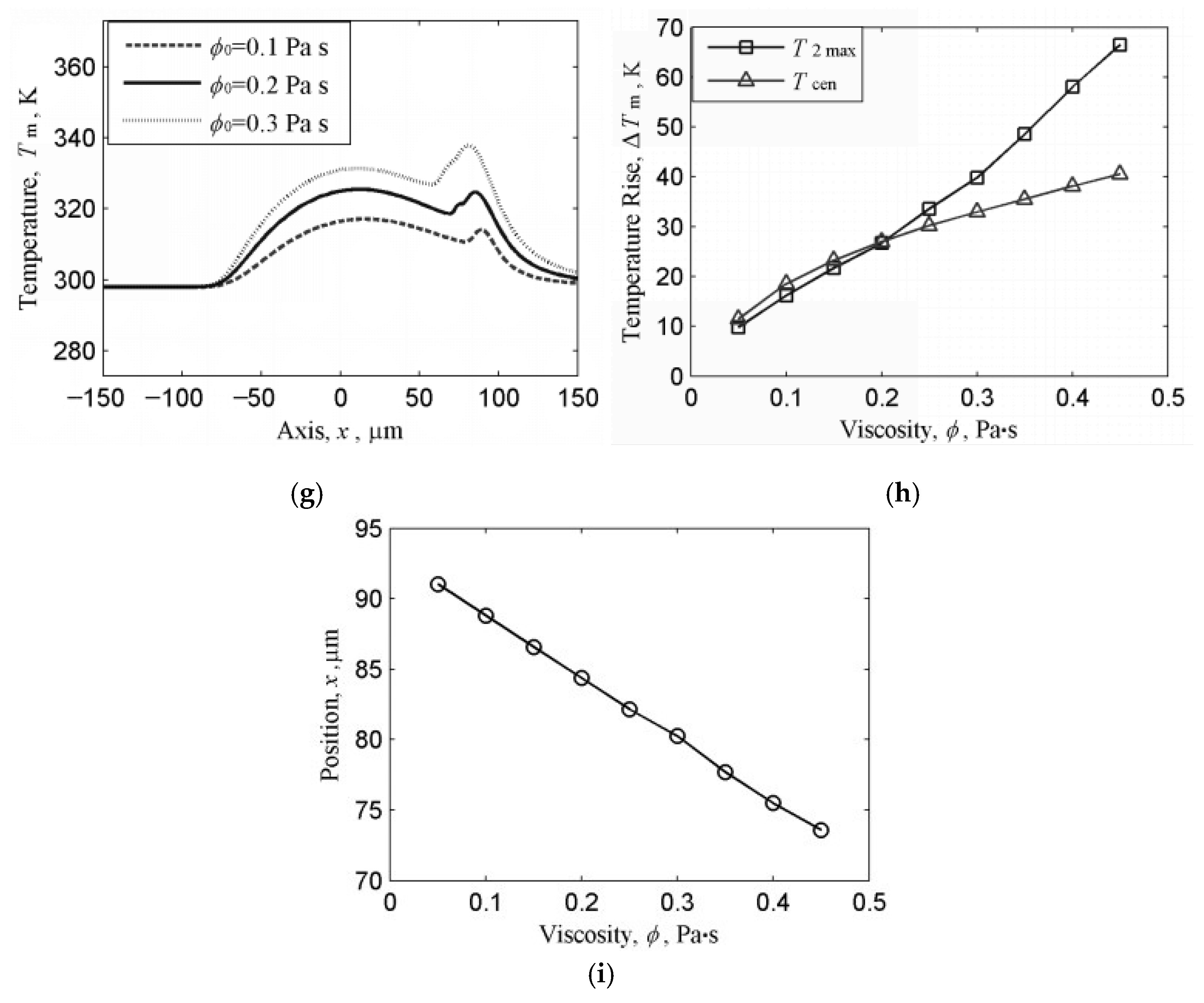
Figure 5 illustrates the effects of the initial grease viscosity on the thickness, pressure, and temperature of the lubricating film. As shown in Figure 5a, the thickness of the film increases with the increase in initial grease viscosity. Figure 5b illustrates that both central and minimum film thicknesses increase with an increase in viscosity, with the central film thickness showing stronger nonlinear growth than the minimum film thickness, which shows a gradual rise. Figure 5d,e indicate that the amplitude of the secondary pressure peak intensifies significantly with an increase in viscosity, while the central pressure decreases to maintain load equilibrium. As shown in Figure 5g, a higher initial viscosity enhances viscous heating, resulting in localized temperature spikes at the secondary pressure peak, whereas the central temperature rise remains smoother. Figure 5c,f,i collectively demonstrate that with an increasing viscosity, the positions of the minimum film thickness, secondary pressure peak, and secondary temperature peak shift toward the inlet zone. The secondary pressure and temperature peaks align spatially due to pressure-driven viscous dissipation. The minimum film thickness remains in the exit zone but lags behind the pressure/temperature peaks. The spatial alignment of the pressure and temperature peaks can be attributed to pressure-enhanced viscous dissipation at the maximum shear-rate region. The spatial decoupling between pressure and temperature peaks confirms distinct governing mechanisms: pressure peaks arise from inlet squeezing effects, while temperature peaks are driven by shear heating in maximum-shear-rate zones. The viscosity-dependent changes in film thickness and pressure distribution have a direct impact on the lubrication characteristics of the coupling. For high-viscosity grease, the inlet-shifted pressure peak may accelerate surface fatigue near the contact entry, while the thickened film enhances wear protection. Engineers must balance these effects by selecting appropriate lubricants to stabilize film thickness without inducing excessive viscous heating.
Three types of commercial lithium-based grease for automotive couplings (Table 1) were employed to investigate their effects on the lubrication performance of the TSUC. The properties of lubricating greases 1, 2, and 3 were evaluated at 298 K (25 °C).
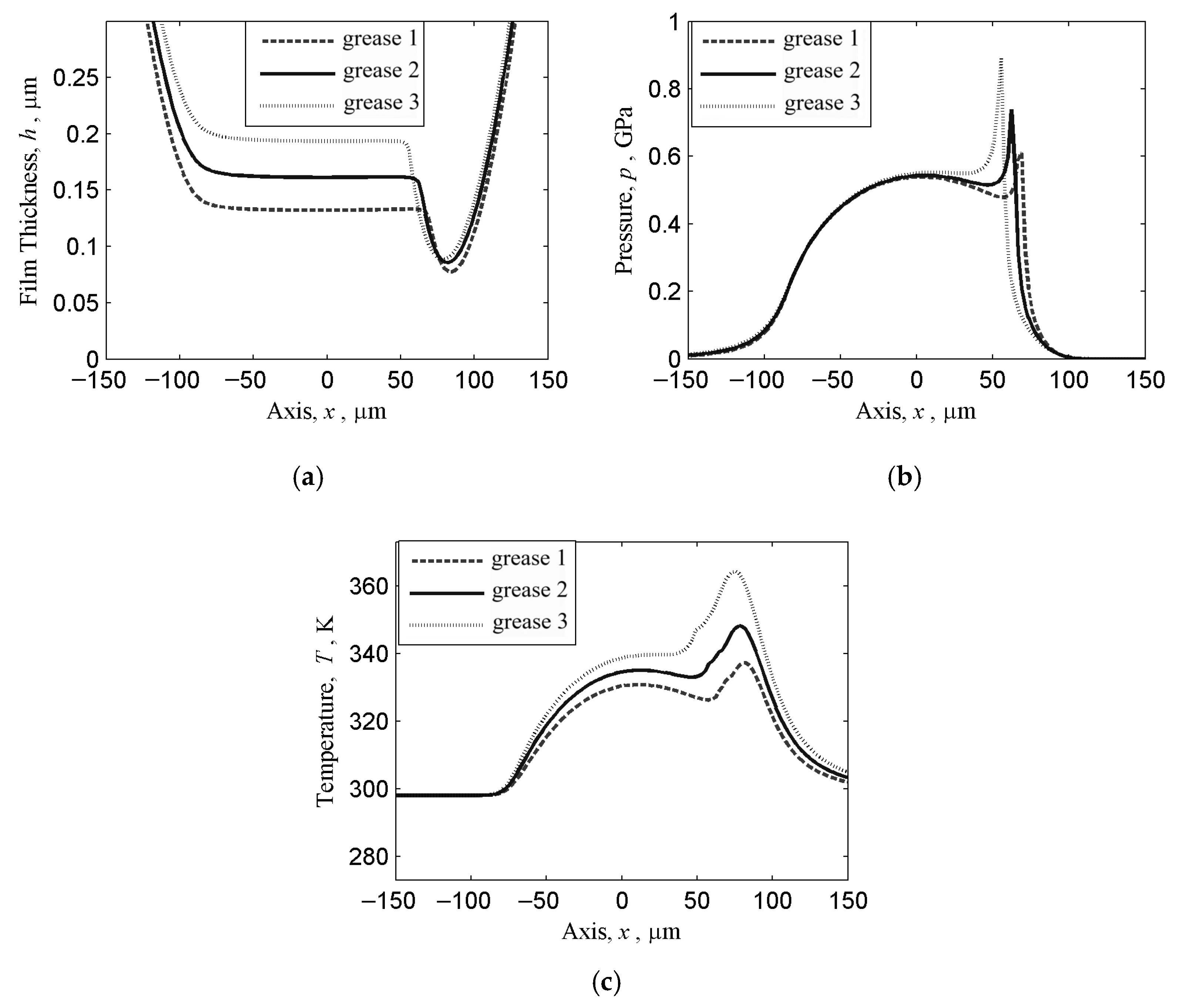
Figure 6 illustrates the influence of different types of grease on the pressure distribution and temperature profile of the lubricant film as well as film thickness. The film thicknesses generated by the three types of grease differ significantly. Figure 6a shows that when lubricating grease 1—with the lowest initial viscosity—is used, the film remains relatively thin. Additionally, the minimum film thickness and central film thickness are lower than the others, and the position of minimum film thickness is closer to the exit zone (Table 2). Figure 6b shows that the maximum values of the secondary pressure peak exhibit significant variations, while the central pressure decreases to maintain load equilibrium. When lubricating grease 1 is utilized, the maximum value of the secondary pressure peak is lower, and the location of this peak is comparatively backward, as shown in Table 3. Based on the analysis of Figure 6c, the use of lubricating grease 1 (with the lowest initial viscosity) results in a lower lubricating film temperature compared to other greases. This temperature reduction primarily stems from the lower viscous shearing and reduced internal friction within the thinner fluid film, which directly diminishes heat generation. Additionally, the secondary temperature peak is suppressed at both the center and secondary peak positions (Table 4), and its location shifts forward relative to greases 2 and 3. These trends align with the initial viscosity differences among the greases. Since the pressure–viscosity coefficients and densities (Table 1) are similar across greases, the initial grease viscosity emerges as the dominant governing parameter for film thickness, pressure distribution, and temperature profiles.
A higher grease flow index facilitates the formation of thicker lubricating films, thereby enhancing TSUC lubrication performance. However, elevated secondary pressure peaks can compromise the effectiveness of lubrication. Greater grease viscosity improves film thickness, making high-viscosity grease preferable under heavy-load conditions. Nevertheless, such types of grease may exacerbate secondary pressure peaks, shortening TSUC operational longevity and increasing power losses. When the pressure–viscosity coefficients and densities of different types of grease are nearly identical, the initial viscosity and thickener microstructure become critical determinants. Consequently, viscosity optimization must be prioritized.

4. Conclusions

(1)
Increasing the grease flow index enhances central and minimum film thicknesses by improving flowability. However, this elevates the amplitude of the secondary pressure peak, intensifying cyclic stress loading at the contact entry zone and promoting the propagation of surface fatigue. Future research should explore adaptive flow index control mechanisms to balance film thickness enhancement and stress oscillation suppression.
(2)
An elevated initial viscosity increases film thickness but amplifies viscous dissipation, leading to higher temperature distributions and power losses. This also shifts the secondary pressure peak toward the inlet, as the result of a delayed compressibility response in the fluid. Future studies should quantify viscosity–temperature thresholds for optimal film stability under dynamic loading conditions.
(3)
When three distinct types of grease were applied to the coupling, their lubrication properties diverged significantly. When different types of grease share similar pressure–viscosity coefficients and densities, the dominant performance factor shifts to their initial viscosity. Advanced machine learning models should be developed to predict such viscosity-dominated performance divergence in multi-grease systems.

Author Contributions

Conceptualization, D.C.; writing—original draft preparation, X.C. and Y.Z.; writing—review and editing, X.X. and C.D. All authors have read and agreed to the published version of the manuscript.

Funding

This research received no external funding.

Conflicts of Interest

The authors declare no conflict of interest.

Notation

AAmplitude, m
cGrease specific heat, J·kg−1·K−1
c1Upper surface specific heat, J·kg−1·K−1
c2Lower surface specific heat, J·kg−1·K−1
E′Effective Young’s modulus, Pa
fFrequency, Hz
hGrease film thickness, m
h0Rigid body displacement, m
kGrease thermal conductivity, W·m−1·K−1
k1Upper surface thermal conductivity, W·m−1·K−1
k2Lower surface thermal conductivity, W·m−1·K−1
nGrease flow index
pHydrodynamic pressure, Pa
REffective radius, m
sSlide-to-roll ratio
tTime, s
TTemperature, K
T0Initial grease temperature, K
uSurface velocity, m·s−1
u1Upper surface velocity, m·s−1
u2Lower surface velocity, m·s−1
xHorizontal coordinate, m
x0Inlet coordinate, m
xeOutlet coordinate, m
αViscosity-pressure coefficient, Pa−1
wLoad per unit length, N·m−1
ωAngular speed, ω = 2π f, rad·s−1
φGrease base oil viscosity, Pa·s
φ0Initial base oil viscosity, Pa·s
ρGrease density, kg·m−3
ρ0Initial grease density, kg·m−3
ρ1Upper surface density, kg·m−3
ρ2Lower surface density, kg·m−3

References

  1. Wang, X.F.; Chang, D.G. Numerical analysis on lubricating properties of tripod sliding universal couplings. Tribol. Trans. 2009, 52, 86–95. [Google Scholar] [CrossRef]
  2. Sadeghi, F.; Sui, P.C. Thermal elastohydrodynamic lubrication of rolling/sliding contacts. J. Tribol-T. ASME 1990, 112, 189–195. [Google Scholar] [CrossRef]
  3. Yoo, J.G.; Kim, K.W. Numerical analysis of grease thermal elastohydrodynamic lubrication problems using the Herschel-Bulkley model. Tribol. Int. 1997, 30, 401–408. [Google Scholar] [CrossRef]
  4. Kaneta, M.; Ogata, T.; Takubo, Y.; Naka, M. Effects of a thickener structure on grease elastohydrodynamic lubrication films. Proc. Inst. Mech. Eng. Part J J. Eng. Tribol. 2000, 214, 327–336. [Google Scholar] [CrossRef]
  5. Wang, J.; Kaneta, M.; Yang, P. Numerical analysis of TEHL line contact problem under reciprocating motion. Tribol. Int. 2005, 38, 165–178. [Google Scholar] [CrossRef]
  6. Yu, M.; Huang, P. Numerical analysis on thermal elastohydrodynamic grease lubrication in line contacts. Bearing 2011, 1, 8–12. [Google Scholar] [CrossRef]
  7. Wang, X.F.; Chang, D.G. Lubricating behavior of tripod sliding universal couplings. Ind. Lubr. Tribol. 2020, 62, 16–25. [Google Scholar] [CrossRef]
  8. Chang, D.G.; Wang, X.F.; Yang, F.Q.; Wang, J.Z. Lubricating properties of tripod sliding universal couplings considering thermal effect. Tribol. Trans. 2010, 53, 502–510. [Google Scholar] [CrossRef]
  9. Wang, X.F.; Hu, R.F.; Wang, K.S.; Cui, H.R. Effects of reciprocating motion parameters on lubricating properties of tripod sliding universal couplings. Ind. Lubr. Tribol. 2014, 66, 111–123. [Google Scholar] [CrossRef]
  10. Yang, F.Q.; Han, X.J.; Si, M.Q. Thermal elastohydrodynamic lubrication characteristics and optimisation of the ball-type tripod universal joint. Ind. Lubr. Tribol. 2021, 10, 1310–1318. [Google Scholar] [CrossRef]
  11. Yang, F.Q.; Xiao, Q.H.; Geng, C.H. Effect of surface micro-groove texture on lubrication performance of tripod universal coupling. Ind. Lubr. Tribol. 2021, 10, 1237–1247. [Google Scholar] [CrossRef]
  12. Laura, R.; Silvia, R.; Georg, J. Influence of temperature on wear performance of greases in rolling bearings. Ind. Lubr. Tribol. 2021, 73, 862–871. [Google Scholar] [CrossRef]
  13. Wang, L.L.; Zhang, W.; Zhao, X.T.; Ge, X. Optimization lubrication performance of journal bearings with microtexture. Ind. Lubr. Tribol. 2022, 74, 619–628. [Google Scholar] [CrossRef]
  14. Wang, W.Z.; Jin, Z.M.; Dowson, D.; Hu, Y.Z. A study of the effect of model geometry and lubricant rheology upon the elastohydrodynamic lubrication performance of metal-on-metal hip joints. Proc. Inst. Mech. Eng. Part J J. Eng. Tribol. 2008, 222, 493–501. [Google Scholar] [CrossRef]
  15. Ohno, N.; Yamada, S. Effect of high-pressure rheology of lubricants upon entrapped oil film behaviour at halting elastohydrodynamic lubrication. Proc. Inst. Mech. Eng. Part J J. Eng. Tribol. 2007, 221, 279–285. [Google Scholar] [CrossRef]
  16. Lin, J.R.; Teng, M.Y.; Ho, M.H. Effects of non-newtonian rheology on the film-height history between non-parallel sliding-squeezing surfaces. Proc. Inst. Mech. Eng. Part J J. Eng. Tribol. 2007, 221, 155–159. [Google Scholar] [CrossRef]
  17. Bair, S. Rheology and high-pressure models for quantitative elastohydrodynamics. Proc. Inst. Mech. Eng. Part J J. Eng. Tribol. 2009, 223, 617–628. [Google Scholar] [CrossRef]
  18. Karthikeyan, B.K.; Teodorescu, M.; Rahnejat, H.; Rothberg, S.J. Thermoelastohydrodynamics of grease-lubricated concentrated point contacts. Proc. Inst. Mech. Eng. Part J. 2009, 224, 683–895. [Google Scholar] [CrossRef]
  19. Huang, P. Numerical Calculation Methods of Elastohydrodynamic Lubrication; Tsinghua University Press: Beijing, China, 2013. [Google Scholar]
  20. Mo, H.; Hu, Y.; Quan, S. Thermo-Hydrodynamic Lubrication Analysis of Slipper Pair Considering Wear Profile. Lubricants 2023, 11, 190. [Google Scholar] [CrossRef]
  21. Wang, H.; Li, H.; Jin, Z.; Lin, J.; Cui, Y.; Li, C.; Tian, H.; Wang, Z. Simulation Analysis and Experimental Study on the Fluid–Solid–Thermal Coupling of Traction Motor Bearings. Lubricants 2024, 12, 144. [Google Scholar] [CrossRef]
  22. Deng, H.; Guo, B.; Huang, Z.; Xu, P.; Zhu, P. Thermal–Elastohydrodynamic Lubrication Characteristics of the Flow Distribution Pair of Balanced Double-Row Axial Piston Pumps. Lubricants 2024, 12, 342. [Google Scholar] [CrossRef]
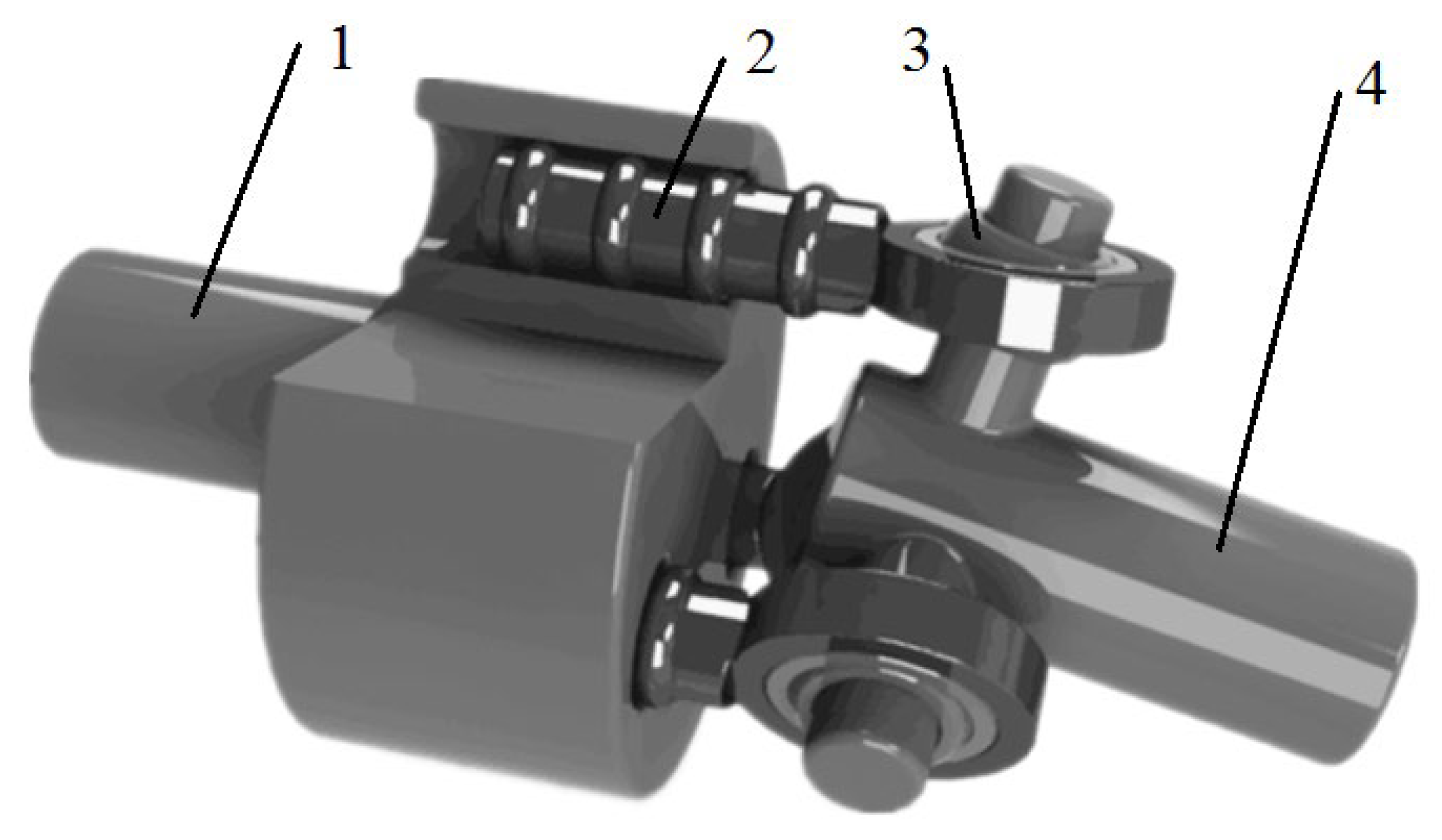
Figure 1. Schematic of the novel tripod sliding universal coupling: (1) tripod sleeve; (2) sliding rod; (3) coupling bearing; and (4) tripod shaft.
Lubricants 13 00400 g001
Figure 2. Cross-section of the anti-wear structure at the sliding rod–tripod sleeve interface.
Lubricants 13 00400 g002
Figure 3. Simplified geometric model.
Lubricants 13 00400 g003
Figure 4. The effect of the grease flow index on lubricating film characteristics at the midpoint of the stroke, with ϕ0 = 0.289 Pa·s, R = 10 mm, and w = 80 kN/m: (a) film thickness profile, (b) minimum and central film thicknesses, (c) position of minimum film thickness, (d) pressure distribution, (e) central pressure and secondary peak pressure value, and (f) the position of the secondary pressure peak.
Lubricants 13 00400 g004aLubricants 13 00400 g004b
Figure 5. The effect of initial grease viscosity on lubricating film characteristics at the midpoint of the stroke, with n = 0.9, R = 10 mm, and w = 80 kN/m: (a) film thickness profile, (b) minimum and central film thicknesses, (c) position of minimum film thickness, (d) pressure distribution, (e) central pressure and secondary peak pressure values, (f) position of the secondary pressure peak, (g) temperature distribution, (h) central temperature and secondary temperature peak rise, and (i) position of the secondary temperature peak.
Lubricants 13 00400 g005aLubricants 13 00400 g005b
Figure 6. The effect of grease type on lubricating film characteristics at the midpoint of the stroke, with n = 0.9, f = 30 Hz, A = 1 mm, R = 10 mm, and w = 80 kN/m: (a) film thickness profile, (b) pressure distribution, and (c) lubricating film temperature distribution.
Lubricants 13 00400 g006
Table 1. Grease properties at 298 K.
Greaseϕ0 (Pa·s)α (m2/N)ρ0 (kg/m3)
Lubricating grease 10.2892.923 × 10−8889.2
Lubricating grease 20.3703.009 × 10−8918.2
Lubricating grease 30.4513.077 × 10−8897.8
Table 2. Effect of grease formulations on central-stroke film thickness.
GreaseCentral Film Thickness (µm)Minimum Film Thickness (µm)The Position of Minimum Film Thickness (µm)
Lubricating grease 10.13230.077484.367
Lubricating grease 20.16130.085782.150
Lubricating grease 30.21580.088577.707
Table 3. Effect of grease formulations on central-stroke pressure.
GreaseCentral Pressure (GPa)Secondary Peak Pressure (GPa)The Position of the Secondary Pressure Peak (µm)
Lubricating grease 10.53860.611468.831
Lubricating grease 20.54260.738462.171
Lubricating grease 30.55030.893955.502
Table 4. Effect of grease formulations on lubricating film temperature rise at the midpoint of the stroke.
GreaseCentral Temperature Rise (K)Temperature Rise in Secondary Temperature Peak (K)The Position of Secondary Temperature Peak (µm)
Lubricating grease 132.302639.195882.150
Lubricating grease 236.488150.074977.707
Lubricating grease 346.608366.249475.490
Disclaimer/Publisher’s Note: The statements, opinions and data contained in all publications are solely those of the individual author(s) and contributor(s) and not of MDPI and/or the editor(s). MDPI and/or the editor(s) disclaim responsibility for any injury to people or property resulting from any ideas, methods, instructions or products referred to in the content.