Review

A Comprehensive Review of Safety Tire Research

1
School of Traffic Engineering, Nanjing Institute of Technology, Nanjing 211167, China
2
National Key Laboratory of Automotive Chassis Integration and Bionics, Changchun 130015, China
3
College of Energy and Power Engineering, Nanjing University of Aeronautics and Astronautics, Nanjing 210016, China
4
College of Mechanical Engineering, Yangzhou University, Yangzhou 225127, China
*
Author to whom correspondence should be addressed.
Lubricants 2025, 13(8), 357; https://doi.org/10.3390/lubricants13080357
Submission received: 24 June 2025 / Revised: 5 August 2025 / Accepted: 9 August 2025 / Published: 12 August 2025

Abstract

In frequent traffic accidents, the issue of vehicle losing control due to tire blowouts is particularly critical. Once it occurs, it severely threatens the safety of life and property. Therefore, developing safety tires that meet public needs is of significant practical importance. This paper first reviews the evolutionary history of safety tires, classifying them by structural design and detailing the characteristics of run-flat tires (RFTs) and non-pneumatic tires (NPTs). It summarizes the key experimental characterization, numerical simulation and theoretical modeling methods that support their development, while also emphasizing the insufficiency in experimental verification. Next, the research advancements in materials and manufacturing processes for key components across these two tire categories are summarized. Subsequently, a review is provided on the mechanical characteristics of RFTs and NPTs. Finally, this paper discusses existing research gaps and future development directions for safety tires, emphasizing the importance of multi-disciplinary integration and sustainable design.

1. Introduction

The automobile industry is developing rapidly, and people’s attention to traffic safety increases. Tires—the only part of the vehicle in contact with the ground—play an important role in the mobility, safety and comfort of the vehicle. Therefore, their safety and reliability have attracted much attention. In China, 46% of highway traffic accidents are caused by tire faults, with tire blowouts constituting 70% of these incidents [1].
On the one hand, the occurrence of tire accidents is closely related to the tires them-selves. Traditional pneumatic tires rely on the air pressure in the inner cavity to support the weight of the vehicle, which has inherent safety hazards. Abnormal tire pressure can easily lead to increased tread wear, overheating of the carcass and even tire blowouts. After losing pressure, the vehicle’s maneuverability plummets, which can easily result in major accidents. Drozd et al. [2] studied the collision accident between truck and passenger car, revealing a deeper issue: tire rupture caused by material coating delamination and steel cord corrosion. The resulting tire deflation will cause the vehicle to lose control instantly. The unpredictability of such loss of control often leaves drivers insufficient reaction time, eventually resulting in a collision. On the other hand, the accident is due to the contact characteristics of the tire and the road surface. The friction loss of the tire under complex road conditions and the continuous tire–road interaction during long-term driving aggravate the decrease in air tightness. In this regard, Jilek et al. [3] upgraded the dynamic adhesion instrument (DA) through hydraulic control, which can achieve online dynamic adjustment of wheel position. It improves the simulation ability of the equipment under complex working conditions and makes DA a key tool for studying the contact characteristics between tire and road surface. It also provides an experimental basis for quantifying the contact failure parameters. These factors mentioned above, along with the maintenance costs, have driven the safety tire technology to become the focus of industry research and development.
The development process of safety tires can be traced back to the beginning of the 20th century. The United States Goodyear Company first proposed and obtained the patent for the explosion-proof inner tube in 1934. In 1955, the double-chamber safety tire was introduced, and the insert-supporting run-flat tires (ISRFTs) were mass-produced in the middle and late 20th century. In 1973, Goodyear also proposed the self-supporting run-flat tire (SSRFT), which was mass-produced and loaded in 1994. In 1926, the U.S. Hutchinson Company provided an inserts body system for RFT for military vehicles. In 1997, Michelin introduced the MXV RFT, and in 1998, the PAX ISRFT was introduced for civil vehicles [4]. In 2002, Bridgestone Co., Ltd. partnered with German and Japanese enterprises to develop the inserts body, ring-type, run-flat system ‘Bridgestone Support Ring’ and released the third generation of self-supporting products in 2009. In recent years, the German Continental Group has also developed intelligent ISRFTs. The research on safety tires in China started relatively later. In the middle of the 20th century, Shenyang T-Rubber, Shuguang Rubber and other enterprises took the lead in research and development and realized the production of various types of RFTs [5]. Tianyi Tire, Guizhou Tire and other enterprises also launched special products. In the past two decades, China has increased investment in scientific research, focused on the improvement of tire structure and materials, and promoted the rapid development of the industry.
According to the relevant research on safety tires at home and abroad, tire safety technology can be divided into run-flat technology and non-pneumatic technology [6]. At present, most of the RFTs are mainly ISRFTs and SSRFTs. Some scholars have carried out theoretical research on the inserts-supporting types. They proposed design criteria and established models to provide theoretical basis for the design of the inserts body structure [7]. Although the sidewall hardening design of the SSRFT improves its supporting capacity, it also leads to increased noise, decreased comfort, high cost and difficulty in maintenance and replacement. Although the RFT can alleviate the risk of tire blowouts to a certain extent, it cannot fundamentally eliminate the hidden danger of tire blowouts. Therefore, the research on NPT has become an inevitable development trend.
NPT replaces the inflation pressure of the tire with an elastic supporting structure. The integrated tire–rim design is adopted. The vibration is reduced and the ground bump energy is absorbed by the deformation of the rim and the elastic spoke. The concept was first proposed by the American engineer Brian Russell and was initially applied to mountain bike tires. In 2005, Michelin introduced the Tweel NPT (Figure 1a), while the U.S. company Cooper Tire subsequently launched a honeycomb bionic tire (Figure 1b). In 2011, Bridgestone developed a radial spiral mesh NPT (Figure 1c) and introduced the second generation of NPT in 2013 (Figure 1d). In 2014, the BAIC Group launched a negative Poisson’s ratio NPT (Figure 1e), using a negative Poisson’s ratio microstructure material to improve impact resistance. In 2010s, Hankook launched the I-Flex tire (Figure 1f), which employed polyurethane material and irregular honeycomb structure to improve bearing capacity and elasticity; It unveiled the airless ‘I-Flex’ concept in 2015 (Figure 1g). In 2017, Goodyear developed thermoplastic NPTs using thermoplastic materials to simplify the production process. In addition, Nanjing University of Aeronautics and Astronautics developed the ‘mechanical elastic wheel (ME-wheel)’ using hinge-structure support to study its static stiffness and cornering characteristics [4,8,9,10].
At present, with increasing research on NPTs, many scholars have conducted comprehensive reviews. Sun [11] et al. reviewed the materials used in NPTs, including tread, elastic support structure, skeleton and adhesive. They summarized a variety of manufacturing process and analyzed the current challenges and trends. Deng et al. [10] systematically introduced various types of representative tires and their characteristics in detail. They summarized research results on materials, mechanical characteristics and molding process. In addition, they proposed the idea of applying intelligent materials and structures to NPTs, along with future development trends. Sardinha et al. [12] reviewed research on the structural characteristics and mechanical characteristics of NPTs. The related standards, analysis strategies, materials, production technology and tire service life were discussed as well.
In summary, as an important technical solution for addressing the safety hazards of traditional pneumatic tires, both RFTs and NPTs have achieved significant research progress. However, there is currently a lack of comprehensive review of the research on RFTs. In this paper, the structural design, material selection and mechanical characteristics of these two types of safety tires are comprehensively reviewed. The research status and existing problems are deeply analyzed, and, combined with the development trend of the industry, the future development direction is prospected. Section 2 systematically categorizes the classification system of safety tires and summarizes the research progress of typical structural forms. Section 3 reviews the material design of safety tires and the cross-integration of multi-materials and manufacturing processes. Section 4 summarizes the research results of the mechanical characteristics of safety tires. Section 5 discusses future development trends and proposes potential paths for performance breakthroughs.

2. Classification of Safety Tires

The classification of safety tires is shown in Figure 2. Safety tires can be divided into RFTs and NPTs. Common RFT designs include insert-supporting types, self-supporting types and self-sealing types. NPTs are classified by the structure of their supporting bodies, with common types including the spoke-type, porous-structure and ME-wheel designs. This chapter mainly summarizes the research progress of the ISRFT and the SSRFT, the porous-structure and spoke-structure of the NPTs and the structure of the ME wheels.

2.1. Structural Design of RFTs

The core of run-flat technology lies in a special structural design. Their inserts body structures enable pneumatic tires to continue supporting the vehicle for a limited distance after pressure loss. ISRFT and SSRFT are the mainstream research directions for RFTs.

2.1.1. Structural Design of ISRFTs

The ISRFT typically consists of a tire, inserts body structure, rim and tire pressure monitoring device. Its working principle is that the inserts body remains inactive under normal operating conditions. When the tire loses pressure, the inserts body bears the vehicle’s weight and prevents tire bead detaching.
In terms of structural design, rims can be divided into standard or non-standard, and radial tires are predominantly used. Yang et al. [13,14] employed 22.5 × 9.00 rims and 12R22.5 radial tires in their research to meet the high-load requirements of heavy vehicles. They also selected 6 J × 15 rims and 205/60R15 radial tires for related studies. This combination was likely used to explore the performance and design optimization of inserts body in RFTs under different vehicle types or working conditions. Zang et al. [15] selected 16 × 6.5 J type 5° deep groove rims and 205/55R16 radial tires. They focused on lightweight design and zero-pressure driving performance optimization for passenger vehicles.
The design parameters of the inserts structure need to comprehensively consider the relationship with the tire profile, deformation and assembly. The determination of parameters such as inner diameter, outer diameter, section height and width are included as well. Some research also focuses on the heat dissipation and weight-reduction design of the inserts. Zang et al. [15] proposed the combined ISRFT structure, as shown in Figure 3. This structure adopted the standard rim design, added a heat dissipation groove to the outer surface of the inserts and designed the weight reduction groove on both sides. Its advantages are a simplified structure and reduced costs. Traditional inserts had problems such as large weight and large moment of inertia. Zang et al. [16] improved the overall performance of tire by topology optimization of the tire inserts body structure. They have achieved the goals of weight reduction, bearing performance optimization and design accuracy improvement. Liu et al. [17] studied different rubber formulations and structures. They focus on optimizing the inserts body performance, solving many problems during zero-pressure driving conditions and improving the overall performance and safety of tires.
In studying the design and research methods of the inserts body structure of tires, many scholars have explored the subject from different angles. They provide a variety of technical means and theoretical basis for the development of ISRFTs, including virtualization design, machine learning algorithms and interdisciplinary modeling. Yang et al. [13] utilized the adaptive function of Autodesk Inventor in the design process of parts under constrained conditions. This allowed the temporary existence of under-constrained geometric primitives. When the assembly conditions of parts changed, the corresponding features of parts were automatically adjusted to meet the new assembly conditions. With the AIP design environment, the weak parts of the inserts body and weight-loss components were modified to create a virtual assembly for model validation [14]. At the same time, to guide the design of inserts body structures, they established a zero-pressure rolling spring-damping model and a zero-pressure walking brush model [18]. During the design and optimization of inserts body structures, Zang et al. [16] employed topology optimization theory using the variable density method during the design and optimization of inserts body structures, effectively addressing issues in traditional inserts body and enhancing tire performance. These research outcomes had significantly advanced the field of ISRFT and laid a solid foundation for improving vehicle driving safety.
At present, significant progress has been made in the structural research of ISRFT in rim adaptation, topology optimization and heat dissipation weight reduction design. Research approaches in this field have also become increasingly diverse. However, the existing research optimization objectives are mostly focused on static or single performance. The multi-objective collaborative optimization and long-term durability verification under dynamic conditions are insufficient. In addition, the research on the manufacturability design and low-cost mass production process adaptability of complex, innovative topologies still falls behind. Such complex structures include deep groove rims and gradient hollow structures.

2.1.2. Structural Design of SSRFT

The SSRFT is primarily composed of a tire body, sidewall insert rubber (SIR), rim and tire pressure monitoring device, as shown in Figure 4. This tire operates on the principle of its special structural design: under normal driving conditions, the tire’s internal pressure remains sufficient. The SIR works in conjunction with other components to maintain the tire’s normal geometry, ensuring driving performance comparable to ordinary tires. In the event of a puncture, or when inflation pressure drops below a critical threshold, the internal pressure can no longer provide adequate support. The SIR, with its high rigidity, then bears the vehicle’s weight, effectively preventing excessive sidewall deformation and self-fold-over. It enables the tire to retain its shape and load-bearing capacity under run-flat conditions.
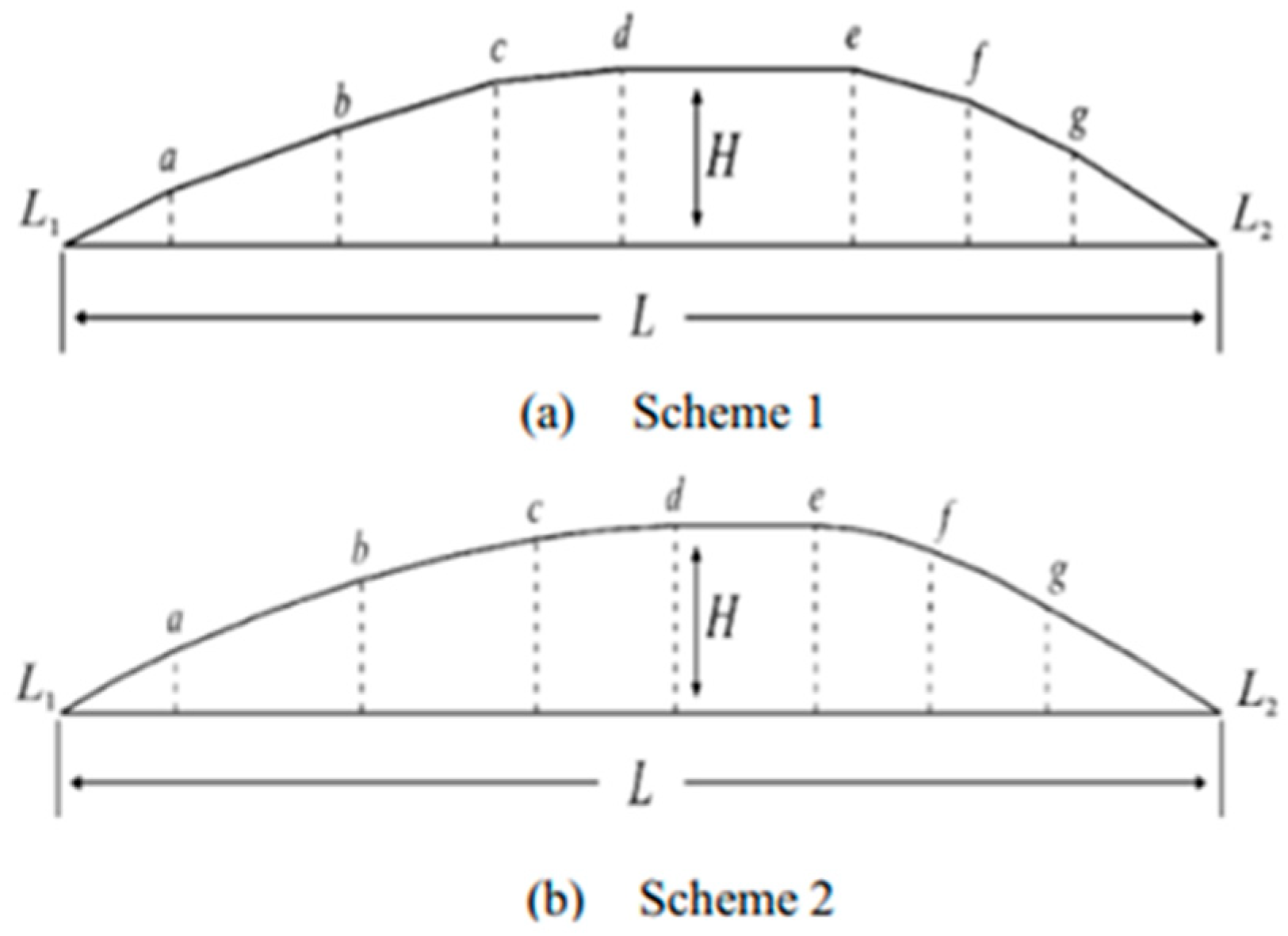
The main body of the tire usually adopts a radial tire structure to provide basic load-bearing and rolling functions. SIR is the key component of SSRFT. In the existing research, researchers used the geometric elements of the SIR as the core design variables and designed structural topology innovation or parameter optimization. In this way, the performance of the tire under zero-pressure and normal driving conditions is improved. To optimize sidewall inserts rubber in RFTs, Cho et al. [19] proposed a generalized multi-objective optimization method based on a genetic algorithm, with the SIR illustrated in Figure 5c as the optimization target. Differing from the ring types in Figure 5a,b, the sidewall-reinforcement type enhances sidewall stiffness to prevent collapse when the tire blowouts. The regions below the red line in Figure 5c respectively indicate the collapse degree of conventional tires and SSRFT after a blowout. This method was used to optimize the shape and stiffness of sidewall inserts. Specifically, it replaced time-consuming finite element analysis (FEA) with genetic evolution and integrated neural network technologies for research. On the basis of the 225/50 R17 98W radial tire, Lv et al. [20] added the design of insert rubber with hard texture on the sidewall. The outer side of the SIR was close to the inner wall of the sidewall deflection area in a crescent shape. Its upper and lower ends extended to the shoulder and bead area, respectively. Meanwhile, the inner side was close to the reinforced cord layer, which improved the sidewall strength. Lv et al. [21] studied the design parameters of the SIR, as shown in Figure 6. The maximum width L and the maximum thickness H affect the stiffness and contact characteristics of the tire. The change of L affects the overlap area of the SIR with the tread and the belt, which affects the bearing and stress distribution of the tire. The change of H is directly related to the deformation position and stress of the SIR. In conclusion, the structure and parameter design of the SIR influence SSRFTs’ mechanical characteristics under zero-pressure and rated pressure conditions. The characteristics involve radial stiffness, ground stress distribution, tread stress, etc. It is an important factor to balance the driving comfort, handling and zero-pressure driving ability of the vehicle.
At present, the optimization of the geometric parameters of the SIR is mostly limited to the local sidewall area. There is a lack of collaborative design with the overall structure of the tire. Consequently, the problems of stress mutation in the shoulder and bead area under zero-pressure conditions have not been solved.
Moreover, whether it is ISRFT or SSRFT, the flexibility of the tire belt and carcass plays a significant role in tire–road contact characteristics. Specifically, the tire belt layer lies between the inner belt layer and the carcass ply, shouldering 60% to 75% of the tire’s stress [22]. To further explore the mechanisms behind these effects, researchers have proposed relevant research with different models. Among them, as a well-known flexible tire model, the flexible ring tire (FTire) model, can accurately simulate how the belt layer affects the tire dynamic forces and is widely used in ride comfort, handling and road load prediction. Its mechanical model is subdivided into sub-models for the belt–layer–carcass–bead structure and sub-models for tread mechanical and tribological characteristics [23]. George et al. [24] developed a tire model to analyze the transient handling performance of a tire. The model couples the flexible carcass–belt structure with the tread. Distinctive from other existing models, it achieves a purely dynamic representation of tire–road contact interactions. It can consider the viscoelastic and inertial properties of separate discretized tread, coupled with a generic stick–slip friction law. Yamashita et al. [25] devised a physics-based flexible tire model. This model can be used to analyze the transient braking and cornering characteristics of tires. It integrates the distributed parameter LuGre tire friction model with the flexible tire model. It can predict transient shear contact stress through spatial discretization. The model can consider the dynamic coupling between tire structural deformation and transient tire friction behavior, thus addressing the issue that traditional steady-state models fail to capture history-dependent dynamic friction effects.
In summary, through the structural topology optimization of the inserts, heat dissipation and weight reduction effects can be achieved. Optimizing the structure of the SIR of the SSRFT can improve the vehicle’s performance under zero-pressure conditions. Additionally, based on these flexible models mentioned above, future research can focus on the optimal design of the tire to improve contact performance under transient conditions, thereby enhancing vehicle handling safety.

2.2. Structural Design of NPT

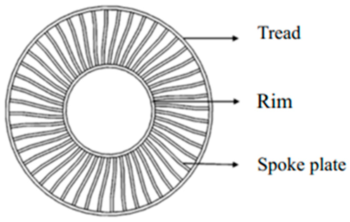
The structure of NPT is simpler than that of a conventional pneumatic tire and is composed of three components, including a tread, a rim and a supporting structure, as illustrated in Figure 7. Rather than adopting the traditional airtight cavity structure of pneumatic tires, the elastic support structure is utilized to substitute for the inflation pressure of the tire. This feature enables the tire to function. Through specialized mechanical design, the bearing, shock-absorption and rolling functions are achieved. Furthermore, the risk of tire blowouts caused by abnormal tire pressure is avoided, which significantly enhances the safety of vehicle operation.
Currently, numerous scholars have conducted research on NPTs of different structural types. Among these types, the porous-structure type, the spoke-structure type and the ME wheels are predominant.

2.2.1. Structural Design of Porous-Structure NPT

At present, many companies have achieved remarkable results in the field of NPTs with a porous structure. The Polymer Research Center in Madison, Wisconsin, USA has invented a hexagonal honeycomb tire (Figure 8a). The tire adopts a regular hexagonal pore structure and belongs to a typical honeycomb design in porous structures. In 2017, Michelin launched a concept tire, a 3D-printed biodegradable Vision tire (Figure 8b), which mimics the grid-like bionic porous structure of the alveoli.
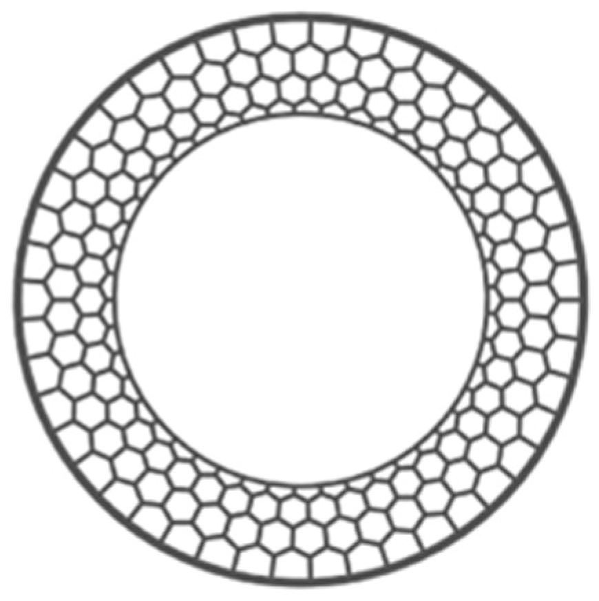
The honeycomb structure is essentially a regular hexagonal porous form. The honeycomb hexagonal support structure designed according to the honeycomb principle (as shown in Figure 9), enables even distribution of tire mass and has high bearing capacity. The honeycomb unit transmits load and absorbs energy. By optimizing the configuration of the pneumatic tire cord layer, the honeycomb composite wheels can reduce the local damage and improve the impact resistance [26]. This structure is suitable for off-road vehicles, military applications and heavy machinery.
Many scholars have carried out extensive research on honeycomb structure NPTs. Jin et al. [27] analyzed three kinds of honeycomb spoke NPTs with the same hole wall thickness and bearing capacity through numerical simulation. They studied the influence of different geometric parameters on static and dynamic characteristics. Ganniari et al. [28] studied the mechanical behavior of honeycomb nanotubes and the influence of geometric parameters on the mechanics of NPTs by numerical analysis. Zheng et al. [29] used the Taguchi method to design different parameter combinations. Then, they evaluated the influence of each design parameter on the multiaxial stiffness and road contact characteristics of honeycomb tires. The method provided more accurate theoretical guidance for the design of honeycomb NPTs.
In recent years, in order to break through the performance limitations of traditional honeycomb structures, researchers have focused on the innovative design of irregular structural forms. Zhao et al. [30] proposed an innovative negative Poisson‘s ratio NPT support structure. It was composed of a unique three-layer concave quadrilateral microstructure and had significant “compression-shrinkage” negative Poisson’s ratio characteristics. The maximum stress was significantly reduced compared to the traditional hexagonal honeycomb NPT. Zang et al. [31] innovatively proposed a two-dimensional double U-shaped honeycomb structure based on negative Poisson’s ratio. They replaced the straight section of the traditional structure with the U-section of the cosine curve. This effectively reduced the sharp angle and achieved a smooth connection of the structure. Yang et al. [32] designed six kinds of thickness gradient honeycomb spokes. They then studied the influence of thickness gradient on the static and dynamic mechanical characteristics of NPTs. The results showed that the reasonable design of thickness gradient could significantly improve the bearing capacity and reduce the stress concentration.
The early research on NPTs with porous structures mainly focused on changing the geometric parameters of the honeycomb structure. The goal was to achieve the purpose of optimizing performance. In the later stage, it gradually transformed into active optimization. Through the innovative design of the structure, negative Poisson’s ratio and spherical porous structures were proposed. To meet the requirements of NPT performance improvement, many innovations have been put forward on honeycomb structures. However, the research is still not sufficiently in-depth. In the future, advanced numerical simulation technology can be used to deeply analyze the stress distribution of honeycomb structures in complex working conditions. At the same time, a multi-objective optimization algorithm can be employed to establish an accurate parameter optimization model combined with different scene requirements. The influence of various structural parameters on tire performance will be comprehensively explored.

2.2.2. Structural Design of Spoke-Structure NPT

The spoke structure type adopts a bionic spoke design, typically composed of a hub, spokes made of metal or high-strength composite materials and tread. Impact is absorbed through the elastic deformation of the spokes, while a rigid spoke system supports the vehicle’s weight. Spoke structures in NPTs exhibit various forms and distinct characteristics: The curved single spoke can flexibly adapt to local stress. Hexagonal honeycomb spokes can uniformly disperse pressure and have excellent bearing capacity. Polygonal honeycomb spokes can achieve higher vertical stiffness and weight ratio after optimization, which is conducive to the lightweight design of tires [33].
In 2005, Michelin first introduced Tweel, as shown in Figure 10a. The main structure includes a hub, polyurethane (PU) spokes, a shear band and a rubber tread. In 2015, Sumitomo Rubber Industries [10] introduced the innovative Gyroblade tire (Figure 10a), which has a unique supporting structure. Six pairs of leaf-shaped resin spokes are distributed along the rim circumference evenly. The structure can effectively disperse load pressure during driving and ensure uniform tire–road contact pressure. In 2019, Michelin launched the unique puncture-resistant tire system (UPTIS) tire (Figure 10a). It was composed of a rim, spokes, a reinforcing plate, a tread and inner and outer steel wire reinforcing layers.
In recent years, mechanical characteristics have become the main entry point for scholars studying spoke-structure NPTs. Rugsaj et al. [34] established a finite element model (FEM) of NPTs with different spoke shapes. The model, based on Michelin’s Tweel 12N16.5 SSL all-terrain tire (Figure 11a), was applied to investigate how spoke geometry affected maximum stiffness and minimum local stress. Fu et al. [35] proposed a novel NPT with a flexible-spoke structure. Specifically, they employed thermo-mechanical sequential coupling to analyze the tire’s thermo-mechanical coupling characteristics under various working conditions. Fu et al. [36] predicted the fatigue life of a mesh soft-spoke NPT and analyzed how structural parameters impact fatigue life. In the research, the J-integral energy release rate crack propagation method was used. Ku et al. [37] developed a three-dimensional numerical analysis model for a new flexible-spoke NPT. By combining tire steady-state rolling theory, they conducted simulations of steady-state mechanical characteristics under multiple conditions, obtaining corresponding characteristic curves and laws.
On the basis of research into basic spoke structures, some scholars have focused on innovative spoke design with bionics principles. Zhang et al. [38] designed a flexible-spoke bionic NPT. They were inspired by kangaroo hindlimb structures and then analyzed its mechanical characteristics under varying loads. Shuai et al. [39] proposed a V-spoke NPT (sample shown in Figure 11c), conducting simulations and tests to investigate how design parameters affect tire mechanics. Rugsaj et al. [40] developed an X-spoke NPT for military vehicles (Figure 11d), comparing its rolling characteristics and vertical stiffness.
In structural parameter studies, Liu et al. [41] designed spokes for a Fibonacci spiral NPT (FS-NPT). The design was based on its three-dimensional stiffness characteristics, analyzing how spoke thickness, initial Fibonacci spiral radius and spoke width influenced FS-NPT stiffness. Sun et al. [42] used Timoshenko beam theory to establish a mechanical model for composite-spoke NPTs. They employed response surface methodology to study correlations between key structural parameters and vertical stiffness. Ni et al. [43] proposed a new composite-spoke NPT structure. They investigated the relationship between tire sinkage and motion interference between adjacent support units under different double-circular-arc cross-section thicknesses. Notably, damaged support units can be individually replaced, reducing operational costs. Zhou et al. [44] studied how lateral spoke thickness affects radial and lateral stiffness in honeycomb NPTs. By varying spoke thickness, using Latin hypercube sampling to construct surrogate models and applying NSGA-II for multi-objective optimization, they achieved collaborative optimization of the two stiffness characteristics.
Initially, research on spoke-structured NPTs focused on the mechanical characteristics of basic spoke designs. Later, the focus shifted to structural parameter tuning and bionic-inspired spoke innovations.

2.2.3. Structural Design of ME Wheel

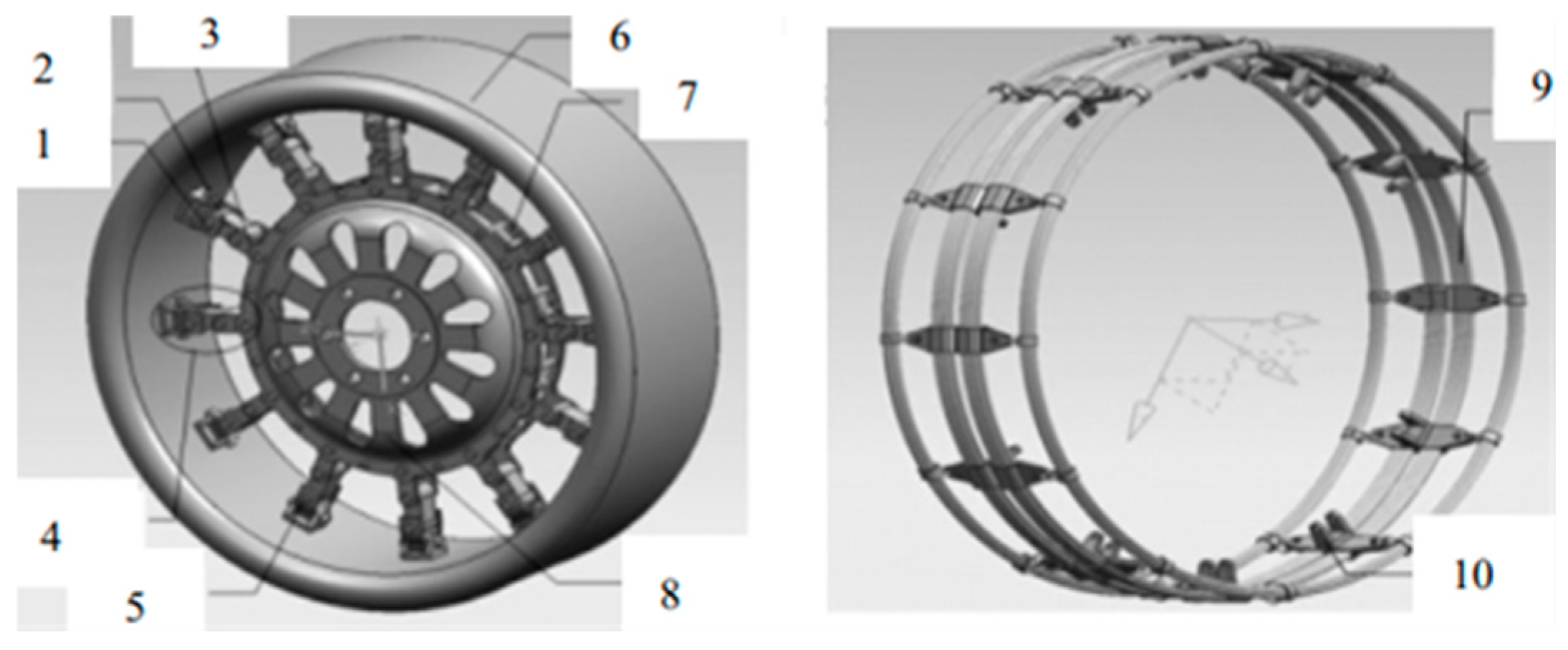
The research team of Professor Zhao Youqun from Nanjing University of Aeronautics and Astronautics proposed a design scheme. The scheme is a ME safety wheel with non-pneumatic structure, as shown in Figure 12. It is mainly composed of three parts: elastic wheel, hinge group and suspension hub. The mechanical structure elasticity is used to replace the rubber inflation elasticity of traditional pneumatic tires. On the basis of satisfying the necessary functions of pneumatic tires, it also has the characteristics of stab resistance, damage prevention and high bearing capacity. Its core innovation is to make the hub-type bearing structure and the elastic ring-hinge group collaboratively deform. This collaborative deformation mechanism can break through the pressure-dependent defects of traditional pneumatic tires. Furthermore, it can realize stable bearing and dynamic response under complex working conditions [4].
Wang et al. [45] proposed a new ME wheel for a certain wheeled special vehicle. As shown in Figure 13, the wheel is primarily composed of a driving rubber ring, elastic ring, elastic ring clip, hub, return spring, pin and hinge, etc. To address the issue of repetitive design when adjusting structural dimensions or checking the strength of ME wheels, Yan et al. [46] developed a ME-wheel design platform. Based on parametric design and the Pro/E secondary development theory, the platform enables automatic structural dimension checking, 3D model generation and virtual assembly. They carried out the mechanical analysis of the wheel structure to clarify the classification of important structural parameters. At the same time, they described the establishment method of the top-down parameter constraint relationship.
In order to reduce the weight of the ME wheel, Feng et al. [47] investigated the working conditions of the wheel under bending moment load and radial load. They established FEM and carried out the simulation analysis to determine the load of the hub and hinge group. They employed the weighted variable density method to optimize the topology of the hub and hinge group and reconstructed the three-dimensional model after optimization. The results showed that the quality of the optimized hub and hinge was reduced to a certain extent. Under the condition that the structure was the same as the actual wheel model, Jiang et al. [48] established the FEM of the ME wheel. They used FEM to achieve structural coordination between the wheel and the return function of the spring. The radial stiffness of the wheel was calculated by ANSYS software. The length of each section of the spoke was taken as the design variable. Moreover, he radial stiffness of the tire was taken as the optimization target. The sequential quadratic programming (SQP) algorithm was used to optimize the wheel structure.
In order to further optimize wheel performance, Li et al. [49] used the brush theory model to establish a simplified theoretical model of ME wheel steady-state cornering. Meanwhile, they analyzed the influence of structural parameters on the cornering characteristics of the ME wheel. The researchers established a nonlinear 3-degree-of-freedom (3-DOF) rollover prediction model of the whole vehicle matching the ME wheel. The study took the improved load transfer rate as the evaluation index of rollover stability. In addition, they studied the influence of wheel cornering mechanical characteristics on rollover stability. The results showed that the structural parameters of the hinge group had little effect on the cornering characteristics. Three changes could increase the wheel cornering stiffness and lateral force peak and improve the rollover stability of the vehicle equipped with ME wheels. The adjustments are as follows: appropriately increasing the distribution height of the elastic ring, reducing the aspect ratio of the elastic wheel section and reducing the initial shear modulus.
As the research deepened, the team also developed a series of new elastic wheels, such as hydraulic composite wheels, anti-rollover elastic wheels and segmented elastic wheels [50,51].
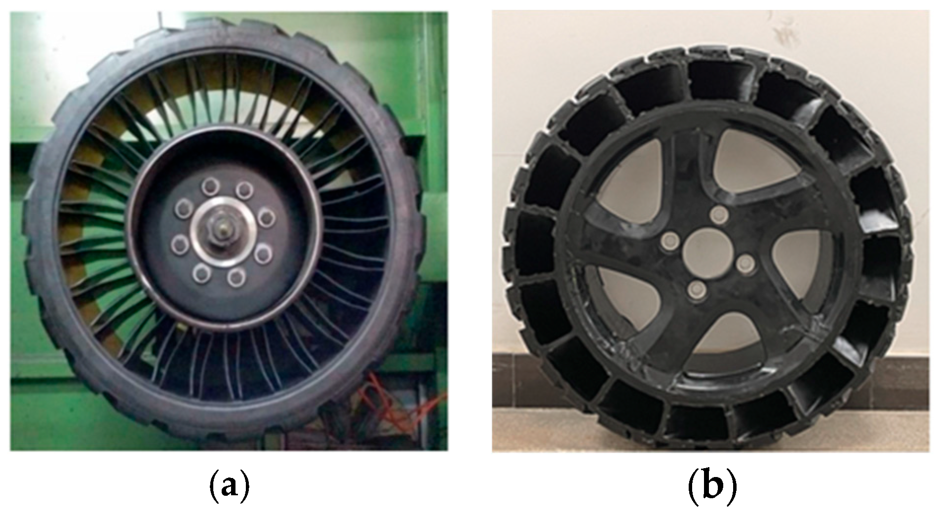
In addition to the above structural types, the spoke-plate structure has also attracted much attention. Xue et al. [52] proposed a new type of spoke-plate plastic tire and studied its grounding performance and mechanical characteristics under static load conditions. The tire combined polyurethane spokes with a rubber tread (Figure 14). Different from common spoke-type NPTs, this spoke-plate tire achieves load support and buffering through integral polyurethane spokes. It also shows unique advantages in terms of grounding performance and mechanical characteristics. It can achieve a more reasonable grounding imprint, a more uniform distribution of grounding pressure and higher radial stiffness.
To sum up, through parameter adjustment and innovative design of the porous structure, the goals of load capacity enhancement, stress concentration reduction and tire performance improvement are achieved. The advantages of the spoke structure are utilized for optimal design to achieve light weighting and improved load-bearing capacity. Some optimizations are applied to significantly improve the wheel’s stab resistance, load-bearing uniformity and adaptability to complex road conditions. These include the design of the suspension hub bearing structure, the parameters of the elastic ring group and the layout of the hinge group of the ME wheel.
Currently, significant achievements have been made in the structural research of pneumatic and NPTs. Beyond the research content reviewed above, optimizing thermal characteristics and reducing noise are also important development directions for safety tires. However, there is still a lack of such research. Future research should focus on optimizing the thermal design of these tire structures to enhance thermodynamic performance. Additionally, tread pattern optimization and the acoustic damping properties of porous and spoke structures could be leveraged to address existing noise challenges.

3. Material Design of Safety Tires

3.1. Materials for RFTs

Research on RFT materials primarily focuses on the inserts body structures of ISRFT and the SIR of SSRFT.

3.1.1. Materials for Inserts Body

Material selection for inserts body requires consideration of density, strength limit, Poisson’s ratio, cost and maintainability. To focus on the impact of material mechanical characteristics on overall tire performance, Zang et al. [15] proposed a combined ISRFT structure assembled with standard rims. They investigated three inserts body materials—Q235 steel, ZL114 aluminum alloy and polyurethane—under zero-pressure conditions. Considering both load-bearing capacity and lightweight design, they found that ZL114 aluminum alloy was an ideal inserts body material. Huang et al. [53] found that tires with foamed E-TPU inserts body can effectively bear vehicle weight when underinflated, with minimal increase in wheel sinkage. The inserts body exhibits uniform force distribution, demonstrating excellent cushioning and load-bearing capabilities.
Current research primarily focuses on the influence of mechanical characteristics on tire performance, while research on inserts body materials remains limited. Future studies could explore material performance under extreme conditions, such as high-temperature and subzero environments. Investigating the internal relationship between material microstructure and macroscopic characteristics from a microscale perspective will help develop more targeted high-performance inserts body materials. Additionally, optimizing the synergistic design of inserts body structures and materials can enhance material adaptability to complex stress environments. These can further improve the comprehensive performance of RFTs.

3.1.2. Materials for Sidewall Insert Rubbers

SSRFT is filled with SIR featuring high hardness, low heat generation, high elasticity and excellent fatigue resistance in the sidewall area. It prevents damage caused by high-speed driving after tire deflation.
Most research focuses on different rubber material systems to optimize the performance of SIR. Yu et al. [54] studied the blending ratio of natural rubber (NR) and neodymium-based polybutadiene rubber (NdBR). They found that when the blending ratio ranges from 45/55 to 60/40, the composite rubber exhibits optimal comprehensive physical characteristics. As the NR/NdBR ratio increases, the tensile characteristics of the blended rubber improve, but its flex resistance decreased, heat generation increased, and NdBR showed poor processing performance, filler dispersion and low tear resistance during use. Therefore, Ni et al. [55] investigated the application of high-cis polybutadiene composite rubber VCR617 as a substitute for NdBR in SIR. The results showed that VCR617 provides better reinforcement and hardening effects, increasing rubber hardness, 100% modulus, tensile strength and tear strength. Meanwhile, it reduces heat generation and improves wet skid resistance. The zero-pressure durability of prototype tires increased by 9%, with all indoor performance test results meeting national standards and outperforming NdBR-based tires. Ren et al. [56] studied the application of carbon black-modified low-cis polybutadiene rubber (LCBR) in SIR. The results showed that the vulcanization characteristics of the rubber compound changed slightly, with prolonged scorch time and slightly degraded processing performance. However, the modulus increased, the tensile strength and elongation at break remained stable, and heat generation was significnalty reduced. RFTs prepared with LCBR exhibited better zero-pressure durability.
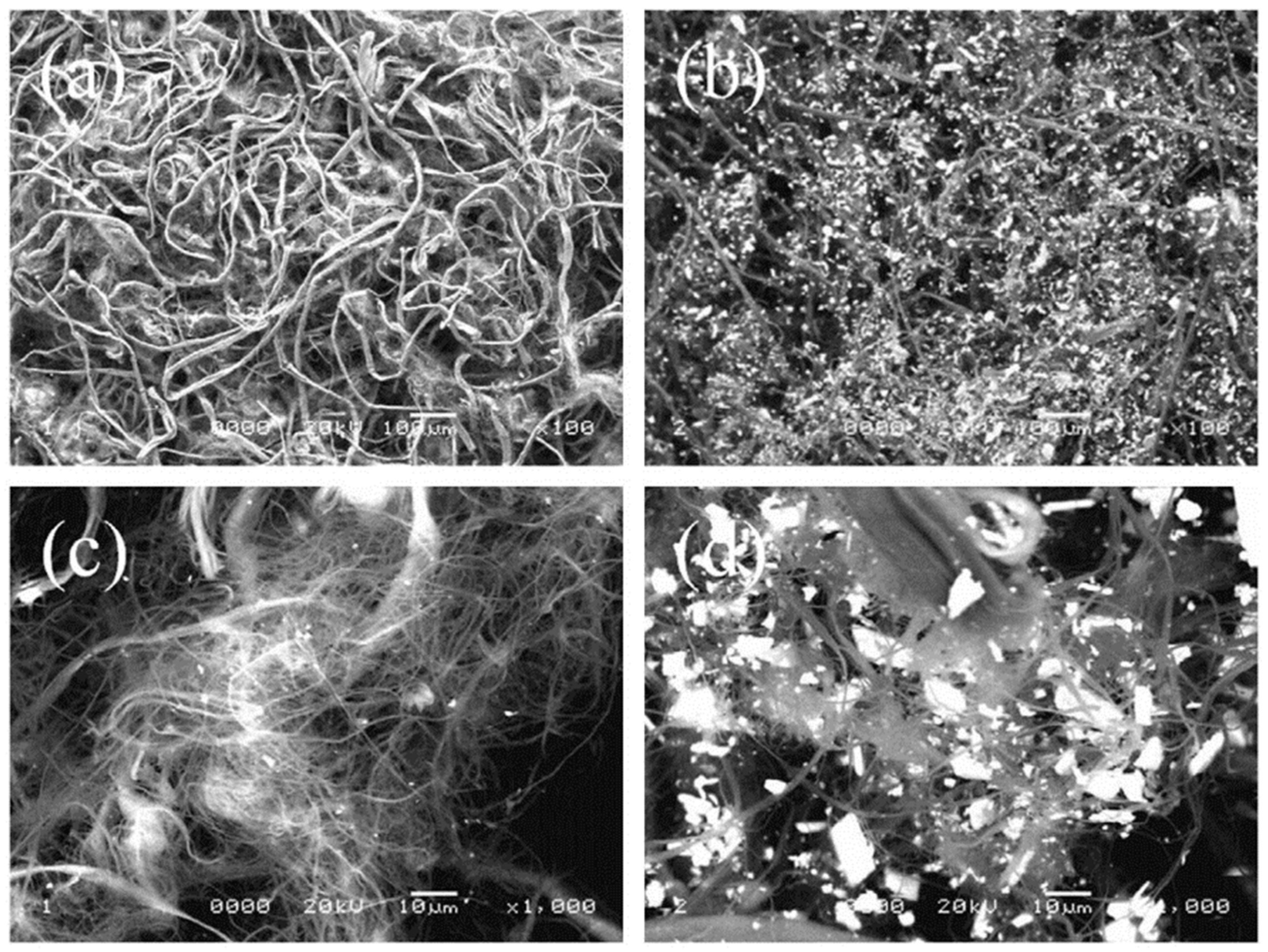
Additionally, some studies focus on performance enhancement of SIR using reinforcing agents. To improve the durability of RFTs by preventing sidewall folding under zero pressure, Park et al. [57] developed a masterbatch (MB). The masterbatch is made by mixing ZnO-treated aramid pulp (AP) fibers with natural rubber (NR). It has been applied to the sidewall insert layer compound of RFTs, as shown in Figure 15. The study found that increasing the AP content improved the mechanical characteristics of the composite and reduced hysteresis. However, compounds with excessive fiber content showed poor fatigue resistance and fiber dispersion. Tires with 1 phr AP fiber exhibited the best run-flat durability time.
Current research has evolved from single rubber materials to simple blends, combining the advantages of different rubbers to develop new materials and preparation processes. These efforts primarily aim to enhance the performance of SIR. Simultaneously, studies have investigated the impact of reinforcing agents on the properties of such rubbers.

3.2. Materials for NPTs

NPTs are significantly different from traditional pneumatic tires in terms of materials and manufacturing process. The materials mainly include tread, support structure, skeleton and adhesive. The manufacturing technology mainly includes compression molding, injection molding, centrifugal casting and 3D printing. This section will elaborate on the elastic support material of NPTs and the integration of multi-material and manufacturing processes.

3.2.1. Material for Elastic Support

Common elastic support materials for NPTs include polyurethane (PU), thermoplastic polyurethane (TPU), fiber-reinforced composites, etc. PU is a polymer material formed via the reaction between isocyanate and polyol, with its molecular chain comprising soft segments and hard segments. The soft segments provide flexibility, while the hard segments contribute strength and rigidity. PU demonstrates excellent elasticity and mechanical characteristics. When used to fabricate elastic supports for NPTs, it exhibits notable characteristics, such as high tensile strength, high wear resistance and low rolling resistance. However, under high-load and high-frequency deformation conditions, PU suffers from heat buildup issues. These issues can cause problems such as melting, tearing and the delamination of layers during vehicle operation. These issues ultimately result in the deterioration of mechanical performance, limiting the broader application of PU [11]. To address this challenge, researchers are focusing on enhancing the heat resistance of PU to optimize its comprehensive performance. Hu et al. [58] synthesized a polyurethane elastomer from polycarbonate diol, 1,5-naphthalene diisocyanate and 1,4-butanediol. This elastomer features high heat resistance and self-healing capabilities, and their study demonstrated comprehensive performance comparable to that of existing environmentally friendly tires. To achieve improved durability, stiffness and ride comfort, Priyankkumar et al. [59] compared the properties of three distinct spoke designs and six nonlinear polyurethane formulations. They also proposed an optimal combination of material and structure for NPT applications.
TPU belongs to the PU. Its molecular structure features a unique hard-segment-to-soft-segment ratio and bonding pattern. This endows it with thermoplastic characteristics—namely, the ability to melt and flow when heated, cure upon cooling and be reprocessed multiple times. Beyond the general characteristics of PU, TPU exhibits outstanding high elasticity, strength, wear resistance, cold resistance and processing performance. It boasts high elastic recovery, quickly returning to its original shape after stretching or compression; moreover, its performance remains relatively stable across different temperatures. Leveraging TPU’s unique molecular architecture and performance advantages, many scholars have explored its applications in NPT research in recent years. Wang et al. [60] conducted a detailed characterization of TPU materials through tensile tests, dynamic mechanical analysis (DMA) and other experiments. They proved that TPU exhibits superior wear resistance compared to natural rubber (NR), butadiene rubber (BR) and styrene-butadiene rubber (SBR).
Additionally, fiber-reinforced composites (FRCs) have garnered significant attention in the NPT field. As high-performance materials, FRCs consist of reinforcing fibers and a matrix material. They possess inherent advantages such as high strength, high modulus and low density, which effectively reduce structural mass. Wang et al. [61] proposed the carbon-fiber-reinforced polyethylene terephthalate (PET /CF) honeycomb structure as the support structure of NPTs. Compared with the traditional elastomer support structure, its bearing capacity and stability are stronger. Andra et al. [62] discussed the application of glass fiber and carbon-fiber-reinforced polymer composites in NPTs. Through FEM and parameter research, a key finding was obtained. Reasonable design of spoke structure and selection of material parameters can effectively improve the bearing capacity of tires and reduce weight. At the same time, it also points out the advantages and limitations of inelastic reinforced polymers in NPT design.

3.2.2. Multi-Material and Manufacturing Process Integration

The traditional forming technology of pneumatic tires includes drum forming, two-step forming, one-step forming and so on. Although it can achieve high precision, it requires complex equipment, high energy consumption and low yield. NPTs have complex supporting structures and are difficult to adapt to conventional molding. At present, the molding methods for NPTs include injection molding, centrifugal casting and 3D printing. However, the research still faces the challenges of material strength and fatigue life, and a collaborative breakthrough in materials and molding technology is urgently needed. Therefore, the current research focus has shifted to the integration and innovation of materials and manufacturing processes.
The centrifugal casting process is often used to manufacture the PU-material tire-support structure. In the manufacturing process, the PU raw material is heated, melted and injected into the rotating mold. The centrifugal force generated by the mold rotation distributes the material evenly and fills the mold cavity. The injection molding process is suitable for thermoplastic materials such as TPU. Designing the injection mold reasonably and accurately controlling the parameters, including injection speed, pressure and temperature, can achieve the efficient production of complex tire structures. Three-dimensional printing technology is also known as additive manufacturing technology [63,64]. Compared with traditional tools, 3D printing can manufacture complex geometry without a mold. This advantage effectively avoids the technical defects caused by the difficulty of forming and demolding of the traditional complex-structure forming process, and it increases the diversity of product design. At present, the 3D printing technology used in the forming process of NPTs mainly includes fused deposition modeling (FDM) and selective laser sintering (SLS) technology. FDM technology is the most widely used 3D printing technology at present. It has unique advantages, such as simple operation, convenient equipment maintenance and low cost. Dezianian et al. [65] conducted a study using PLA, TPU and void structures as research materials, optimizing the appropriate tire-inflating unit. They successfully developed NPT samples with specific structural characteristics. Wang et al. [60] studied the printing process of TPU materials based on FDM technology through tensile tests and SEM observation. FDM technology was successfully applied to 3D-printed NPTs based on PU materials. Suvanjumrat et al. [66] studied the mechanical characteristics of 3D printing materials suitable for spoke NPTs. The vertical stiffness of the sample examined by FEA was compared with that of the actual NPT. This comparison verified the feasibility of using 3D printing to construct complex spoke geometries.
In the research of multi-material NPTs, researchers can use FEA to simulate and analyze the mechanical characteristics of different material combinations in tire structures. Rugsaj et al. [67] used an innovative method involving water-jet cutting technology to prepare tensile and compressive test samples of Michelin tire ‘TWEEL’. The stress–strain relationship of the material test results was fitted to select the appropriate constitutive model for FEA. This model was compared with the physical experiment to verify the hyperelastic material model. Additionally, the elastic modulus of the NPT spoke was accurately determined by the inverse method combining FEM and the gradient method based on optimization. It provided a new method for further studying the material characteristics of complex-shape products and structures [68].
However, in actual production, the integration of multi-materials and manufacturing process still faces many challenges. The compatibility problem between different materials may lead to insufficient interface bonding strength and affect the overall performance of the tire. The complexity of the manufacturing process also increases the difficulty of quality control in the production process. In the future, the research direction of NPT support structure materials can focus on the development of new high-performance composite materials. Additionally, efforts can emphasize combining the advantages of different materials to improve their comprehensive performance and exploring the deep integration of multi-materials with manufacturing processes. Combining multi-disciplinary knowledge such as material science, mechanics and manufacturing processes can enable the comprehensive innovation of NPTs, from material design to manufacturing. This integration will promote the development of NPT technology.
At present, the research on the three types of tire materials has gradually shifted from focusing on a single material to the study of composite materials. Among them, the inserts body material emphasizes improving the bearing capacity. The SIR focuses on reducing heat generation, while the NPT aims to reduce weight, minimize heat generation and improve overall lifespan. The design of composite materials has promoted the development of various characteristics. However, achieving the coordinated development of high rigidity, light weight, low heat generation and high bearing capacity at the same time remains a significant challenge.

4. Study on Mechanical Characteristics of Safety Tires

The mechanical characteristics of safety tires are the key indicators to evaluate their performance and reliability. They have a crucial impact on driving safety, handling stability and comfort of vehicles. In recent years, the research on the mechanical characteristics of RFTs and NPTs has advanced, and significant progress has been made.

4.1. Mechanical Characteristics of RFTs

The RFT enables emergency driving ability under zero pressure by strengthening the SIR and adopting the inserts body structure. In recent years, its mechanical behavior under zero pressure and pressure relief conditions has been a research hotspot. This section will systematically sort out the research results of its mechanical characteristics under pressure relief, zero pressure and typical working conditions. It will also clarify the breakthrough direction of current research and the bottleneck problems to be solved urgently.

4.1.1. Mechanical Characteristics Under Pressure Relief Condition

Bae et al. [69] proposed a new method to calculate the stiffness of tire structure based on the strain energy of ordinary tires and RFTs. The calculation of strain energy U is as shown in Formula (1). The relationship between the force generated by the deformation of the tire structure and the deflection of the tire were analyzed by the finite element method. The force-displacement relationship and the calculated force–displacement relationship under zero pressure were compared to verify the effectiveness of the method. In addition, they calculated the vertical and structural stiffness of two pneumatic tires and clarified each component’s contribution rate to the overall structural stiffness.
U = σ d ε
Here, σ represents stress; ε represents strain.
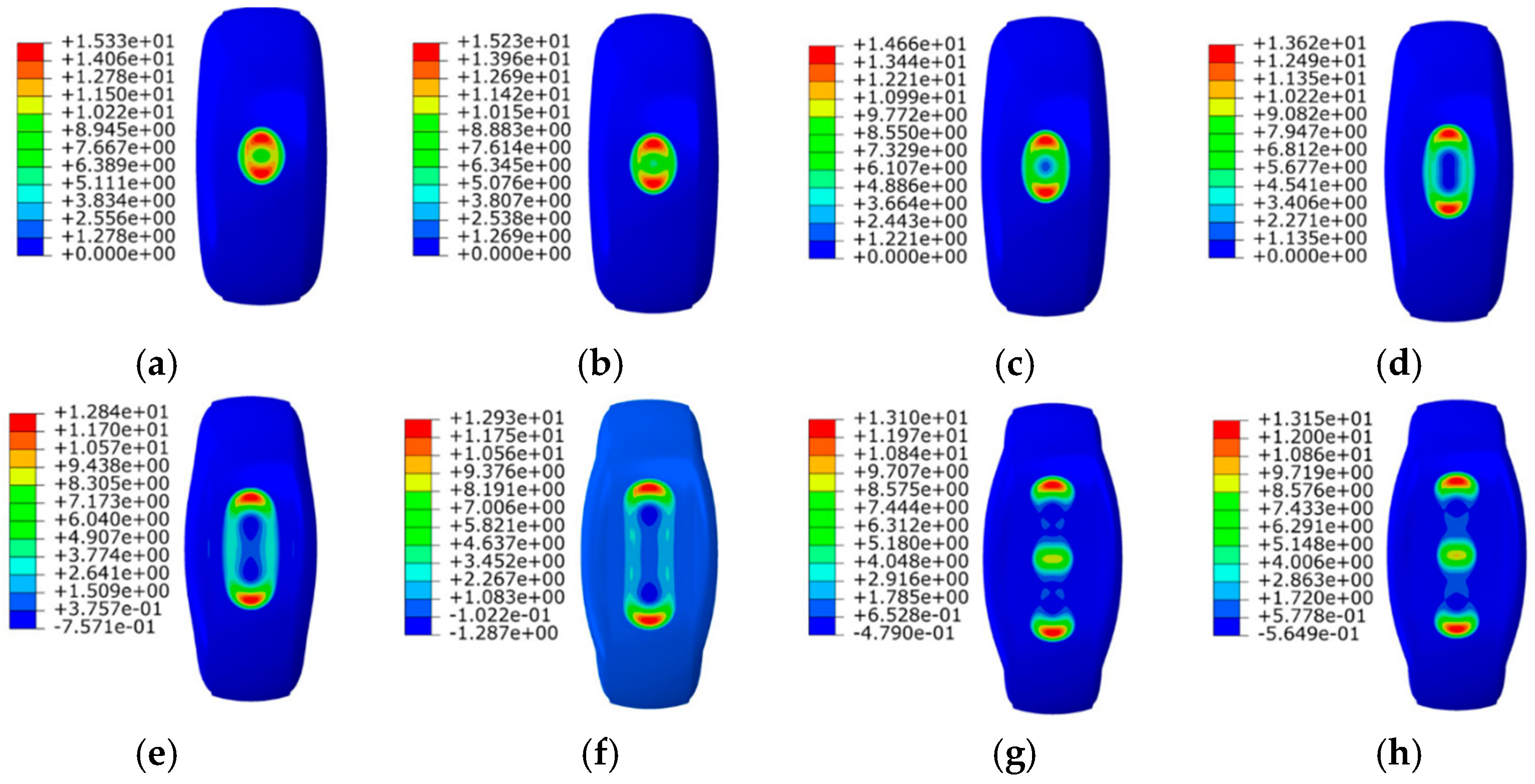
Wang et al. [70] studied the mechanical characteristics of the ISRFT in the process of pressure relief, established a large deformation nonlinear model and verified it by a bench test. They found that under the rated load, the tire displacement and inflation pressure show significant piecewise nonlinear characteristics. When the inserts body participated in the bearing, the radial stiffness of the tire increased significantly. During the depressurization process, the maximum contact pressure of the tire expanded from the center of the contact mark to both ends (Figure 16). When the inflation pressure dropped to 25 kPa, the central pressure of the tread gradually increased. This improved the tread warpage and improved the uniformity of contact pressure distribution under depressurization and zero-pressure conditions. The tire–road contact stress plays an important role in the vehicle’s handling stability. It is affected by parameters such as tire load, vehicle speed, road surface characteristics and slip rate. Zang et al. [71] established a theoretical model of the contact between the ISRFT and the ground and proposed a modified nonlinear ground pressure distribution. The FEM and bench test were used to verify and estimate the parameters. Combined with the brush tire model (Figure 17), the longitudinal and lateral force characteristics were analyzed. The green part of the picture can be regarded as the Inserts. The red part is the simulated brush, which is used to simulate and calculate the interaction relationship between the brush and relevant contact components in actual working conditions. Their results showed that the modified nonlinear ground pressure distribution had high fitting accuracy. The lateral force increased rapidly when the slip angle was less than 3°, and the growth rate slowed down when it was greater than 3°. The slip angle corresponding to the maximum lateral force under zero pressure was 3–5° larger than that under standard pressure. The longitudinal force increased rapidly when the slip ratio exceeded −0.2, and the maximum under zero pressure was 23.33% lower than that under standard pressure. A single theoretical model has limitations, so some empirical models are also used to analyze the friction behavior of tires. Pacejka et al. [72,73] established the Magic Formula model based on curve fitting of test characteristic data under different road conditions. This model requires continuous improvement with additional test data, and it is currently the most accurate model for test analysis and simulation, but it lacks predictive simulation capabilities.
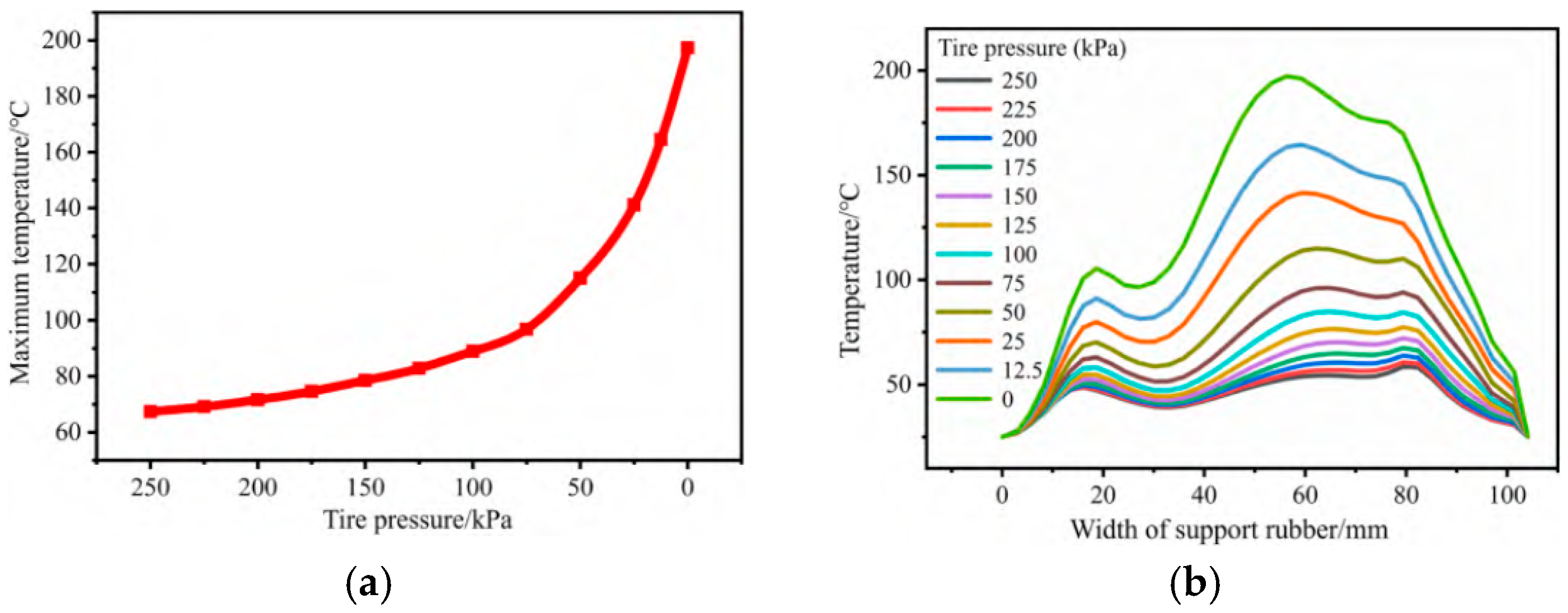
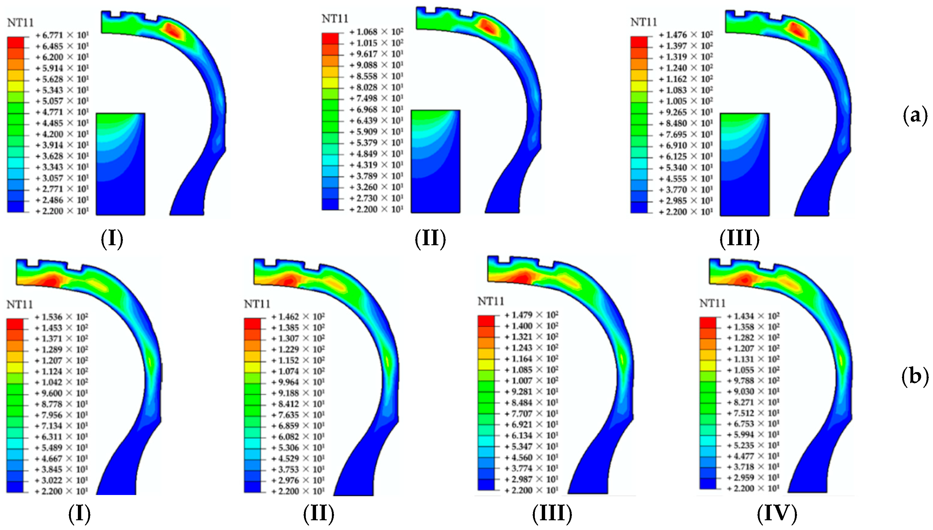
Zang et al. [74] established a large deformation nonlinear model and verified it by a bench test. They studied the mechanical characteristics and temperature characteristics of SSRFT in the process of pressure relief. Their study results showed that the contact area of SSRFT increased by about 223.8% compared with the rated pressure, while the effective contact area decreased by about 47.3%. At 50 kPa, the maximum Mises stress increased by about 69.8% compared with the rated pressure, and the uniformity of contact stress distribution became worse. As the tire pressure decreased, the maximum temperature of the tire increased. In terms of temperature characteristics, the maximum temperature of SSRFT was located on both sides of the shoulder under the rated tire pressure. As the tire pressure decreased, the high temperature area expanded to the bending part of the sidewall insert rubber. The maximum temperature growth trend increased sharply after 100 kPa (Figure 18a). In addition, the temperature characteristics of the SIR were closely related to the deformation form, and there was an obvious temperature peak movement phenomenon (Figure 18b).

4.1.2. Mechanical Characteristics Under Zero-Pressure Conditions

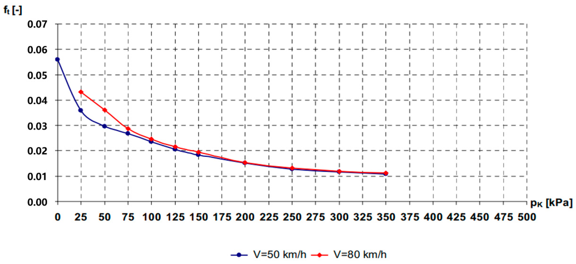
The friction between the tire and the ground affects the mechanical characteristics of the vehicle directly. Accordingly, the tire-related parameters (such as design, composite material, inflation pressure and temperature), road conditions and road surface parameters affect the frictional characteristics indirectly. During the periodic deformation of the tire, materials such as rubber and cords produce hysteresis loss. This hysteresis will cause energy dissipation, which is the main source of rolling resistance. In addition, the sliding friction loss of the contact zone during tire rolling is also a cause of rolling resistance [75]. Ejsmont et al. [76] experimentally measured the rolling resistance coefficient of the ISRFT under different inflation pressures. They found that the coefficient was basically independent of the inflation pressure between 200 and 350 kPa. When it was lower than 200 kPa, the coefficient rose rapidly. At 80 km/h, the rolling resistance was higher than that at 50 km/h (Figure 19). Under the zero-pressure condition, the rolling resistance increased significantly. When the tire was under zero pressure and the inserts body was in contact with the tread, the rolling resistance could be increased by 500% compared with the normal pneumatic tire. Meanwhile, the rolling resistance coefficient could reach about 0.06. This was due to the change in the internal structure of the tire. The part that originally relied on the inflation pressure support was changed to be borne by the inserts body, changing the mechanical characteristics of the tire. The rolling resistance calculation formula of the ISRFT is as follows:
F t = h · Z k · u z · b A
In the formula, Ft is the rolling resistance force (N), zk is the normal load of the wheel (N), uz is the radial deflection of the tire (m), b is the width of the contact trace between the tread and the ground (m), A is the area of the contact trace between the tire and the ground m2, and h is the lag coefficient.
To enhance the zero-pressure run-flat performance of ISRFT, Yang et al. [18] successfully established the RFT zero-pressure running spring-damping model and zero-pressure walking brush model. They clarified the differences between zero-pressure tangential force Fx0 (Formula (3)), lateral force Fy0 (Formula (4)), and aligning moment Mz0 (Formula (5)) and those under normal pressure. The design principle of inserts body was put forward, and the sample design and bench performance test were carried out.
F x 0 = b 1 0 l 1 τ x b 1 d x
F y 0 = b 1 0 l 1 τ y d x
M z 0 = F y 0 s 0
In the formula, b1 is the width of the inserts body; l1 is the length of the wrap angle arc; s0 is the zero-pressure towing distance. The brush model is a theoretical model that can describe the variation characteristics of the friction and torque of a tire. Assuming the tread is simplified to elastic bristles, the different states of the bristles in the adhesion zone and the sliding zone can intuitively explain the changes in tire force. Compared with other models, the brush model can more accurately describe the changes in longitudinal and lateral forces. It also captures the influence of pavement parameters on these forces [77,78].
Zang et al. [79] tested the load characteristics, lateral mechanical characteristics and grounding characteristics of ISRFTs. These tests were conducted under zero-pressure conditions with different loads, as shown in Figure 20a,b. The research showed that the zero-pressure load characteristics of the ISRFT were piecewise linear, related to the contact between the inserts body and the inner side of the tire. The zero-pressure lateral mechanical characteristics included different regions, and the lateral stiffness did not increase significantly in the slip zone, but the adhesion force decreased. The shape of the zero-pressure grounding imprint remained unchanged under a specific load, and the pressure distribution in the bearing area deteriorated. By establishing a FEM and conducting experiments, Zang et al. [80] studied the load and grounding characteristics of the ISRFT under zero-pressure conditions. They obtained its radial stiffness curve and contact pressure distribution, which provided a basis for tire performance analysis. The established that the ISRFT FEM was effective, and the reliability of the simplified model simulation was verified by static analysis. Under the condition of zero-pressure, the radial stiffness curve of ISRFT was nonlinear in the sidewall loading stage. It was approximately linear after the insert contacts the tire. There was a warping phenomenon in the distribution of grounding pressure. The distribution of grounding imprint obtained by the test was consistent with the simulation results, and the average contact pressure increased with increasing load.
Xue et al. [81] established a FEM and used the sequential thermo-mechanical coupling method to study the thermo-mechanical coupling characteristics of the ISRFT under zero-pressure conditions. They analyzed the steady-state temperature field (SSTF) at different speeds (Figure 21a) and compared the SSTF of the honeycomb-structured inserts body with the original tire (Figure 21b). The results showed that the temperature of the shoulder, tread and sidewall increased by about 1.6 °C, 0.67 °C and 0.37 °C, respectively, while the driving speed of the ISRFT increased by 1 km/h under the rated load at zero pressure. The temperature rise of the bead and other parts was small and insensitive to speed. Compared with the original ISRFT, the maximum temperature of the honeycomb ISRFT shoulder was reduced by about 30 °C; the SSTF distribution was more uniform. However, the maximum temperature of the tread increased by about 40 °C. The quality of the honeycomb inserts body was significantly reduced by 70.83%, 59.36%, 56.04% and 43.88%.

4.1.3. Mechanical Characteristics Under Typical Working Conditions

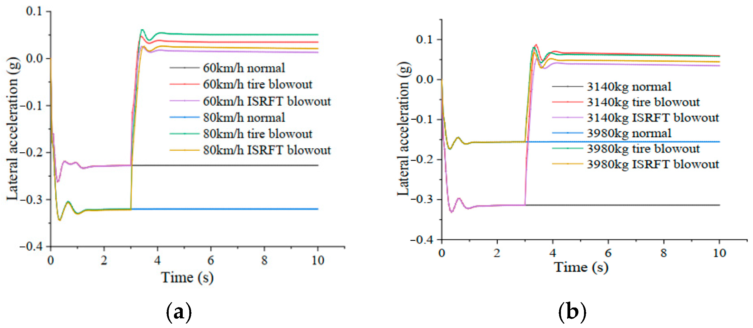
Under typical working conditions, the research on the mechanical characteristics of the RFT was important. It helps to ensure the safety of the vehicle, optimize the tire design and improve the overall performance of the vehicle. Many scholars have explored the mechanical characteristics of the ISRFT under typical working conditions from different angles and using various methods. Xie et al. [82] carried out a comparative road test on self-sealing RFT and ordinary tires. The results showed the following: the rolling resistance coefficient of the self-sealing RFT increased; the power, economy and smoothness were not significantly different from those of the ordinary tire; the braking performance was slightly improved; and the braking distance was shortened. In the protective test, the self-sealing RFT basically did not leak after being punctured by an object with a diameter of less than 8mm. It could travel 220 km normally and improved the safety protection performance greatly. The difference in braking performance is often closely related to the tire’s ground contact state. During braking, parameters have a significant impact on the contact stress between the tire and the ground. These parameters include camber angle, sideslip, combined camber angle and slip conditions [83]. Wang et al. [84] first studied the blowout characteristics of the ISRFT and established the ISRFT blowout model based on the UniTire model. In addition, they compared the blowout characteristics with those of an ordinary tire under steering driving conditions on the Simulink/Carsim platform. The results showed that the tire blowout characteristics of ISRFT were similar to those of ordinary tires at different speeds and loads. However, the displacement and stability of the ISRFT were better. Taking the right-turn left-front tire blowout as an example, they made the following findings. The vehicle speed was associated with the turning radius, lateral acceleration (Figure 22a) and sideslip angle of the vehicle during normal driving. The higher the former, the greater the latter. The same applied to the degree of deviation of each parameter from the normal value after the tire blowout. The larger the load, the smaller the turning radius, the lateral acceleration (Figure 22b), the sideslip angle and the yaw rate. The UniTire model used in the above study by Wang et al. is a nonlinear unsteady-state tire dynamics model. It is simple in form and high in calculation accuracy. It is also suitable for studying the variation characteristics of longitudinal force, lateral force and aligning torque under different road friction conditions, load, speed and other parameters [85]. In addition to the tire blowout condition, based on the 37 × 12.5R16.5 ISRFT, Wang et al. [86] explored the difference between the ISRFT and an ordinary tire. The research was under typical working conditions, such as near-zero pressure and normal driving, using theoretical analysis, static tests and dynamic characteristics comparisons. The results showed that the displacement increases sharply and the stiffness decreases at near-zero pressure. In terms of lateral mechanical characteristics, the lateral adhesion decreased, and the lateral stiffness increased significantly at the slip point under zero pressure. When driving in a straight line, the trajectory displacement of the ISRFT was smaller than that of the ordinary tire at low speeds. However, it was the opposite at high speeds. When steering, the critical steady-state speed of ISRFT was higher, and the positive camber angle had an inhibitory effect on its sideslip and vertical force. In the two-lane transformation, the difference between the ISRFT and the target trajectory was smaller. The small negative camber angle could improve its displacement and correlation performance.

4.2. Mechanical Characteristics of NPTs

4.2.1. Static Mechanical Characteristics

The research on the static mechanical characteristics of NPTs mainly focuses on the optimization of spoke parameters, structural design innovation and high-precision modeling methods. These approaches can balance the requirements of bearing capacity, lightweight and durability. Their core characteristics mainly include vertical stiffness, radial stiffness and grounding characteristics.
  • Vertical stiffness
The vertical stiffness reflects the ability of the tire to resist deformation in the vertical direction and determines the bearing stability and cushioning performance directly. Its size is closely related to the thickness, shape and topology of the spoke. Rugsaj et al. [87] studied the effect of spoke thickness on the vertical load support performance of NPTs (Figure 23). Their results showed that an increase in spoke thickness (from 3.8 mm to 7.8 mm) could significantly improve the vertical stiffness (from 658.17 N/mm to 796.91 N/mm), and the maximum local stress decreased with the increase in spoke thickness (from 4.5 MPa to 2.29 MPa). The weight of the spoke was positively correlated with the thickness, and the weight increased by about 105% when the thickness increased to 7.8 mm. When the vertical stiffness of the optimized spoke with a 5 mm thickness was equivalent to that of the pneumatic tire, the maximum stress was reduced to 2.29 MPa. The safety factor was 2.62, and the fatigue life was effectively improved under the same condition. Sim et al. [88] compared and analyzed the vertical stiffness characteristics of three tire models with different spoke shapes (Figure 24). The calculation results showed that the model with the minimum fillet in the stress concentration area of the spoke had the highest vertical stiffness. It also had the smallest deformation and the best stability. The research results provided key design criteria for spoke shape optimization, which could improve the bearing capacity and durability of tires.
Phromjan et al. [89] proposed six kinds of arrangements of spokes on the circumference of NPTs. They studied the weight reduction effect of spokes by the FEA method and solved the problem of large weight and high energy consumption of the NPTs produced in recent years. The vertical stiffness function with the number and thickness of spokes as variables was established, and the optimization design and manufacture were carried out. The spoke topology directly affected the load distribution and cushioning performance. Seong et al. [90] optimized the design of NPTs by the generative adversarial network (GAN), focusing on exploring the influence of different spoke structures on static mechanical characteristics. Due to the flexibility of the hexagonal structure in the vertical and shear directions, the honeycomb spokes could provide a high compressive strength-to-volume ratio. The plate-shaped spokes support the load through vertical stiffness, while the triangular and curved spokes have their own characteristics in structural stability. In this study, ProjectedGAN was used to generate a highly consistent pattern (such as Figure 25). It effectively maintained the circular structure of the tire and reduced the deformation, thereby optimizing the load distribution uniformity and static bearing capacity. A quantitative evaluation showed that the image generated by ProjectedGAN was closest to the real design in statistical distribution (FID = 13.41) and perceptual similarity (LPIPS = 0.3477). These indicated that the generated structure was closer to the actual mechanical performance requirements, which provided a high-fidelity design basis for subsequent static mechanical analysis.
  • Radial stiffness
Radial stiffness characterizes the deformation resistance of the tire along the radius direction, affecting rolling resistance and high-speed stability. It involves a rigid–flexible coupling structural design and multi-condition response. Zhao et al. [91] established a pseudo-rigid body flexible coupling model to analyze its radial stiffness characteristics. They optimized the radial stiffness of the pseudo-rigid NPT and obtained the linear relationship between the sinking amount and the load. The research showed that the ride comfort was better than the pneumatic tire at low speeds, and the rigid structure intensified the vibration at high speeds. Rugsaj et al. [33] developed NPTs for skid steer loaders based on the new X-shaped design. Then, they studied the influence of geometric parameters on stiffness through FEA of its quasi-static performance. They provided a reference for manufacturing a series of NPTs. Du et al. [92] combined a finite element and neural network to analyze the ME wheel hinges. They analyzed the influence of the length and distribution number of ME wheel hinges on the camber angle and turning performance. The results showed that increasing the length of the hinge would reduce the lateral force but increase the aligning moment. In contrast, increasing the number of hinge distribution had the opposite effect. The neural network model had high prediction accuracy, which provided data support for tire structure optimization and vehicle performance matching.
  • Grounding characteristics
Grounding characteristics focus on parameters such as pressure distribution and grounding area in the contact area between tire and road surface. They are directly related to grip force, wear uniformity and ride comfort. With the diversification of NPT structural design, the traditional simplified model research has gradually shifted to complex nonlinear models. The grounding characteristics of NPTs depend not only on the spoke structure but also on road roughness. The later affects the effective shear stiffness and lateral stiffness of the tread, which in turn influence the ground pressure distribution [93]. Liang et al. [94] established a static grounding model considering the nonlinear stiffness of the spokes. The shear band was simplified as a circular Timoshenko beam. The contact between the tire and the road surface was used to iteratively compensate the reaction force of the road surface. It obtained the deformation of the NPT with nonlinear spokes on the road surface. The model could simulate the structural characteristics and static grounding behavior of NPT more realistically. Liang et al. [95] established a 3D FE model of the UPTIS NPT, analyzing its mechanical characteristics under radial force and combined loading conditions. The results demonstrated that the flexible-spoke design’s stiffness, contact pressure distribution and stress-deformation behavior enabled simultaneous high load-bearing capacity and cushioning performance. This provided a theoretical basis for the static structural optimization of UPTIS tires. LU et al. [96] established an NPT structure characteristic analysis ring model. They used the structure to explore the influence of spokes and shear band parameters on both the vertical deflection and the contact surface length of the tire. They also studied how the parameters affected the static mechanical behavior of NPTs, including the radial stiffness coefficient of the spokes and the radial spring stiffness of the shear band. These explorations provided guidance for the design of NPTs.

4.2.2. Dynamic Mechanical Response

The research on dynamic mechanical response of NPTs mainly focuses on rolling resistance, vibration, impact and aerodynamic characteristics.
  • Rolling resistance
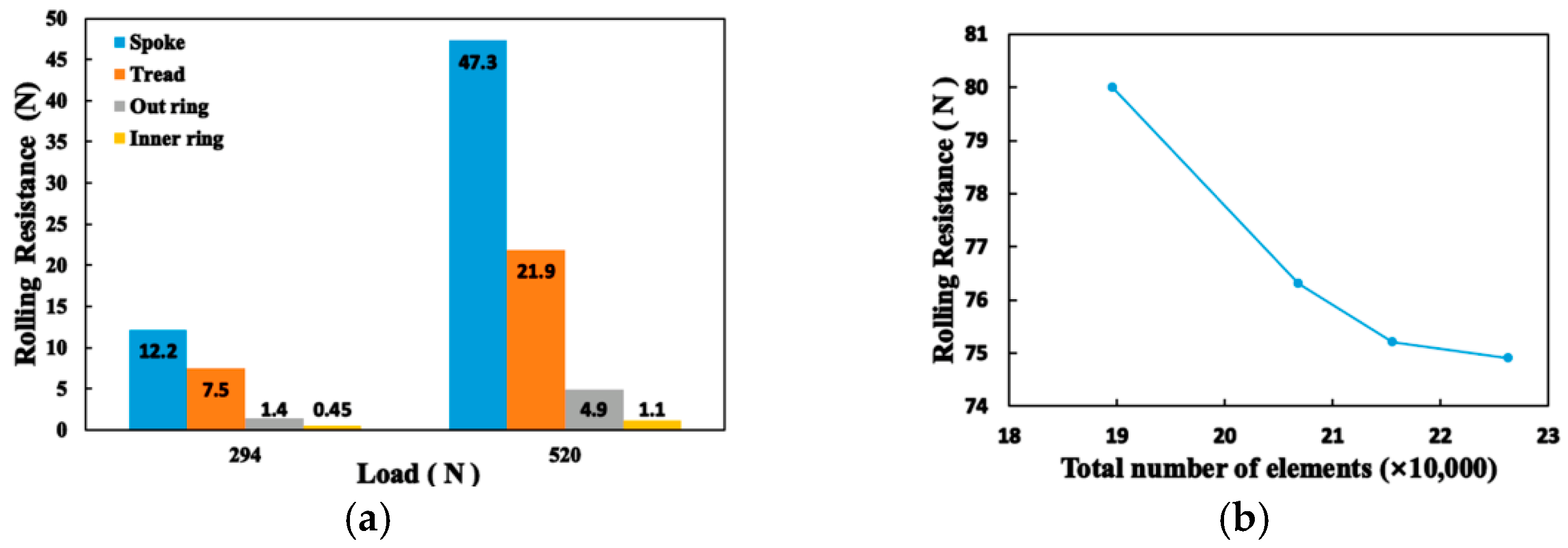
Rolling resistance is the core evaluation index of the dynamic mechanical characteristics of NPTs. The existing research has been extended from a single mechanical modeling to multi-physical field coupling. The research scenarios have also developed from conventional working conditions to extreme environments. Compared with the pneumatic tire, the NPT can avoid the increase in rolling resistance caused by the inflation pressure problem, but they are also affected by material hysteresis loss and sliding friction loss. Guo et al. [97] designed a ME wheel and established a tread prediction model under steady-state conditions. They studied and determined three structural parameters affecting rolling-resistance ground length (CL), ground width (CW) and radial stiffness (SR). The quantitative relationship model between parameters and resistance was established, which provided support for the quantitative prediction of rolling resistance of NPTs. Liu et al. [98] proposed a solution strategy for steady-state temperature field and rolling resistance based on explicit transient rolling analysis and thermo-mechanical coupling. Then, they carried out experimental verification in low-speed and low-load NPTs, as shown in Figure 26. The results showed that the load and speed had a significant effect on the steady-state temperature field. Particularly, the spoke had the greatest influence on the rolling resistance, followed by the tread, while the speed had no obvious effect on the rolling resistance. In the field of extreme environment application expansion, Sidhu et al. [99] focused on Mars exploration. They used smooth particle hydrodynamics (SPH) technology to construct the interaction model between NPTs and loose soil. They simulated the rolling resistance coefficient and provided a cross-scale simulation method and structural optimization path for the tire design of planetary exploration vehicles.
  • Vibration and shock
The vibration and impact characteristics of tires were the core factors affecting vehicle ride comfort, durability and handling stability. Aiming at the vibration problem of NPTs, Li et al. [100] simulated the original tire and optimized tire after the bionic design of NPTs. They studied the vibration and grounding characteristics of the two tires when crossing obstacles, Meanwhile, they analyzed the influence of different speeds and obstacle heights on the vertical and longitudinal vibration of the two tires. Chen et al. [101] constructed a 3D FEM of pneumatic tires and flexible-spoke NPTs. They designed simulation schemes to study the cushioning and lateral performance of tires. Through orthogonal experiments, it was found that NPTs recovered stability faster after passing over bumps. The lateral force bearing capacity was 1.9 times over that of pneumatic tires. The element angle α had the greatest impact on their cushioning and lateral performance, with an impact level exceeding 90%. These findings provided a new direction for the tire design of unmanned ground vehicles.
  • Aerodynamic characteristics
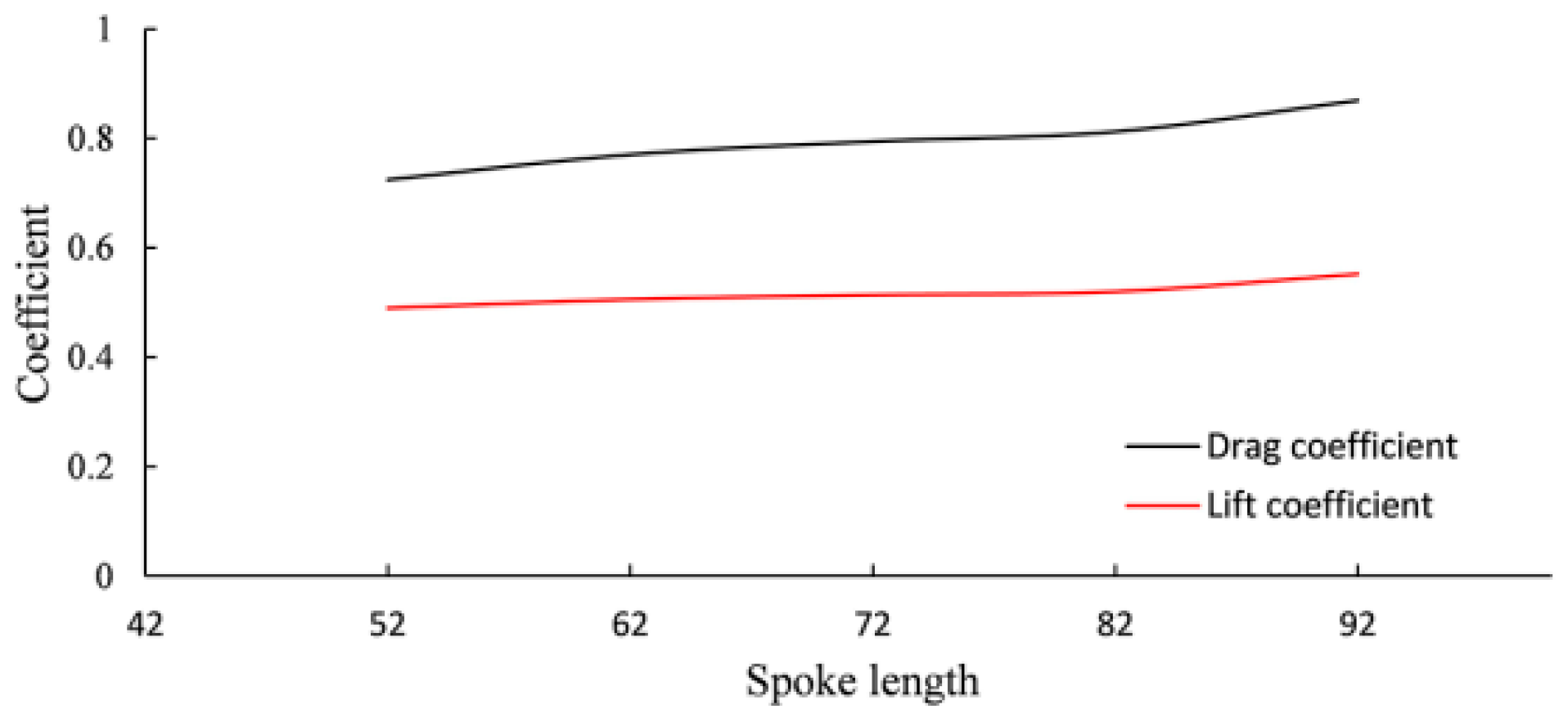
In addition to rolling resistance, vibration and impact characteristics, aerodynamic characteristics are also key to the study of dynamic mechanical response of NPTs. Zhou et al. [102] compared the airless tire with elastic support (ALTES) and pneumatic tires. The results showed that the drag coefficient of the vehicle with ALTES was lower than that of the vehicle with pneumatic tires at low speeds. The opposite was true at high speeds. In the wheel–vehicle aerodynamic interaction, the vehicle equipped with ALTES had a significant drag reduction effect. Although the NPT had advantages in structural durability, its open spoke design resulted in a weaker aerodynamic performance compared to traditional pneumatic tires. Li et al. [103] used Fluent software to carry out a multi-physical-field coupling simulation of NPTs and studied the influence of structural parameters such as tire width (B), spoke length, spoke thickness and curvature on aerodynamic coefficient systematically. An increase in spoke thickness and a decrease in tire width can significantly reduce the air resistance coefficient (as shown in Figure 27). In addition to aerodynamic performance, the traction performance of NPTs in road driving was also critical. Sidhu et al. [104] studied the effects of four spoke shapes on the NPTs’ traction performance in road applications by using FEA. The shapes include honeycomb, modified honeycomb, recessed honeycomb and straight spoke. Considering the factors of longitudinal speed and vertical load, the traction coefficient was evaluated to reveal the changes in design performance of different spokes. This provided valuable insights for optimizing the design of NPTs and improving their traction, durability and efficiency in road applications.

4.2.3. Mechanical Characteristics Under Complex Conditions

The mechanical response mechanism of NPTs under multi-physical field coupling has become a research hotspot. One of the important reasons is the expansion of the application scenarios of NPTs in complex working conditions. Scholars have systematically revealed the influence of complex load, special road surface and thermo-mechanical coupling on the mechanical characteristics of NPTs. They utilized the combination of experimental tests, numerical simulation and theoretical modeling. Off-road scenarios are typical of complex working conditions, where the mechanical characteristics of tires need to adapt to deformable soils, such as clay, loam and sand. Specifically, the shear strength of clay is higher than that of loam and sand. The mechanism of force transfer in soil is quite different from that in rigid pavement. Sharaf et al. [105,106] developed two models to study the performance of tires in off-road scenarios. The first was to establish a 14-DOF mathematical model of an off-road vehicle. They combined the terrain mechanics and vehicle dynamics of the tire contact with the soil. Then, the combination was used to study the handling performance of 4 × 4 vehicle under transient and steady-state conditions. Secondly, they studied the dynamic performance of a permanent all-wheel drive off-road vehicle with a viscous locking device. To simulate the dynamic characteristics of the vehicle on deformable soil, a comprehensive computer model of the dynamic simulation of the all-wheel drive off-road vehicle was established. It was proposed that the desired vehicle performance could be achieved. The method involved adjusting the parameters of the silicone oil and establishing the adjustment process of such devices in a simulated environment.
In addition to soil characteristics, scholars have also carried out certain studies on the mechanical characteristic of NPTs in the obstacle impact scenario. Jackowski et al. [107] compared the characteristics of the center line of the test object under three different normal loads and different surfaces. These surfaces included a plane rigid surface and a single triangular obstacle. They used a quasi-static test and FEM verification in the comparison. They analyzed the influence of the load-bearing structure of the geometrically shaped NPT (for all-terrain vehicle-ATV/utility task vehicle-UTV). This load-bearing structure was determined from the relationship between the radial stiffness of the wheel and the load. Zang et al. [108] studied the mechanical characteristics and stress distribution of rhombic NPTs under three complex conditions. Their research showed that the increase in obstacle height would affect the stress concentration point under a unilateral obstacle. Specifically, the stress concentration point shifted from the tread to the spoke structure. The vertical displacement and contact pressure showed decoupling characteristics. When the obstacle surface made contact, increasing the width from 50 mm to 150 mm could reduce the maximum stress by about 50%. Meanwhile, the stress concentration point shifted to the inside of the spoke. For bilateral obstacles, an increase in obstacle height led to the transfer of the maximum stress point from the ground to the obstacle contact area. The ground reaction force could alleviate the stress concentration after the tire was grounded. Ku et al. [37] extended the research to the multi-condition physical coupling field. Through the virtual simulation technology, the steady-state mechanical characteristics of the flexible-spoke NPT under multiple working conditions were studied. They obtained the steady-state mechanical characteristic curves under different working conditions. Under a single working condition, the force or torque of the tire would change with the motion state of the tire under the same load. When the load gradually increased, the longitudinal stiffness, lateral stiffness, aligning stiffness and camber stiffness and their corresponding peaks all showed an increasing trend. Under the composite working condition, the effect of camber on the lateral force and aligning moment was directional. The effect would promote or inhibit the generation of lateral force and aligning moment, but had little effect on the longitudinal force. Fu et al. [109] studied the stiffness, grounding characteristics and fatigue performance of flexible-spoke NPTs. Their study was conducted under thermo-mechanical coupling by combining numerical analysis with prototype tests (Figure 28). In this figure, the color contour represents the displacement distribution, red indicates regions of higher displacement and blue indicates regions of lower. Yuan et al. [110] used numerical simulation to analyze the external flow field characteristics of NPTs with flexible spokes. The analysis was conducted from the perspective of aerodynamic performance optimization. The spoke shoulder and cavity led to an increase in aerodynamic drag coefficient (Cd). A five-factor four-level orthogonal test was designed to optimize the spoke parameters. The aerodynamic drag coefficient (Cd) and ventilation moment (VM) were reduced by 6.25% and 16.55%, respectively, while maintaining the stiffness of the spokes.

5. Conclusions and Prospects

5.1. Conclusions

This paper focuses on the safety tire system and systematically reviews domestic and international research progress on its structural design, materials, manufacturing process and research methods. It summarizes the research results of the mechanical characteristics of RFTs under different working conditions and the mechanical characteristics of NPTs. The main conclusions are as follows:
(1)
Structural design
All three tires exhibit their unique structural characteristics. The ISRFT relies on optimizing its internal support structure, which can achieve lightweight and improve heat dissipation. The SSRFT enhances load-bearing capacity under zero-pressure conditions by increasing the stiffness of the SIR. For NPTs, the optimized design of porous structures and spoke structures can reduce stress concentration and improve load-carrying capacity. The structural characteristics of the ME wheel enable it to adapt to complex road conditions.
(2)
Material design
The goal of material research for RFTs is to enhance support performance under zero-pressure conditions. The inserts body of ISRFT focuses on screening the mechanical characteristics of engineering materials. For the SIR of SSRFT, it involves various rubber systems, new alternative rubbers and fiber reinforcements. NFTs mostly combine composite materials with advanced manufacturing processes. This combination optimizes tire heat resistance, lightweight characteristics and load-carrying capacity, while also resolving the contradictions in the performance of single materials.
(3)
Mechanical characteristics
The research on the mechanical characteristics of RFTs under different conditions is reviewed. Under pressure relief and zero-pressure conditions, the tire exhibits nonlinear mutations such as increased radial stiffness, expanded ground pressure and increased rolling resistance. Meanwhile, thermal-mechanical coupling intensifies. Optimization improves local performance but fails to balance overall uniformity. Under tire blowout conditions, the tire shows advantages in stability but struggles to balance emergency safety and normal handling. For NPTs, static performance is centered on spoke topology optimization, with spoke parameters adjusted to balance stiffness and grounding characteristics; rolling resistance mainly depends on spoke structure; vibration and impact are influenced by structure, material and dynamic load; and aerodynamic performance is determined by the overall structure. Under complex conditions, the influence of complex loads, special road surfaces and thermal-mechanical coupling on the mechanical characteristics of NPTs is mainly studied.

5.2. Prospects

From the above research review, it can be seen that scholars at home and abroad have carried out a lot of research work on RFTs and NPTs, but there are still some difficulties and bottlenecks for breakthroughs. Therefore, from the perspective of structure-material-function collaborative optimization, this paper proposes three major paths that can be broken through in the future safety tire technology:
(1)
Integrate structural design with interdisciplinary approaches. By incorporating bionics, replace traditional hexagonal honeycombs with adaptive irregular honeycomb structures featuring lightweight thermal management integration. Construct a multi-physics-coupled topology optimization model to simultaneously address heat dissipation, structural stiffness, and lightweight requirements.
(2)
Synergize materials and manufacturing processes. Develop novel materials featuring enhanced strength, superior thermal dissipation, lightweight properties and environmental sustainability. Implement advanced noise-reduction technologies and cushioning materials to improve driving comfort. Achieve optimal balance between performance and lightweight through multi-material integrated manufacturing. Leverage smart manufacturing and 3D printing technologies to propel performance enhancement and sustainable development of safety tires.
(3)
Expand special-scenario applications. Develop high-temperature-resistant, puncture-resistant composite-structure tires for extreme environments, concurrently optimizing heat dissipation and self-healing capabilities to ensure long-term reliable operation under complex working conditions. Drive synergistic advancement between safety tire technology, autonomous driving, and intelligent connected vehicle (ICV) technologies.
In summary, future research still needs to accelerate the collaborative innovation of industry, academia, research and application, and deepen the interdisciplinary integration in order to break through the existing technical bottleneck, which will not only inject new development momentum into the tire industry, but also provide key support for the safe, efficient and sustainable development of the intelligent transportation system and help build a safer, greener and intelligent travel ecology.

Author Contributions

Writing—original draft preparation, L.Z. and J.S.; writing—review and editing, L.Z. and J.S.; resources, X.P.; supervision, F.L. and Y.D.; Conceptualization, Y.B. All authors have read and agreed to the published version of the manuscript.

Funding

This research was funded by the National Natural Science Foundation of China (grant number 52372357), Research Foundation of Nanjing Institute of Technology (grant number CKJA202205), Postgraduate Research & Practice Innovation Program of Jiangsu Province (grant number SJCX25_1261), Qing Lan Project (grant number Su teacher letter [2024] NO.14).

Data Availability Statement

No data was used for the research described in the article.

Conflicts of Interest

The authors declare no conflicts of interest.

Nomenclature

Ltotal length of sidewall inserts rubber of SSRFT, mm
Hmaximum thickness of sidewall inserts rubber of SSRFT, mm
Ustrain energy of elastic body, J
σstress elastic body, Pa
εstrain elastic body
Ftrolling resistance force of tires, N
bwidth of the contact trace between the tread and the ground, m
Aarea of the contact trace between the tire and the ground, m2
zkwheel normal load, N
uzradial deflection of tires, m
hlag coefficient of tires
pkinflation pressure of tires, kPa
frrolling resistance coefficient of tires
Fx0tangential force of tires, N
Fy0lateral force of tires, N
Mz0aligning moment of tires, Nm
b1width of the inserts body, mm
l1length of the wrap angle arc of the inserts body, mm
s0zero-pressure towing distance of RFT, mm
Vvelocity of different conditions, km/h
Nthe number of honeycombs

References

  1. Tong, J.; Yang, X.; Zhang, F.; Zhang, S.J.; Chen, B.C. Development of run flat tire technology. Trans. Chin. Soc. Agric. Mach. 2007, 38, 182–187. [Google Scholar] [CrossRef]
  2. Drozd, K.; Tarkowski, S.; Caban, J.; Nieoczym, A.; Vrábel, J.; Krzysiak, Z. Analysis of truck tractor tire damage in the context of the study of road accident causes. Appl. Sci. 2022, 12, 12333. [Google Scholar] [CrossRef]
  3. Jilek, P. Vehicle wheel positioning innovation on a machine for measuring the contact parameters between a tyre and the road. Arch. Automot. Eng.-Arch. Mot. 2023, 100, 31–43. [Google Scholar] [CrossRef]
  4. Shi, H.X. A Century of Tire Evolution: Tracing the Developmental Journey. Automob. Parts 2005, 44, 2. [Google Scholar]
  5. Gao, S.X.; He, J.Q.; Jie, L.Q. Run-Flat tires and their applications in military vehicles. Tire Ind. 2009, 29, 259–263. [Google Scholar] [CrossRef]
  6. Zhao, Y.Q. Research progress on a non-pneumatic mechanical elastic safety wheel. Chin. J. Mech. Eng. 2019, 55, 105–116. [Google Scholar]
  7. Zhang, X.; Zhao, H.R.; Cao, Y.; Li, L.W.; Cui, W.W.; Cui, J.J.; Feng, Z.B.; Li, S.Y.; Hao, G.Q.; He, D.F. Theoretical Study on Inner Support of Run-Flat Tire. Adv. Mater. Res. 2012, 479–481, 2033–2036. [Google Scholar] [CrossRef]
  8. Zhou, H.C.; Jiang, Z.; Yang, J.; Zhai, H.H.; Wang, G.L. Numerical Investigation of Aerodynamic Noise Reduction of Nonpneumatic Tire Using Nonsmooth Riblet Surface. Appl. Bionics Biomech. 2020, 2020, 4345723. [Google Scholar] [CrossRef]
  9. Wu, T.Y.; Li, M.X.; Zhu, X.L.; Lu, X.F. Research on non-pneumatic tire with gradient Anti-tetrachiral structures. Mech. Adv. Mater. Struct. 2021, 28, 2351–2359. [Google Scholar] [CrossRef]
  10. Deng, Y.J.; Wang, Z.Y.; Shen, H.; Gong, J.J.; Xiao, Z. A comprehensive review on non-pneumatic tyre research. Mater. Des. 2023, 227, 111742. [Google Scholar] [CrossRef]
  11. Sun, M.; Zhong, H.L.; Qin, K.P.; Xu, T.; Yang, W.A.; Zhang, Y.; Lu, L. The Development of Processing Methods and Materials Used for Non-Pneumatic Tires: A Review. Materials 2024, 17, 5660. [Google Scholar] [CrossRef] [PubMed]
  12. Sardinha, M.; Vaz, M.F.; Reis, L. Design, properties, and applications of non-pneumatic tires: A review. Proc. Inst. Mech. Eng. Part L J. Mater. Des. Appl. 2023, 237, 2677–2697. [Google Scholar] [CrossRef]
  13. Yang, X.; Tong, J.; Zhang, F.; Zhang, S.J. Application of self-adaptive virtual design to run flat tire insertion. J. Jilin Univ. Eng. Techn. Ed. 2006, 36, 705–709. [Google Scholar] [CrossRef]
  14. Yang, X.; Tong, J.; Chen, D.H.; Zhang, S.J.; Chen, B.C. Finite element static analysis and improved design of the inner-supported 3-D structure of RFT. Chin. Soc. Agric. Mach. 2008, 39, 10–13. [Google Scholar]
  15. Zang, L.G.; Yin, R.D.; Zhao, Y.Q.; Peng, Z.X.; Zhao, Z.D.; Pei, Y.X. Design and simulation of combined inserts supporting a run-flat tire. J. Harbin Eng. Univ. 2019, 40, 1517–1523. [Google Scholar] [CrossRef]
  16. Zang, L.G.; Lv, T.; Li, Y.W.; Wang, X.Y. Topology optimization of inserts structure of run-flat tire under zero-pressure driving condition. Int. J. Automot. Technol. 2024, 24, 311–321. [Google Scholar] [CrossRef]
  17. Liu, H.Q.; Pan, Y.R.; Bian, H.G.; Wang, C.S. Optimize design of run-flat tires by simulation and experimental research. Materials 2021, 14, 474. [Google Scholar] [CrossRef] [PubMed]
  18. Yang, X.; Xu, S.C.; Tong, J.; Huan, J. Analysis of the zero-pressure walking mechanism of the inner-supported RFT. J. Tsinghua Univ. (Sci. Technol.) 2014, 54, 871–876. [Google Scholar] [CrossRef]
  19. Cho, J.R.; Lee, J.H.; Jeong, K.M. Optimum design of run-flat tire insert rubber by genetic algorithm. Finite Elem. Anal. Des. 2012, 52, 60–70. [Google Scholar] [CrossRef]
  20. Lv, T.; Zang, L.G.; Li, Y.W.; Xue, C.; Jiao, J. Mechanical characteristics of self-supporting run-flat tires with different sidewall support rubber structures. J. Chongqing Univ. (Nat. Sci.) 2022, 36, 42–49. [Google Scholar] [CrossRef]
  21. Lv, T.; Zang, L.G.; Xue, C.; Li, Y.W.; Mao, Y.L.; Wang, X.Y. Study on the effect of different design parameters of sidewall insert rubber on the mechanical characteristics of self-supporting run-flat tires. Lubricants 2023, 11, 458. [Google Scholar] [CrossRef]
  22. Mao, R.; Sun, P.F.; Zhou, S.T.; Chen, L.W.; Meng, J.L.; Yang, W.Q.; Yang, C.Y.; Luo, K.J. Optimization of tire-ground performance through meshed belt layer structure. J. Ind. Text. 2024, 54, 15280837241275137. [Google Scholar] [CrossRef]
  23. Gipser, M. FTire–the tire simulation model for all applications related to vehicle dynamics. Veh. Syst. Dyn. 2007, 45, 139–151. [Google Scholar] [CrossRef]
  24. Mavros, G.; Rahnejat, H.; King, P. Analysis of the transient handling properties of a tyre, based on the coupling of a flexible carcass—Belt model with a separate tread incorporating transient viscoelastic frictional properties. Veh. Syst. Dyn. 2005, 43, 199–208. [Google Scholar] [CrossRef]
  25. Yamashita, H.; Jayakumar, P.; Sugiyama, H. Physics-based flexible tire model integrated with LuGre tire friction for transient braking and cornering analysis. J. Comput. Nonlinear Dyn. 2016, 11, 031017. [Google Scholar] [CrossRef]
  26. Hankin, H.; Gagen, J.; Peters, W.; Crann, A.; Chen, Y.; Fares, S.; Sareh, P. Airless tires: Structural concepts, mechanical design, and application prospects. Mater. Des. 2025, 235, 113933. [Google Scholar] [CrossRef]
  27. Jin, X.C.; Hou, C.; Fan, X.L.; Sun, Y.L.; Lv, J.A.; Lu, C.S. Investigation on the static and dynamic behaviors of non-pneumatic tires with honeycomb spokes. Compos. Struct. 2018, 187, 27–35. [Google Scholar] [CrossRef]
  28. Ganniari-Papageorgiou, E.; Chatzistergos, P.; Wang, X.X. The influence of the honeycomb design parameters on the mechanical behavior of non-pneumatic tires. Int. J. Appl. Mech. 2020, 12, 2050024. [Google Scholar] [CrossRef]
  29. Zheng, Z.; Rakheja, S.; Sedaghati, R. Multi-axis stiffness and road contact characteristics of honeycomb wheels: A parametric analysis using Taguchi method. Compos. Struct. 2021, 279, 114735. [Google Scholar] [CrossRef]
  30. Zhao, Y.; Song, S.; Li, J.C.; Yang, H.T. Design and performance analysis of a novel negative poisson’s ratio non-pneumatic tire support structure. J. Nanjing Univ. Sci. Technol. 2021, 45, 751–760. [Google Scholar] [CrossRef]
  31. Zang, L.G.; Peng, X.L.; Sun, J.; Cui, S.; Bai, Y.X. Investigation on structural design and grounding characteristics of two-dimensional double-U honeycomb non-pneumatic tires. Eur. J. Mech. A-Solids 2025, 111, 105599. [Google Scholar] [CrossRef]
  32. Yang, J.; Zhou, H.F.; Zhou, H.C.; Zheng, Z.; Wang, G.L. Comparative study of static and dynamic characteristics of non-pneumatic tires with gradient honeycomb structure. J. Braz. Soc. Mech. Sci. Eng. 2024, 46, 366. [Google Scholar] [CrossRef]
  33. Rugsaj, R.; Suvanjumrat, C. Development of a novel spoke structure of non-pneumatic tires for skid-steer loaders using finite element analysis. Mech. Based Des. Struct. Mach. 2023, 51, 6905–6927. [Google Scholar] [CrossRef]
  34. Rugsaj, R.; Suvanjumrat, C. Study of geometric effects on nonpneumatic tire spoke structures using finite element method. Mech. Based Des. Struct. Mach. 2022, 50, 2379–2399. [Google Scholar] [CrossRef]
  35. Fu, H.X.; Liang, X.M.; Wang, Y.; Ku, L.Y.; Xiao, Z. Thermal mechanical coupling analysis of a flexible spoke non-pneumatic tire. Stroj. Vestn.-J. Mech. Eng. 2022, 68, 143–154. [Google Scholar] [CrossRef]
  36. Fu, H.X.; Chen, X.X.; Zhao, Q.; Xiao, Z.; Liang, X.M. Fatigue life prediction and influencing factors analysis of mesh flexible spoke non-pneumatic tire. Adv. Mech. Eng. 2021, 13, 16878140211052454. [Google Scholar] [CrossRef]
  37. Ku, L.Y.; Fu, H.X.; Chen, K.; Zhang, J.Y.; Bi, S.Y.; Zhou, L. Numerical analysis of steady-state mechanical characteristics of the flexible spoke non-pneumatic tire under multiple working conditions. J. Terramech. 2023, 106, 35–45. [Google Scholar] [CrossRef]
  38. Zhang, Z.F.; Fu, H.X.; Zhao, Q.; Tan, D.; Yang, K. Pattern design and performance analysis of a flexible spoke bionic non-pneumatic tire. J. Braz. Soc. Mech. Sci. Eng. 2021, 43, 41. [Google Scholar] [CrossRef]
  39. Shuai, Z.B.; Gao, S.C.; Yu, Y.; Zhao, X.Z.; Yang, W.M.; Song, Z.C.; Zheng, Y.J.; Yuan, J.M.; Jiao, Z.W. Characteristic study and design factor analysis of a novel non-pneumatic tyre with V-shaped spokes. Mater. Des. 2024, 238, 112681. [Google Scholar] [CrossRef]
  40. Rugsaj, R.; Suvanjumrat, C. Revolutionizing tire engineering: Finite element analysis and design of an X-shaped spoke structure for non-pneumatic military tires. Alexandria Eng. J. 2024, 99, 303–318. [Google Scholar] [CrossRef]
  41. Liu, X.Y.; Xu, T.; Zhu, L.L.; Gao, F. Multi-Objective Optimization of the geometry of a non-pneumatic tire for three-dimensional stiffness adaptation. Machines 2023, 10, 1183. [Google Scholar] [CrossRef]
  42. Sun, M.Y.; Liu, W.D.; Zhang, Q.S.; Chen, Y.X.; Jiang, J.S.; Liu, X.T. Study on the load-bearing characteristics analysis model of non-pneumatic tire with composite spokes. Machines 2024, 12, 358. [Google Scholar] [CrossRef]
  43. Ni, S.Q.; Fu, H.X.; Li, X.L.; Chen, K.; Zhang, J.Y. Design and simulation of a new type of composite flexible-spoke non-pneumatic tire. J. Braz. Soc. Mech. Sci. Eng. 2024, 46, 310. [Google Scholar] [CrossRef]
  44. Zhou, H.C.; Ren, H.Z.; Zhou, H.F.; Xu, T.; Wang, G.L. Investigation of the spoke lateral thickness effects on non-pneumatic tire radial and lateral stiffness. Mater. Recycl. 2025, 26, 505–523. [Google Scholar] [CrossRef]
  45. Wang, W.; Zhao, Y.Q.; Huang, C.; Jiang, C. Modeling and off-road performance study of the novel mechanical elastic wheel. Chin. Mech. Eng. 2013, 24, 724–729. [Google Scholar] [CrossRef]
  46. Yan, L.L.; Zhao, Y.Q.; Fu, H.X.; Wang, Q. Structure parameterized design for a new mechanical elastic wheel. Chin. Mech. Eng. 2016, 27, 1251–1256. [Google Scholar] [CrossRef]
  47. Feng, Z.L.; Zhao, Y.Q.; Zhang, C.X. Lightweight analysis of mechanical elastic wheel based on topology optimization. J. Jiangsu Univ. (Nat. Sci. Ed.) 2023, 44, 511–516. [Google Scholar] [CrossRef]
  48. Jiang, C.; Zhao, Y.Q.; Ruan, M.Q.; Wang, W. Structure optimization of the mechanical elastic wheel based on the sequential quadratic programming algorithm. Mech. Sci. Technol. Aerosp. Eng. 2014, 33, 423–427. [Google Scholar] [CrossRef]
  49. Li, H.Q.; Zhao, Y.Q. Impact of mechanical elastic wheel structural parameters on automotive rollover stability. Chin. Mech. Eng. 2019, 30, 1519–1527. [Google Scholar] [CrossRef]
  50. Li, X.L.; Zhao, Y.Q.; Liu, Y.J. Hydraulic Composite Wheel. China Patent 201310236856.4, 11 September 2013. [Google Scholar]
  51. Zhao, Y.Q.; Li, X.L.; Li, B. Segmented Elastic Wheel. China Patent 201310431410.7, 1 January 2014. [Google Scholar]
  52. Xue, Z.C.; He, J.Y.; Ding, Y.M.; Yang, W.M.; Jiao, Z.W. Research on mechanical properties of airless plastic tires with wheel spokes under static load. China Plast. 2014, 28, 91–95. [Google Scholar] [CrossRef]
  53. Huang, Z.G.; Li, C.Y.; Wang, Y.C.; Yong, Z.F. Design and simulation analysis of supercritically foamed polyurethane run-flat tire. Chin. Elastomer 2019, 29, 12–16. [Google Scholar] [CrossRef]
  54. Yu, M.; Hong, H.; Hao, C. Study on the Properties of NR/NdBR Blends. Rubber Ind. 2010, 57, 606–608. [Google Scholar] [CrossRef]
  55. Ni, H.C.; Chen, J.J.; Xue, B.B.; Zhang, M. Application of high-cis polybutadiene composite rubber VCR617 in sidewall support compounds of run-flat tires. Tire Ind. 2021, 41, 299–302. [Google Scholar] [CrossRef]
  56. Ren, F.J.; Chen, Q.M.; Wang, D.L.; Huang, D.Y. Application of carbon black-modified low-cis polybutadiene rubber in run-flat tire support compounds. Tire Ind. 2018, 38, 601–604. [Google Scholar] [CrossRef]
  57. Park, N.; Seo, J.; Kim, K.; Sim, J.; Kang, Y.; Han, M.; Kim, W. Sidewall-insert compound based on ZnO-treated aramid pulp fibers for run-flat tires. Compos. Interfaces 2016, 23, 781–796. [Google Scholar] [CrossRef]
  58. Hu, S.K.; Shou, T.; Guo, M.M.; Wang, R.G.; Wang, J.; Tian, H.C.; Qin, X.; Zhao, X.Y.; Zhang, L.Q. Fabrication of new thermoplastic polyurethane elastomers with high heat resistance for 3D printing derived from 3,3-dimethyl-4, 40-diphenyl diisocyanate. Ind. Eng. Chem. Res. 2020, 59, 10476–10482. [Google Scholar] [CrossRef]
  59. Priyankkumar, D.; Soumyadipta, M.; Beena, R. Effect of spoke design and material nonlinearity on non-pneumatic tire stiffness and durability performance. SAE Int. J. Passeng. Cars-Mech. Syst. 2021, 14, 20213610851096. [Google Scholar] [CrossRef]
  60. Wang, J.; Yang, B.; Lin, X.; Gao, L.; Liu, T.; Lu, Y.L.; Wang, R.G. Research of TPU materials for 3D printing aiming at Non-Pneumatic Tires by FDM method. Polymer 2020, 12, 2492. [Google Scholar] [CrossRef] [PubMed]
  61. Wang, S.W.; He, P.; Geng, Q.Q.; Huang, H.; Sang, L.; Yao, Z.Q. Investigation of additive-manufactured carbon fiber-reinforced polyethylene terephthalate honeycomb for application as non-pneumatic tire support structure. Polymer 2024, 16, 1091. [Google Scholar] [CrossRef]
  62. Andrae, J.; Lisboa, T.D.; Spickenheuer, A. The development of a non-pneumatic tire concept based on a fiber-reinforced epoxy composite. Polymers 2025, 17, 505. [Google Scholar] [CrossRef]
  63. Zastrow, M. 3D printing gets bigger, faster and stronger. Nature 2020, 578, 20–23. [Google Scholar] [CrossRef] [PubMed]
  64. Tan, L.J.; Zhu, W.; Zhou, K. Recent progress on polymer materials for additive manufacturing. Adv. Funct. Mater. 2020, 30, 2003062. [Google Scholar] [CrossRef]
  65. Dezianian, S.; Azadi, M. Multi-Material metamaterial topology optimization to minimize the compliance and the constraint of weight: Application of non-pneumatic tire additive-manufactured with PLA/TPU polymers. Polymers 2023, 15, 1927. [Google Scholar] [CrossRef]
  66. Suvanjumrat, C.; Rugsaj, R. Study of 3D printing for forming spoke of non-pneumatic tire using finite element method. MSE 2021, 1137, 012020. [Google Scholar] [CrossRef]
  67. Rugsaj, R.; Suvanjumrat, C. Finite element analysis of hyperelastic material model for non-pneumatic tire. Key Eng. Mater. 2018, 775, 554–559. [Google Scholar] [CrossRef]
  68. Rugsaj, R.; Suvanjumrat, C. Determination of material property for non-pneumatic tire spokes by inverse method. Key Eng. Mater. 2018, 777, 411–415. [Google Scholar] [CrossRef]
  69. Bae, J.J.; You, Y.; Suh, J.B.; Kang, N. Calculation of the structural stiffness of run-flat and regular tires by considering strain energy. Int. J. Automot. Technol. 2019, 20, 979–987. [Google Scholar] [CrossRef]
  70. Wang, X.Y.; Zang, L.G.; Wang, Z.; Zhao, Z.D.; Lin, F.; Teng, F. Analysis of mechanical characteristics of inserts supporting run-flat tire during pressure relief. J. Braz. Soc. Mech. Sci. Eng. 2021, 43, 235. [Google Scholar] [CrossRef]
  71. Zang, L.G.; Xue, C.; Peng, X.L.; Jiao, J.; Feng, Y.X.; Mao, Y.L. Investigation on dynamic characteristics of inserts supporting run-flat tyre based on the modified non-linear ground pressure distribution. Int. J. Non-Linear Mech. 2024, 167, 104916. [Google Scholar] [CrossRef]
  72. Pacejka, H.B.; Bakker, E. The magic formula tyre model. Veh. Syst. Dyn. 1992, 21, 1–18. [Google Scholar] [CrossRef]
  73. Pacejka, H.B.; Besselink, I. Magic formula tyre model with transient properties. Veh. Syst. Dyn. 1997, 27, 234–249. [Google Scholar] [CrossRef]
  74. Zang, L.G.; Lv, T.; Xue, C.; Wei, F.Q.; Zhao, W.Q.; Teng, F. Investigation on mechanical and temperature characteristics of self-supporting run-flat tire during pressure relief. Int. J. Automot. Technol. 2024, 26, 857–876. [Google Scholar] [CrossRef]
  75. Kim, S.J.; Savkoor, A.R. The contact problem of in-plane rolling of tires on a flat road. Veh. Syst. Dyn. 1997, 27, 189–206. [Google Scholar] [CrossRef]
  76. Ejsmont, J.; Jackowski, J.; Luty, W.; Motrycz, G.; Stryjek, P.; Świeczko-Żurek, B. Analysis of rolling resistance of tires with run flat insert. Key Eng. Mater. 2014, 597, 1165–1170. [Google Scholar] [CrossRef]
  77. Pasterkamp, W.R.; Pacejka, H.B. The tyre as a sensor to estimate friction. Veh. Syst. Dyn. 1997, 27, 409–422. [Google Scholar] [CrossRef]
  78. Guo, K.H.; Wu, H.D.; Lu, D. Brush model for steady-state side-slip of tire on icy road. J. Jilin Univ. Eng. Techn. Ed. 2007, 37, 253–258. [Google Scholar] [CrossRef]
  79. Zang, L.G.; Wang, X.Y.; Zhao, Y.Q.; Yin, R.D.; Lin, F.; Zhao, Z.D. Mechanical characteristics of inserts supporting run-flat tire under zero-pressure conditions. Trans. Chin. Soc. Agric. Mach. 2020, 36, 80–86. [Google Scholar] [CrossRef]
  80. Zang, L.G.; Wang, X.Y.; Wu, C.Y.; Teng, F.; Yang, S.Q. Analysis of load characteristic and contact patch characteristic of support insert run-flat tire under zero-pressure condition. Int. J. Automot. Technol. 2021, 1, 11. [Google Scholar] [CrossRef]
  81. Xue, C.; Zang, L.G.; Wei, F.Q.; Feng, Y.X.; Zhou, C.; Lv, T. Thermo-Mechanical coupling analysis of inserts supporting run-flat tires under zero-pressure conditions. Machines 2024, 12, 578. [Google Scholar] [CrossRef]
  82. Xie, L.Q.; Gao, S.X.; Zhao, M.; Wan, Y.Q.; He, J.Q. Road test comparison of self- sealing safety tire and ordinary tire. Automot. Technol. 2007, 8, 52–54. [Google Scholar] [CrossRef]
  83. Zhou, H.C.; Wang, G.L.; Ding, Y.M.; Yang, J.; Liang, C.; Fu, J. Effect of friction model and tire maneuvering on tire-pavement contact stress. Adv. Mater. Sci. Eng. 2015, 2015, 632647. [Google Scholar] [CrossRef]
  84. Wang, X.Y.; Zang, L.G.; Li, Y.W.; Wang, Z.; Lv, T. Study on tire blowout characteristics of insert supporting run-flat tire. In Proceedings of the 2021 5th CAA International Conference on Vehicular Control and Intelligence (CVCI), Tianjin, China, 29–31 October 2021. [Google Scholar] [CrossRef]
  85. Guo, K.H. UniTire unified tire model. Chin. J. Mech. Eng. 2016, 52, 90–99. [Google Scholar] [CrossRef]
  86. Wang, X.Y.; Zang, L.G.; Lv, T.; Li, Y.W. Dynamic characteristics of ISRFT blowout considering camber angle under typical driving conditions. Proc. Inst. Mech. Eng. Part D J. Automob. Eng. 2025, 239, 568–602. [Google Scholar] [CrossRef]
  87. Rugsaj, R.; Suvanjumrat, C. Proper radial spokes of non-pneumatic tire for vertical load supporting by finite element analysis. Int. J. Automot. Technol. 2019, 20, 801–812. [Google Scholar] [CrossRef]
  88. Sim, J.; Hong, J.; Cho, I.; Lee, J. Analysis of vertical stiffness characteristics based on spoke shape of non-pneumatic tire. Appl. Sci. 2021, 11, 2369. [Google Scholar] [CrossRef]
  89. Phromjan, J.; Suvanjumrat, C. Effects on spoke structure of non-pneumatic tires by finite element analysis. Int. J. Automot. Technol. 2022, 23, 1437–1450. [Google Scholar] [CrossRef]
  90. Seong, J.Y.; Ji, S.M.; Choi, D.H.; Lee, S.J.; Lee, S. Optimizing generative adversarial network (GAN) models for non-pneumatic tire design. Appl. Sci. 2023, 13, 10664. [Google Scholar] [CrossRef]
  91. Zhao, C.X.; Zhao, Y.Q.; Feng, S.L.; Zheng, X.; Xu, H. Stiffness analysis of new type non-pneumatic tires based on pseudo-rigid-flexible body coupling model. Chin. J. Mech. Eng. 2021, 32, 1051–1060. [Google Scholar] [CrossRef]
  92. Du, X.B.; Zhao, Y.Q.; Ma, Y.J.; Fu, H.X. Influence of hinge length and distribution number on the camber and cornering properties of a non-pneumatic tire. Adv. Mech. Eng. 2020, 12, 1687814020984687. [Google Scholar] [CrossRef]
  93. Furlan, M.; Mavros, G. On the relationship between tyre cornering stiffness and road surface roughness. Veh. Syst. Dyn. 2025, 1–33. [Google Scholar]
  94. Liang, C.; Wei, W.; Mousavi, H.; Chen, K.; Asafo-Duho, B.; Wang, G. Investigation on static grounding analysis model of nonpneumatic tire with nonlinear spokes. AIP Adv. 2021, 11, 015303. [Google Scholar] [CrossRef]
  95. Liang, X.M.; Fu, H.X.; Wang, Y.; Ku, L.Y.; Qiao, H.B.; Li, N. Study of composite load-bearing characteristics of the Uptis non-pneumatic tyre. Int. J. Veh. Syst. Model. Test. 2022, 16, 79–93. [Google Scholar] [CrossRef]
  96. Lu, D.; Wang, X.F.; Wu, H.D.; Chen, N.S.; Zhang, Z.W. Performance decoupling and optimization of non-pneumatic tires based on structured modeling. Lect. Notes Electr. Eng. 2024, 1151, 1520–1535. [Google Scholar] [CrossRef]
  97. Guo, S.; Zhao, Y.Q.; Lin, F.; Xu, T.; Li, D.Y. Steady-state rolling resistance prediction model of non-pneumatic tyres considering tread temperature: Theory and experiment. Veh. Syst. Dyn. 2025, 5, 876–896. [Google Scholar] [CrossRef]
  98. Liu, S.; Liu, W.; Zhou, S.; Li, X.; Zhang, Q. Steady-State temperature field and rolling resistance characteristics of low-speed and low-load capacity non-pneumatic tires. Lubricants 2023, 11, 402. [Google Scholar] [CrossRef]
  99. Sidhu, C.S.; El-sayegh, Z.; Ly, A. Non-pneumatic tire-mars soil interaction using advanced computational techniques. SAE Int. J. Adv. Curr. Pract. Mobil. 2023, 6, 729–735. [Google Scholar] [CrossRef]
  100. Li, H.Y.; Zhou, H.C.; Yang, J.; Ge, J.H.; Wang, G.L.; Xu, T. Study of the dynamic performance of rolling non-pneumatic tires using finite element method. J. Braz. Soc. Mech. Sci. Eng. 2022, 44, 289. [Google Scholar] [CrossRef]
  101. Chen, K.; Fu, H.X.; Xiao, Z.; Yang, B.W.; Ni, S.Q.; Huo, R.J. Key dynamic performance analysis of flexible spoke non-pneumatic tire for matched unmanned ground vehicles. Proc. Inst. Mech. Eng. D J. Automob. Eng. 2025, 239, 1419–1431. [Google Scholar] [CrossRef]
  102. Zhou, X.H.; Liu, X.Y.; Xu, T.; Hu, X.J.; Pan, Y.; Leng, J. Numerical investigation and comparison of the aerodynamic characteristics of non-pneumatic tire and pneumatic tire. J. Wind Eng. Ind. Aerodyn. 2024, 250, 105766. [Google Scholar] [CrossRef]
  103. Li, H.; Xu, Y.L.; Si, C.L.; Yang, Y. A Research on aerodynamic characteristics of non-pneumatic tire. Mech. Ind. 2021, 22, 27. [Google Scholar] [CrossRef]
  104. Sidhu, C.S.; El-Sayegh, Z. Comparative analysis of non-pneumatic tire spoke designs for on-road applications: A traction force perspective. In Proceedings of the ASME 2024 International Design Engineering Technical Conferences and Computers and Information in Engineering Conference, Washington, DC, USA, 25–28 August 2024. [Google Scholar] [CrossRef]
  105. Sharaf, A.M.; Mavros, G.; Rahnejat, H.; King, P.D.; Mohan, S.K. Optimisation of AWD off-road vehicle performance using visco-lock devices. Int. J. Heavy Veh. Syst. 2008, 15, 89–106. [Google Scholar] [CrossRef]
  106. Sharaf, A.M.; Rahnejat, H.; King, P.D. Analysis of handling characteristics of all-wheel-drive off-road vehicles. Int. J. Heavy Veh. Syst. 2008, 15, 188–207. [Google Scholar] [CrossRef]
  107. Jackowski, J.; Zmuda, M.; Wieczorek, M.; Zuska, A. Quasi-Static research of ATV/UTV non-pneumatic tire. Energies 2021, 14, 6557. [Google Scholar] [CrossRef]
  108. Zang, L.G.; Wang, X.Y.; Chen, Y.; Li, Y.W.; Jin, H.J.; Yang, G.Q. Investigation on mechanical characteristics of non-pneumatic tire with rhombus structure under complex pavement conditions. Simul. Model. Pract. Theory 2022, 116, 102494. [Google Scholar] [CrossRef]
  109. Fu, H.X.; Liang, X.M.; Chen, K.; Wang, Y.; Xiao, Z. Study on key mechanical properties of the flexible spoke non-pneumatic tire considering thermo-mechanical coupling. Adv. Eng. Softw. 2022, 173, 103281. [Google Scholar] [CrossRef]
  110. Yuan, X.H.; Zhai, B.Q.; Su, C.Q.; Liu, X.; Wang, Y.P. Flow field analysis and aerodynamic drag optimization of non-pneumatic tires. Phys. Fluids 2024, 36, 085184. [Google Scholar] [CrossRef]
Figure 1. Examples of NPTs: (a) schematic diagram of the tweel-wheel structure; (b) a honeycomb bionic tire; (c) Bridgestone’s NPT structure; (d) Bridgestone’s second-generation NPT structure; (e) NPT with negative Poisson’s ratio structure (f) I-Flex tire; (g) I-Flex concept tire.
Lubricants 13 00357 g001
Figure 2. Structural classification diagram of safety tires.
Lubricants 13 00357 g002
Figure 3. The 3D model of the combined ISRFT system.
Lubricants 13 00357 g003
Figure 4. Schematic diagram of SSRFT.
Lubricants 13 00357 g004
Figure 5. (a) Banded type; (b) support-ring type; and (c) sidewall-reinforcement type.
Lubricants 13 00357 g005
Figure 6. Design scheme of the SIR structure.
Lubricants 13 00357 g006
Figure 7. Schematic diagram of the NPT structure.
Lubricants 13 00357 g007
Figure 8. NPT with porous structure: (a) hexagonal honeycomb tire; (b) Michelin Vision tire.
Lubricants 13 00357 g008
Figure 9. Front view of a hexagonal honeycomb NPT.
Lubricants 13 00357 g009
Figure 10. Spoke-structure NPTs: (a) Gyroblade; (b) UPTIS.
Lubricants 13 00357 g010
Figure 11. Spoke-structure NPTs: (a) Tweel 12N16.5 SSL all-terrain tire, (b) V-spoke NPT, (c) X-spoke NPT, (d) Fibonacci spiral NPT.
Lubricants 13 00357 g011aLubricants 13 00357 g011b
Figure 12. Structure of ME wheel: 1. bead, 2. hinge group, 3. hub, 4. rubber layer, 5. elastic ring and 6. elastic ring clip.
Lubricants 13 00357 g012
Figure 13. New ME wheel for a certain wheeled special vehicle: 1. hinge1, 2. hinge 2, 3. hinge 3, 4. hinge group, 5. pin shaft, 6. outer ring of wheel, 7. return spring, 8. hub, 9. elastic ring, 10. elastic ring combination clip.
Lubricants 13 00357 g013
Figure 14. Spoke-plate plastic tire. (a) Tire crown: 1. tread rubber, 2. belt steel cords. (b) Spoke plate: 3. cushion ply, 4. support plate, 5. web plate (PU elastomer).
Lubricants 13 00357 g014
Figure 15. SEM images of untreated AP in (a,c) and ZnO-treated AP in (b,d); the scale bar represents 100 μm in (a,b); the scale bar represents 10 μm in (c,d).
Lubricants 13 00357 g015
Figure 16. Tire displacement under rated load and different tire inflation pressures. (a) Inflation pressure: 350 kPa. (b) Inflation pressure: 300 kPa. (c) Inflation pressure: 200 kPa. (d) Inflation pressure: 100 kPa. (e) Inflation pressure: 50 kPa. (f) Inflation pressure: 25 kPa. (g) Inflation pressure: 12.5 kPa. (h) Inflation pressure: 0 kPa.
Lubricants 13 00357 g016
Figure 17. Brush model of ISRFT under zero pressure.
Lubricants 13 00357 g017
Figure 18. (a) SSRFT maximum temperature trends during tire deflation. (b) Temperature distribution changes of SIR during tire deflation.
Lubricants 13 00357 g018
Figure 19. Influence of inflation pressure (pk) on the rolling resistance coefficient (fr).
Lubricants 13 00357 g019
Figure 20. Load and lateral mechanical characteristics test results: (a) relationship between sinkage and load under different conditions, (b) relationship between lateral force and displacement under different conditions.
Lubricants 13 00357 g020aLubricants 13 00357 g020b
Figure 21. Steady-state temperature field distribution of the tire. (a) SSTF distribution of ISRFT under different speed conditions: (I) V = 30 km/h; (II) V = 55 km/h; and (III) V = 80 km/h. (b) SSTF distribution of ISRFT under different speed conditions: (I) N = 24; (II) N = 30; (III) N = 36; and (IV) N = 45.
Lubricants 13 00357 g021
Figure 22. Lateral acceleration variation curve of left front tire blowout: (a) at different vehicle speeds, (b) under different loads.
Lubricants 13 00357 g022
Figure 23. Vertical stiffness and maximum local stress at the spokes under different spoke weights.
Lubricants 13 00357 g023
Figure 24. Comparison of vertical stiffness and total deformation among four models.
Lubricants 13 00357 g024
Figure 25. ProjectedGAN-generated image and real image comparison.
Lubricants 13 00357 g025
Figure 26. Rolling resistance: (a) rolling resistance of the LSL tire under different loads, (b) convergence to the total number of finite elements.
Lubricants 13 00357 g026
Figure 27. Aerodynamic coefficients of different spoke lengths.
Lubricants 13 00357 g027
Figure 28. Stiffness characteristics of flexible-spoke NPTs under different working conditions.
Lubricants 13 00357 g028
Disclaimer/Publisher’s Note: The statements, opinions and data contained in all publications are solely those of the individual author(s) and contributor(s) and not of MDPI and/or the editor(s). MDPI and/or the editor(s) disclaim responsibility for any injury to people or property resulting from any ideas, methods, instructions or products referred to in the content.