Article

Response Surface Optimization Design for High-Speed Ball Bearing Double-Lip Seals Considering Wear Characteristics

1
School of Mechatronics Engineering, Henan University of Science and Technology, Luoyang 471003, China
2
Ningbo Great Group Co., Ltd., Ningbo 315000, China
3
Shandong Chaoyang Bearing Co., Ltd., Dezhou 253000, China
*
Author to whom correspondence should be addressed.
Lubricants 2025, 13(8), 343; https://doi.org/10.3390/lubricants13080343
Submission received: 16 June 2025 / Revised: 28 July 2025 / Accepted: 31 July 2025 / Published: 1 August 2025

Abstract

This paper focuses on the sealing failure problem of double-lip seal rings for high-speed ball bearings used in unmanned aerial vehicles. By using ANSYS 2023R1 software, a thermal–stress–wear coupled finite element model was established. Taking the contact pressure and volume loss due to wear as indicators to evaluate sealing performance, this study analyzed the influence of lip seal structural parameters on sealing performance, performed response surface optimization of the seal structure parameters and conducted a comparative test on lip seals before and after optimization. The research results show that the contact pressure at the main lip of the lip seal was the greatest, which was 0.79 MPa, and the volume loss due to wear lip seal was 7.94 × 10⁻⁷ mm3. Optimal sealing performance is achieved when the seal lip inclination angle is 41.68°, the middle width of the lip seal is 0.153 mm, the main lip height is 0.179 mm, the spring center distance is 0.37 mm and the radial interference is 0.0034 mm. After optimization, the grease leakage rate of the sealing ring decreased by 48% compared to before optimization.

1. Introduction

Unmanned aerial vehicles (UAVs), featuring high flexibility, low-altitude flight characteristics and strong maneuverability, have become a new engine driving the development of the low-altitude economy and an inherent demand for promoting high-quality development [1,2,3,4]. The main shaft bearing of an unmanned aerial vehicle is a key component in its power system and mechanical structure, playing a role in supporting the main shaft and ensuring its stability and concentricity during high-speed rotation. When a UAV is in flight, once dust and impurities in the air enter the main shaft bearings, they will accelerate the internal wear of the bearings, increase the temperature and reduce the service life of the drone. Therefore, optimizing the design of the lip seal of the main shaft bearing of UAVs can effectively reduce the frequency of faults and improve reliability.
Lip seals were first developed in the 1930s and are typically fabricated from rubber materials exhibiting excellent oil resistance and wear resistance. They have been widely used in various fields due to their excellent followability and compensability [5,6,7]. Scholars both domestically and internationally have undertaken in-depth research into this phenomenon. Jagger [8,9,10] first proposed that the contact area between the rotating shaft and the sealing lip is protected from wear due to the presence of a microscopic fluid lubricating film. Poll [11,12] utilized fluorescence imaging technology and optical open-loop focusing error signal detection techniques to demonstrate the existence of hydrodynamic lubrication between the sealing lip and the rotating shaft. Salant [13,14,15], accounting for deformation effects on the oil film, investigated the influence of surface micro-striations and asperity geometry on pumping rates. Furthermore, based on an elastohydrodynamic lubrication model of radial lip seals, the study examined the impact of high-speed shaft asperities on sealing performance. Wen [16] proposed that boundary lubrication, mixed lubrication and fluid lubrication alternate dynamically at the contact interface during radial lip seal operation.
In recent years, finite element simulation software has seen widespread adoption in the analysis of lip seals. Zhao [17] addressed excessive frictional torque in hub-bearing seals by establishing a finite element model of the sealing assembly and refining its geometric parameters. The optimized configuration achieved a 24.3% reduction in bearing breakaway torque. Pan Jun [18] established a magnetic solid–thermal finite element model for the deformation problem of the magnetic seal of casing under high-temperature and high-speed working conditions. Through the simulation analysis of the temperature and deformation of the sealing unit, the working condition range of the magnetic seal was determined. Ma [19] investigated the differences in the influence of lip seal structural parameters on the sealing performance of self-aligning roller bearings under both eccentric and non-eccentric conditions and highlighted that the eccentric state significantly affects the sealing performance by altering the distribution of contact stress. Dong [7] investigated variations in macroscopic contact pressure distribution, leakage rates and frictional torque of radial lip seals under varying amplitude and frequency conditions using a finite element model of radial shaft vibration, demonstrating the critical influence of vibrational parameters on seal performance. Wang [20] investigated the sealing performance of PTFE O-rings at low temperatures and analyzed the effects of temperature, compression rate and cold shrinkage on the deformation, Mises stress and contact pressure of PTFE O-rings. Wei [21] established a thermal–fluid–solid coupling numerical simulation model of the lip seal system considering the angular eccentricity under mixed lubrication conditions and analyzed the changes in the macroscopic contact characteristics, friction torque and leakage rate of the lip seal under different conditions. However, the above literature did not consider the impact of wear on sealing performance.
Chen [22] quantitatively predicted the leakage rate and friction torque of the sealing ring under different working conditions and structural parameters based on a numerical model of the actual microstructure of the sealing lip and shaft. Jing [23] analyzed the influence of the structural parameters of X-O composite seals on sealing performance and found that the sealing ring height is a key factor affecting pressure, deformation and stress in the sealing ring. Li [24] proposed a new mesh reconstruction strategy for simulating material wear by adjusting the dimensions of wear elements and nearby elements. Zhang [25] and Bekesi [26] employed finite element analysis to determine contact stresses at the lip–seal interface and then iteratively re-injected the resulting wear data into the model to advance the wear prediction. Yet this research method is overly cumbersome for parameter optimization.
In summary, most existing research on lip seals has overlooked the impact of wear on sealing performance, or the methods for considering wear are too cumbersome. This article inserts the Achard wear command stream into ANSYS Workbench. The wear model moves the contact nodes in the direction of the contact normal based on the wear increment and performs additional iterations on the repositioned contact nodes to achieve convergence, and the next sub-step iteration calculation is carried out until the entire model calculation is completed. The research route of this paper is shown in Figure 1. A thermal–stress–wear coupled finite element model is established through ANSYS software to analyze the influence of various parameters of the lip seal on the sealing performance, and a response surface optimization was carried out to find the values of each parameter when the sealing performance is optimal, with the expectation of providing theoretical guidance and reference for the optimal design of the lip seals.

2. Thermal–Stress–Wear Coupled Finite Element Simulation Analysis

To enhance computational efficiency, the following assumptions are adopted in the developed simulation model:
  • Due to the huge amount of bidirectional coupling calculation, this paper establishes a sequential coupling model from the temperature field to the structural field. The influence of the structural field on the temperature field is achieved by adding frictional power consumption to the temperature field.
  • Since the deformation of the lip seal is relatively small, the changes in material parameters such as Young’s Modulus and Poisson’s Ration of the rubber material with temperature and deformation are not considered.
  • We suppose that the rubber material is an ideal elastic material that is uniform, continuous and isotropic.

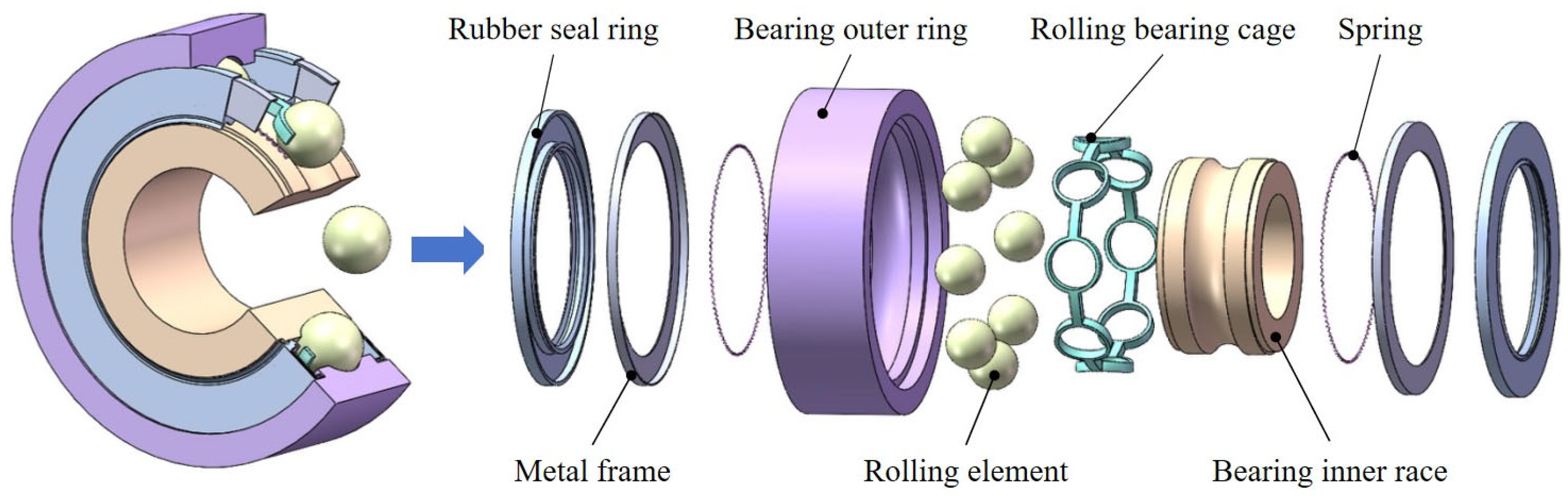
2.1. Geometric Models and Material Parameters Settings

2.1.1. Geometric Model

Figure 2 depicts the geometry assembly model of the high-speed ball bearing, which is composed of an inner ring, an outer ring, rolling elements, a cage, a rubber sealing ring, a spring and a metal frame.
For the convenience of operation, this text adopts the cyclic counterweight method, and only the 15° model of the radial lip seal is taken for finite element simulation analysis. Figure 3a presents the finite element simulation analysis model, and Figure 3b is an enlarged view of the radial lip seal structure.
As can be seen from Figure 3, the lip seal is mainly composed of a metal frame, a spring, a main lip and a secondary lip. The metal frame serves the supporting function, the spring provides the radial preload force for the main lip, the main lip performs the main sealing function, preventing the leakage of lubricating grease in the bearing cavity, and the auxiliary lip mainly serves the purpose of dust prevention. Therefore, this article mainly takes the contact pressure between the main lip of the lip seal and the inner ring, as well as the wear volume of the main lip, as optimization indicators. The main optimized structural parameters are P2, P3, P4, P10 and P11, and their corresponding structural parameters are shown in Table 1.

2.1.2. Material Parameters

Superelasticity refers to the ability of a material to withstand a large amount of elastic strain [27]. Nitrile Butadiene Rubber (NBR) is widely used as the material for rolling bearing sealing rings due to its excellent oil resistance, wear resistance, high elasticity and aging resistance [28]. The materials of the bearing sealing ring, metal frame and inner and outer rings of the bearing are NBR, SPCC and GCr15 in sequence. The mechanical behavior of the nonlinear hyperelastic material NBR is characterized by the Mooney–Rivlin model [25,27], and the strain energy density function of this model is [29]
W = C 10 I 2 3 + C 01 I 2 3 + 1 / d J 1 2
C 10 = E / 7.5 ,   C 01 = 0.025 C 10
In the formula, W represents the strain energy density per unit reference volume, C10 and C01 are material constants, I1 and I2 are the two principal invariants of the strain tensor, d is the reciprocal of the volume modulus, J is the ratio of the volume after deformation to that before deformation and E is the elastic modulus of rubber.
The elastic modulus E of rubber given by [30]
E = 15.75 + 2.15 H A / 100 H A
d = 1 2 μ / C 10 + C 01
In which HA denotes the Shore hardness of rubber materials and μ is Poisson’s ratio, taken as 0.29.
Table 2 presents the material parameters of the bearing.

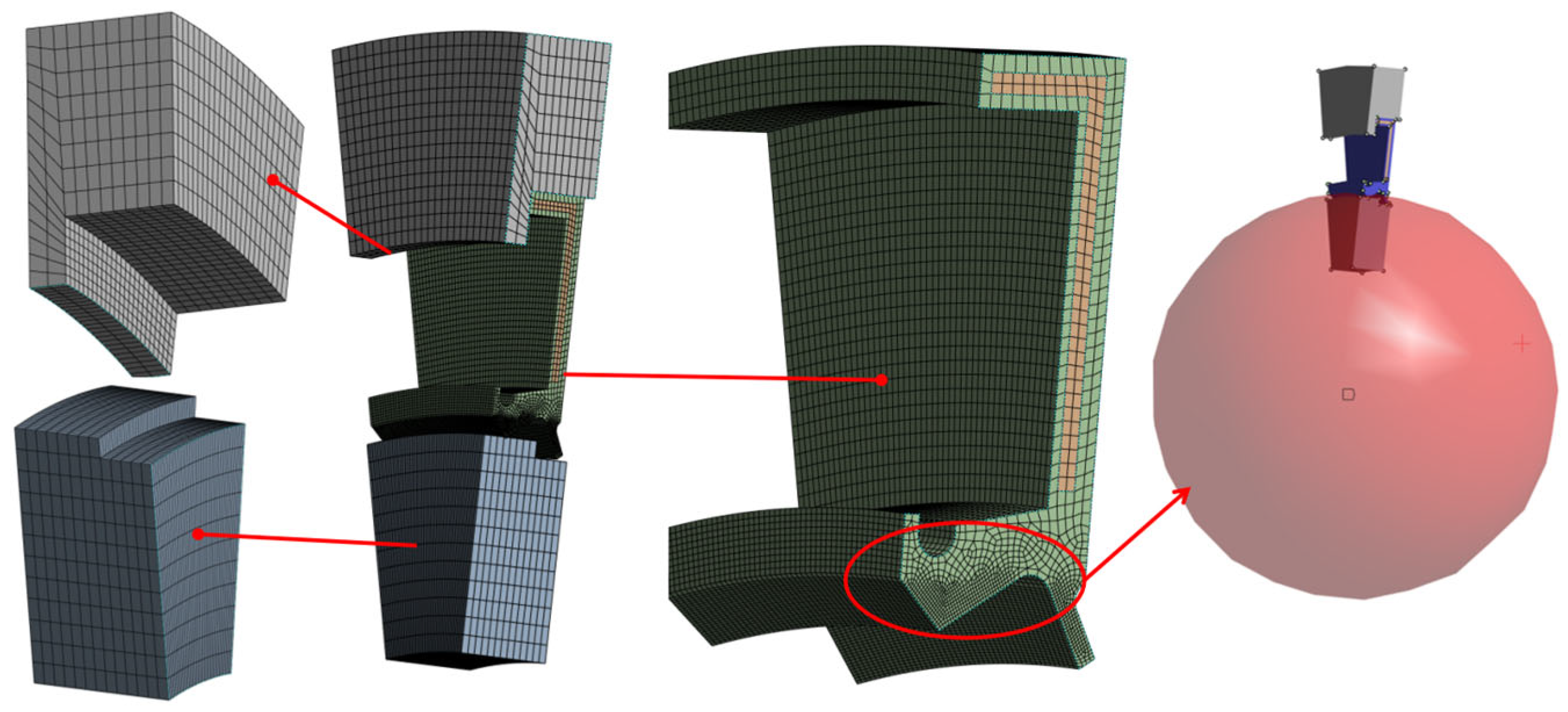
2.2. Mesh Generation

The inner and outer rings of the bearing have relatively regular shapes, so a hex-agonal mesh is used for division, and the mesh size is 0.1 mm. The rubber lip seal and the metal frame are the main analysis objects. The mesh of the two should be appropriately densified, with a size of 0.04 mm. The contact pressure generated between the inner ring and the main lip is a key factor in evaluating the quality of the sealing performance and is also the key analysis object in this paper. Hence, it is extremely necessary to refine the grid of the lip area. To avoid excessive differences in the mesh sizes of the transition zone, first, a spherical range with a radius of 4.2 mm is established with the center of the bearing as the center, and the mesh size of the rubber lip seal within this spherical range is set to 0.02 mm. Secondly, a spherical range with a radius of 4.1 mm is established, and the mesh size of the rubber lip seal within this spherical range is set to 0.01 mm; this is to further refine the lip mesh. Meanwhile, the outer surface of the inner ring in contact with the main lip should also undergo corresponding grid refinement treatment. Taking the 15° model as an example, the number of meshes after division is 52,633. Figure 4 shows the mesh diagram of the thermal–stress–wear coupled finite element model.
To ensure that simulation results are mesh-independent, this study verifies the model’s grid convergence. Figure 5 shows the variation law of the contact pressure and wear volume in the main lip contact area with the number of meshes of this 15° model. Figure 5 demonstrates that, when the number of meshes exceeds 52,500, the wear volume of the lip seal and the change in contact pressure tend to be stable. Therefore, in this paper, the number of meshes selected as 52,633 for simulation not only reduced the simulation error but also improved the calculation efficiency.

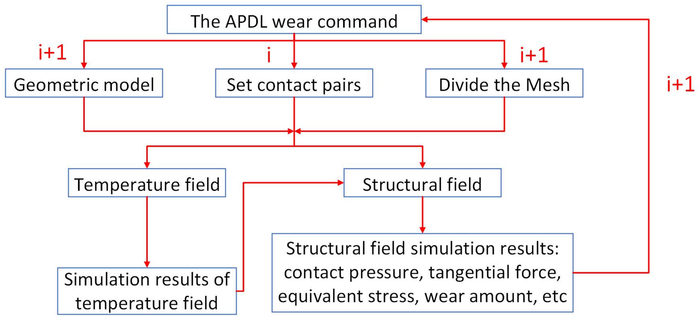
2.3. Add APDL Wear Program

Archard’s wear law links the volume loss of a material to the work performed by friction on the material’s surface. Archard’s law is usually [31]
V = K W τ H
where V is the total amount of material worn off the surface; W τ represents the work performed by the tangential surface force, H represents the hardness of the worn material and K is a dimensionless empirical constant.
For implementation in Rocky, this paper adopts the incremental form of the Archard formula:
V = C W τ
The APDL program regarding Archard wear is added to the contact pairs created for the main lip and inner ring. This Archard wear model moves the contact nodes in the normal direction of the contact according to the wear increment, enabling the repositioned contact nodes to undergo additional iterations to achieve convergence and proceed to the next sub-step iterative calculation until the entire model calculation is completed. The wear direction is dynamically defined by the contact penetration direction and determined in real time through the pseudo-contact normal vector of the contact unit. The incremental calculation adopts an explicit incremental format, which is the path integral of tangential work based on the frictional force within each incremental step.
Figure 6 shows the flowchart of the coupling of wear simulation with structural field and temperature field. As shown in Figure 6, the model is first meshed and contact pairs are set. After the settings are completed, the temperature field is simulated and analyzed, and the analysis results of the temperature field are imported into the structural field; the APDL program calculates the wear volume based on the feedback results from the structural field and updates the mesh and model, thus entering the next new cycle.

2.4. Boundary Condition Setting

2.4.1. Setting of Temperature Field Boundary Conditions

The change in environmental temperature affects the parameters of bearing materials, alters the distribution of structural stress in the lip seal and thereby affects the sealing performance of the lip seal [32]. Both the inner ring and the lip seal of the bearing have forced convection with the environment, whereas natural convection characterizes the heat transfer between the bearing outer ring and the environment. The thermal emissivity coefficient between all components within the bearing assembly is 0.77, whilst the thermal emissivity coefficient between the bearing and the external environment is 0.87 [33]. For high-speed ball bearings, the frictional power consumption generated between various internal parts during operation is the main cause of the temperature rise in the lip seal. Therefore, when conducting temperature field simulation of the bearing, it is necessary to consider the influence of the frictional power consumption between various parts of the bearing on it.
The calculation formula for friction power dissipation of a bearing [33] is
Q = 1.05 × 10 4 n M
where Q is the frictional power consumption of the bearing (W); n is the rotational speed of the bearing (r/min); and M is the frictional torque (N mm).
A dynamic model of the ball bearing was established using the ADAMS 2017 software. The dynamic analysis of the bearing was carried out under a rotational speed of 21,958 rpm, a radial load of 80 N and an axial load of 50 N, and the friction torque of the ball bearing was calculated. Figure 7 is a time-domain graph of the friction torque of the bearing. In order to reduce the influence caused by the unstable calculation results in the initial operation of the bearing, this paper selected the average value of the friction torque between 0.02 s and 0.20 s to calculate the friction power dissipation.
The calculated bearing friction power consumption was added to the steady-state thermal module of ANSYS in the form of internal heat generation to enhance the accuracy of the calculation results.

2.4.2. Setting of Boundary Conditions for Structural Field

We added fixed supports to the outer ring of the bearing to prevent it from moving. A remote displacement was added to the inner ring of the bearing to make it rotate only around the X-axis. Since the rotational speed of this inner ring of the bearing is as high as 150,000 rpm, in this paper, the phased addition of the rotational speed was achieved by dividing it into three different sub-steps, which made the simulation results more convergent. The rubber lip seal and the metal frame were set to be bound. The rubber lip seal had an interference contact with the inner ring of the bearing, and the friction coefficient was 0.2. The preload force of the spring was simulated by applying a normal force to the main lip of the lip seal. Figure 8 shows the setting graph of the boundary conditions for structural field.

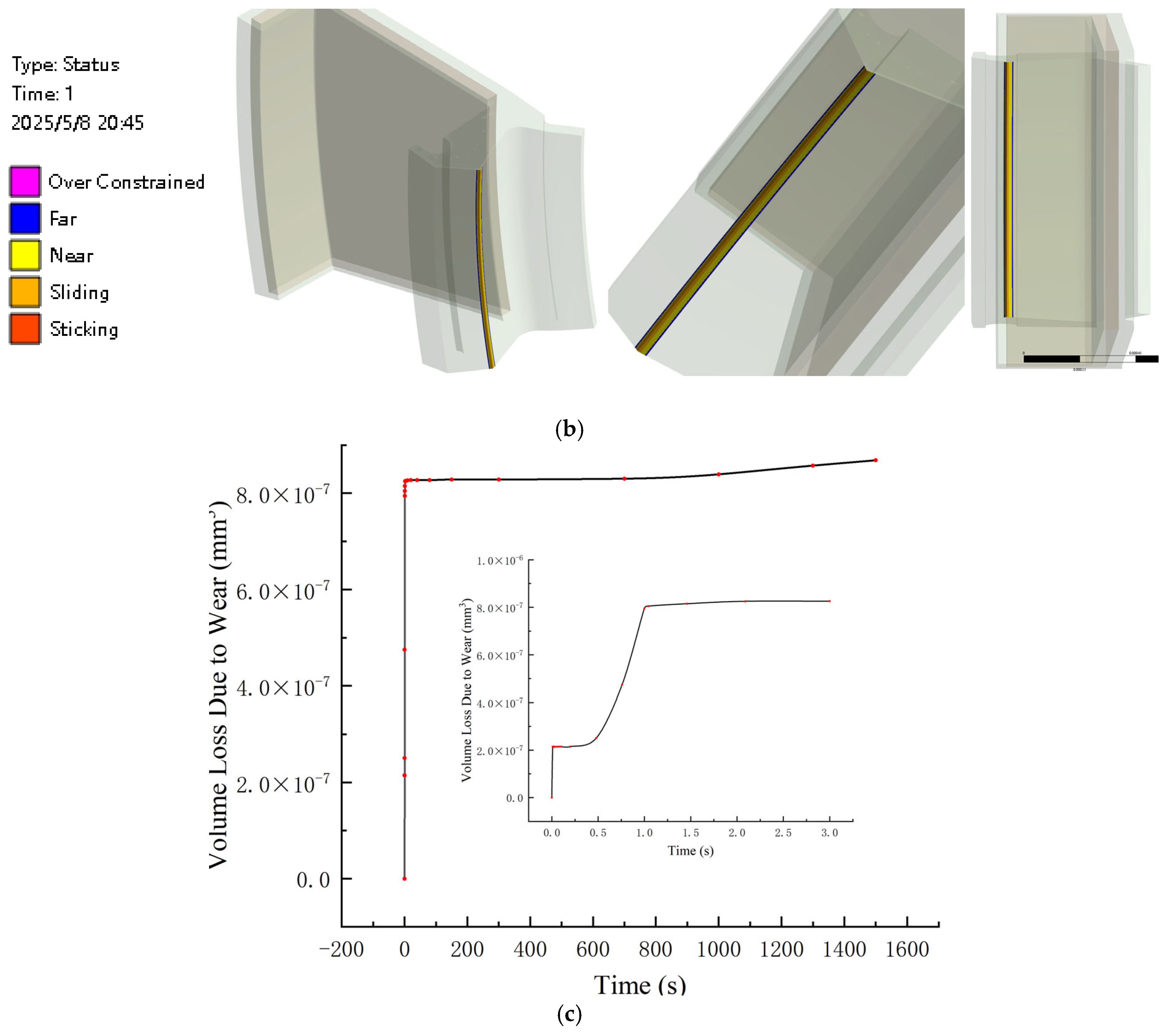
2.5. Finite Element Analysis Results of Thermal–Stress–Wear

The contact pressure between the main lip of the lip seal and the inner ring is the main factor contributing to the sealing effect of the lip seal. However, contact pressure and wear volume are a pair of contradictions. An increase in contact stress enhances the sealing performance, but it accelerates the wear of the sealing material, thereby leading to a decrease in contact pressure; the decrease in contact pressure, in turn, reduces the sealing effect. How to balance the relationship between the two to achieve the best sealing effect is the key to this study. Therefore, in this paper, the maximum contact pressure and the minimum wear volume were taken as indicators to measure the quality of the sealing performance, and through the response surface optimization method, the optimal values of each parameter for the seal performance were determined.

2.5.1. Simulation Results of the Temperature Field

Figure 9 shows the simulation results of the temperature field. Figure 9 shows that the contact area between the main lip and the inner ring has the highest temperature, which is 71.45 °C. The temperature decreases successively from the main lip to both sides, and the temperature in the upper part of the lip seal is relatively low. This is because the other areas of the lip seal are exposed to the air and dissipate heat through forced convection. However, the contact area between the inner ring and the main lip opening is wrapped by the sealing structure, and due to the existence of interference, the rubber material is subjected to a certain degree of compression, so the temperature in the contact area of the main lip opening of the lip seal is relatively high. The upper part of the lip seal is connected to the outer ring, the outer ring is fixed and has good heat conduction performance, so the temperature at the upper part of the lip seal is relatively low.

2.5.2. Simulation Results of the Structural Field

We imported the simulation results of the temperature field into the structural field and then carried out the simulation calculation of the structural field.
Figure 10a shows the distribution of contact pressure of the lip seal. It can be seen that the contact pressure is the highest at the end of the main lip, which is 0.79 MPa, and the contact pressure gradually decreases uniformly from the top of the lip opening to both sides. This is because the stress disturbance generated by interference fit is most significant at the end of the main lip and gradually decreases as it moves away from the end. Therefore, the contact pressure shows a distribution pattern that decreases successively from the end to both sides.
Figure 10b is the distribution graph of contact states. It can be seen that the contact states from the main lip end to both sides are sliding, near and far in sequence. This is because at a high speed of 150,000 rpm, the tip of the lip is subjected to the maximum radial pressure, causing the oil film to be extremely thin and resulting in direct friction between the solids; therefore, this area is in a sliding state. The area near the tip of the lip is subjected to mixed lubrication due to decreasing contact pressure, resulting in intermittent contact between the micro-convex body and the inner ring, ultimately putting the area in a near state. Due to the fluid dynamic pressure effect, full flow lubrication is formed at the edge of the lip, and the contact pressure approaches 0, so this area is in a far state.
Figure 10c shows the variation in the lip wear volume over time. It can be seen from Figure 10c that the wear volume of the lip seal rises rapidly from 0 to 1 s and then stabilizes. This is because the rotational speed of this bearing is as high as 150,000 rpm, and the rotational speed per second is as high as 25,000 r. Therefore, at the initial contact moment, The microscopic rough peaks are rapidly ground flat due to the extremely high number of cyclic shearing cycles, which causes the wear volume to increase rapidly within 0–1 s and then stabilize. Therefore, in order to improve the computational efficiency, we ultimately selected the simulation results within 0–1 s. As shown in Figure 10c, the wear volume remains almost unchanged from 0 to 0.4 s and rapidly increases to 7.94 × 10⁻⁷ mm3 from 0.4 to 1 s. This is because in the initial stage of 0–0.4 s, the lip seal and contact surface are in the running-in adaptation period, and the contact pressure distribution is not completely stable, resulting in a lower wear rate. Between 0.4 and 1 s, contact pressure and frictional heat accumulate to a certain extent, and the fatigue wear of the material intensifies, leading to an accelerated increase in wear volume. Due to the bearing’s rotational speed reaching up to 150,000 rpm, which is equivalent to 2500 r per second, the microscopic rough peaks in the contact area between the lip seal and the inner ring of the bearing are rapidly worn flat by the extremely high number of cyclic shearing cycles, resulting in the wear volume stabilizing after 1 s.

3. Response Surface Optimization

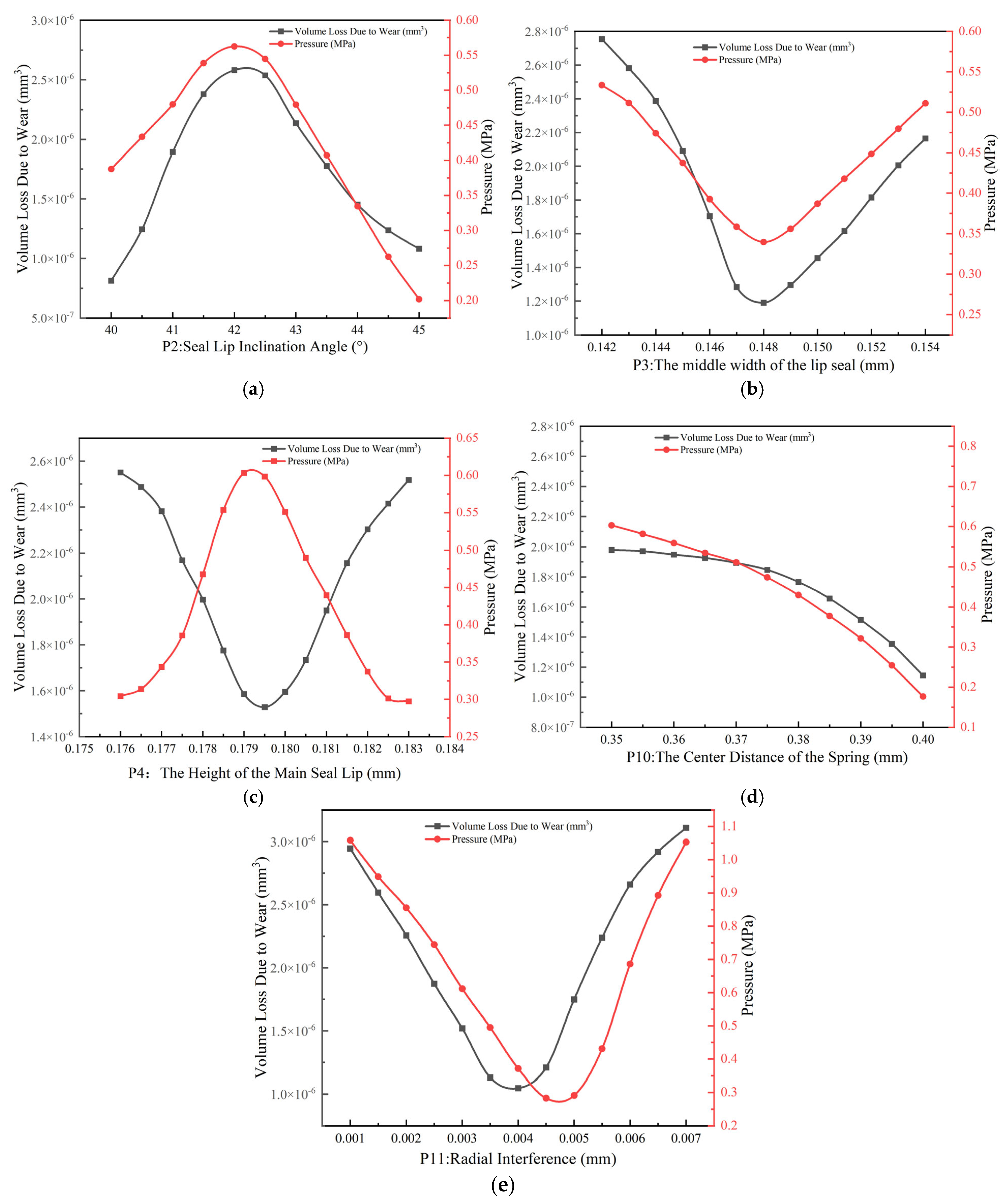
3.1. Determining the Optimization Range of the Response Surface

The response surface method (RSM) is a statistical technique that optimizes the target response by constructing an approximate function instead of repetitive modeling and screens the optimal parameter combination from potential schemes [34,35,36]. This article is based on the response surface optimization module of ANSYS Workbench software, using maximum contact pressure and minimum wear volume as indicators to measure the sealing performance; through analyzing the influence of the laws of the structural parameters of the sealing ring on the sealing performance, the range of optimization parameters is determined and the structural parameters of the sealing ring are optimized, in order to improve the reliability, durability and adaptability of the sealing ring.
In Figure 11a,b,d,e, the wear volume of the lip seal and the contact pressure exhibit similar variation tendencies. Conversely, in Figure 11c, these two parameters demonstrate opposing trends. This occurs because contact pressure is directly influenced by P4, whereas the wear volume of the lip seal is influenced by the combined effects of pressure, lubrication and material properties. In Figure 11c, as P4 increases, the contact pressure initially rises then decreases. Consequently, the grease viscosity follows an identical trend to that of the contact pressure. Higher grease viscosity impairs fluidity, causing the grease to be retained within the contact zone. This enhances lubrication performance in the contact region, resulting in reduced wear volume. Conversely, when viscosity decreases, wear volume increases.
Based on research experience, the weight of the contact pressure is greater than that of the wear volume. Therefore, the optimization range is determined by comparing the size of the ratio of the contact pressure to the wear volume within different parameter ranges. From Figure 11, we can see the influence of the laws of each factor on the sealing performance. According to the above judgment principles, the optimization ranges of the response surfaces of each parameter are selected, as shown in Table 3.

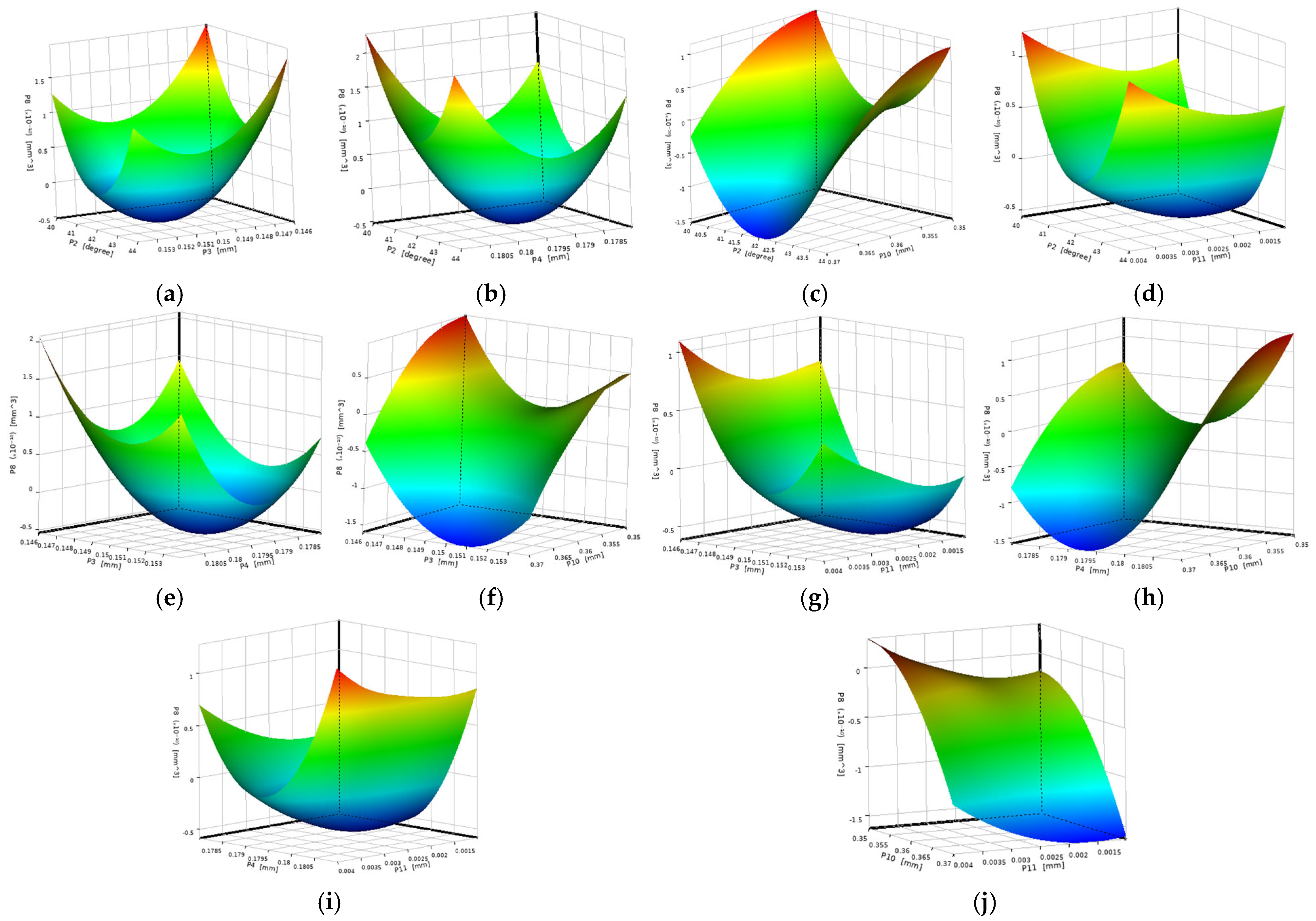
3.2. Optimal Design of Response Surface

The Latin Hypercube sampling method has the advantages of a small sample size, high accuracy, and uniform and independent distribution of sample points. The Kriging surrogate model has outstanding fitting ability and high accuracy [37,38]. Therefore, in this paper, the Latin Hypercube sampling method and the Krigng surrogate model were employed to conduct response surface optimization of the structural parameters of the lip seal. Figure 12 shows the contact pressure response surface diagrams, and Figure 13 shows the lip wear volume response surface diagrams.
The steeper the response surface is, the more significant the influence of the factors on the response value is. When the contour lines are similar to an ellipse, it indicates that the interaction between the two factors is significant; otherwise, it is not significant [39].
In Figure 12, the contour lines of response surfaces (a), (b) and (c) are similar to ellipses, indicating significant interactions between P2 and P3, P2 and P4, and P2 and P10. The response surfaces of (d), (e), (f), (g), (h), (i) and (j) are very steep, indicating that P2 and P11, P3 and P4, P3 and P10, P3 and P11, P4 and P10, P4 and P11, and P10 and P11 have a significant impact on contact pressure.
In Figure 13, the response surfaces of (a), (b), (c), (d), (e), (g) and (i) are steep and the contour lines are similar to ellipses, indicating significant interactions between P2 and P3, P2 and P4, P2 and P10, P2 and P11, P3 and P4, P3 and P11, and P4 and P11, respectively, and they have a significant impact on the volume of lip wear. The response surfaces of (f), (h) and (j) are very steep, indicating significant responses between P3 and P10, P4 and P10, and P10 and P11, and they have an impact on the volume of lip wear, but the interaction is not obvious.

3.3. Model Validation

In ANSYS, the structural parameters of the lip sealing ring were optimized using response surface methodology. To ensure the accuracy of the results, it is necessary to verify the accuracy of the response surface model. Figure 14 shows the goodness of fit of the model. From Figure 14, it can be seen that both the actual and predicted values fall on the 45° diagonal, indicating that the overall fitting effect of the model is good, with a certain degree of accuracy and reliability.

3.4. Multi-Objective Optimization Results

The genetic algorithm has strong global search ability and universality. Therefore, in this paper, the genetic algorithm was adopted to search for the optimal solution that satisfies the constraint conditions within the design space [40]. Table 4 shows the three candidate points obtained from the optimization of the response surface. It can be known from Table 4 point 3 had the smallest wear volume and highest contact pressure. Therefore, the structural parameters corresponding to candidate point 3 were selected as the optimized structural parameters of the lip seal.

4. Experimental Verification

The grease leakage rate of sealing rings is an indicator that measures the quality of sealing performance [41]. In this paper, the grease leakage rate of bearings was calculated by the weighing method. After the test, the lubricating grease that leaked from the bearing surface was wiped off, and the difference between the weight of the bearing after the test and the weight before the test was calculated. The ratio of the calculated difference to the weight of the bearing before the test was the grease leakage rate of the bearing.

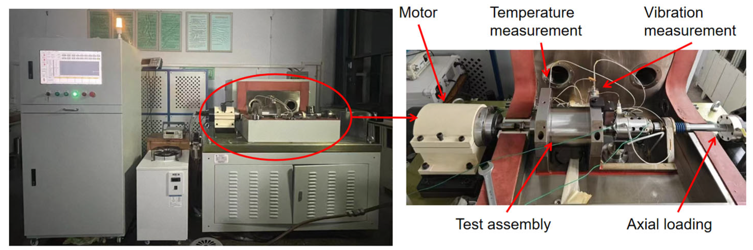
4.1. Experimental Instrument

Figure 15 shows the experimental scene of the high-speed bearing lubrication performance testing machine. The testing machine simulates the high-speed rotation condition of bearings through a motor drive system, and simulates the actual load experienced by bearings during operation through a load device. The measurement system monitors the operating parameters of bearings in real time through a multi-source sensor array and feeds them back to the control system, which controls the entire testing process.
The experiment was conducted at a speed of 150,000 rpm, with a radial load of 80 N and an axial load of 50 N. The grease content of the test bearing was 30%. We conducted tests on the lip seals before and after optimization, and the sealing performance was evaluated based on the leakage rate.

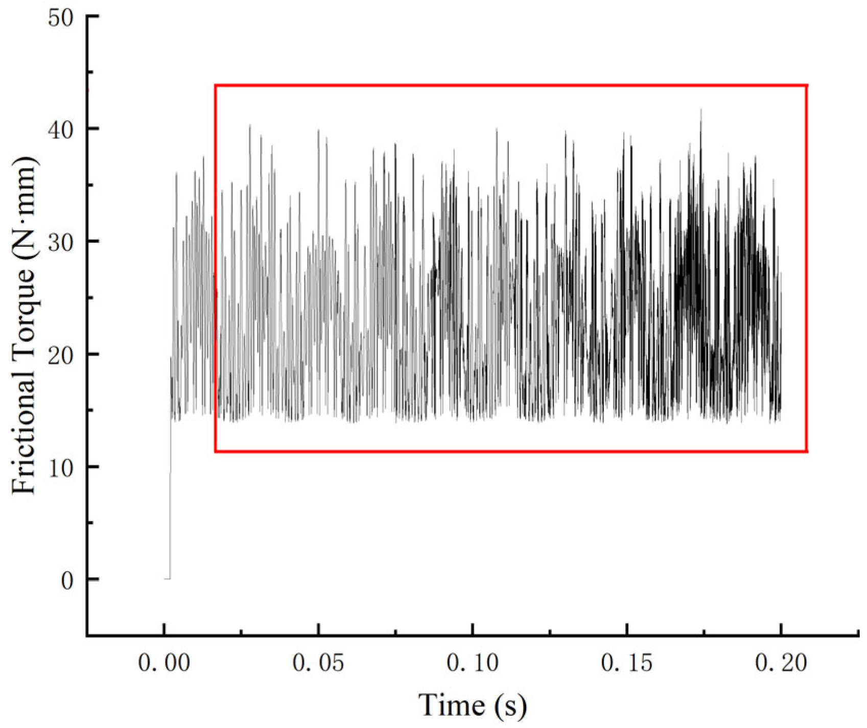
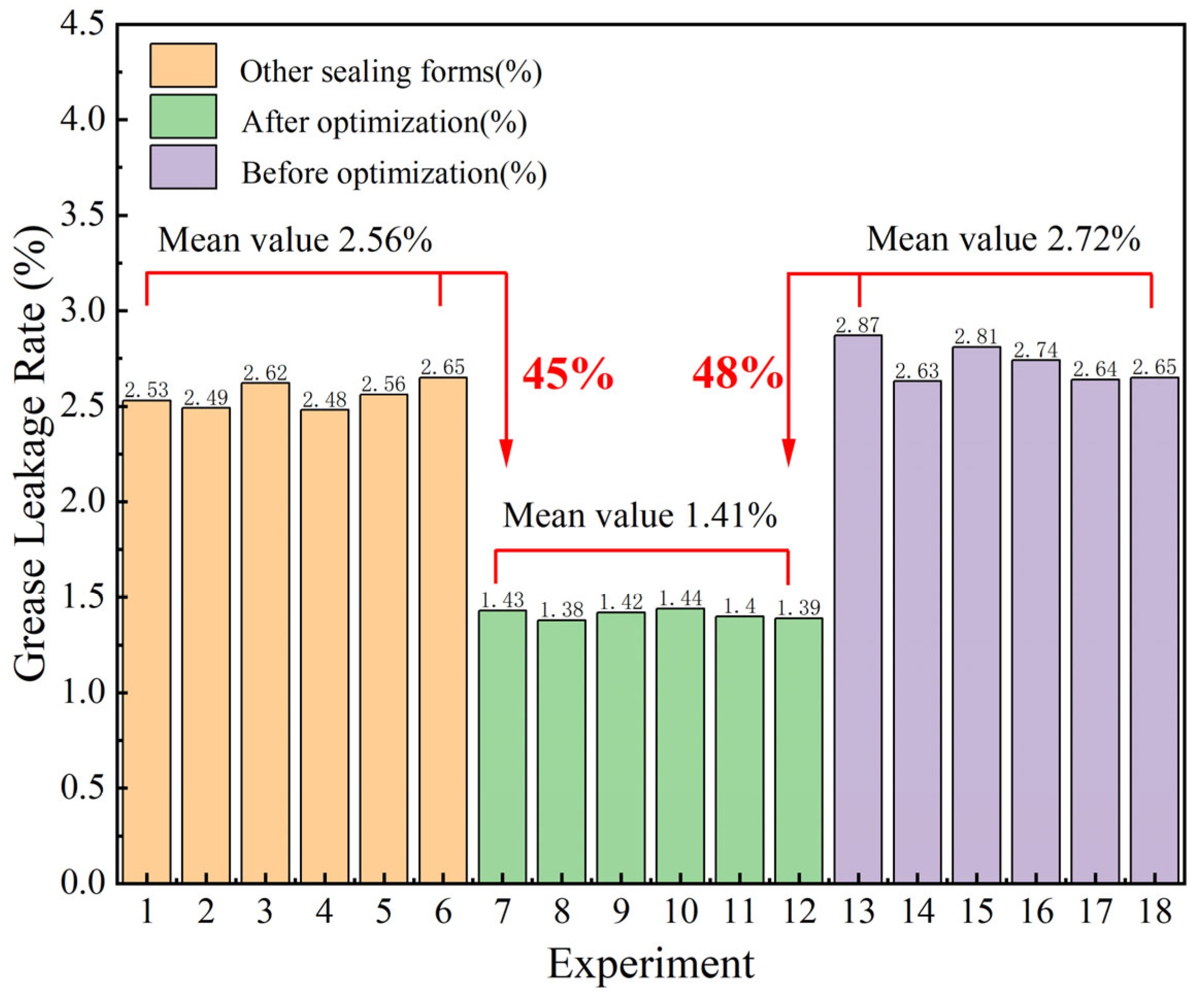
4.2. Results of the Experiment

Figure 16 shows the experimental results. To enhance the persuasiveness of the test, we conducted a grease leakage test on bearings of the same model but with different sealing structures available on the market and compared it with the grease leakage rates of the target bearings before and after optimization in this paper. To eliminate the influence of accidental factors on the test results and enhance the credibility of the test, each group of tests was repeated six times in this experiment, and the average of the six test results was taken as the test result to improve the accuracy of the test. According to Figure 16, the grease leakage rate of bearings of the same model but different sealing forms was 2.56%. Before optimization, the grease leakage rate of the lip seal was 2.72%, but after optimization, it was only 1.41%, which was 45% lower than the former and 48% lower than the latter. After optimization, the leakage rate of the lip seal significantly decreased, indicating that the finite element model and analysis method established in this paper for thermal–stress–misalignment are correct.

5. Results

This paper focuses on the sealing failure problem of double-lip seal for high-speed ball bearings used in unmanned aerial vehicles. By using ANSYS software, a coupled finite element model for thermal–stress–wear was established. Taking the contact pressure and volume loss due to wear as the indicators to measure the sealing performance, the influence law of the structural parameters of the lip seal on the sealing performance was analyzed, response surface optimization of the seal structural parameters was performed, and a comparative test was conducted on the lip seals before and after optimization. This research shows the following:
  • The simulation results of the coupled finite element model of thermal–stress–wear show that the contact pressure at the main lip of the sealing lip is the highest, which is 0.79 Mpa. The contact states of the lip seal from the main lip end to both sides are sliding, near and far, respectively. The wear volume of the lip seal when it reaches the stable stage of operation is 7.94 × 10⁻⁷ mm3.
  • Based on the ANSYS Workbench software response surface optimization module, it is concluded that the sealing performance of the bearing lip seal is optimal when the lip inclination angle is 41.68°, the middle width of the lip seal is 0.153 mm, the height of the main seal lip is 0.179 mm, the center distance of the spring is 0.3698 mm and the radial interference fit is 0.0034 mm.
  • A comparative test was conducted on the lip seal before and after optimization, and it was found that the grease leakage rate of the lip seal after optimization decreased by 48% compared to that before optimization, indicating that the thermal–stress–wear coupled finite element model established in this paper is correct.

Author Contributions

Conceptualization, H.W. and Y.Y.; methodology, H.W. and Y.Y.; software, Y.C.; validation, L.L. and C.L.; formal analysis, H.W.; investigation, L.L.; resources, C.L.; data curation, Y.Y.; writing—original draft preparation, Y.C.; writing—review and editing, H.W.; visualization, Y.Y.; supervision, L.L.; project administration, C.L.; funding acquisition, H.W. All authors have read and agreed to the published version of the manuscript.

Funding

This research was funded by the Key R&D Plan of Ningbo City (2023Z006) and Ningbo City Unveiled Project (2023T016).

Data Availability Statement

The data used to support the findings of this study are available from the corresponding author upon request.

Conflicts of Interest

Author Lina Lou was employed by the company Ningbo Great Group Co., Ltd. Author Chang Li was employed by the company Shandong Chaoyang Bearing Co., Ltd. The remaining authors declare that this research was conducted in the absence of any commercial or financial relationships that could be construed as potential conflicts of interest.

References

  1. Chen, J.; Du, C.; Zhang, Y.; Han, P.; Wei, W. A Clustering-Based Coverage Path Planning Method for Autonomous Het-erogeneous UAVs. IEEE Trans. Intell. Transp. Syst. 2022, 23, 25546–25556. [Google Scholar] [CrossRef]
  2. Qi, J. The unmanned aerial vehicle industry is booming, the low-altitude economy has been integrated into various industries. China Secur. J. 2025. (In Chinese) [Google Scholar] [CrossRef]
  3. Qin, Y.; Jia, S. Exploration of the application of surveying and mapping technology in the planning and management of exhibition venues. China Conf. Exhib. 2025, 39–41. (In Chinese) [Google Scholar] [CrossRef]
  4. Tognon, M.; Alami, R. Physical Human-Robot Interaction With a Tethered Aerial Vehicle: Application to a Force-Based Human Guiding Problem. IEEE Trans. Robot. 2021, 37, 723–734. [Google Scholar] [CrossRef]
  5. Brown, M.W. Seals and Sealing Handbook, 3rd ed.; Elsevier: London, UK, 1990. [Google Scholar]
  6. Shen, D. Deterministic Modeling of Rotary Lip Seal with Microasperities on the Shaft Surface; Georigia Institute Technolohy: Atlanta, GA, USA, 2005. [Google Scholar]
  7. Dong, X.; Song, J. Simulation study of lip seal considering rotating shaft vibration. Lubr. Eng. 2025, 1–10. (In Chinese) [Google Scholar]
  8. Jagger, E.T. Rotary shaft seals: The sealing mechanism of synthetic rubber seals running at atmospheric pressure. Proc. Inst. Mech. Eng. 1957, 171, 597–616. [Google Scholar] [CrossRef]
  9. Jagger, E.T. Study of the lubrication of synthetic rubber rotary shaft seals. Proc. Inst. Mech. Eng. Conf. Lubr. Wear 1957, 409, 409–415. [Google Scholar]
  10. Jagger, E.T.; Walker, P.S. Further studies of the lubrication of synthetic rubber rotary shaft seals. Proc. Inst. Mech. Eng. 1966, 181, 191–204. [Google Scholar] [CrossRef]
  11. Poll, G.; Gabelli, A. Formation of lubricant film in rotary sealing contacts, Part II-A new measuring principle for lubricant film thickness. ASME J. Tribol. 1992, 114, 290–297. [Google Scholar] [CrossRef]
  12. Poll, G.; Gabelli, A.; Binnington, P.G.; Qu, J. Dynamic mapping of rotary lip seal lubricant films by fluorescent image processing. In Proceedings of the 13th BHRA International Conference on Fluid Sealing, Brugge, Belgium, 7–9 April 1992; pp. 55–77. [Google Scholar]
  13. Salant, R.F.; Flaherty, A.L. Elastohydrodynamic analysis of reverse pumping in rotary lip seals with microundulations. ASME J. Tribol. 1994, 116, 56–62. [Google Scholar] [CrossRef]
  14. Salant, R.F.; Flaherty, A.L. Elastohydrodynamic analysis of reverse pumping in rotary lip seals with micro asperities. ASME J. Tribol. 1995, 117, 53–59. [Google Scholar] [CrossRef]
  15. Salant, R.F.; Shen, D.W. Hydrodynamic effects of shaft surface roughness on rotary lip seal behaviour. Seal. Technol. 2003, 7, 5–9. [Google Scholar] [CrossRef]
  16. Wen, S.Z. Progress and Thoughts on Lubrication Theory Research. Tribology 2007, 6, 497–503. [Google Scholar] [CrossRef]
  17. Zhao, S.Q.; Wang, F.R. Optimal design and experimental verification of sealing structure of hub bearing units. Bearing 2025, 02, 39–45. [Google Scholar] [CrossRef]
  18. Pan, J.; Zou, G.F. Numerical analysis and limit condition study of temperature and deformation fields of high-speed bearing cavity magnetic seals. J. Mech. Electr. Eng. 2025, 42, 667–676. [Google Scholar] [CrossRef]
  19. Ma, L.B.; Ma, C.B. Sealing Performance of Lip Seal Ring in Eccentric State of Spherical Roller Bearing. Lubr. Eng. 2025, 1–9. (In Chinese) [Google Scholar]
  20. Wang, J.; Hao, H. The sealing performance of PTFE 0-rings at low temperature. J. Phys. Conf. Ser. 2024, 2842, 012014. [Google Scholar] [CrossRef]
  21. Wei, J.; Liu, C.; Guo, F.; Tian, J. Effect of angle eccentricity on lip seal performance of helicopter gearbox. Tribol. Int. 2025, 209, 110676. [Google Scholar] [CrossRef]
  22. Chen, S.S.; Guo, F. An improved mixed lubrication model for revealing the mechanism of high speed and frictional heat on sealing performance. Tribol. Int. 2024, 191, 109147. [Google Scholar] [CrossRef]
  23. Jing, S.; Mu, A. Finite-element analysis and structure optimization of X-O composite seal of cone bit. Adv. Mech. Eng. 2020, 12, 1687814020918686. [Google Scholar] [CrossRef]
  24. Li, X.; Peng, G.L. Prediction of seal wear with thermal–structural coupled finite element method. Finite Elem. Anal. Des. 2014, 83, 10–21. [Google Scholar] [CrossRef]
  25. Zhang, S.; Cui, Y.C. Thermal-stress-wear coupled characteristics of oil seal in airframe rod end-bearing. Tribol. Int. 2021, 163, 107132. [Google Scholar] [CrossRef]
  26. Bekesi, N.; Varadi, K. Wear simulation of a reciprocating seal by global remeshing. Period. Polytech. Mech. Eng. 2010, 54, 71–75. [Google Scholar] [CrossRef]
  27. Qiao, X.K.; Yang, M. An analytical model for stress distribution of NBR O-ring during dynamic hydrogen permeation. Int. J. Hydrog. Energy 2025, 109, 164–173. [Google Scholar] [CrossRef]
  28. Zhang, S.L.; Qian, Z.H. Optimal Design and Analysis on Sealing Rings of Hub Bearings. Beraing 2020, 11, 6–11. [Google Scholar] [CrossRef]
  29. Mooney, M. A theory of larhe elastic deformation. J. Appl. Phys. 1940, 11, 582–592. [Google Scholar] [CrossRef]
  30. Wang, W.; Deng, T.; Zhao, S.G. Determination of material constants in rubber Mooney-Rinlin model. Spec. Purp. Rubber Prod. 2004, 25, 8–10. [Google Scholar] [CrossRef]
  31. Qiu; Potapov; Song; Nordell, L. Prediction of wear of mill lifters using discrete ele-mentmethod. In Proceedings of the SAG Conference Proceedings, Vancouver, BC, Canada, 30 September–3 October 2001. [Google Scholar]
  32. Huo, J.J.; Gao, F. Medium Parameters Effect on Sealing Performance of Lip Seal Ring. Coal Mine Mach 2018, 39, 58–62. [Google Scholar] [CrossRef]
  33. Dai, Y.B. Research on Stress-Temperature Coupling Properties for Bearing Assembly of Control Momentum Gyroscope; Hennan University of Science and Technology: Luoyang, China, 2016. (In Chinese) [Google Scholar]
  34. Wang, J.Y.; Wang, L. A novel waste heat-driven methane reforming membrane reactor and parametric optimization study combining CFD simulation and response surface methodology. Case Stud. Therm. Eng. 2025, 70, 106111. [Google Scholar] [CrossRef]
  35. Feng, J.J.; Liu, B.X. Reliability Optimization Design of Hydrofoil Based on Response Surface Model. Chin. J. Hydrodyn. 2025, 40, 306–316. [Google Scholar] [CrossRef]
  36. Usman, A.; Sutanto, M.H.; Napiah, M.B.; Yaro, N.S.A. Response Surface Methodology Optimization in Asphalt Mixtures: A Review [Internet]. In Response Surface Methodology Optimization in Asphalt Mixtures: A Review; IntechOpen: London, UK, 2021. [Google Scholar] [CrossRef]
  37. Chen, Y.T.; Xia, T.Y. The optimization method of underground powerhouse support based on LHS-SSA-BPNN. Water Resour. Power 2025, 6, 162–166. (In Chinese) [Google Scholar]
  38. Yang, X.; Zhang, Y.; Wang, T.; Zhang, H. An active learning reliability method combining population Monte Carlo and Kriging model for small failure probability. Structures 2024, 70, 107621. [Google Scholar] [CrossRef]
  39. Zhao, H.G.; Sun, W.H. Effect of Laser Cutting of Oak Wood Based on Response Surface Methodology. Sci. Silvae Sin. 2025, 1–10. (In Chinese) [Google Scholar]
  40. Wang, H.; Yue, Y.; Cui, Y.; Qiu, X.; Li, C. Sealing Performance Analysis of Lip Seal Ring for High-Speed Micro Bearing. Lubricants 2024, 12, 442. [Google Scholar] [CrossRef]
  41. Liu, S.X. Sealing performance test of sealed bearing. Beraing 1992, 41–44+61. [Google Scholar] [CrossRef]
Figure 1. Research methodology framework.
Lubricants 13 00343 g001
Figure 2. Bearing geometric model.
Lubricants 13 00343 g002
Figure 3. Radial lip seal configuration schematic. (a) Finite element simulation analysis model. (b) Enlarged view of the radial lip seal structure.
Lubricants 13 00343 g003
Figure 4. Lip seal mesh generation.
Lubricants 13 00343 g004
Figure 5. Mesh independence verification.
Lubricants 13 00343 g005
Figure 6. Finite element wear model simulation flowchart.
Lubricants 13 00343 g006
Figure 7. Time-domain graph of friction torque.
Lubricants 13 00343 g007
Figure 8. Setting of structural field boundary conditions.
Lubricants 13 00343 g008
Figure 9. Filled contour plot of simulated temperature.
Lubricants 13 00343 g009
Figure 10. Simulation results of the structural field. (a) Contact pressure distribution of the main lip of the lip seal. (b) The contact state of the sealing ring lip. (c) Wear volume of the main lip.
Lubricants 13 00343 g010aLubricants 13 00343 g010b
Figure 11. The influence of various factors on sealing performance. (a) The inclination angle of the lip seal. (b) The middle width of the lip seal. (c) The height of the main seal lip. (d) The center distance of the spring. (e) Radial interference.
Lubricants 13 00343 g011
Figure 12. Contact pressure. (a) P2 and P3; (b) P2 and P4; (c) P2 and P10; (d) P2 and P11; (e) P3 and P4; (f) P3 and P10; (g) P3 and P11; (h) P4 and P10; (i) P4 and P11; (j) P10 and P11.
Lubricants 13 00343 g012
Figure 13. Volume loss due to wear. (a) P2 and P3; (b) P2 and P4; (c) P2 and P10; (d) P2 and P11; (e) P3 and P4; (f) P3 and P10; (g) P3 and P11; (h) P4 and P10; (i) P4 and P11; (j) P10 and P11.
Lubricants 13 00343 g013
Figure 14. Goodness of fit.
Lubricants 13 00343 g014
Figure 15. High-speed bearing lubrication performance testing machine.
Lubricants 13 00343 g015
Figure 16. Experimental result chart.
Lubricants 13 00343 g016
Table 1. Initial structural parameters of the lip seal.
ParametersValue
P2: Seal lip inclination angle40–45°
P3: The middle width of the lip seal0.144–0.154 mm
P4: The heigh of the main seal lip0.177–0.182 mm
P10: The center distance of the spring0.35–0.40 mm
P11: Radial interference0.001–0.006 mm
Table 2. Material parameters of bearing.
MaterialPoisson’s RationDensity (g/cm3)Young’s Modulus (MPa)Isotropic Thermal Conductivity (W/(m·k))Coefficient of Thermal Expansion (/°C)
SPCC0.287.852 × 105551.12 × 10−6
GCr150.297.81219351.25 × 10−6
NBR0.490.987.80.2180 × 10−6
Table 3. Design of the range of variable values.
FactorLevel
Initial ValueLower BoundUpper Bound
P2: The inclination angle of the lip seal43°40°44°
P3: The middle width of the lip seal0.148 mm0.146 mm0.154 mm
P4: The height of the main seal lip0.178 mm0.178 mm0.181 mm
P10: The center distance of the spring0.36 mm0.35 mm0.37 mm
P11: Radial interference0.001 mm0.001 mm0.004 mm
Table 4. Optimize candidate points.
NameP2
(°)
P3
(mm)
P4
(mm)
P10
(mm)
P11
(mm)
P8 (mm3)P9 (MPa)
Parameter
Value
Variation
from
Reference
Parameter
Value
Variation
from
Reference
Candidate Point 141.560.1520.1790.3700.00351.18 × 10−103.14%0.654−1.16%
Candidate Point 141.800.1530.1790.36980.00341.16 × 10−101.66%0.655−0.98%
Candidate Point 141.680.1530.1790.36980.00341.14 × 10−100.00%0.6610.00%
Disclaimer/Publisher’s Note: The statements, opinions and data contained in all publications are solely those of the individual author(s) and contributor(s) and not of MDPI and/or the editor(s). MDPI and/or the editor(s) disclaim responsibility for any injury to people or property resulting from any ideas, methods, instructions or products referred to in the content.

