Abstract
In order to improve the lubrication efficiency in the bearing cavity, this study establishes a simulation model of the fluid domain of the bearing cavity based on the computational fluid dynamics (CFD) method and systematically studies the flow characteristics of the lubricant and its lubrication mechanism in the high-speed rotary bearing. In the process of high-speed bearing operation, the lubricant is subject to the combined effect of centrifugal force and contact pressure, gradually spreads to both sides of the steel ball, and forms a stable oil film after injection from the nozzle. However, due to the influence of high pressure distribution in the contact area, the actual formation of the oil film coverage is relatively limited. In order to further optimize the lubrication effect, this study focuses on investigating the influence law of different injection speeds and rotational speeds on the bearing air curtain effect. The results of the study show that when the air curtain effect is enhanced, there will be significant shear interference on the trajectory of the lubricant, which is manifested in the phenomenon of “buckling” at the end of the lubricant, thus reducing the lubrication efficiency. To address this problem, this study innovatively proposes the air curtain obstruction coefficient K as a quantitative evaluation index, and through numerical simulation, it is found that the lubricant can effectively overcome the air curtain obstruction and achieve a better lubrication coverage when the value of K is reduced to below 0.4. Based on this finding, the study further confirmed that the lubrication efficiency of bearings can be significantly improved under different operating conditions by rationally regulating the injection rate.
1. Introduction
Lubrication directly affects bearings’ service performance and life, and oil injection lubrication, with its precise control, high efficiency, energy saving, and other advantages, is widely used in high-speed rolling bearing lubrication. In the bearing oil injection lubrication system, the lubricant in the process of flowing through the internal clearance of the bearing will be subject to the rolling body and the cage of the agitation and centrifugal force, the bearing cavity of the air to form a two-phase flow of oil–airflow form, which directly determines the distribution of the lubricant in the bearing cavity, as well as on the distribution of heat, the cooling effect, and the ability to regulate.
Wen, B. [1] established a two-phase flow model for angular contact bearings and investigated the distribution characteristics of lubricant in the bearing cavity under different nozzle angles and heights, optimized the nozzle position by using the response surface method, and found that the nozzle height has negligible effect on the spherical surface, while the effect on the cage guiding surface is significant. Meanwhile, both spherical and cage guiding surfaces are significantly affected by the nozzle angle. Wu, M. [2] found that the oil–gas distribution from multipoint oil injection is more uniform compared to that of single-point injection. In the studies by Hu, J. [3] and Zhang, R. [4], the distribution characteristics of parameters such as the oil–gas volume fraction, velocity, and pressure within the bearing chamber were systematically investigated. By analyzing the effects of injection velocity and bearing rotational speed on the oil–gas flow and stirring torque, this study further explored methods for determining the optimal oil injection parameters with the aim of identifying the most effective injection conditions. Lu, P. [5] used the Hilbert–Huang transform (HHT) to analyze the spectra of the bearing cavity pressure signal and establish the correlation between the energy index k and the flow state. The effects of operating conditions and lubricant physical properties on the flow state are discussed. It is found that with the increase in the oil inlet and the decrease in pumping speed, the flow pattern changes from uniform flow to stratified flow, and the k value moves from the high-frequency band to the low-frequency band. At the same lubricant flow rate, as the lubricant density increases, the k-value moves from low frequency to high frequency, and the oil film on the wall surface becomes thinner. Bao, H. [6] used the coupled liquid level setting volume (CLSVOF) method to track the oil–gas two-phase flow inside ball bearings and adopted ring-under lubrication to study the effects of rotational speed, inlet velocity, and the size of the oil supply hole under the inner ring on the oil fraction inside ball bearings. Gao W. [7] used numerical methods to track the oil distribution inside cylindrical roller bearings lubricated along the circumference and radial direction, respectively. The results show that the oil distribution along the circumference is periodic with the number of under-race nozzles, and that higher rotational speeds and lower flow rates reduce the fluctuations. Lu, F. X. [8] applied thermo-elastohydrodynamic lubrication theory and computational fluid dynamics (CFD) methods to simulate and analyze the lubrication and geometric parameters of the bearing under various operating conditions. The study identified the optimal oil injection velocity and nozzle positioning, thereby optimizing bearing performance. Liu, J. [9] analyzed the relative motion between the steel balls and the cage using a combined dynamic approach. Based on FLUENT 2022 simulations, the study investigated the impact of the pocket gap on the oil–gas distribution within the bearing chamber. The results revealed that pressure variations occur abruptly in the contact region between the steel balls and the inner ring, while the pocket gap has a minimal effect on the overall lubrication within the chamber. Zhang, J. J. [10] investigated the rolling plain bearing oil–air two-phase flow (OATPF) based on CFD fluid–solid-coupled modeling using VOF method and sliding mesh. By comparing two design options, an optimized solution was derived, and this revealed the significant effects of rotational speed, oil flow rate, viscosity, ratio, and temperature on the lubrication performance. The results show that the oil inside the bearing is not uniformly distributed, with the lowest oil volume fraction upstream of the nozzle and gradually increasing from the inside to the outside, while the oil storage ratio increases with the increase in crude oil viscosity. The study proposes a new oil volume prediction method to provide reference for bearing design. Bei, Y. [11] established a high-precision model to study the airflow pattern and lubrication performance in the bearing cavity under different oil and gas supply methods. The oil–gas interface is tracked by the coupling technique of the level-set function and VOF method, and the migration and diffusion process of oil droplets in the bearing cavity is obtained. Jiang, L. [12] simulated the oil–gas two-phase flow inside an angular contact ball bearing by considering the structure of the oil transfer section, the oil groove under the ring, and the oil holes, and found that the degree of lubricant diffusion decreases sequentially on the outer ring, cage, ball, and inner ring, and that the average oil volume fraction varies monotonically with the speed of the inner ring, the volume of the oil injection, and the oil supply temperature. In the study of Gao, S. [13], based on the computational fluid dynamics (CFD) method, the fluid domain model of the same type of rolling bearings under different lubrication conditions was established. The transient flow fields of rolling bearings with oil injection lubrication in a tester and with splash lubrication in a planetary gearbox are simulated. The gas–oil transient distributions of rolling bearings in the two types of lubrication were analyzed. Ge, L. [14] proposed a new method to guide more oil into the bearing raceway by adding groove structures to the non-contact area on the inner ring surface of the bearing. Then, through numerical simulation, the oil flow behavior on the inner ring surface of the bearing was studied. The results showed that, compared with the traditional structure, the axial oil flow on the groove inner ring surface was enhanced, and more oil accumulated in the key lubrication areas inside the bearing cavity. Liu, J. [15] investigates the gas–oil two-phase flow of oil-injected lubricated ball bearings based on CFD fluid–solid coupling modeling, using the VOF method. The analysis shows that oil flow rate, viscosity, nozzle angle, and number significantly affect the lubrication characteristics. It is found that the oil distribution inside the bearing is uneven, the oil volume fraction (OVF) near the upstream of the nozzle is the smallest, and the average OVF and oil passage rate decreases with the increase in rotational speed and viscosity. The study provides guidance for improving gearbox bearing lubrication. Zhu, W. [16] used FLUENT to simulate the flow field of two types of double-row tapered roller bearings, with the flanges positioned on the inner and outer races, respectively. The study analyzed the lubrication oil flow characteristics within the bearing chamber under both oil-starved and non-oil-starved conditions. The results showed that the outer race flange effectively prevented the oil film from being ejected from the bearing chamber, thereby maintaining better lubrication performance. Gong, P. [17] used angular contact ball bearings with two semi-inner rings as carriers and analyzed the characteristics of two-phase flow of oil and air inside ball bearings based on the volume of fluid (VOF) method and standard k-ε turbulence model. The internal pressure field distribution, streamline distribution, and other flow characteristics of the bearings were determined for different radial working clearances, cavity clearances, and guide clearances.
However, the air curtain effect of bearings has a significant impact on bearing lubrication performance. Although there has been some studies on the air curtain effect of bearings, existing findings have some shortcomings in practical applications. Specifically, existing studies have primarily focused on the influence of single factors (nozzle structure, rotational speed) on the air curtain effect, whereas practical engineering applications require consideration of the combined effects of multiple factors. Based on this, this paper examines the coupled effect of bearing rotational speed and spray velocity on the air curtain effect and introduces the parameter of air curtain blocking coefficient. This has important implications for enhancing bearing spray lubrication efficiency and extending bearing service life. certain guiding significance for the practical application of oil injection lubrication.
On the distribution of lubricant in bearings and the effect of increasing speeds, the present study analyzes this more comprehensively than previous work under different rotational speed conditions, along with the volume distribution of oil in each section of the bearing.
2. Numerical Simulation Model and Boundary Conditions
2.1. Mathematical Models
2.1.1. VOF Model
The volume of fluid (VOF) model, created by Hirt and Nichols in 1981, is numerically stable, converges well, and shows good accuracy for complex fluid dynamics and heat transfer problems. Particularly suitable for dealing with interfaces between liquids and gases or liquids and liquids, it is capable of accurately tracking and characterizing the shape and location of fluid interfaces.
The volume fraction of each phase under oil–gas mixing is described by quoting the phase function φ. Letting air be the first phase, it can be characterized by calculating the volume fraction of air in the cell as φair; similarly, the volume fraction φoil of the oil phase can be used to describe the distribution of the lubricant in the cell. The two-phase volume fraction satisfies the following equation [17]:
When φoil = 0, it indicates a cell without oil, while when φoil = 1, it indicates a cell filled with oil. When 0 < φoil < 1, it indicates the interface between the oil phase and the gas phase. Thus, φoil is defined as follows:
With the VOF method, it is only computationally necessary to solve a single momentum equation over the entire fluid domain, and the resulting variable and property field (velocity field) are shared by both phases.
where ρoil is the density of the oil, v is the velocity vector, and Sαoil is the mass source term, which is 0 for the VOF method, indicating that there is no cross-interfacial mass transfer [18,19]. moa is the mass transport rate per unit volume from the oil phase to the gas phase, kg/m3·s, and mao is the mass transport rate per unit volume from the gas phase to the oil phase, kg/m3·s.
The equivalent density and dynamic viscosity of the oil and gas phases can be expressed as follows:
where ρair is the air density, μair is the aerodynamic viscosity, and μoil is the dynamic viscosity of the lubricant.
2.1.2. RNG k-ε Turbulence Model
The simulation results using the RNG model are generally good for bearings under high-speed rotation, and the oil–gas two-phase flow cannot be considered as laminar. Since the RNG k-ε turbulence model uses the “Renormalization Group” (RNG) method based on the instantaneous Navier–Stokes equations, it accounts for the effects of vortex-induced turbulence, as well as factors such as high strain rates and large curvature overflow. Therefore, it can improve the accuracy of simulations under high-speed swirling conditions [20]. The basic equations are as follows [21]:
Turbulent kinetic energy equation:
Turbulent dissipation rate equation:
where k is the turbulent kinetic energy; ε is the turbulent dissipation rate; ui is the time-averaged velocity, i = 1, 2, 3; μeff is the effective kinetic viscosity; μt is the turbulent viscosity; and the constant terms are as follows: C1ε = 1.2, C2ε = 1.68, Cμ = 0.0845, αk = αε = 1.39, η0 = 4.377, β = 0.012.
2.2. Geometric and Mesh Models
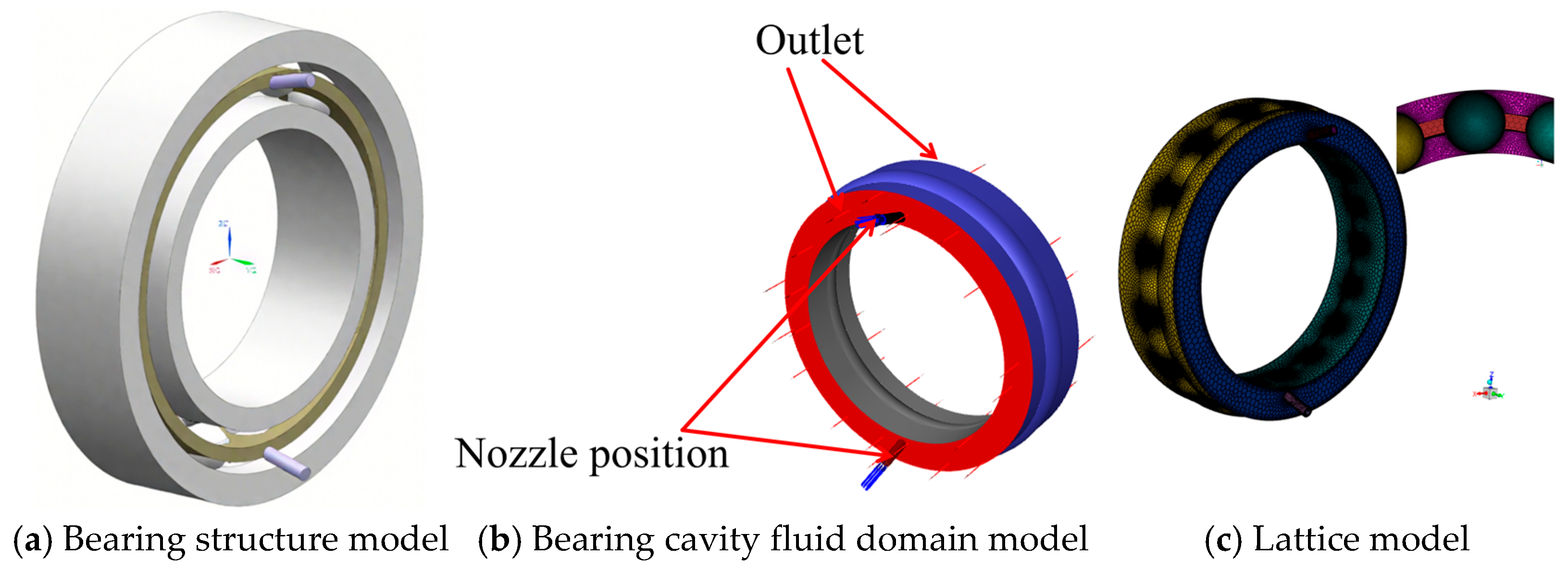
The 7008C angular contact ball bearing is taken as the object, and its structural parameters are shown in Table 1. The bearing structure, as well as the fluid domain model, is shown in Figure 1. The model includes the fluid domain in the bearing cavity and the nozzle. The bearing fluid domain model is meshed with polyhedral meshing using FLUENT Meshing 2022, a mesh type with strong automatic generation capability and a large number of neighboring cells, resulting in good convergence performance and high accuracy. The minimum orthogonal mass of this mesh model is 0.5, which is greater than 0.1 and has good convergence for flow field analysis.

Table 1.
Basic parameters of bearings.
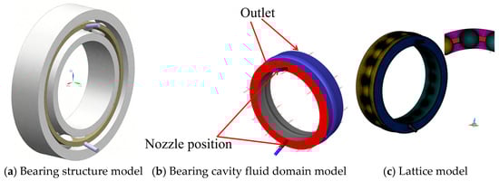
Figure 1.
Fluid domain and mesh model in the bearing cavity.
2.3. Boundary Conditions and Solution Setup
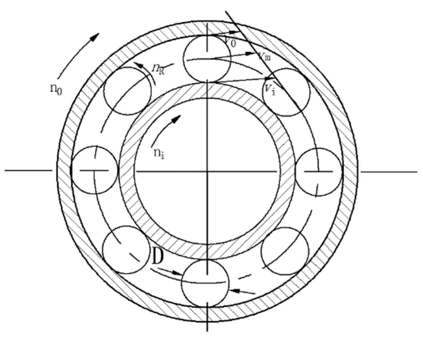
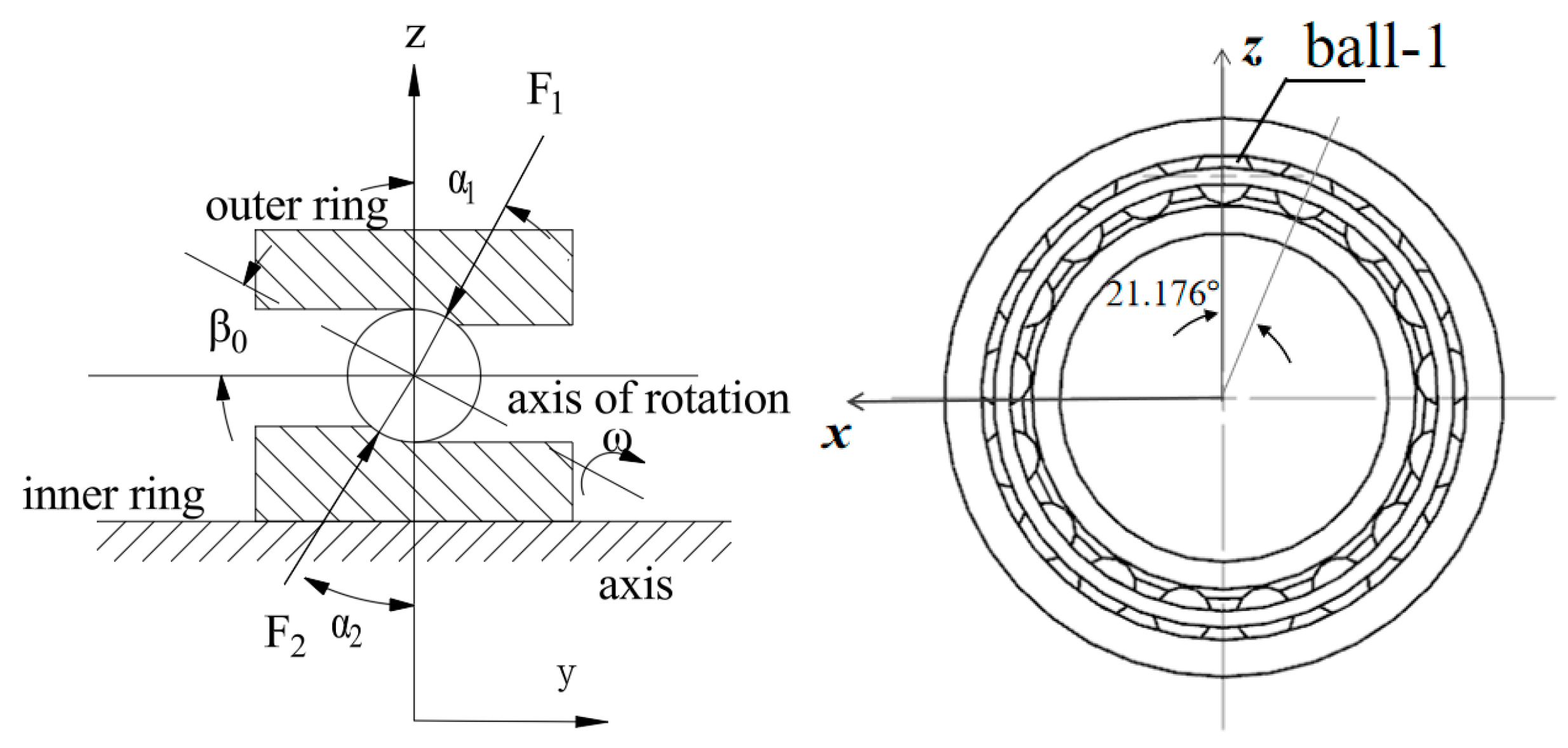
The inlet is a velocity inlet with an inlet oil phase temperature of 26 °C. The end face of the bearing chamber is the pressure outlet and the pressure is standard atmospheric pressure. During motion, the outer ring of the bearing remains stationary, so the outer wall surface of the bearing cavity is set as a stationary wall surface. The inner ring of the bearing rotates with the spindle, so the inner wall surface of the bearing cavity should be set as the rotating wall surface of the rotational speed of ni, the cage wall rotational speed is set to keep in line with the speed of the steel ball rotational nm, as shown in the bearing motion relationship shown in Figure 2.
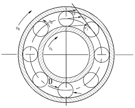
Figure 2.
Bearing motion relationship.
In the VOF and RNG k-ε Turbulence Model, standard wall functions are used to solve the setup. The material parameters of the lubricant with air and solids are shown in Table 2.
Table 2.
Material parameters.
When only the inner ring rotates and the outer ring is fixed, the rotational and spinning speeds of the steel ball are as follows [22]:
where dm is the diameter of the pitch circle, D is the diameter of the steel ball, ni is the speed of the inner ring, and α is the contact angle.
2.4. Model Validation
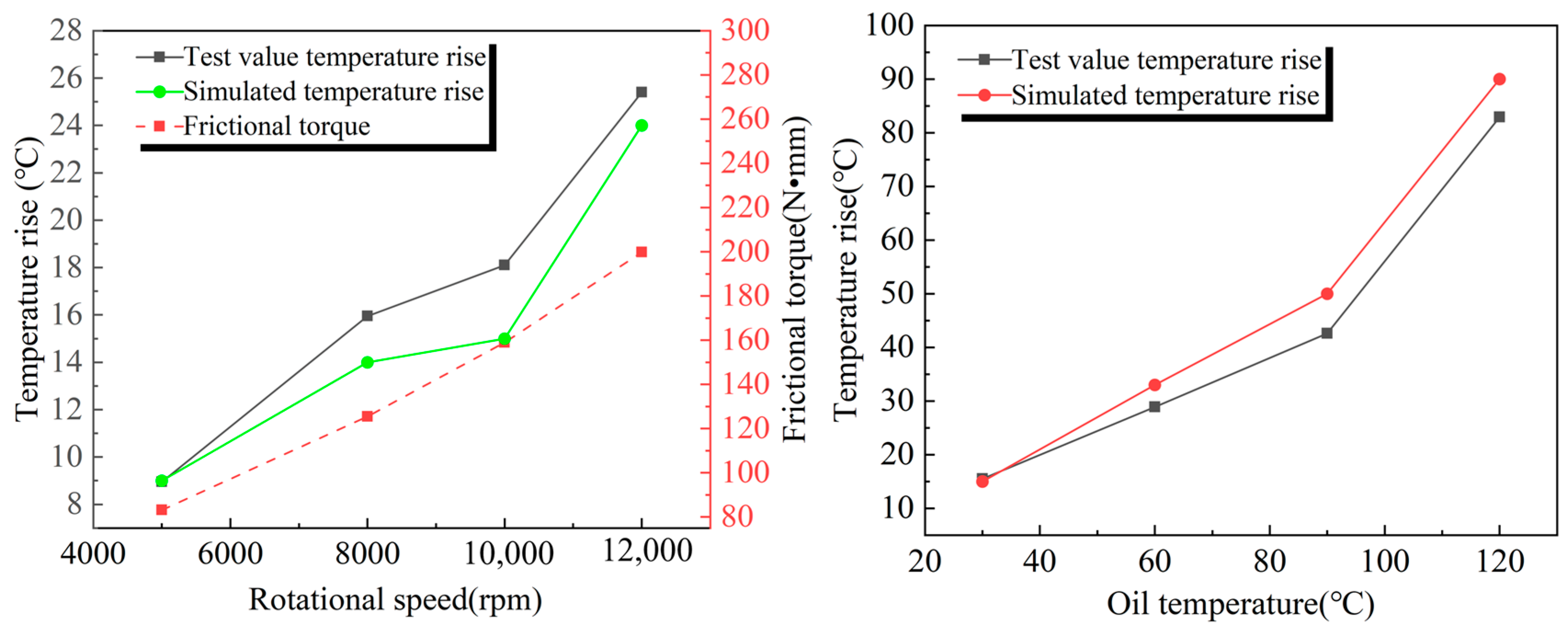
To verify the reliability of the model, a thermo–fluid–solid-coupled model was established for the same bearing cavity fluid domain while maintaining the same geometric parameters, boundary conditions, and basic settings. Its effectiveness was indirectly verified through an outer ring temperature rise test of the bearing.
As shown in Figure 3, the relative error between the finite element simulation results and the experimental data is small, and the change in the solid heat transfer coefficient has little effect on the temperature rise in the bearing outer ring, indicating that the flow–heat transfer characteristics of the fluid domain play a dominant role in the temperature rise process. This result verifies the accuracy of the mathematical model and further supports the validity of the air curtain effect.
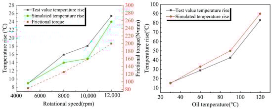
Figure 3.
Simulation values and experimental values of the outer ring of the bearing at different speeds and oil temperatures.
2.5. Rotation Axis and Geometric Centers
In practical working conditions, the steel balls not only perform a rotational motion, but also generate a spinning motion. This means that each steel ball not only rotates around the center axis of the bearing, but also rotates around a fixed axis of itself [23].
Foord, C. A. [24] provides a method for calculating this axis. As shown in Figure 4, the angle between the axis of rotation of the ball and the axis of rotation is β0, which is equal to half of the sum of the contact angle between the inner and outer rings of the ball bearing and the ball, i.e., β0 = (α1 + α2)/2. In this paper, we select the angular contact ball bearing 7008C with a contact angle of 15°. In order to simplify the analysis of the bearing structure, α1 = α2 = 15° is set so that we can obtain β0 = 15°.
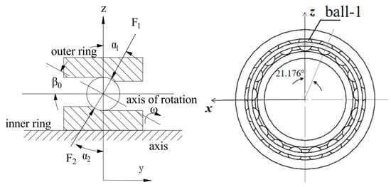
Figure 4.
Angle of rotation axis β0.
The origin of the spin of a steel ball is its own geometric center, and the axis of rotation can be represented by the unit direction vector. The 17 steel balls are numbered in counterclockwise order as shown in Figure 4, and the geometrical centers and axes of rotation of the steel balls are shown in Table 3.
Table 3.
Sphere geometry centers and axes of rotation.
3. Simulation Results Analysis
3.1. Lubricant Distribution Status
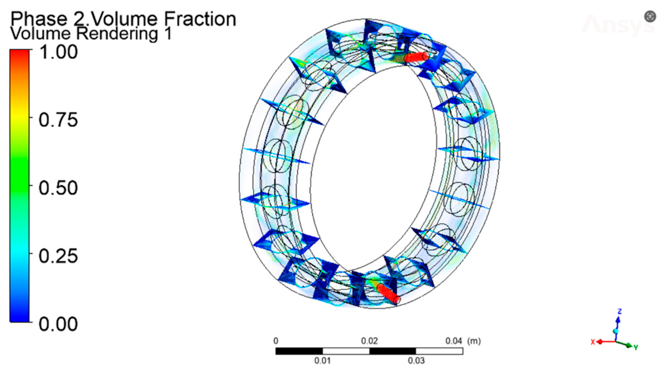
During high-speed rotation, the uniform distribution of lubricating oil within the bearing effectively reduces friction and wear, lowers operating temperature, and prevents direct contact between metal surfaces. The distribution of lubricating oil within the bearing cavity is shown in Figure 5a–c. The lubricating oil distribution on the steel ball surface is higher than that on the outer ring, while the lubricating oil distribution on the inner ring surface is relatively low.
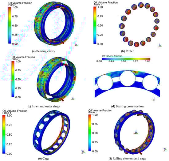
Figure 5.
Lubricant distribution status.
As shown in Figure 5d, after the lubricating oil enters the bearing cavity through the oil injection holes, under the influence of high rotational speed and centrifugal force, only a small portion remains on the inner surface of the bearing, while the majority of the lubricating oil is flung off and distributed on the inner surface of the outer ring. Additionally, as shown in Figure 5e, the retainer pocket holes are more prone to storing lubricating oil. Since there is lubricating oil in the pocket gaps, the steel balls can be effectively lubricated during rolling, thereby reducing the coefficient of friction and wear. This not only helps to form an oil film, reducing direct friction between the steel balls and the rolling bearing contact surfaces, but also effectively dissipates heat generated during operation, preventing local overheating.
As shown in Figure 5f, due to the centrifugal force generated by the high-speed rotation of the steel balls, the lubricating oil moves toward both sides of the steel balls under the influence of centrifugal force. The lubricating oil is pushed from the center of the steel ball toward the periphery. Meanwhile, the contact areas between the steel ball and the raceway are high-pressure zones, where the lubricating oil is compressed, limiting its flowability. The high pressure at these contact points also forces the lubricating oil out of the contact zones, reducing the amount of lubricating oil within them. This results in an overall distribution of lubricating oil toward the sides, while the contact zones have relatively less lubricating oil.
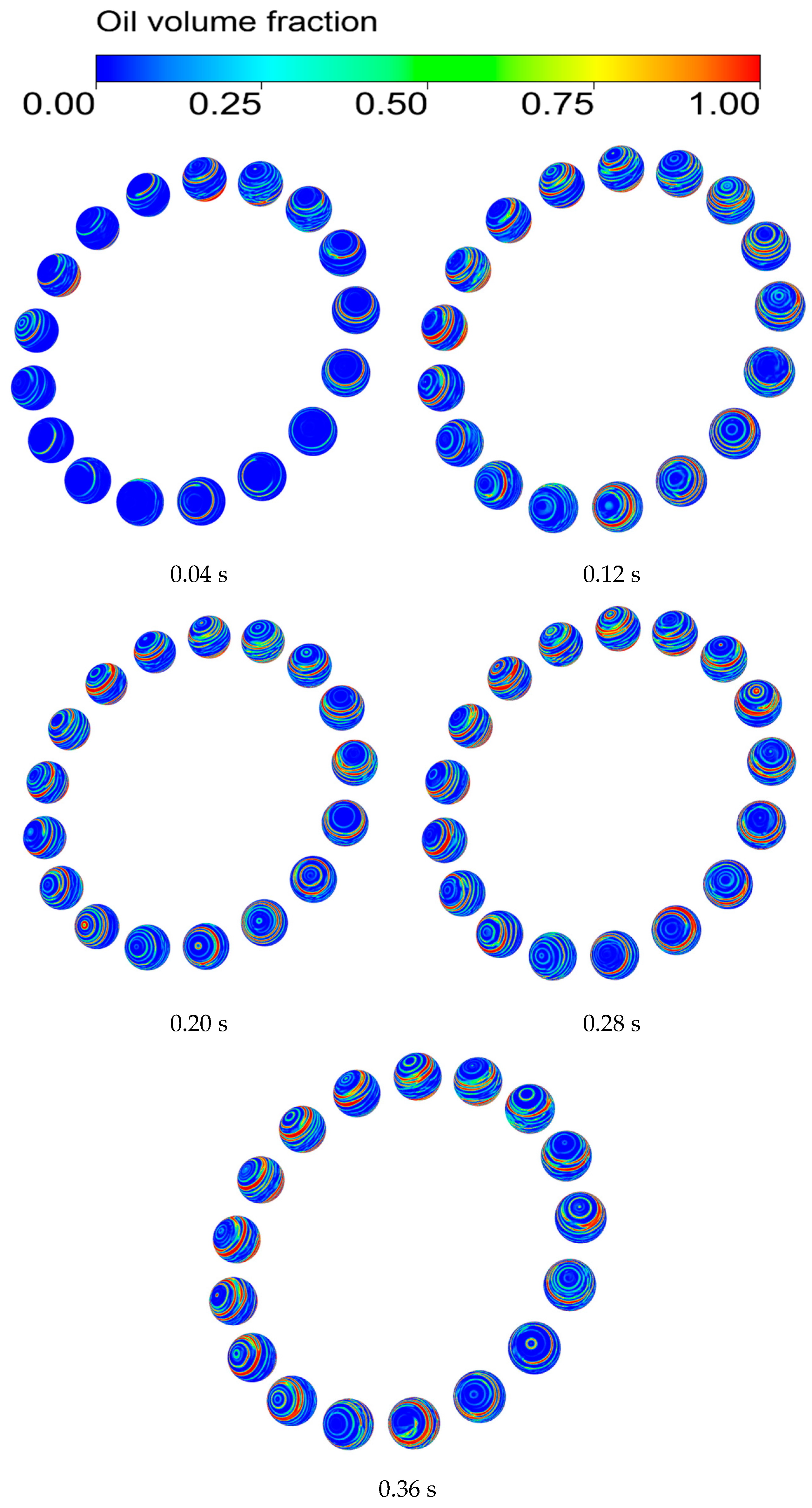
If the oil film on the surface of the rolling element is not sufficiently covered, dry friction will be triggered, leading to a rapid increase in bearing temperature, and consequently affecting bearing life. Therefore, to maintain the lubrication status of the bearing, it is important to study the lubricant distribution characteristics of the rolling element surface to maintain the normal operation of the bearing and to improve the lubrication effect of the bearing. Figure 6 shows the distribution of oil film formation on the surface of the rolling element and the gradual stabilization of the volume fraction of oil on the surface of the rolling element during the operation of the bearing.
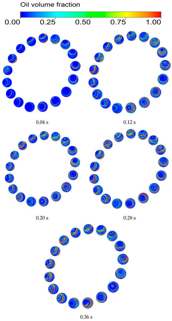
Figure 6.
The process of oil film formation on the surface of rolling bodies.
As shown in Figure 6, in the initial stage of the bearing startup (0.04 s), the lubricant is still in the initial diffusion and distribution process, the amount of oil on the surface of the rolling body is small and appears as a dot, and the lubricant is mostly concentrated at the steel ball near the nozzle.
At 0.12 s, the rolling body surface of the lubricating oil increased significantly, the surface of each ball appeared with a smaller block oil distribution, and due to the spinning motion of the steel ball, the lubricating oil gradually was shown along its own axis of rotation in the form of a circular line of oil.
At 0.20 s, the lubricant on the rolling element surface gradually flows toward both sides of the steel ball, resulting in the gradual increase in the surface of the steel ball block oil, a more obvious ring-shaped oil line, and the rolling body of the initial formation of the oil film.
During the period from 0.28 to 0.36 s, the lubricant on the surface of the rolling elements reaches a stable state, with a higher concentration near the contact area between the balls and the cage. In contrast, the distribution of the lubricant in the contact area between the inner and outer raceways becomes scarce.
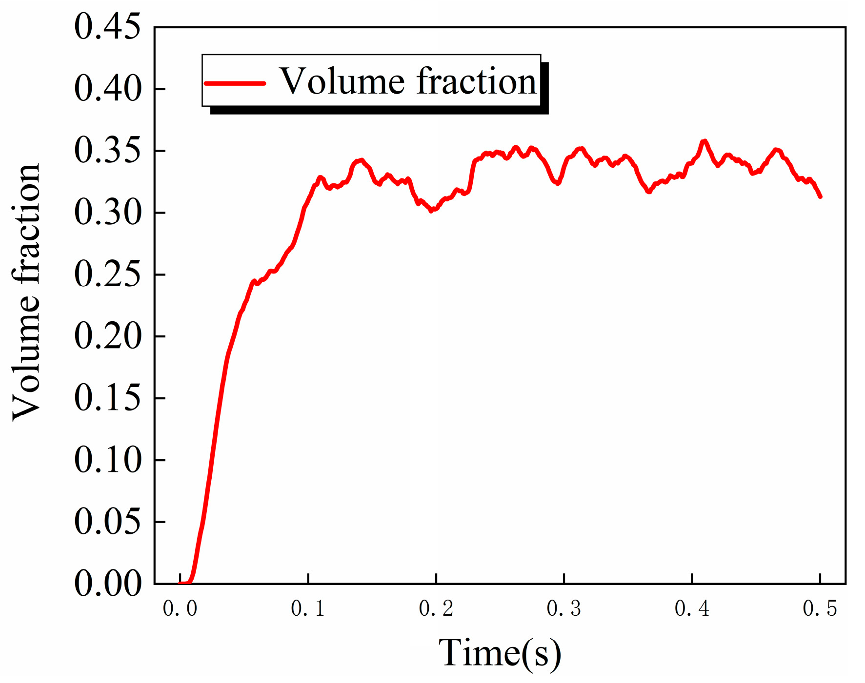
In order to further analyze the change rule of the lubricant on the surface of the rolling body, the volume fraction of the lubricant on the surface of the steel ball is weighted and averaged. As shown in Figure 7, the average oil volume fraction on the surface of the steel ball increases gradually with time change, reaches the maximum at about 0.1 s and begins to stabilize, and floats up and down between 0.3 and 0.35.
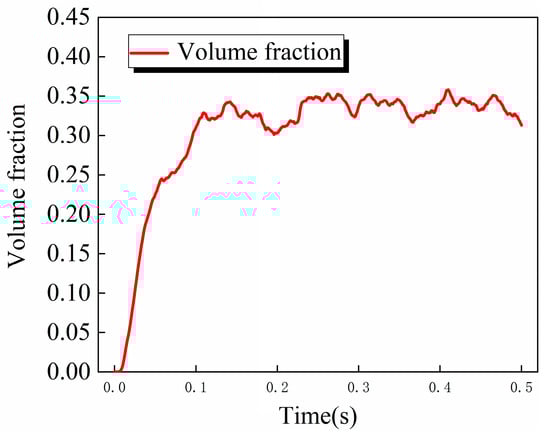
Figure 7.
Curve of average oil volume fraction on the surface of steel ball as a function of time.
3.2. Effect of Rotational Speed on the Volume Fraction of Oil on the Surface of Steel Balls
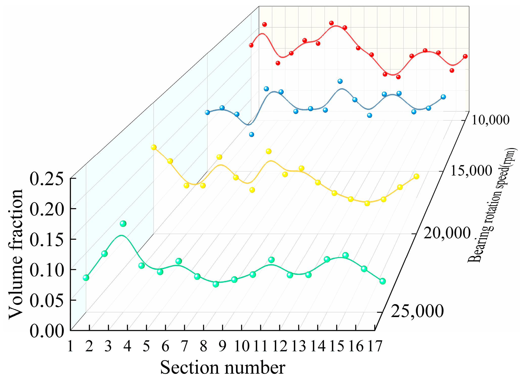
Starting at the upper nozzle, 17 locations were uniformly intercepted at 21.17° intervals along the counterclockwise direction to calculate the oil volume fraction, as shown in Figure 8. The oil volume fraction in each cross-section was weighted and averaged. The average value is obtained by considering the relative area weights of each region in the overall cross-section to more accurately represent the distribution of the oil fluid over the entire cross-section. As can be seen from Figure 9, at the same injection volume, the variation in the oil volume fraction in each cross-section at different rotational speeds is not the same, and the oil volume fraction gradually decreases as the rotational speed increases. At lower rotational speeds, the volume fraction of oil in each cross-section is higher; at higher rotational speeds, the volume fraction of oil in each cross-section is lower.

Figure 8.
Axial cross-section volume fraction.
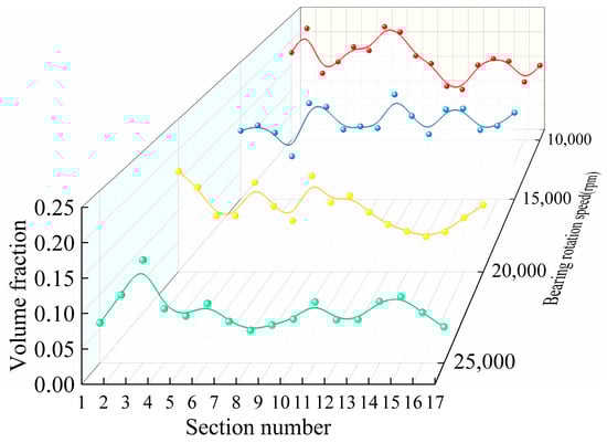
Figure 9.
Volume fraction of oil in each section at different rotational speeds.
3.3. Air Curtain Effect in the Bearing Cavity
3.3.1. Influence of Oil Jet Velocity on Air Curtain Effect in Bearing Cavity
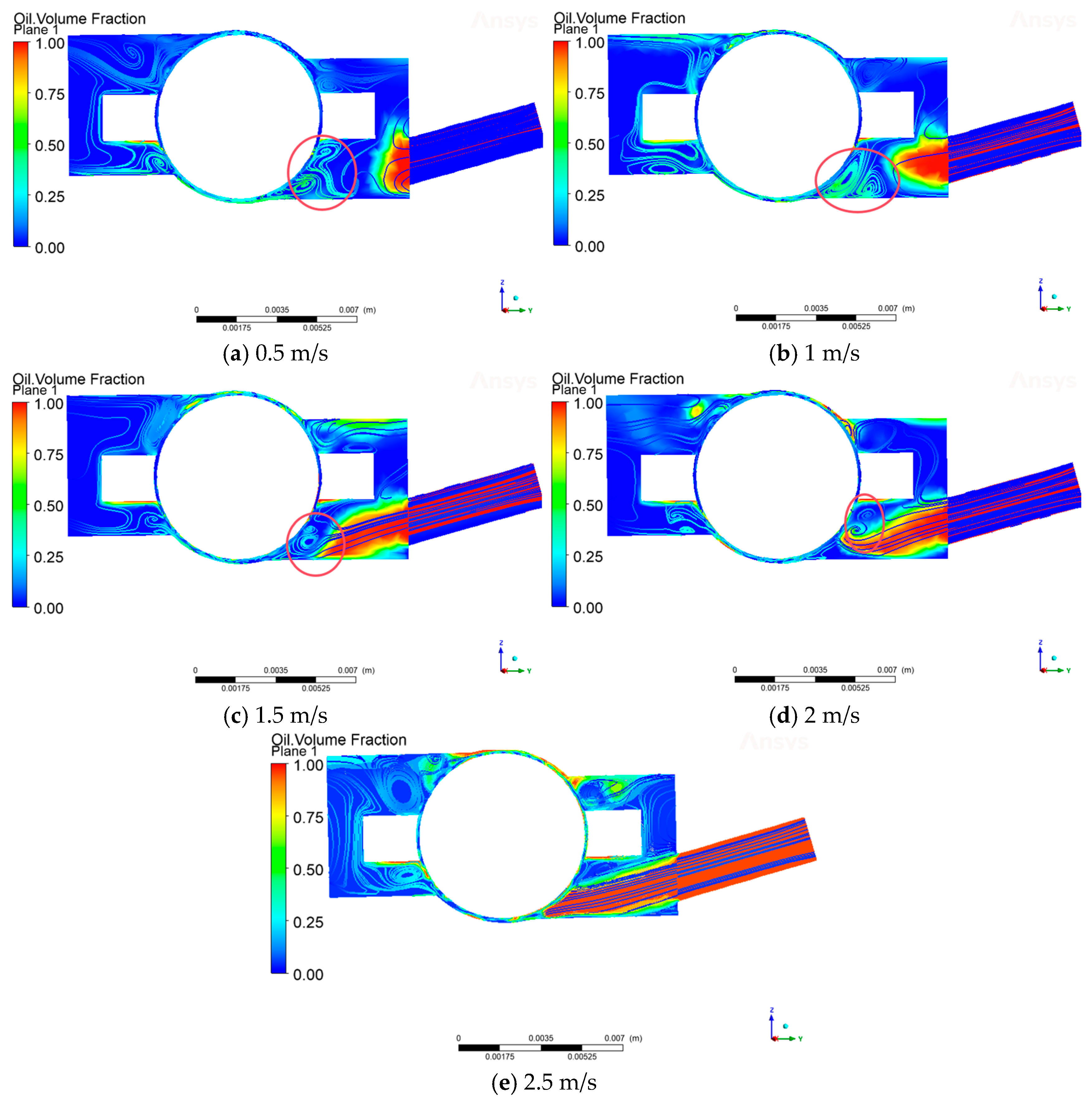
At low oil supply flow rates, air curtains form around the steel balls due to the high rotational speeds of the bearings. The appearance of the air curtain leads to a significant reduction in the spraying efficiency of the lubricant inside the bearing, which results in a weakening of the lubrication effect. Therefore, optimizing the oil injection speed to overcome the influence of the air curtain effect is a key research direction to improve the lubrication performance of bearings.
In this paper, by setting the rotational speed of 10,000 rpm and the lubricant flow rate of 0.5 m/s, 1 m/s, 1.5 m/s, 2 m/s, 2.5 m/s, the influence of the oil injection speed on the formation of the air curtain and its lubrication effect can be explored. As can be seen from Figure 10, when the oil spraying speed at 0.5m/s, due to the lower speed, under the influence of the air curtain effect, the rolling body and the inner ring of the contact area form a vortex. At this time, the lubricant flow trajectory changes, preventing the lubricant from reaching the lubrication contact point; with the increase in the oil spraying speed, the nozzle at the lubricant dispersion rate slowed down significantly, and the lubricant was sprayed in a straight line with a certain amount of kinetic energy. When the injection speed reaches 2.5 m/s, the inertia of the lubricant is greater, and the inertia force can make the lubricant maintain its original straight line trajectory; at this time, the kinetic energy of the lubricant is increased to better fight against the resistance of the air curtain, thus reducing the air curtain on the interference of the fluid path, overcoming the effect of the air curtain to reach the lubrication point.

Figure 10.
Air curtain effect in the bearing cavity at different oil injection volumes.
3.3.2. Influence of Rotational Speed on the Air Curtain Effect in the Bearing Cavity
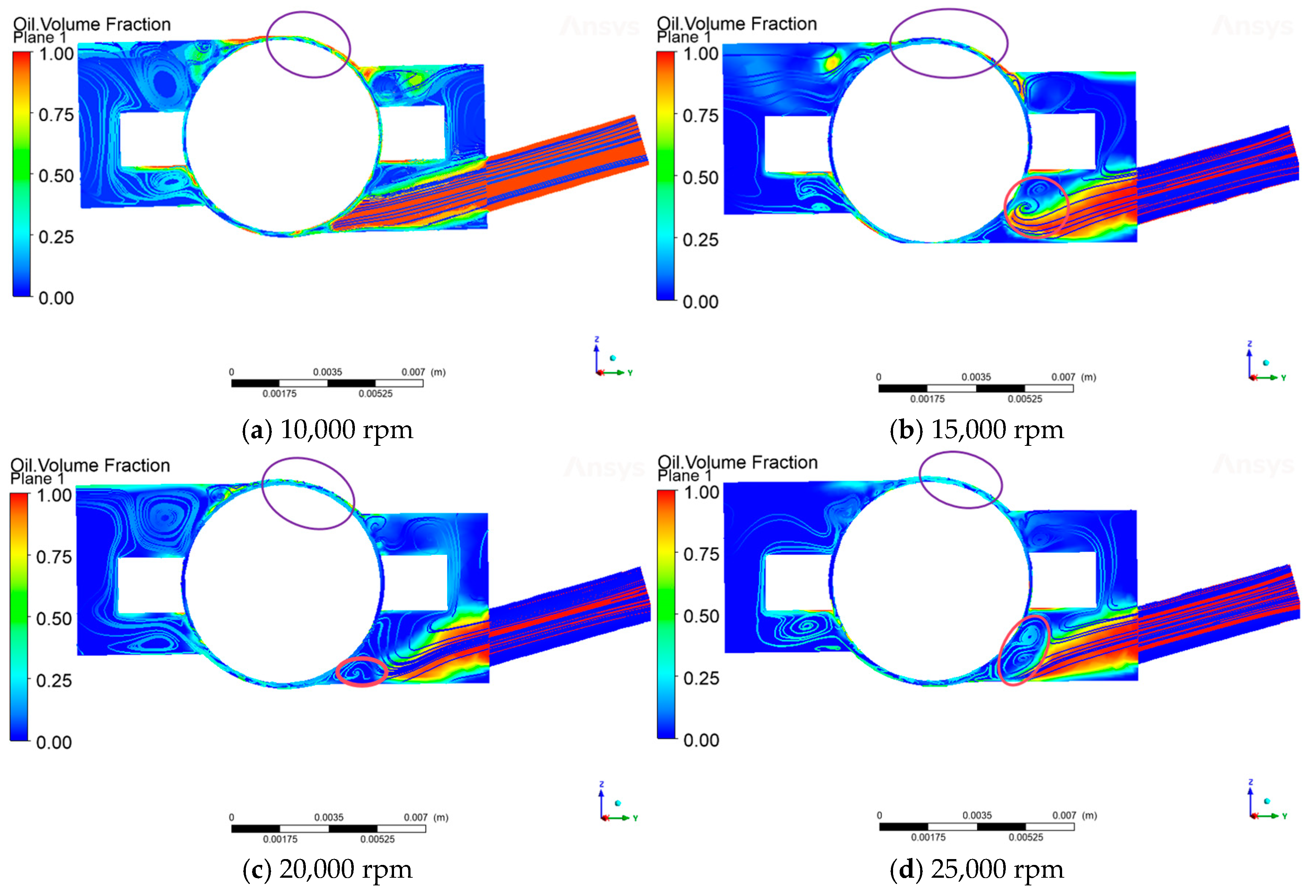
As can be seen from Figure 11, when the bearing speed is 10,000 rpm and the oil injection speed is 2.5 m/s, the vortex between the rolling body of the bearing and the outer surface of the inner ring is not obvious, and the lubricant can reach the lubrication point smoothly. When the injection speed remains unchanged, as the speed increases, the shear force of the air curtain is directly proportional to the bearing speed, and the air curtain strength increases, resulting in the end of the lubricant being pulled up by the airflow, in the steel ball, and the inner ring of the contact area to form more and more obvious vortexes (red circle in the diagram). The lubricant carries the kinetic energy, which is difficult to overcome, by speed to enhance the significant enhancement of the shear effect of the curtain. The kinetic energy carried by the lubricant is difficult to overcome the air curtain shear effect, which is significantly enhanced by the speed increase, resulting in the lubrication point of the transportation process being blocked. More critically, as the speed increases, the oil-phase volume fraction in the contact area between the steel ball and the outer raceway shows an obvious decreasing trend (purple circle in the diagram), which directly affects the lubrication performance of the rolling body contact surface. According to (Figure 9), with the increase in bearing speed, the oil volume fraction of each monitoring cross-section shows a significant decreasing trend, and this phenomenon indirectly verifies the enhancement of the air curtain effect in high-speed working conditions.

Figure 11.
Air curtain effect in the bearing cavity at different speeds.
3.3.3. Establishment of Air Curtain Blocking Factor K
In order to quantitatively express the influence mechanism of oil injection speed and rotational speed on the air curtain effect of the angular contact ball bearing 7008C, this study defines the blocking coefficient K (see Equation (16)) as an evaluation index of the intensity of the air curtain effect, whose physical significance indicates the effective ability of the lubricant to penetrate the air curtain barrier to reach the lubrication point. Based on this parameter, the interaction between the oil injection volume and the bearing speed is investigated through the simulation results, which in turn reveals the influence of both the strength of the air curtain effect and the lubrication efficiency.
where k is taken as 0.095, and m is 2, and where voil is the injection speed (m/s) and vair is the air curtain speed (m/s).
When vilo >> vair, the speed of oil injection is far higher than the blocking effect of the air curtain, K → 0, which means that the oil injection can easily pass through the air curtain.
When voil << vair, the speed of the air curtain is so great that the oil injection cannot pass through the air curtain, K → 1, which means that the air curtain completely blocks the oil injection.
The air curtain speed vair can be estimated from the rotational speed of the bearings and derived as follows:
where D is the inner diameter of the inner ring of the bearing/m, and N is the speed of the bearing/rpm.
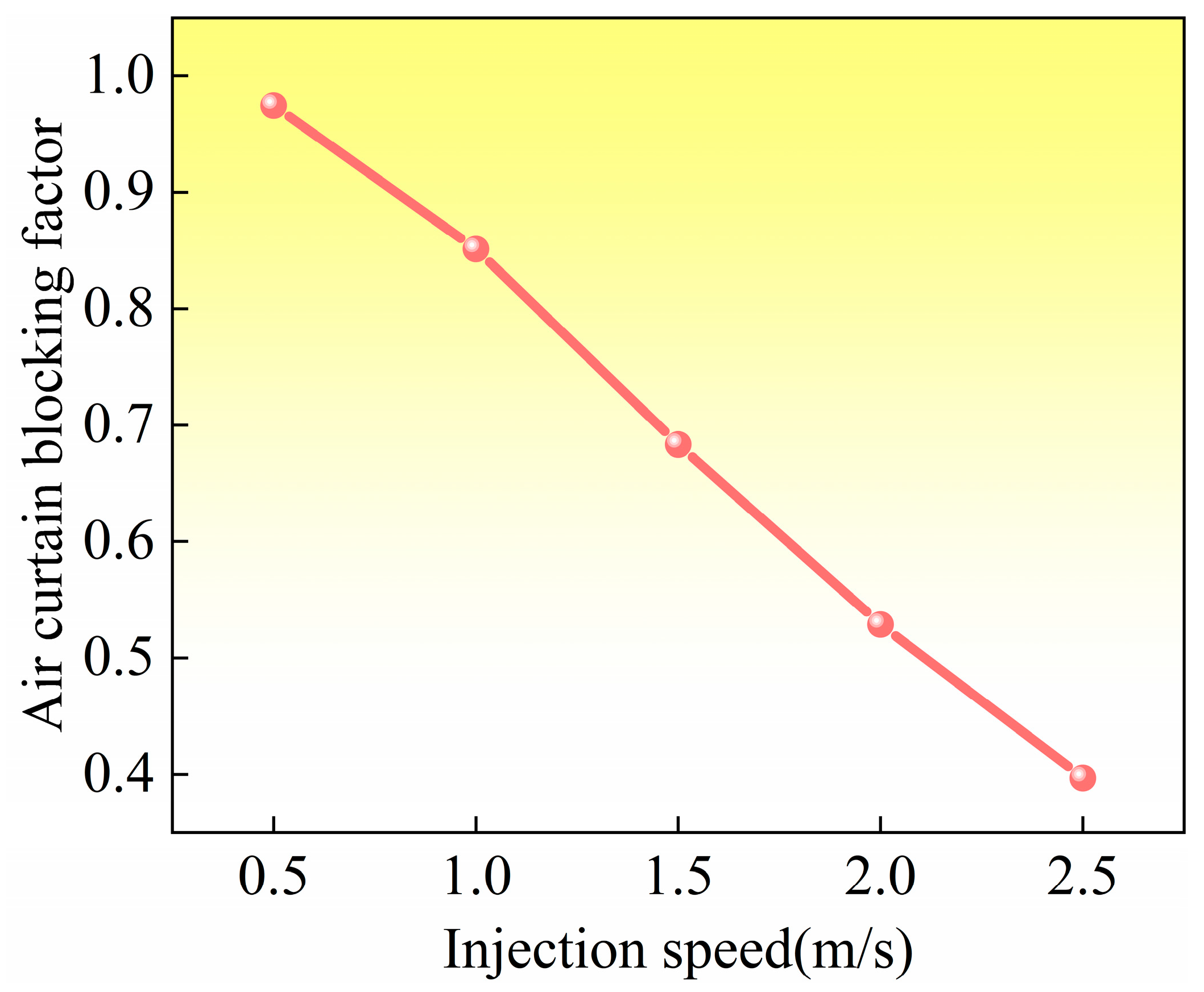
Figure 12 shows the influence of injection speed on the air curtain blocking coefficient (K) at 10,000 rpm; as the injection speed increases, the value of K gradually decreases. The critical state occurs when the injection speed is 2.0 m/s, and the K value is about 0.5. At this point, the lubricant is close to reaching, but not able to reach, the lubrication point, which clearly confirms that the air curtain effect is still the main limiting factor for lubrication transfer. Continuing to increase the injection rate to 2.5 m/s, the K-value was reduced to 0.39, and a significant reduction in the air curtain effect was observed. This visually demonstrates the effectiveness of suppressing the air curtain effect by increasing the injection rate.
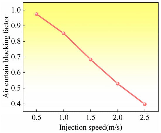
Figure 12.
Variation in air curtain blocking coefficient with injection rate.
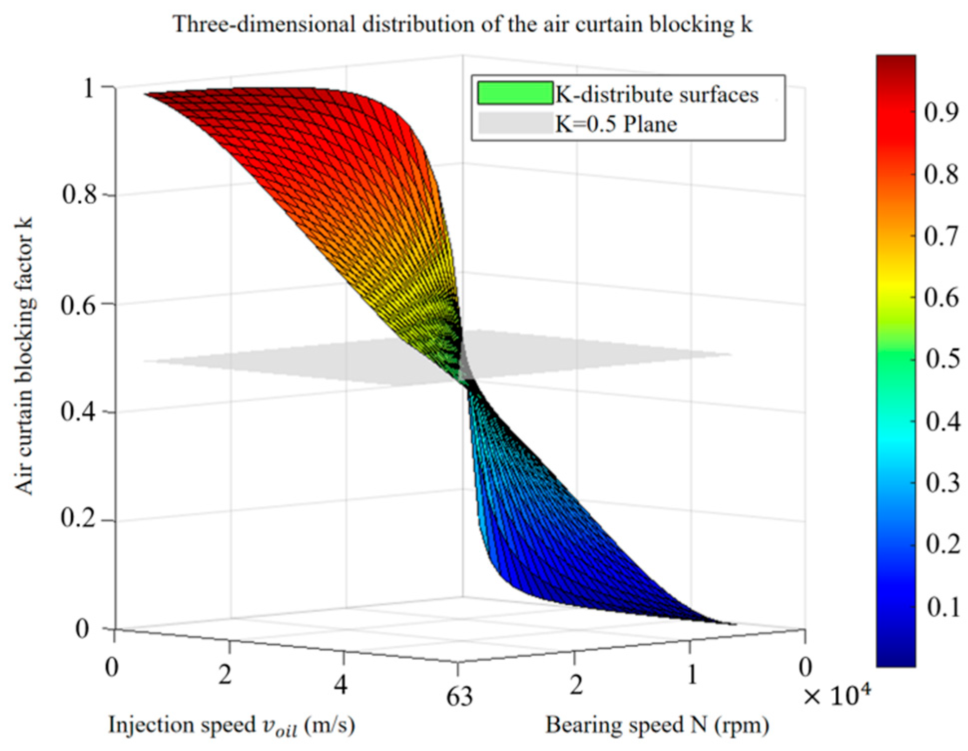
The above results directly verify the core regulation mechanism that regulating the air curtain strength by optimizing the injection rate is the key to achieving effective lubricant delivery. The significant improvement in the lubrication effect when the K value is reduced to 0.39 in Figure 12 verifies the theoretical critical value (K < 0.5); the lubricant is able to effectively penetrate the air curtain to reach the lubrication point. Figure 13 further reveals the systematic influence of injection speed and rotational speed on the air curtain effect; increasing the injection speed can significantly inhibit the air curtain effect (especially at low rotational speeds), and decreasing the rotational speed can also weaken its effect. Therefore, especially under high-speed conditions, the injection speed must be reasonably adjusted according to the law (i.e., regulating the injection speed or rotational speed) revealed in Figure 12 and Figure 13 in order to precisely control the air curtain effect and ensure the reliable transmission of lubricating oil.
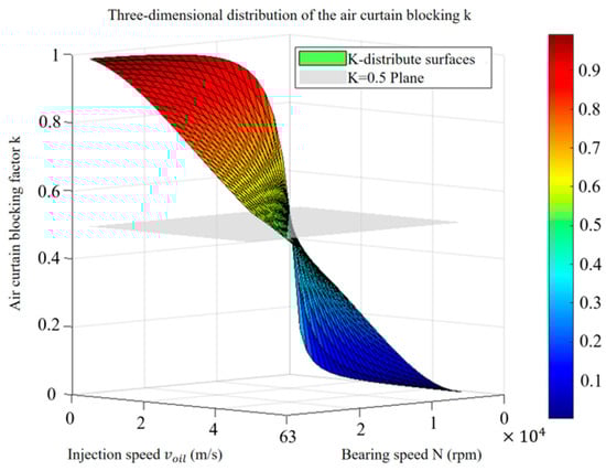
Figure 13.
Changing law of blocking coefficient K.
4. Conclusions
- The lubricant is affected by centrifugal force and contact pressure, etc., in the high-speed rotating bearings, and it spreads from the vicinity of the nozzle to both sides of the steel ball, gradually forming a stable oil film. The contact area results in less oil due to high pressure distribution.
- The intensity of the air curtain effect increases with the increase in rotational speed, which produces shear and other disturbances in the lubricant path. Under the influence of the air curtain effect, the end of the lubricant will produce the phenomenon of “warping”, resulting in a decrease in the lubrication effect.
- Increasing the injection speed can effectively weaken the air curtain effect, and the air curtain blocking coefficient K is established; when K is reduced to below 0.4, the lubricant can penetrate the air curtain smoothly. Under different rotational speeds, reasonable adjustment of the oil injection speed can improve the lubrication effect under different working conditions.
Author Contributions
Methodology, Y.D.; Validation, Z.Y., H.Z., W.Y., J.S. and W.Z.; Writing–original draft, B.Y.; Writing–review & editing, B.Y. All authors have read and agreed to the published version of the manuscript.
Funding
National Natural Science Foundation of China Young Scientist Program (52205096); Open Fund Project of the National Key Laboratory of Interface Science and Technology for Advanced Equipment, Tsinghua University (SKLTKF24B09).
Data Availability Statement
The original contributions presented in this study are included in the article. Further inquiries can be directed to the corresponding author(s).
Conflicts of Interest
Hai Zhang was employed by Suzhou Bearing Factory Co., Ltd., and Janyong Sun was employed by Luoyang Bearing Research Institute Co., Ltd. The remaining authors declare that the research was conducted in the absence of any commercial or financial relationships that could be construed as a potential conflict of interest.
References
- Wen, B.; Li, Y.; Li, Y.; Wang, M.; Zhai, J. Influence and Optimization of Nozzle Position on Lubricant Distribution in an Angular Contact Ball Bearing Cavity. Lubricants 2024, 12, 419. [Google Scholar] [CrossRef]
- Wu, M.; Wu, W.; Yuan, S.; Hu, J. Study of multiple-point oil-jet lubrication of high-speed ball bearings. Power Transm. Eng. 2014, 6, 44–46. [Google Scholar]
- Hu, J.; Wu, W.; Wu, M.; Yuan, S. Numerical investigation of the air–oil two-phase flow inside an oil-jet lubricated ball bearing. Int. J. Heat Mass Transf. 2014, 68, 85–93. [Google Scholar] [CrossRef]
- Zhang, R.; Wei, C.; Wu, W.; Yuan, S. CFD investigation on the influence of jet velocity of oil-jet lubricated ball bearing on the characteristics of lubrication flow field. In Proceedings of the 2015 International Conference on Fluid Power and Mechatronics (FPM), Harbin, China, 5–7 August 2015; IEEE: Piscataway, NJ, USA, 2015; pp. 1324–1328. [Google Scholar]
- Lu, P.; Ye, Q.; Fang, L.; Yang, P.; Yang, Q. Research on the air–oil two-phase flow regime in an aeroengine bearing chamber based on Hilbert–Huang transform. Proc. Inst. Mech. Eng. Part G J. Aerosp. Eng. 2022, 236, 24–32. [Google Scholar] [CrossRef]
- Bao, H.; Hou, X.; Lu, F. Analysis of oil-air two-phase flow characteristics inside a ball bearing with under-race lubrication. Processes 2020, 8, 1223. [Google Scholar] [CrossRef]
- Gao, W.; Li, C.; Li, Y.; Liu, Z.; Lyu, Y. Oil–air two-phase flow distribution characteristics inside cylindrical roller bearing with under-race lubrication. Lubricants 2024, 12, 133. [Google Scholar] [CrossRef]
- Lu, F.; Wang, T.; Zhao, Z. Thermal characteristics for bearing combined EHL theory with CFD method. J. Aerosp. Power 2020, 35, 1204–1210. [Google Scholar]
- Liu, J.; Ni, H.; Zhou, R.; Li, X.; Xing, Q.; Pan, G. A simulation analysis of ball bearing lubrication characteristics considering the cage clearance. J. Tribol. 2023, 145, 044301. [Google Scholar] [CrossRef]
- Zhang, J.J.; Lu, L.M.; Zheng, Z.Y.; Gan, L.; Lv, Z.Y. Visual comparative analysis for the oil-air two-phase flow of an oil-jet lubricated roller-sliding bearing. J. Appl. Fluid Mech. 2022, 16, 179–191. [Google Scholar]
- Bei, Y.; Lei, D.; Ke, Y. Effects of oil-air lubrication methods on the internal fluid flow and heat dissipation of high-speed ball bearings. Mechnical Syst. Signal Process. 2021, 151, 107409. [Google Scholar]
- Jiang, L.; Lyu, Y.; Gao, W.; Zhu, P.; Liu, Z. Numerical investigation of the oil–air distribution inside ball bearings with under-race lubrication. Proc. Inst. Mech. Eng. Part J J. Eng. Tribol. 2022, 236, 499–513. [Google Scholar] [CrossRef]
- Gao, S.; Hou, X.; Ma, C.; Yang, Y.; Li, Z.; Yin, R.; Zhu, R. Transient simulation analysis of needle roller bearing in oil jet lubrication and planetary gearbox lubrication conditions based on computational fluid dynamics. Lubricants 2024, 12, 39. [Google Scholar] [CrossRef]
- Ge, L.; Yan, K.; Wang, C.; Zhu, Y.; Hong, J. A novel method for bearing lubrication enhancement via the inner ring groove structure. J. Phys. Conf. Ser. 2021, 1820, 012092. [Google Scholar] [CrossRef]
- Liu, J.; Ni, H.; Xu, Z.; Pan, G. A simulation analysis for lubricating characteristics of an oil-jet lubricated ball bearing. Simul. Model. Pract. Theory 2021, 113, 102371. [Google Scholar] [CrossRef]
- Zhu, W.; Zhu, R.; Tang, X.; Lu, F.; Bai, X.; Wu, X.; Li, F. CFD-based analysis of oil and gas two-phase flow characteristics in double-row tapered roller bearings with different rib structures. Appl. Sci. 2022, 12, 1156. [Google Scholar] [CrossRef]
- Gong, P.; Liu, Z.; Yu, Q.; Chen, F. Research on internal two-phase flow in the local micro-clearance design of a high-speed ball bearing with under-race lubrication. Lubr. Sci. 2024, 36, 216–230. [Google Scholar] [CrossRef]
- Ramdin, M.; Henkes, R. Computational fluid dynamics modeling of Benjamin and Taylor bubbles in two-phase flow in pipes. J. Fluids Eng. 2012, 134, 041303. [Google Scholar] [CrossRef]
- Banerjee, R.; Isaac, K.M.; Oliver, L.; Breig, W. Features of automotive gas tank filler pipe two-phase flow: Experiments and computational fluid dynamics simulations. J. Eng. Gas Turbines Power 2002, 124, 412–420. [Google Scholar] [CrossRef]
- Xiao, J.; Zhu, E.; Wang, G. Numerical simulation of emergency shutdown process of ring gate in hydraulic turbine runaway. J. Fluids Eng. 2012, 134, 124501. [Google Scholar] [CrossRef]
- Lyu, Y.; Li, Y.; Li, C.; Jiang, L.; Liu, Z. Oil-air distribution prediction inside ball bearing with under-race lubrication based on numerical simulation. Appl. Sci. 2024, 14, 3770. [Google Scholar] [CrossRef]
- Shan, W.; Chen, Y.; Huang, J.; Wang, X.; Han, Z.; Wu, K. A multiphase flow study for lubrication characteristics on the internal flow pattern of ball bearing. Results Eng. 2023, 20, 101429. [Google Scholar] [CrossRef]
- Adeniyi, A.A.; Morvan, H.P.; Simmons, K.A. A multiphase computational study of oil-air flow within the bearing sector of aeroengines. In Proceedings of the ASME Turbo Expo 2015: Turbine Technical Conference and Exposition, Montreal, QC, Canada, 15–19 June 2015; American Society of Mechanical Engineers: New York, NY, USA, 2015; Volume 56734, p. V05CT15A024. [Google Scholar]
- Foord, C.A. High-speed ball bearing analysis. Proceedings of the Institution of Mechanical Engineers. Part G J. Aerosp. Eng. 2006, 220, 537–544. [Google Scholar]

Disclaimer/Publisher’s Note: The statements, opinions and data contained in all publications are solely those of the individual author(s) and contributor(s) and not of MDPI and/or the editor(s). MDPI and/or the editor(s) disclaim responsibility for any injury to people or property resulting from any ideas, methods, instructions or products referred to in the content. |
© 2025 by the authors. Licensee MDPI, Basel, Switzerland. This article is an open access article distributed under the terms and conditions of the Creative Commons Attribution (CC BY) license (https://creativecommons.org/licenses/by/4.0/).