Twin-Disc Wear Assessment of Solid Stick Flange Lubricants †


Abstract
1. Introduction
- The ability to reduce and control the coefficient of friction (CoF) when the solid stick product is applied to the wheel flange; the friction level could be used to give an indication of relative material wear rates.
- The durability of the applied film once the solid stick product is removed; this provides an indication of how long the applied film will last when transferred from the wheel flange to the rail gauge side face and, therefore, how effective the film will be at protecting wheelsets not equipped with the product.
2. Experimental Details
2.1. Products
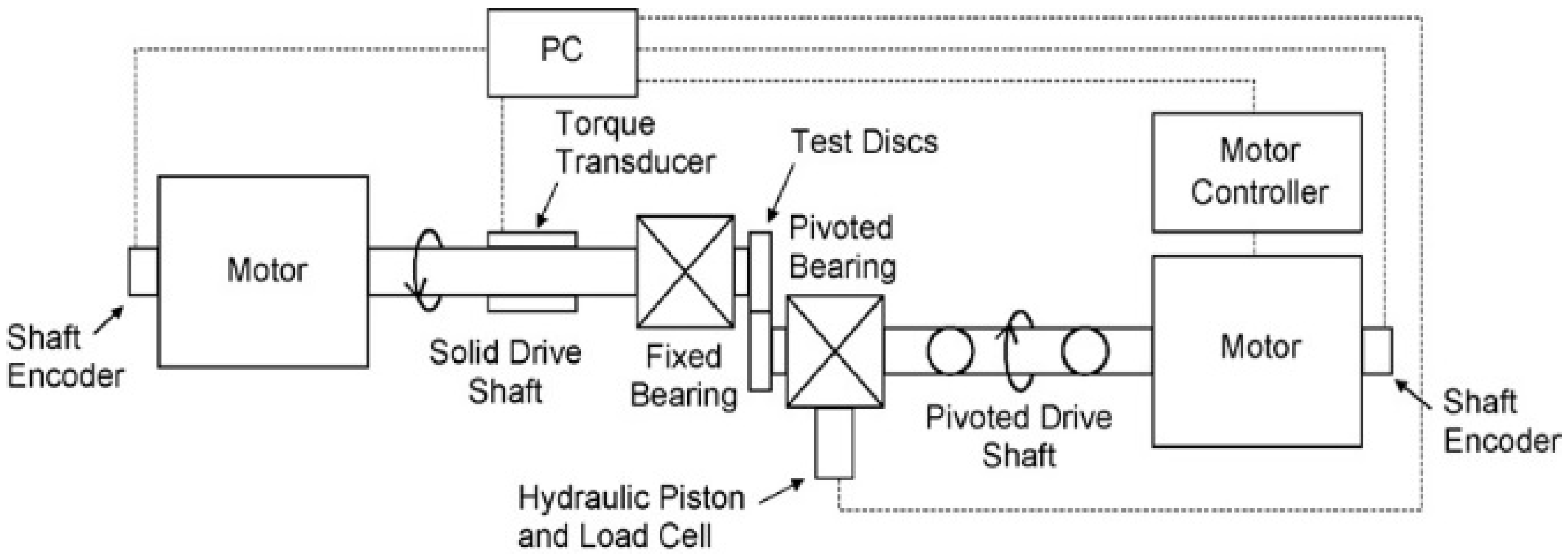
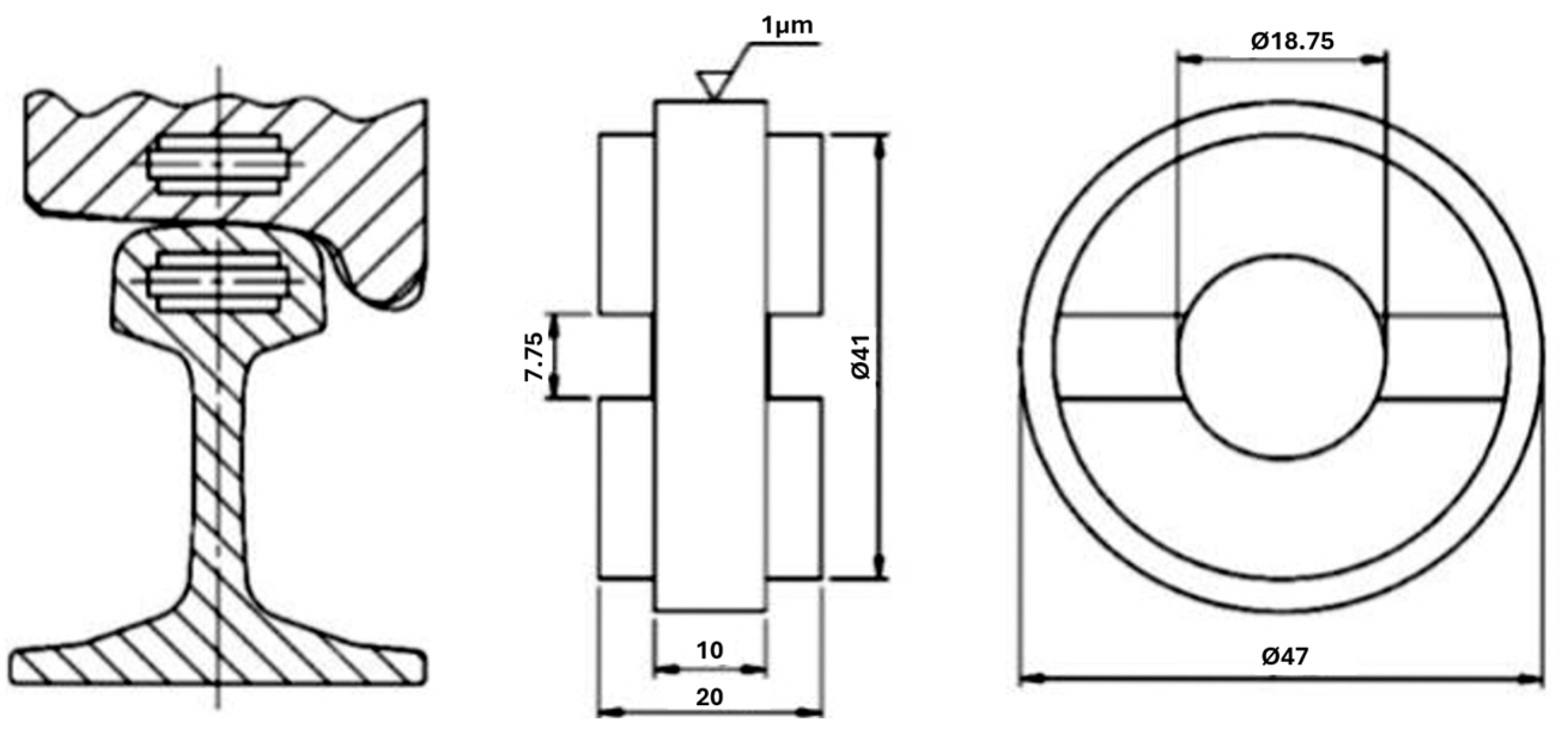
2.2. Test Apparatus
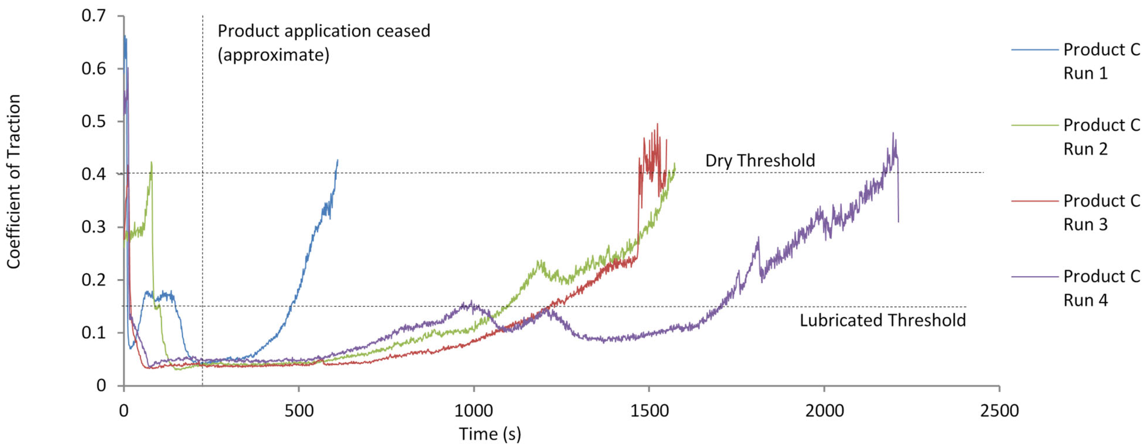
2.3. EN 15427-2-1:2022 Retentivity Test Methodology
- Discs in contact throughout test, 900 MPa maximum pressure, 10% creep at 400 RPM. Discs cooled using air flow.
- Product applied for 200 s and then released.
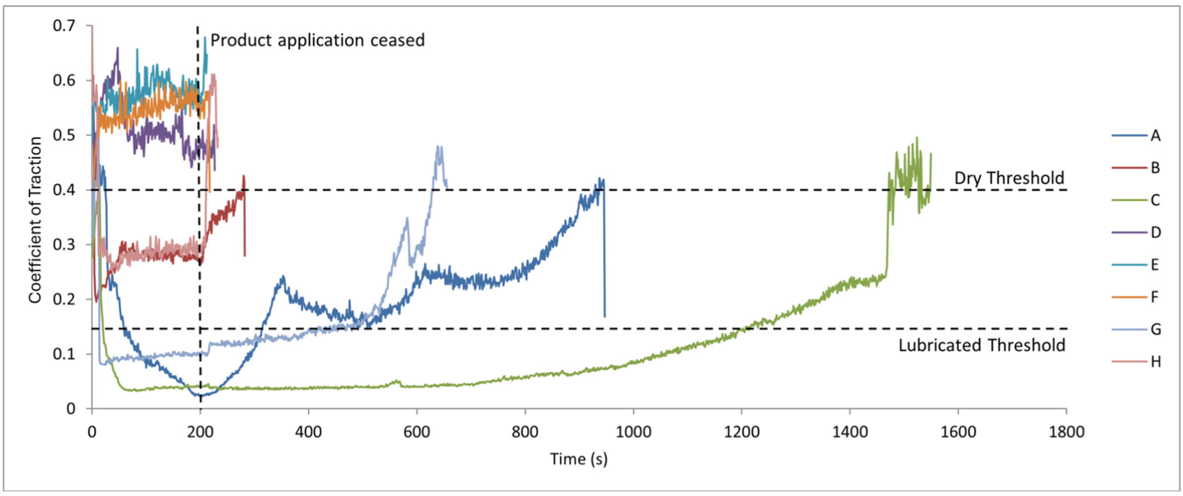
- Test ends when friction level rises above 0.4.
- Coefficient of traction and creepage are monitored throughout the test. Mass loss of both product and test discs is also recorded.
- EN 15427-2-1:2022 [22] specifies that testing should be repeated at least three times. Each trial has at least three repeats; however, some results had to be discounted as faults were uncovered (i.e., a significant misalignment between product and disc).
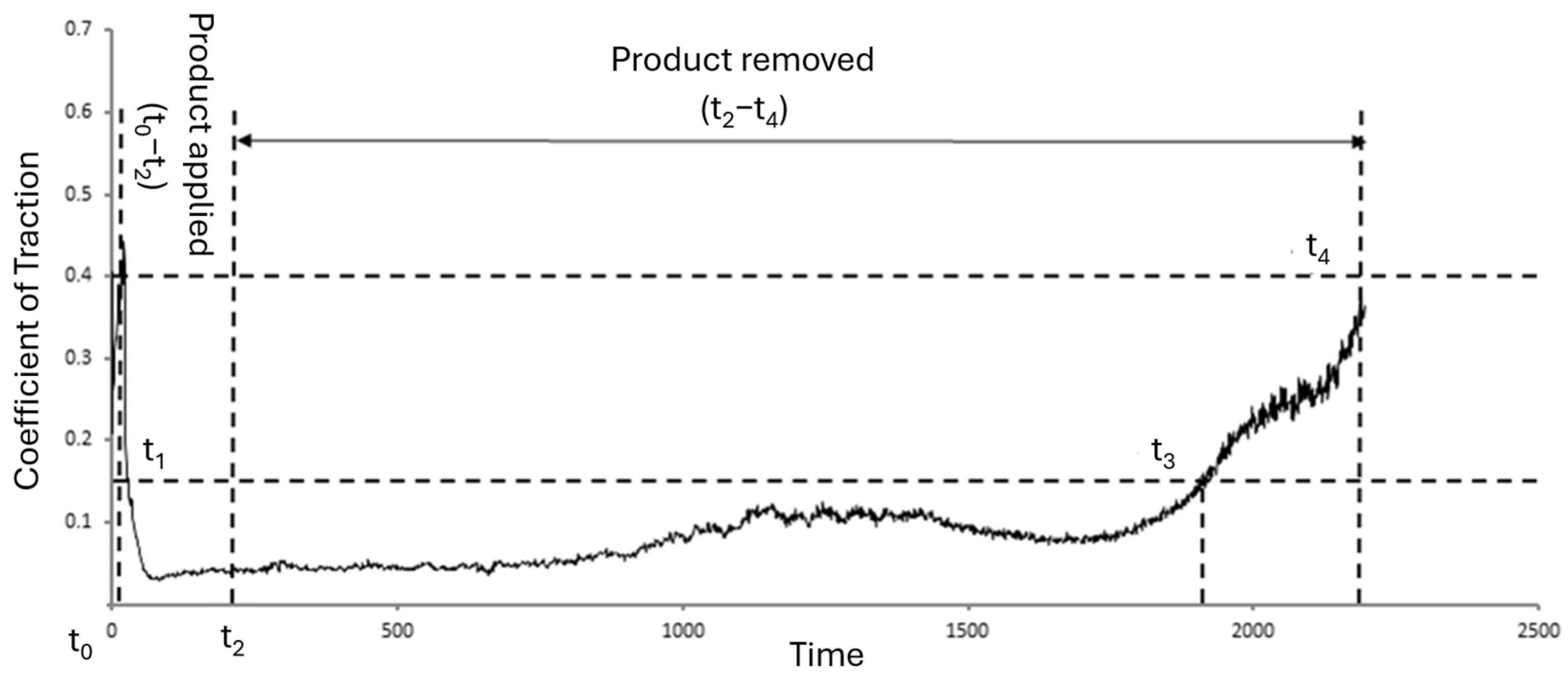
- The assessment criteria specified in EN 15427-2-1:2022 [22] are as follows:
- Product response (t1−t0)—time taken (s) for the product to lubricate the interface upon product application.
- Coefficient of traction during product application (mean).
- Retentivity (t4−t2)—time taken (s) for the coefficient of traction to return to 0.4 after product application has ceased.
- Product consumption—the amount of product consumed during the test (mm3).
- Typical performance data is shown in Figure 4.
- Low product response time (s);
- Low coefficient of traction;
- High retentivity (s);
- Low product consumption—by volume (mm3).
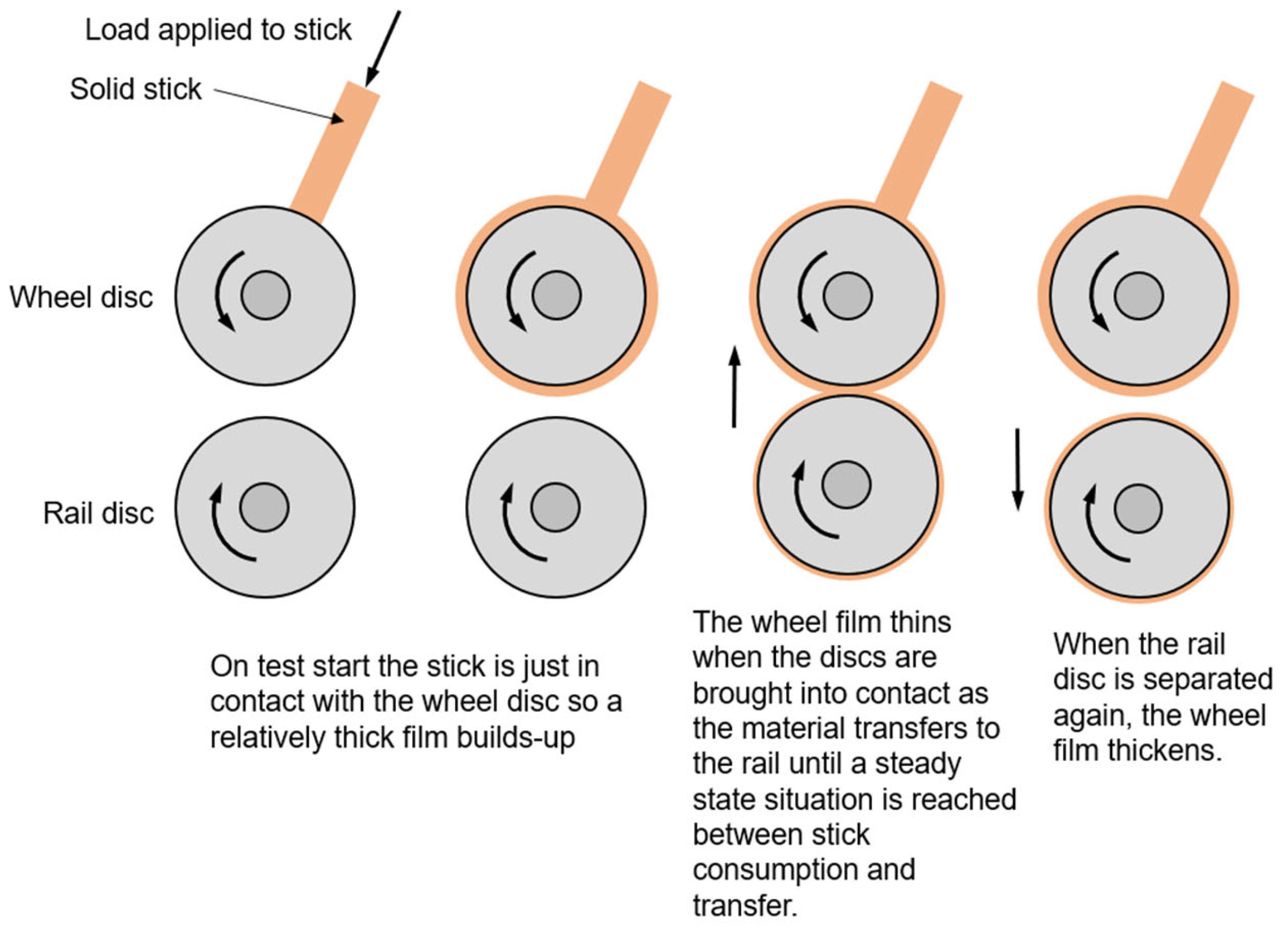
2.4. Revised Wear Test Methodology
- Product constantly applied to wheel disc.
- Discs out of contact for 2000 cycles (300 s) to allow product layer to form; discs in contact for 1000 cycles (150 s). Repeat 6 times.
- More severe contact conditions, 1500 MPa max pressure, 10% creep at 400 RPM. Discs are cooled in air flow.
- Coefficient of traction and creepage were monitored throughout the test. Mass loss of both product and test discs (post cleaning with acetone in an ultrasonic bath) is also recorded, using weighing scales with µg resolution.
- At least 3 repeats are recommended. Each trial had at least three repeats; however, some results had to be discounted as faults were uncovered (i.e., a significant misalignment between product and disc).
- Low wheel disc mass loss;
- Low rail disc mass loss;
- Low product consumption—by volume (mm3).
3. Results
3.1. EN 15427-2-1:2022 Retentivity Tests
3.2. Drawbacks of EN 15427-2-1:2022 Testing
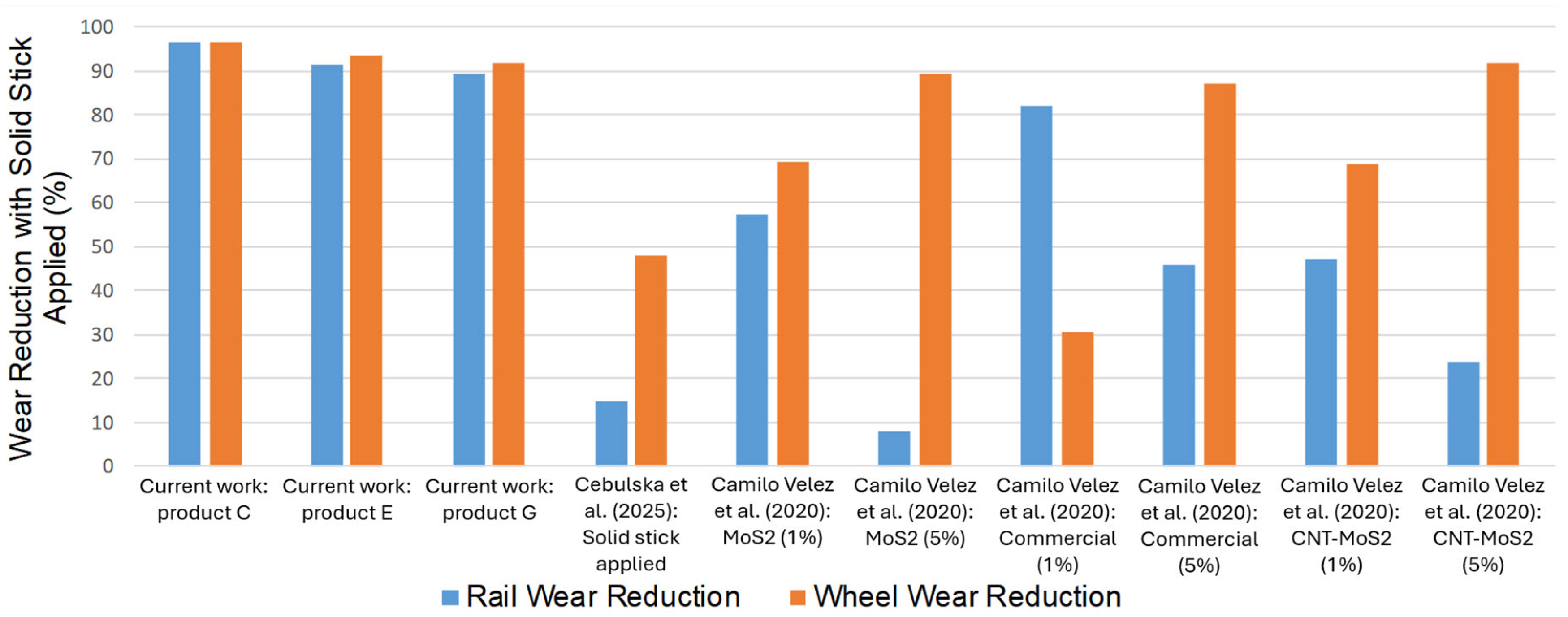
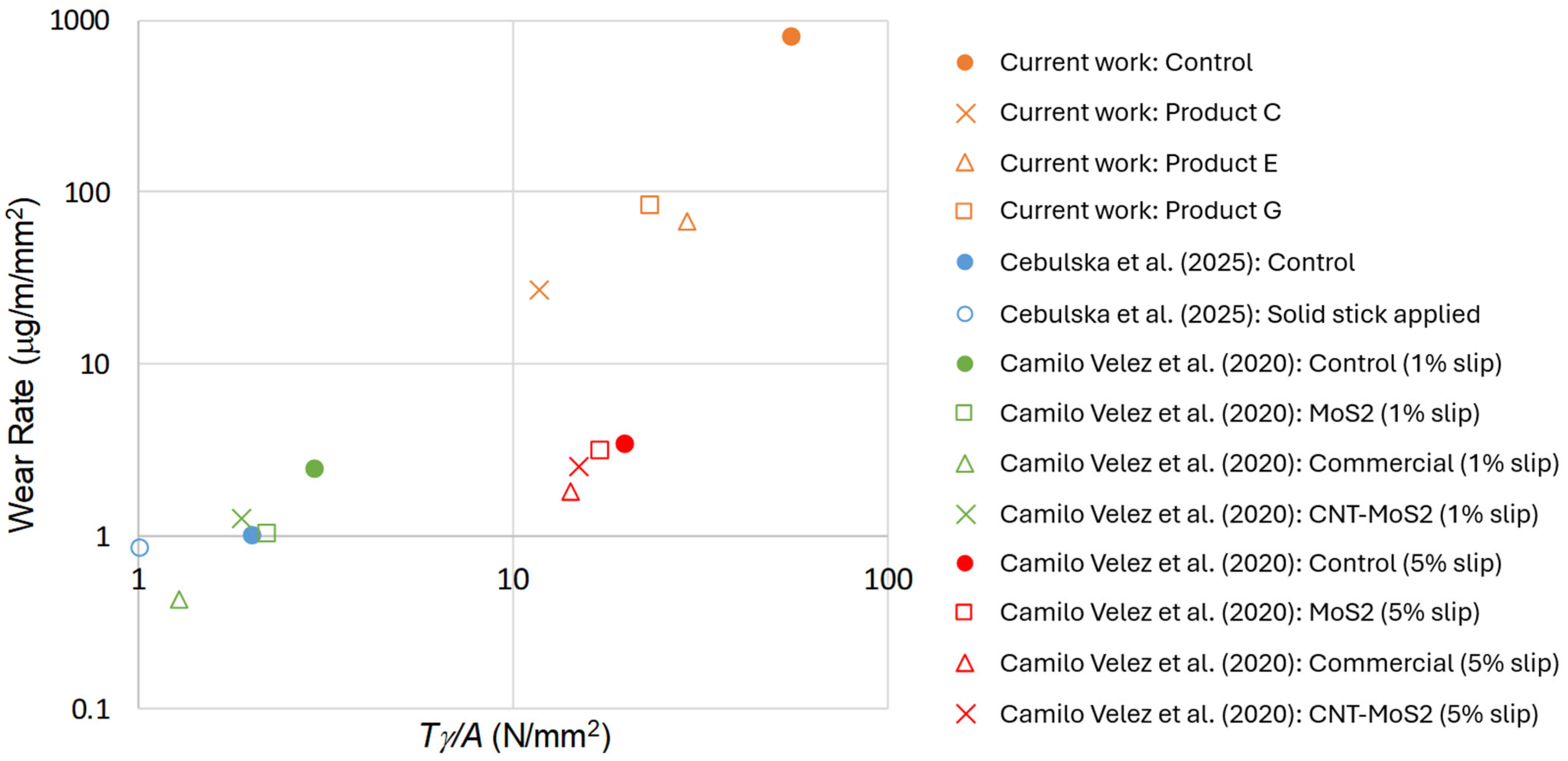
3.3. Revised Wear Tests
3.4. Drawbacks of Revised Testing
3.5. The Effect of Specimen Temperature on Product Performance
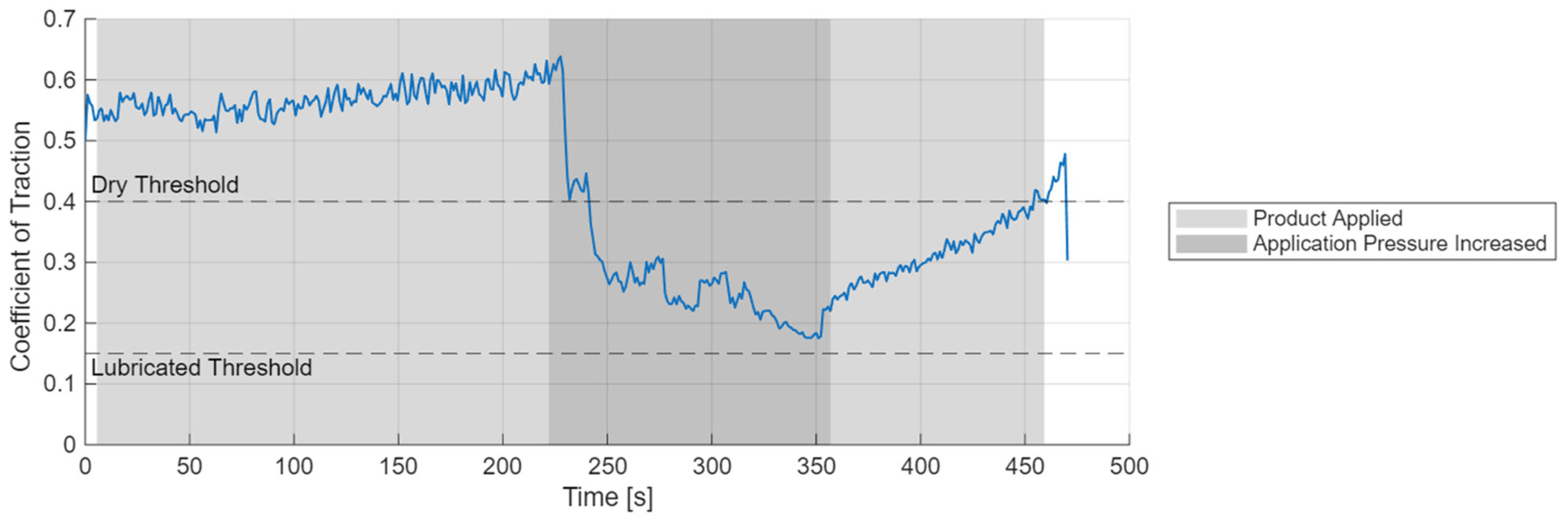
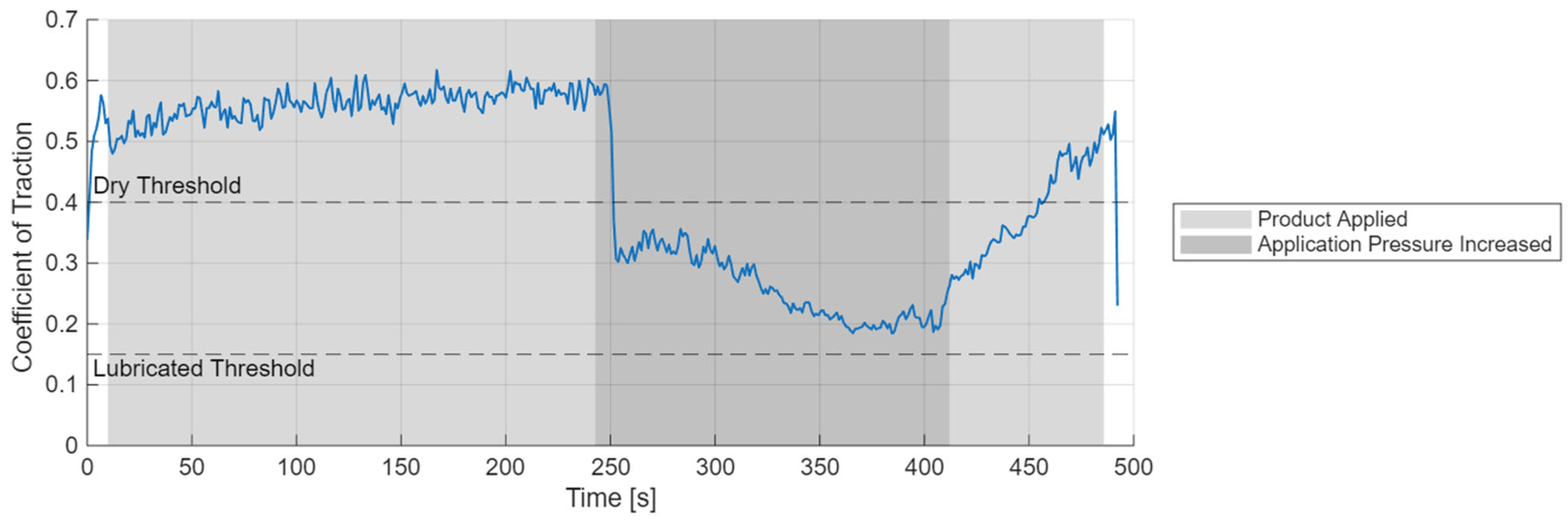
3.6. The Effect of Application Pressure on Product Performance
4. Further Work
- Run all trials at the manufacturer’s recommended application pressure.
- Redesign of applicator to improve control of application pressure (mass/lever-based system).
- Perform all trials for all products included in the trial.
- Improve confidence in results:
- Run trials until a defined statistical certainty is reached (or maximum trial number, whichever is lower).
- At least three successful trials for each product.
- Record specimen roughness at the following times:
- Prior to the test.
- After the test (including product layer).
- After the test (with product layer cleaned off).
- Ensure a full product layer has been built up.
- Consider a longer initial product application without specimens in contact.
- Consider a visual check of product layer integrity and product wear scars, prior to putting discs into contact.
- Consider an increase in the number of contact periods, from 6 to 10 (this may be impractical/dangerous for non-lubricated control runs).
- Include additional tests with a clean wheel specimen running against a treated rail specimen, and investigate the “retentivity” of the product.
- Define a method of quantifying friction coefficient values for the revised tests.
- Ensure a full product layer has been built up prior to the retentivity phase of the test.
- Once the application period has been performed, pause the test with discs out of contact, and perform a visual check of the product layer and product wear scars before continuing to the retentivity phase.
5. Conclusions
Author Contributions
Funding
Data Availability Statement
Conflicts of Interest
References
- Carreiro Rocha, R.; Ewald, H.; Bavaresco Rezenda, A.; Tamara Fonseca, S. Using twin discs for applications in the railway: A systematic review. J. Braz. Soc. Mech. Sci. Eng. 2023, 45, 191. [Google Scholar] [CrossRef]
- Wang, W.-J.; Liu, T.F.; Wang, H.Y.; Liu, Q.Y.; Zhu, M.H.; Jin, X.S. Influence of friction modifiers on improving adhesion and surface damage of wheel/rail under low adhesion conditions. Tribol. Int. 2014, 75, 16–23. [Google Scholar] [CrossRef]
- Voltr, P.; Lata, M. Transient wheel–rail adhesion characteristics under the cleaning effect of sliding. Veh. Syst. Dyn. 2015, 53, 605–618. [Google Scholar] [CrossRef]
- Biazon, L.; Ferrer, B.P.; Toro, A.; Cousseau, T. Correlations between rail grease formulation and friction, wear and RCF of a wheel/rail tribological pair. Tribol. Int. 2021, 153, 106566. [Google Scholar] [CrossRef]
- Leiva-Mateus, J.E.; Santa-Marin, J.F.; Buitrago-Sierra, R.; Mesa Grajales, D.H.; Geffroy, E. Rheological and tribological evaluation of friction modifiers for wheel-rail applications. Lubr. Sci. 2022, 34, 537–546. [Google Scholar]
- Kvarda, D.; Galas, R.; Omasta, M.; Hartl, M.; Krupka, I.; Dzimko, M. Shear properties of top-of-rail products in numerical modelling. Proc. Inst. Mech. Part. F J. Rail Rapid Transit. 2023, 23, 796–805. [Google Scholar] [CrossRef]
- Gallardo-Hernandez, E.A.; Lewis, R. Twin disc assessment of wheel/rail adhesion. Wear 2008, 265, 1309–1316. [Google Scholar] [CrossRef]
- Wang, W.-J.; Zhang, H.F.; Wang, H.Y.; Liu, Q.Y.; Zhu, M.H. Study on the adhesion behavior of wheel/rail under oil, water and sanding conditions. Wear 2011, 271, 2693–2698. [Google Scholar] [CrossRef]
- Arias-Cuevas, O.; Li, Z.; Lewis, R. A laboratory investigation on the influence of the particle size and slip during sanding on the adhesion and wear in the wheel–rail contact. Wear 2011, 271, 14–24. [Google Scholar] [CrossRef]
- Fletcher, D.I.; Beynon, J.H. Development of a machine for closely controlled rolling contact fatigue wear testing. J. Test. Eval. 2000, 28, 267–275. [Google Scholar] [CrossRef]
- Fletcher, D.I.; Beynon, J.H. The effect of intermittent lubrication on the fatigue life of pearlitic rail steel in rolling-sliding contact. Proc. Inst. Mech. Part. F J. Rail Rapid Transit. 2000, 214, 145–158. [Google Scholar] [CrossRef]
- Seo, J.-W.; Jun, H.-K.; Kwon, S.-J.; Lee, D.-H. Rolling contact fatigue wear of two different rail steels under rolling–sliding contact. Int. J. Fatigue 2016, 83, 184–194. [Google Scholar] [CrossRef]
- Chen, H.; Zhang, C.; Liu, W.; Li, Q.; Chen, H.; Yang, Z.; Weng, Y. Microstructure evolution of a hypereutectoid pearlite steel under rolling-sliding contact loading. Mater. Sci. Eng. A 2016, 655, 50–59. [Google Scholar] [CrossRef]
- Li, Q.; Huang, X.; Huang, W. Fatigue property microstructure deformation behavior of multiphase microstructure in a medium-carbon bainite steel under rolling contact condition. Int. J. Fatigue 2019, 125, 381–393. [Google Scholar] [CrossRef]
- Li, Q.; Guo, J.; Zhao, A. Effect of upper bainite on wear behaviour of high-speed wheel steel. Tribol. Lett. 2019, 67, 121. [Google Scholar] [CrossRef]
- Li, Q.; Zhang, C.; Chen, H.; Chen, H.; Yang, Z. Microstructural evolution of a hypoeutectoid pearlite steel under rolling-liding contact loading. J. Iron Steel Res. Int. 2016, 23, 1054–1060. [Google Scholar] [CrossRef]
- Liu, C.; Liu, P.; Pan, J.; Chen, C.; Ren, R. Effect of original microstructure on wear property of ER9 wheel steel. Ironmak. Steelmak. 2021, 48, 133–141. [Google Scholar] [CrossRef]
- Shi, X.; Yan, Q.; Zhang, X.; Diao, G.; Zhang, C.; Hong, Z.; Wen, Z.; Jin, X. Hardness matching of rail/wheel steels for high-speed train based on wear rate and rolling contact fatigue performance. Mater. Res. Express 2019, 6, 066501. [Google Scholar] [CrossRef]
- Lewis, R.; Gallardo, E.A.; Cotter, J.; Eadie, D.T. The effect of friction modifiers on wheel/rail isolation. Wear 2011, 271, 71–77. [Google Scholar] [CrossRef]
- Lewis, R.; Dwyer-Joyce, R.S.; Lewis, J. Disc machine study of contact isolation during railway track sanding. Proc. Inst. Mech. Eng. Part. F J. Rail Rapid Transit. 2003, 217, 11–24. [Google Scholar] [CrossRef]
- Hardwick, C.; Lewis, S.; Lewis, R. The effect of friction modifiers on wheel/rail isolation at low axle loads. Proc. Inst. Mech. Eng. Part. F J. Rail Rapid Transit. 2013, 228, 768–783. [Google Scholar] [CrossRef]
- EN 15427-2-1:2022; Wheel/Rail Friction Management—Part 2-1: Properties and Characteristics—Flange Lubricants. British Standards Institution: London, UK, 2022.
- EN 16028:2012; Railway Applications—Wheel/Rail Friction Management—Lubricants for Trainborne and Trackside Applications. British Standards Institution: London, UK, 2013.
- Telliskivi, T.; Olofsson, U. Contact mechanics analysis of measured wheel—Rail. Proc. Inst. Mech. Eng. Part. F J. Rail Rapid Transit. 2001, 215, 65–73. [Google Scholar] [CrossRef]
- Eadie, D.T.; Hui, R. Wheel life extension with on-board solid stick flange lubrication. In Proceedings of the 14th International Wheelset Congress, Orlando, FL, USA, 17–21 October 2004. [Google Scholar]
- Eadie, D.T.; Oldknow, K.; Oka, Y.; Hui, R.; Klauser, P.; Dick, M. Effective friction control for optimization of high speed rail operations. In Proceedings of the 2010 Joint. Rail Conference, Urbana, IL, USA, 27–29 April 2010. [Google Scholar]
- Ashofteh, R.S.; Samari, F. Effect of dry lubrication to reduce wheel flange wear of railcars in railway of Iran (Case Study: Green Plour (GPIG) Passenger Train Coaches). Int. J. Railw. 2014, 7, 65–70. [Google Scholar] [CrossRef]
- Transportation Technology Center Inc. Evaluation of the Kelsan Solid Stick Lubricant Locomotive Flange Lubrication System; Transportation Technology Center Inc.: Pueblo, CO, USA, 2002. [Google Scholar]
- Jin, Y. Laboratory Evaluation of Tribological Behaviours for Wheel Flange Lubricant; LCF: Beijing, China, 1998. [Google Scholar]
- Fang, C.; Ding, Y.; Chen, J.; Zhou, W.; Guan, Y.; Zhan, S. Analysis and application of train wheel flange lubrication materials. Tribology 2024, 44, 143–153. [Google Scholar]
- Song, J.; Shi, L.; Ding, H.; Galas, R.; Omasta, M. Effects of solid friction modifier on friction and rolling contact fatigue damage of wheel-rail surfaces. Friction 2022, 10, 8. [Google Scholar] [CrossRef]
- Cebulska, W.; Bakowski, H.; Hadrys, D. The influence of selected solid lubricants on the wear of the rolling–sliding interface in the wheel–rail system according to the standard PN-EN 15427-2-1:2022. Materials 2025, 18, 1672. [Google Scholar] [CrossRef]
- Camilo Velez, J.; Carlos Cornelio, J.A.; Buitrago Sierra, R.; Santa, J.F.; Hoyes-Palacio, L.M.; Nevshupa, R.; Toro, A. Development of a composite friction modifier with carbon nano-tubes for applications at the wheel-rail interface. Adv. Compos. 2020, 29, 1–8. [Google Scholar]
- Evans, M.D.; Lewis, R. Alternative twin-disc assessment of solid stick flange lubricants. In Proceedings of the 10th International Conference on Contact Mechanics and Wear of Rail/Wheel Systems, Colorado Springs, CO, USA, 30 August–3 September 2015. [Google Scholar]


| Label | Product Description |
|---|---|
| A | MoS2-based product (medium content) |
| B | MoS2-based product (lowest content) |
| C | MoS2-based product (highest content) |
| D | High-graphite-content product #1 |
| E | Thermoplastic MoS2 and graphite-based product #1 |
| F | High-graphite-content product #2 |
| G | Thermoplastic soya-based product containing MoS2 and graphite |
| H | Thermoplastic MoS2 and graphite-based product #2 |
| Lubrication Effectiveness | Product | Number of Successful Repeat Runs | Coefficient of Traction |
|---|---|---|---|
| Effectively lubricating products μ ≤ 0.15 | C | 3 | 0.056 |
| G | 3 | 0.094 | |
| A | 2 | 0.103 | |
| Partially lubricating products 0.15 ≤ μ ≤ 0.4 | H | 3 | 0.258 |
| B | 2 | 0.332 | |
| Non-lubricating products μ ≥ 0.4 | D | 3 | 0.535 |
| E | 3 | 0.558 | |
| F | 3 | 0.562 |
| Products | C | G | A |
|---|---|---|---|
| Lubricated Coefficient of Traction at t2 | 0.056 | 0.094 | 0.103 |
| Product Response: t1−t0 (s) | 4 | 2 | 52 |
| Retentivity: t4−t2 (s) | 1502 | 484 | 1202 |
| Consumption (mm3) | 4.81 | 6.73 | 3.57 |
| Average Mass Loss | Control (1) | C (4) | E (2) | G (1) |
|---|---|---|---|---|
| Rail (g) | 4.430 | 0.152 | 0.388 | 0.467 |
| Wheel (g) | 5.426 | 0.198 | 0.358 | 0.443 |
| Product (mg) | N/A | 27.1 | 7.2 | 5.4 |
| Product (mm3) | N/A | 0.0129 | 0.0038 | 0.0046 |
Disclaimer/Publisher’s Note: The statements, opinions and data contained in all publications are solely those of the individual author(s) and contributor(s) and not of MDPI and/or the editor(s). MDPI and/or the editor(s) disclaim responsibility for any injury to people or property resulting from any ideas, methods, instructions or products referred to in the content. |
© 2025 by the authors. Licensee MDPI, Basel, Switzerland. This article is an open access article distributed under the terms and conditions of the Creative Commons Attribution (CC BY) license (https://creativecommons.org/licenses/by/4.0/).
Share and Cite
Evans, M.D.; Lee, Z.S.; Lewis, R. Twin-Disc Wear Assessment of Solid Stick Flange Lubricants. Lubricants 2025, 13, 330. https://doi.org/10.3390/lubricants13080330
Evans MD, Lee ZS, Lewis R. Twin-Disc Wear Assessment of Solid Stick Flange Lubricants. Lubricants. 2025; 13(8):330. https://doi.org/10.3390/lubricants13080330
Chicago/Turabian StyleEvans, Martin David, Zing Siang Lee, and Roger Lewis. 2025. "Twin-Disc Wear Assessment of Solid Stick Flange Lubricants" Lubricants 13, no. 8: 330. https://doi.org/10.3390/lubricants13080330
APA StyleEvans, M. D., Lee, Z. S., & Lewis, R. (2025). Twin-Disc Wear Assessment of Solid Stick Flange Lubricants. Lubricants, 13(8), 330. https://doi.org/10.3390/lubricants13080330