Abstract
This study explores the machinability of Incoloy 800HT (high temperature) under a sustainable lubrication approach, employing a twin-nozzle minimum quantity lubrication (MQL) system with groundnut oil as a green cutting fluid. The evaluation focuses on key performance indicators, including surface roughness, tool flank wear, power consumption, carbon emissions, and chip morphology. Groundnut oil, a biodegradable and nontoxic lubricant, was chosen to enhance environmental compatibility while maintaining effective cutting performance. The Taguchi L16 orthogonal array (three factors and four levels) was utilized to conduct experimental trials to analyze machining characteristics. The best surface quality (surface roughness, Ra = 0.514 µm) was obtained at the lowest depth of cut (0.2 mm), modest feed (0.1 mm/rev), and moderate cutting speed (160 m/min). The higher ranges of flank wear are found under higher cutting speed conditions (320 and 240 m/min), while lower wear values (<0.09 mm) were observed under lower speed conditions (80 and 160 m/min). An entropy-integrated multi-response optimization using the MOORA (multi-objective optimization based on ratio analysis) method was employed to identify optimal machining parameters, considering the trade-offs among multiple conflicting objectives. The entropy method was used to assign weights to each response. The obtained optimal conditions are as follows: cutting speed = 160 m/min, feed = 0.1 mm/rev, and depth of cut = 0.2 mm. Optimized outcomes suggest that this green machining strategy offers a viable alternative for sustainable manufacturing of difficult-to-machine alloys like Incoloy 800 HT.
1. Introduction
Incoloy 800 HT material is a Ni-based high-temperature alloy and is widely used in aircraft turbine blades, steam tubing in nuclear power plants, and heat exchanger in the petroleum industry due to its specific qualities such as demonstrating resistance to carburization and oxidation while retaining sufficient yield strength at high temperature and an improved load capacity to thermal shock [1]. It exhibits exceptional mechanical strength, superior oxidation resistance, and excellent metallurgical stability, making it a preferred material for high-temperature industrial applications [2,3]. However, these same properties combined with its low thermal conductivity make Incoloy 800HT difficult to machine, leading to challenges including rapid tool wear, higher cutting loads, and poor surface finish.
To overcome these difficulties, current machining processes have shifted toward long-term cooling and lubrication solutions, with MQL receiving major attention. MQL includes applying a very tiny quantity of lubricant (10–100 L/h) directly to the cutting zone, offering a compromise between dry and wet machining [4]. This approach offers several advantages, including reduced environmental impact, lower operational costs, and longer tool life, as well as enhanced surface integrity in difficult-to-machine materials such as Incoloy 800HT [5]. Numerous experimental studies have reported that MQL is very effective to minimizing friction at cutting zones, preventing temperature growth and adhesion, enhancing tool longevity, and promoting better surface finish across various traditional machining processes, including turning, milling, grinding, and drilling processes [6,7,8,9,10].
The competency of MQL in machining depends on cutting parameters value, type of lubricating oil, flow rate, nozzle type, nozzle orientations, nozzle tip to cutting zone distance, air pressure, etc. Many researchers [11,12] revealed that the optimized cutting parameters and the MQL operating constraints such as coolant type, coolant volume, coolant flow rate, air pressure, pulse mode frequency, and the position of nozzle towards cutting zone significantly influence machining performance by lowering tool wear, cutting temperature, and cutting forces. The adoption of green lubricating fluids (such as vegetable oils, fatty acids, and synthetic esters) in MQL systems has helped to mitigate the negative environmental effect of conventional lubricating fluids. In addition to being environmentally benign, these fluids must have good thermal conductivity to properly disperse heat and cutting tool generated during machining. Poor heat transfer capabilities can cause recessive heat retention in the workpiece. As highlighted by Bosewell et al. [13], MQL fluids should exhibit high lubricity, thermal and chemical stability, and biodegradability to support sustainable machining practices. Several MQL lubricants have been tested to evaluate their effectiveness in enhancing machinability, particularly in machining Ni-base alloys. In recent years, the usage of vegetable oils as lubricants is attaining popularity in various machining applications due to their eco-friendly and biodegradable characteristics [14]. Vegetable oils are predominantly derived from the seeds of various plants, with sustainable sources including coconut, soybean, sunflower, ground nut, olive, rapeseed, and palm [14,15]. In some studies [14,16], it was found that vegetable oil was more biodegradable than mineral oil, thus making it a good candidate for replacing mineral oil and other conventional fluids in MQL systems. Saleem et al. [17] examined the performance of sunflower and castor oils in turning Inconel 718 alloys using MQL. The performance of these vegetable oils was also compared with dry machining. Sunflower oil outperformed both castor oil and dry machining. Best surface finish (0.43 μm) was attained at the cutting speed of 70 m/min, and feed rate of 0.168 mm/rev under sunflower oil-assisted MQL. Sarkar and Datta [18] implemented coconut oil as a cutting fluid in machining Inconel 718 under dry, MQL, and carbon nanotube MQL conditions. Both MQL and carbon nanotube MQL methods successfully reduced the tool tip temperature and flank wear in comparison to dry machining. Ekinovic et al. [19] employed rapeseed oil as a cutting lubricant for MQL in turning Nimonic C-263 using coated and uncoated carbides tools. The implementation of MQL led to substantial decrease (38%) in chip temperature compared to dry cutting. Furthermore, the use of rapeseed oil resulted in a 20% drop in cutting forces, indicating a corresponding decrease in energy uses when MQL with rapeseed oil is utilized. Tazehkandi et al. [20,21] utilized biocut biodegradable vegetable oil in machining Inconel alloys. The performance of the spray mode lubricant was compared with flood mode cooling and found a significant reduction in cutting forces, surface roughness, and tool tip temperature with spray mode cooling system. Zhang et al. [22] implemented Bescut 173-based MQL environment in machining Inconel 718 alloy and examined the performance under dry conditions. The MQL-enabled machining provided 1.57 times greater tool life in contrast to dry conditions. It was revealed that the Biscut 173 fluid helped reduce the intensity of cutting forces due to its outstanding cooling and lubricating characteristics. Tamang et al. [23] investigated the machinability of Inconel-825 by comparing dry machining with MQL utilizing mineral oil. MQL demonstrated notable advantages in machining like reduced tool wear (16.57%), lowered power consumption (8.47%) and reduced surface roughness (10.41%).
Furthermore, MQL operating factors (flow rate, air pressure, number of nozzles, pulse duration, orientation, and the location of nozzles) have a great impact on machinability of the material being machined [24]. Single nozzle MQL was commonly employed in machining research. However, there is potential to utilize multi-nozzle MQL setup to improve the cooling and lubricating capability of MQL technology. Sohrabpoor et al. [25] discovered that directing MQL spray onto both the flank and rake sides of the cutting tool enhanced lubrication efficacy in machining-hardened AISI 4340 steels. Mia and Dhar [26,27] analyzed the consequences of nozzle position in turning Ti-alloys. The twin-nozzle MQL provided better lubrication in comparison to single nozzle. Thamizhmanii and Rosli [28] applied sunflower oil as a lubricant at varying flow rates (12.5, 25, and 37.5 mL/h) for milling Inconel 718 and assessed its performance relative to dry milling conditions. The highest flow rate yielded the lowest roughness, outperforming the lower flow rates. Overall, sunflower oil reduced surface roughness by 32.65% and tool wear by 29.2% when comparing the lowest and highest flow rates. Cai et al. [29] conducted an end milling experiments using the MQL system. The flow rate was varied from 50 to 200 mL/h, and a decreasing coefficient of friction was observed with increasing flow rate. The minimum cutting force was found at s flow rate of 150 mL/h. In another study, Cai et al. [30] used 100–500 mL/h flow rate to examine variation in cutting temperature during end milling of AISI D2 steel. The optimal flow rate was found to be 300 mL/h.
The role of cutting tool used in machining nickel base alloy is very important. Many researchers have implemented PVD (physical vapour deposition) and CVD (chemical vapour deposition) coated carbide insert in machining nickel base alloys. Yıldırım et al. [31] studied the machinability of Inconel 625 alloy using PVD applied AlTiN and TiAlN-TiN coated cutting tools. At the cutting speed of 80 m/min and above, the TiAlN-TiN-coated tool performed better than the AlTiN-coated tool. Using the TiAlN-TiN-coated tool at a tool feed of 0.075 mm/rev resulted in the highest tool life and lowest surface finish. Kamata and Obikawa [32] utilized three different cutting tools, namely TiCN-Al2O3-TiN (CVD), TiN-AlN (PVD), and TiAlN (PVD), in the finish turning of Inconel 718 alloy. TiCN-AlO3-TiN (CVD) displayed the best tool life at cutting speed of 60 m/min, whereas TiN-AlN (PVD) tool produced the best surface finish. Polvorosa et al. [33] performed machining on two super alloys, Inconel 718 and Waspaloy, by using standard uncoated cemented carbide inserts and revealed that tool wear progression was consistent across cutting passes. Waspaloy exhibited lower flank wear despite similar cutting force. Jindal et al. [34] evaluated the relative merits of carbide tools coated with PVD-applied TiN, TiCN, and TiAlN in turning Inconel 718 alloy. Experiments were executed at cutting speeds of 46 and 76 m/min, while the tool feed and the cutting depth were kept constant at 0.15 mm/rev and 1.5 mm, respectively. Among the tested coatings, tools with TiAlN and TiCN outperformed those with TiN coatings at both speed levels. In another study, Prengel et al. [35] carried out turning tests on Inconel 718 using different PVD-coated carbide cutting tools with coolant at cutting speeds of 61 and 76 m/min. The multilayered (TiAlN) tool demonstrated superior concert compared to both AlTiN-monolayer and TiN/TiCN/TiAlN-multilayer coatings, especially at a speed of 76 m/min. Bhatt et al. [36] found that a TiCN/Al2O3/TiN-coated tool provided the greatest wear resistance at a speed of 100 m/min, while at a lower speed of 50 m/min, the uncoated tool exhibited better performance.
The role of cutting parameters in turning nickel base alloy is very important and crucial for achieving higher productivity at lower cost. Optimal levels of cutting parameters are essential for achieving higher productivity in machining. Various optimization methodologies were used so far to predict the optimal level of machining parameters in machining nickel base alloys. Palanisamy et al. [37] optimized turning parameters for Incoloy 800H using cryogenically treated tools through Taguchi-based Grey Relational Analysis (GRA) and Response Surface Methodology (RSM). The optimal conditions were identified as 30 m/min speed, 0.03 mm/rev feed, and 0.75 mm cutting depth. Prasad et al. [1] also implemented Taguchi–Grey relational analysis method to optimize cutting parameters (speed, feed rate, depth of cut) in high-speed dry turning of Inconel 800. The optimal values of these cutting parameters were 175 m/min, 0.15 mm/rev, and 0.6 mm, respectively. Frifita et al. [38] optimized the cutting parameters in turning Inconel 718 using RSM. The estimated optimum levels of cutting parameters (nose radius, cutting speed, and feed rate) were found to be 0.4 mm, 70 m/min, and 0.09 mm/rev. Panigrahi et al. [39] utilized GRA-PSO optimization approach to predict the optimal level of speed, feed, and depth of cut in dry turning of Incoloy 800. Jovicic et al. [40] optimized input variables during dry turning of Inconel 601 using a genetic algorithm optimization. It was stated that the optimal combination of input parameters changes based on how important each response parameter is chosen. Larger corner radius, square shaped insert, and smaller approach angles generally enhance machining performance.
Based on literature survey, the MQL technique offers substantial effectiveness in precisely delivering mist lubricant to the cutting zone in several metal-machining processes. Furthermore, the properties of the lubricant used in MQL greatly influence its cooling and lubrication performance. To support sustainable machining, MQL lubricants should also be environmentally friendly. Groundnut oil, an eco-friendly and biodegradable lubricant, has been rarely explored as a cutting lubricant in MQL-based machining. Additionally, the use of twin-nozzle MQL systems in machining nickel-based alloys has been scarcely reported. Moreover, from a sustainability perspective, power consumption and carbon emission are critical factors; however, they have received limited attention in the existing literature. In this research, these aspects were thoroughly examined alongside conventional performance measures such as tool flank wear, surface roughness and chip morphology. Previous studies have predominantly used optimization techniques such as grey relational analysis, response surface methodology, and genetic algorithm; however, there remains considerable potential for applying other advanced methods. To address this, the present work employs the entropy-weighted MOORA method for process optimization. In summary, this study addresses several key machinability indicators, including surface roughness, flank wear, power consumption, carbon emission, and chip morphology, to comprehensively evaluate the machining behaviour of Incoloy 800HT using groundnut oil in a twin-nozzle MQL system.
2. Materials and Methodology Details
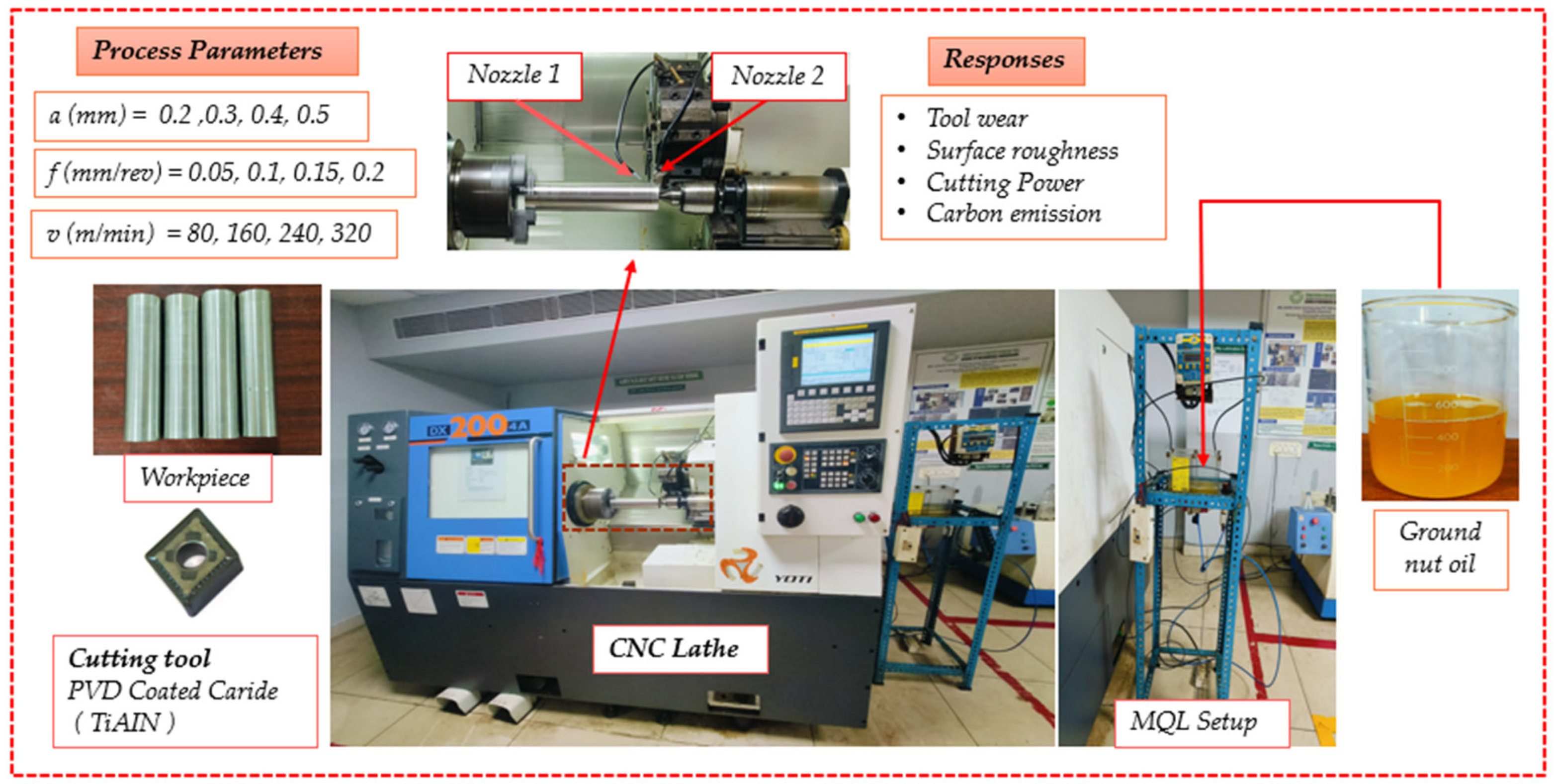
The cylindrically shaped Incoloy 800 HT (220 mm length and 60 mm diameter) was selected as a workpiece material because of its several applications in aircraft, turbine, and heat exchangers industries. The specimen size was selected based on the length-to-diameter (L/D) ratio. According to Bhandarkar et al. [41], the L/D ratio should be less than 4 to achieve more stable machining. A higher L/D ratio can induce chattering and lead to poor dimensional accuracy. WIDIA manufactured PVD-coated (AlTiN) carbide tool (CNMG120408UF) was utilized for turning the workpiece on Jyoti CNC lathe (Dx 200-4A). The turning holder was selected based on the ISO designation of the cutting insert. In the present study, a C type insert was used; therefore, a WIDIA make PCLNR 2525 M12 holder was chosen to accommodate this insert. The geometry of the cutting tool includes a 95° approach angle, a 0.8 mm nose radius, an 80° included angle, and a −6° rake angle. The tool overhang length is 50 mm. A Taguchi L16 design of experiments (DOE) with 3 factors at 4 levels each was used to carry out the experiments. The selected factors were depth of cut (a), feed (f), and cutting speed (v). The values for of each factor are presented in Table 1. These factors were chosen based on previously published literature and the manufacturer’s recommendations. The cutting environment was selected as air mist groundnut oil, supplied into cutting zone via twin-nozzle MQL. Commercially available virgin groundnut oil is an eco-friendly lubricant used in several tribology studies. The viscosity and thermal conductivity of the groundnut oil were measured at 30 °C using Brookfield viscometer (LVDV-1) and Transient Hot Wire-L2 instruments, respectively. The obtained viscosity and thermal conductivity were 29.78 cPa and 0.596 W/mK, respectively. In the twin-nozzle MQL arrangement, the 1st nozzle was positioned beside the principal flank at an angle of 45 ± 5° from the tool–holder axis, while the 2nd nozzle was placed vertically above the tool tip (with a positional error of ±5°), as shown in Figure 1. Many research papers have reported similar nozzle angles in machining [42,43]. The distance between the tip of the tool and the nozzles was maintained at approximately 25–30 mm. Many studies reported a similar distance between the tip of the tool and nozzles in the turning process [43,44,45]. Additionally, pilot tests were executed to identify the optimal flow rate of the MQL system; three different flow rates 30, 40, and 50 mL/h, were tested under fixed conditions of 160 m/min cutting speed, 0.2 mm depth of cut, and 0.1 mm/rev feed. The flank wear at 50 mL/h was found to be 1.24% lower than at 40 mL/h and 2.03% lower than at 30 mL/h. Similarly, surface roughness at 50 mL/h is 2.67% lower than at 40 mL/h and 3.84% lower than at 30 mL/h. Based on these results, a flow rate of 50 mL/h was selected for this study. The air pressure was kept at 6 bars to ensure efficient spraying of groundnut oil during machining. These settings are consistent with the previous study conducted by Khatai et al. [46] and Rajashree et al. [47].

Table 1.
Details of experimental attributes.
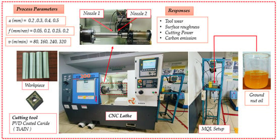
Figure 1.
Research plan and experimental setup.
In each test, key factors including surface roughness (Ra), flank wear (VBc), cutting power (Pc), and carbon emission (Ce) were systematically recorded. The roughness was measured at five individual locations on the machined surface using the Zeiss Handysurf+ Portable instrument, and the mean of these five readings was reported. According to ISO 4287, the satisfactory Ra were ≥1.6 µm [48]. Flank wear on the tool was measured using an Olympus STM 6 microscope. Additionally, Scanning Election Microscopy (SEM) and Energy Dispersive Spectroscopy (EDS) tests were executed to investigate the mechanism of tool wear. The power consumption was recorded using a 3-Phase multi-function energy metre (Model-EMT 34, RISH Delta Energy, Rishab Instruments Limited, Nashik, India). Carbon emissions from the cutting process are primarily determined by energy consumption. For a full machining cycle, emissions are estimated by taking the multiplication of total power consumed and carbon emission factor. In this study, the factor of carbon emission for India’s power grid is 0.71 KgCO2/kWh [49].
Each experiment was performed using new tool tip. The cutting length for each run was kept 160 mm. The measurements of surface roughness and tool flank wear were performed after each experiment. The measurement of power consumption was performed during cutting process and at end of experiment, the data was recorded. During the cutting process, a stopwatch was used to measure cutting time. Further, carbon emission was estimated after each experiment. The research plan with experimental setup is shown in Figure 1. The measured machinability factors results were reported in Table 2.
Table 2.
Measured results of responses.
3. Results and Discussion
The results of surface roughness (Ra), flank wear (VBc), power consumption (Pc), and carbon emission (Ce) are shown in Table 2.
3.1. Discussion on Surface Roughness and Surface Texture
The surface quality of the machined part is an essential index for analyzing the machining performances in any machining research. The surface quality is quantified using the surface roughness (Ra) value. In the current study, after completion of one pass turning for a specific cutting conditions, the surface roughness was measured and reported in Table 2. The maximum Ra (1.984 µm) was obtained at the highest depth (0.5 mm) and feed (0.2 mm/rev) with the lowest speed (80 m/min). At highest depth of cut and feed, the cross-sectional area of the material that needs to be removed is higher, resulting in more friction and cutting force being required at slower cutting speed, as a result the roughest surface is obtained under these cutting conditions [50]. Similarly, the lowest Ra (0.514 µm) was obtained at the lowest depth (0.2 mm), moderate feed (0.1 mm/rev), and moderate speed (160 m/min). This is possible due to the reduction in cutting force at relatively high speed, which facilitates stable machining and results in a good finish with the lowest feed rate [48]. The feed rate of 0.2 mm/rev was not favourable for reaching a surface roughness below 1.6 µm. According to Song et al. [51], the surface roughness was enhanced at 0.2 mm/rev feed rate due to rapid enhancement in tool nose-notch wear in machining Inconel 718 alloys. The current study produced far better results than dry turning performed by Palanisamy et al. [37]. They found a minimal roughness of 1.1 µm which is 114% higher than the minimum roughness (0.514 µm) obtained under groundnut oil coupled twin-nozzle MQL. Palanisamy and Selvaraj [52] reported a minimum Ra of 1.23 µm in dry turning of Incoloy 800H. In comparison, the current study achieved 139.2% lower roughness at the same feed rate of 0.05 mm/rev. In another research on turning Incoloy 800H using a cryo-treated CVD insert [53], a minimum roughness of 0.69 µm was reported, which is 34.2% higher than the roughness achieved in the current study, despite using a lower feed. These comparative results highlight the benefits of twin-nozzle MQL with groundnut oil.
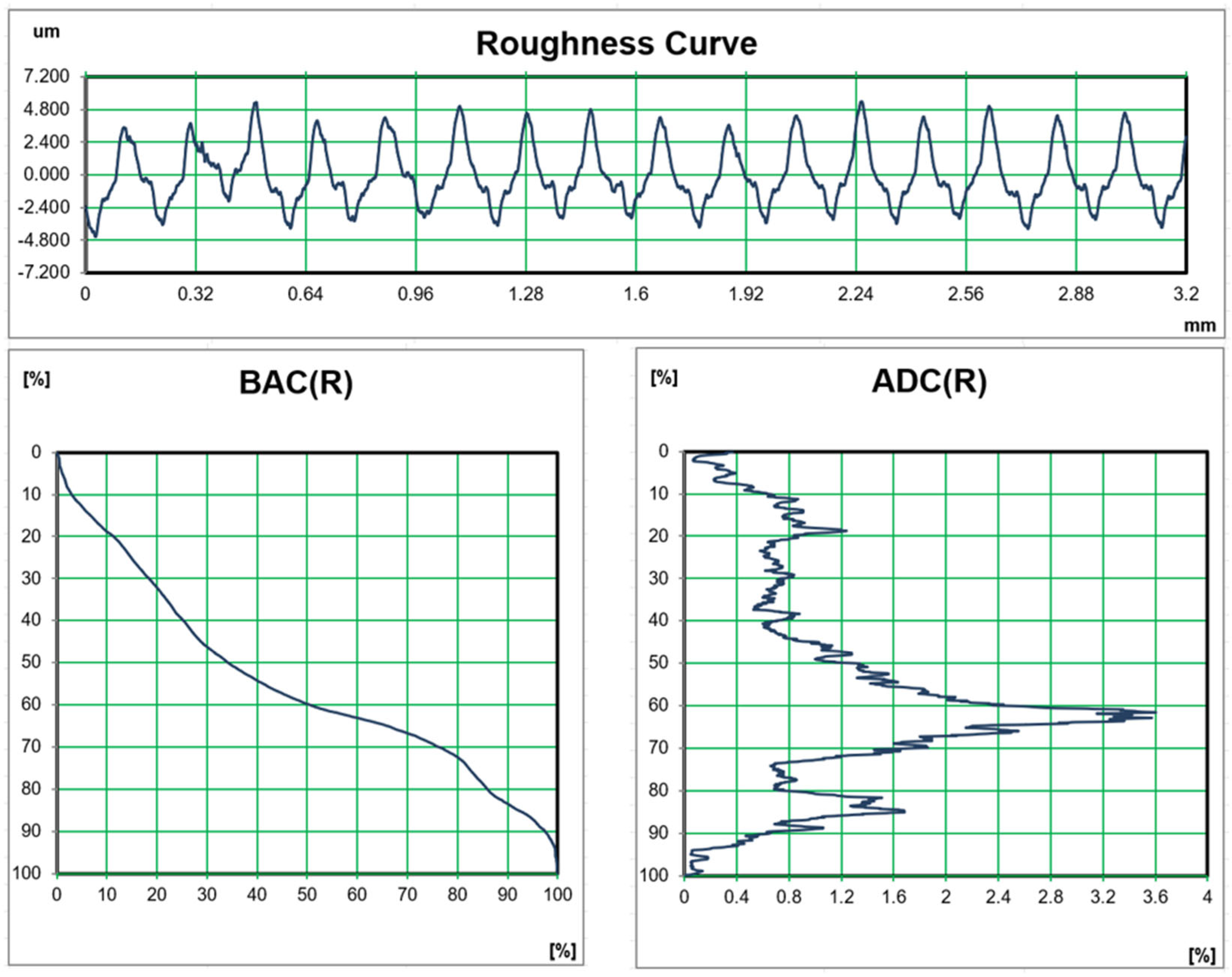
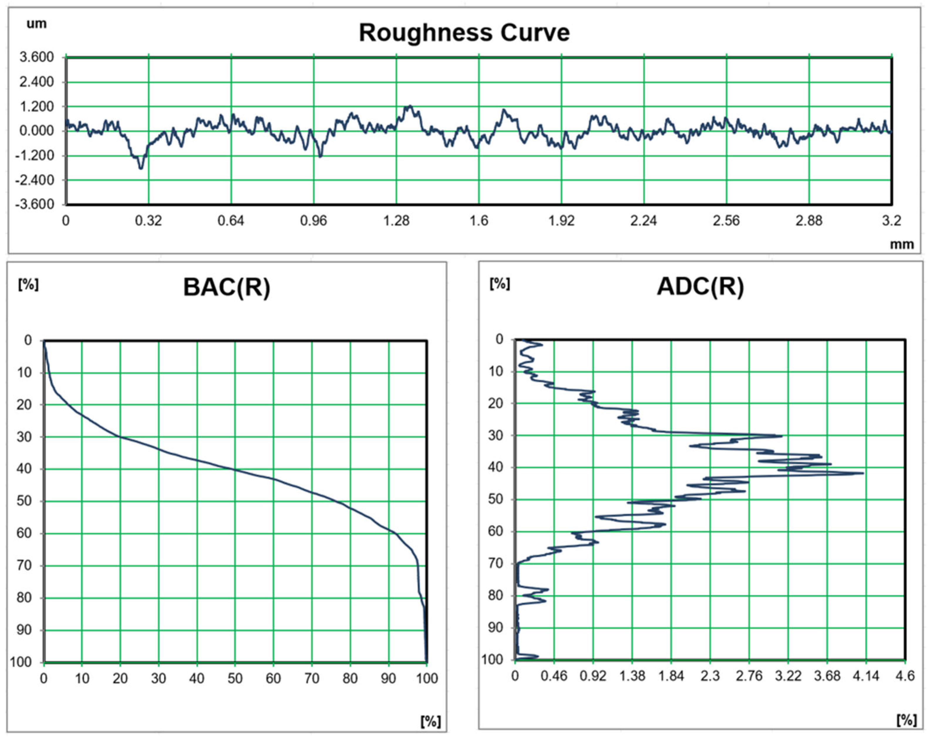
The surface texture with BAC (bearing area curve) and ADC (amplitude density curve) graphs for highest and lowest roughness of machined surface are shown in Figure 2 and Figure 3, respectively. The surface profile for the highest Ra has higher peaks and valleys in comparison to the lowest Ra profile, indicating the better smoothness of machined surface obtained in run 2. Also, at run 16, the BAC deviates from S-shape, indicating more non-uniform variations in roughness due to adhesion of fine chip’s particles to the surface [54,55]. At run 2, the BAC is closer to S-shape, indicating more uniform variations in roughness throughout the measuring length. ADC for run 16 does not followed the symmetrical shape indicating non-uniform variations in Ra, while for run 2, the ADC is closer to symmetry, resulting in better surface finish and variations on the machined workpiece [55].
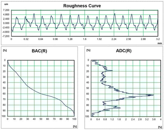
Figure 2.
Surface texture of the machined surface having the lowest Ra (Run 2: a = 0.2 mm, f = 0.1 mm/rev, and v = 160 m/min).
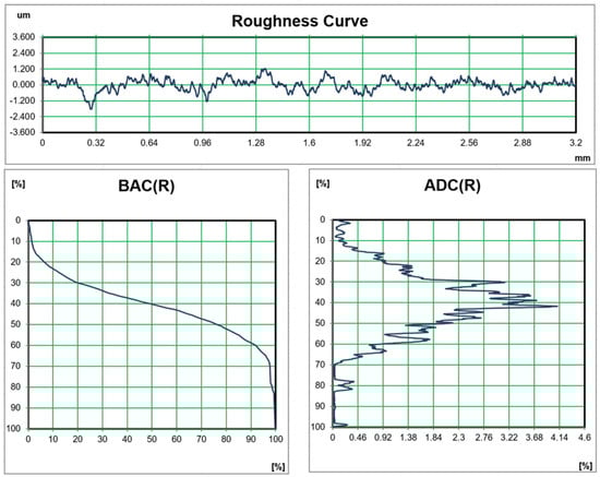
Figure 3.
Surface texture of the machined surface having the highest Ra (Run 16: a = 0.5 mm, f = 0.2 mm/rev, and v = 80 m/min).
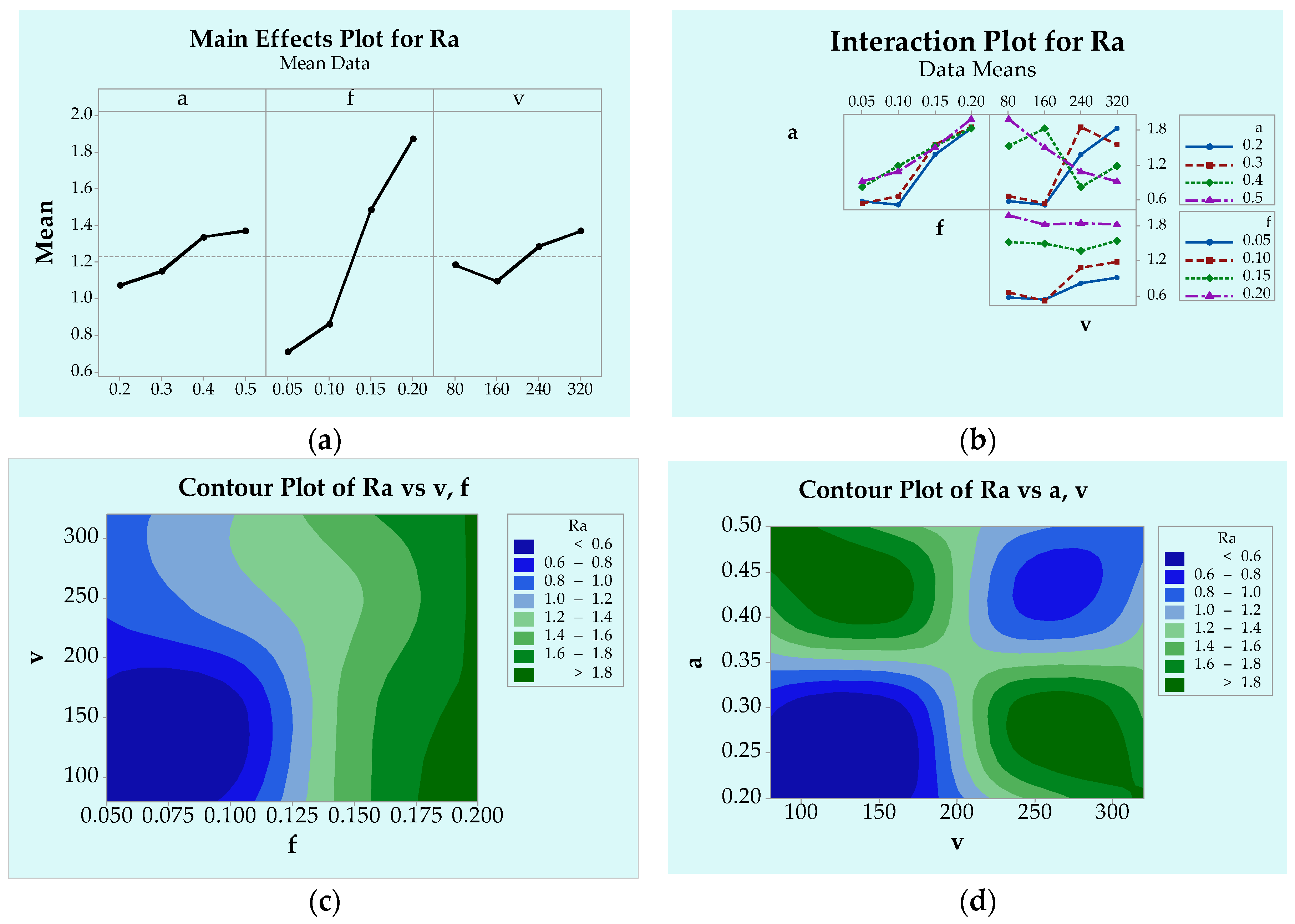
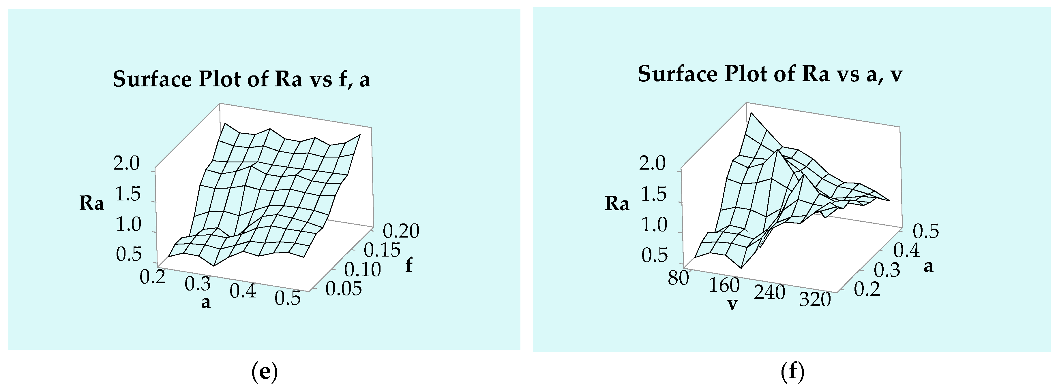
The consequences of varying machining parameters (cutting speed, feed, and depth of cut) on Ra were analyzed using statical plots and analysis of variance (ANOVA). The mean Ra increased considerably with higher rates as shown in Figure 4a. Similarly, Ra rose with increasing depth of cut, though the rate of increase was slower. The lowest mean Ra was detected at a speed of 160 m/min; however, Ra improved gradually with higher speeds due to increased tool wear and temperature. At very high speeds, the mist groundnut oil failed to penetrate the cutting zone adequately, leading to insufficient lubrication and higher friction, which resulted in increased surface roughness [56]. From the interaction plots (Figure 4b), it is evident that the interaction impact of cutting speed and depth of cut significantly impacts Ra, as curves are non-symmetrical. In contrast, the interaction effect for other parameter pairs shows near-parallel curves, addressing non-significant impacts [55]. Contour plots further revealed that the Ra increased with feed rate, irrespective of cutting speed and the depth of cut as shown in Figure 4c. Dark-green shading shown in Figure 4d, indicates higher roughness values, while lighter-shaded areas correspond to smoother surfaces. The surface quality improved when the feed rate was between 0.1 and 0.125 mm/rev, regardless of the selected speed and depth of cut. Surface plots demonstrated that the slope of Ra decreased with improving feed rate, while the effects of depth of cut were minimal as displayed in Figure 4e. Similar trends were observed with feed rate and cutting speed. From Figure 4f, Ra increased when both cutting speed and depth of cut were elevated up to their second levels. Beyond, 160 m/min speed, the Ra decreased with any feed rate used. ANOVA results (Table 3) reported that feed rate had the largest contribution to Ra, followed by cutting speed and depth of cut. All input variables were found to be relevant and significantly affected Ra. In contrast to this result, Prasad et al. [1] found higher impact of speed followed by tool feed and depth of cut in turning Inconel 800.
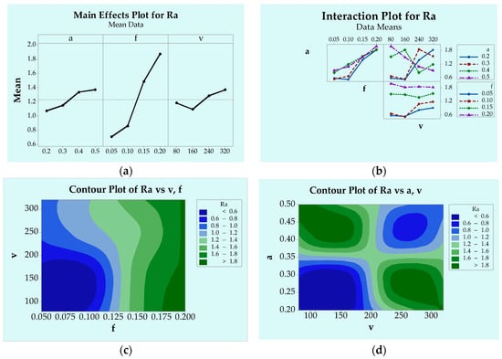
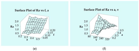
Figure 4.
Graphs showing the impact of cutting variables on Ra (a) main effects plot (b) interaction plots (c,d) contour plots (e,f) surface plots.
Table 3.
ANOVA outcomes for Ra.
3.2. Discussion on Tool Flank Wear
Tool wear is a critical factor in turning difficult-to-machine Incoloy 800HT alloys. While machining Incoloy 800HT, work hardening increases resulting in higher cutting forces and accelerating the tool wear. Moreover, due to low thermal conductivity of Incoloy 800HT, heat generated during machining is not dissipated effectively, concentrating it at the cutting zone and promoting tool degradation. However, it is essential to analyze the tool wear under different cutting conditions.
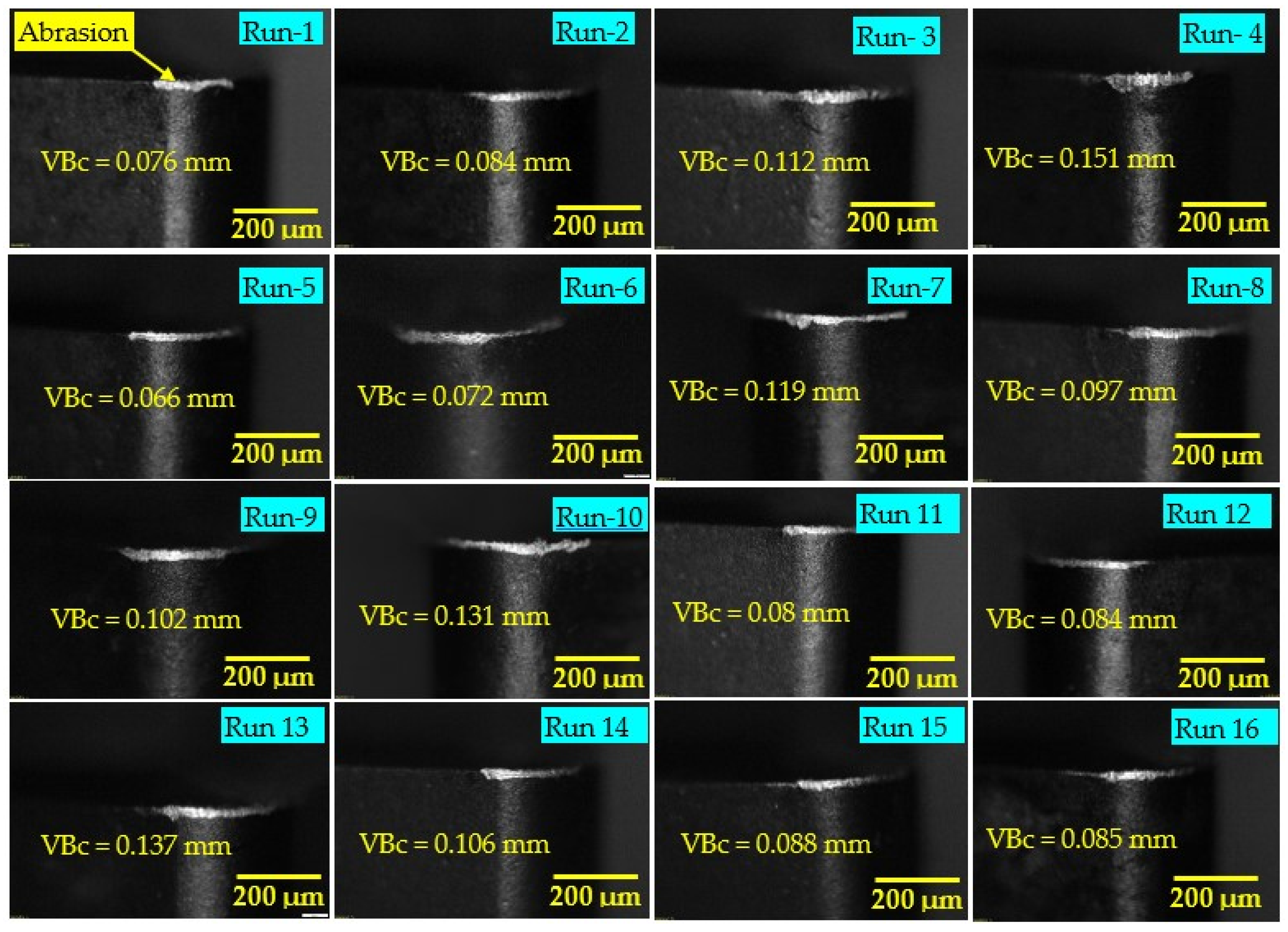
The tool wear results for 16 different experiments are shown in Table 2 and Figure 5. The minimal wear (0.066 mm) was obtained at 160 m/min speed with the lowest feed (0.05 mm/rev) and moderate depth of cut (0.3 mm). Similarly, the largest wear (0.151 mm) was obtained at the highest speed (320 m/min), highest feed (0.2 mm), and lowest depth of cut (0.2 mm). Prasad et al. [1] conducted a study on high-speed turning of Inconel 800 and reported minimal wear of 0.082 mm at a speed of 175 m/min, with a feed rate of 0.15 mm/rev and a depth of cut of 0.6 mm. The highest wear (0.379 mm) was achieved at a speed of 225 m/min with the same feed and an increase depth of cut of 1 mm. From this study, it was revealed that the higher ranges of flank tool wears are found under higher cutting speed conditions (320 and 240 m/min) due to aggressive temperature generation [57].
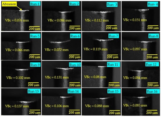
Figure 5.
Obtained flank wear images in different runs.
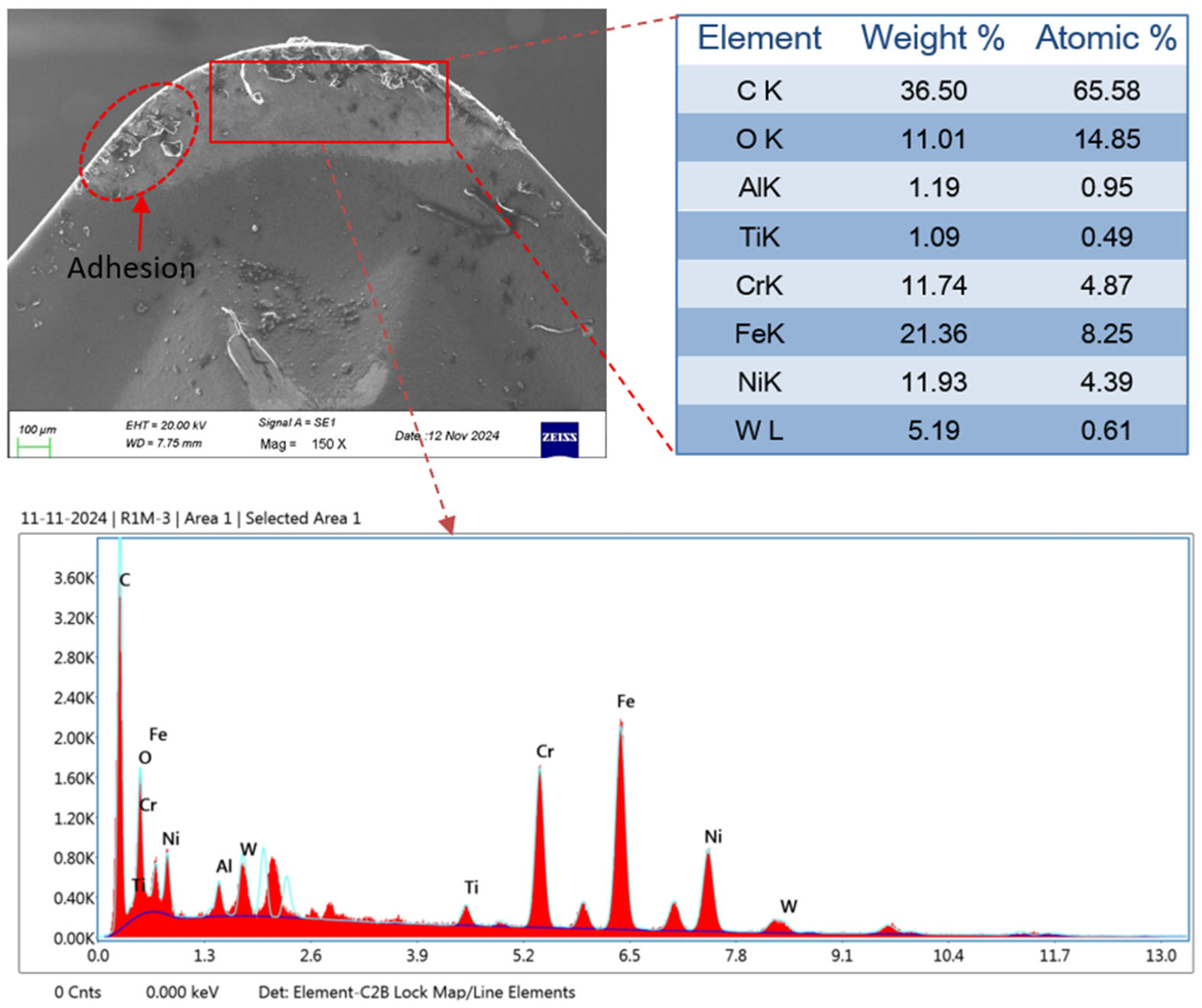
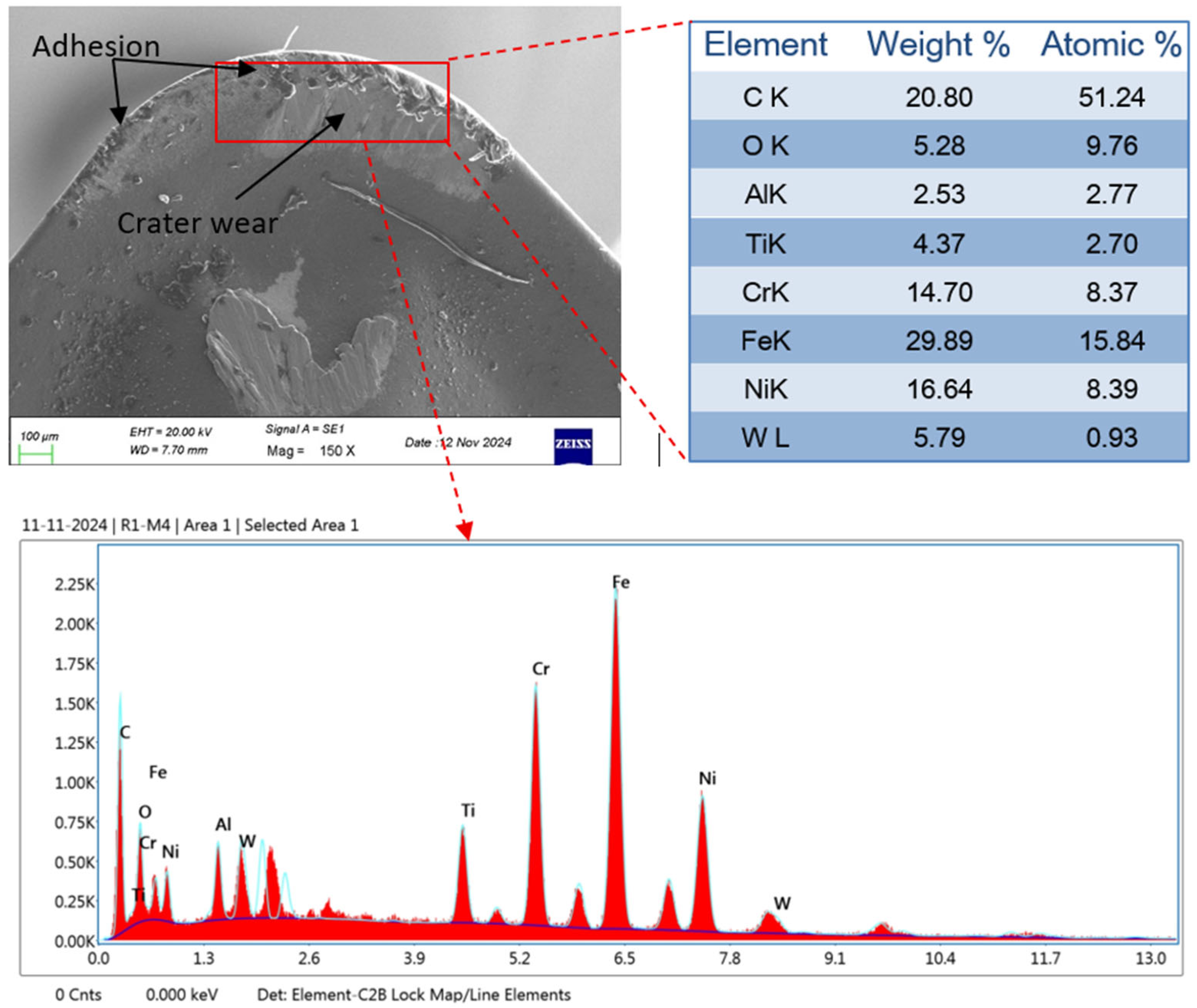
Moreover, the wear morphology for the lowest wear (Figure 6) and the highest wear (Figure 7) was discussed using a SEM (scanning electron microscope) image with an EDS (Energy Dispersive Spectroscopy) report. In both runs, chip adhesion was found near tooltip. In both EDS report, the workpiece elements Ni, Fe, Cr, and C are found in high amounts, indicating adhesion of workpiece elements over tool tip after machining. Adhesion is the most dominant phenomena found due to the high temperatures being generated during machining. Moreover, as higher temperatures generated during high-speed machining resulted in increased adhesion compared to low-speed machining [58]. This was confirmed by the EDS report, which shows a higher percentage of Ni, Fe, Cr, and C found on the more heavily worn tools. Under high-speed machining, the chip flow with relatively higher speed over tool rake surface, results in higher friction and generates crater wear, as shown in Figure 7.
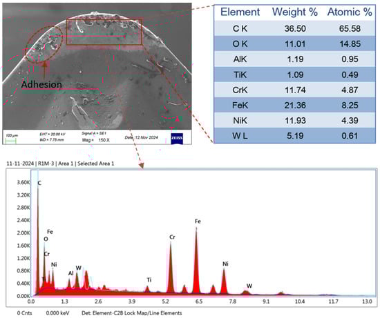
Figure 6.
SEM along with EDS report of the tool tip with the lowest wear (Run 5: a = 0.3 mm, f = 0.05 mm/rev, and v = 160 m/min).

Figure 7.
SEM along with EDS report of the tool tip with the highest wear (Run 4: a = 0.2 mm, f = 0.2 mm/rev, and v = 320 m/min).
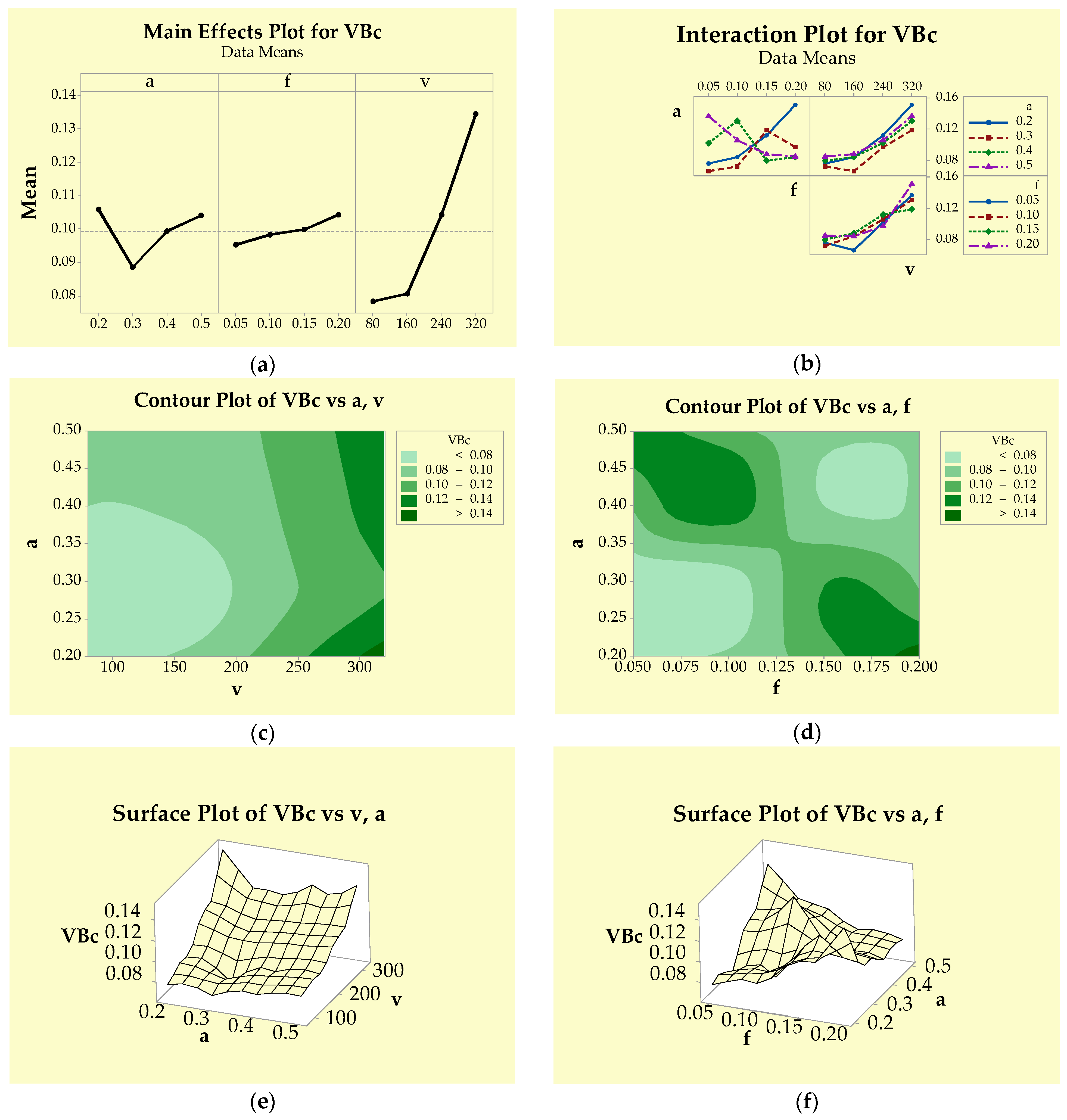
Moreover, a comprehensive analysis of the effects of cutting variables on tool wear was conducted using statistical plots (Figure 8) and ANOVA (Table 4). At lower cutting speeds (Figure 8a), tool wear increased gradually, but beyond 160 m/min, the wear accelerated sharply. Flank wear also increased as the cutting speed rose. Similarly, an increase in feed rate led to a modest rise in wear. Moreover, depth of cut also affected the tool wear considerably; beyond 0.3 mm, tool wear grew rapidly. The lowest wear occurred at a 0.3 mm depth of cut. The interaction impact between the depth of cut and feed rate on flank wear was significant as the curves were non-parallel (Figure 8b), while other factor pairs showed no significant interaction impact [55]. The contour plots (Figure 8c,d) indicated a significant increment in wear with growing speeds. Initially, as the speed was lowered, the increase in wear was also lower, indicated by the light-green colour. The colour of plots was becoming dark with the growing speeds, indicating a significant increase in wear. In Figure 8e, combinations of low feed–low depth and higher feed–high depth are associated with lower wears, while low feed-high depth and high feed–low depth produce higher wears. In Figure 8e, the slope of the curve increased with speed, confirming that wear intensified as speed increased. Other plots (Figure 8f) showed that the highest wear occurred with the combination of the lowest feed and the highest depth of cut. From the results of ANOVA (Table 4), cutting speed and depth of cut have the significant effect on tool wear, while feed rate was insignificant. The % contribution of cutting speed was said to be maximum (88.89%), followed by depth of cut (7.76%) and feed rate (1.83%). Veerappan et al. [59] also found that the cutting speed has the highest impact on tool wear in turning Inconel 600 alloy.

Figure 8.
Graphs showing the impact of cutting variables on VBc (a) main effects plot (b) interaction plots (c,d) contour plots (e,f) surface plots.
Table 4.
ANOVA outcomes for VBc.
3.3. Discussion on Power Consumption
The necessity for electrical power in modern machining processes is steadily increasing, leading to a considerable increase in production costs. Referring to the Internation Energy Agency report, global power consumption is projected to grow at an annual rate of 1.5% from 2007 to 2030, with China and India accounting for much of this growth. Despite energy saving initiatives in United States, overall energy use is still expected to surge by 50% by 2030 [60]. These trends have urged researchers over the past 20 years to investigate the ecological impression of the machining processes in the pursuit of sustainable manufacturing [61].
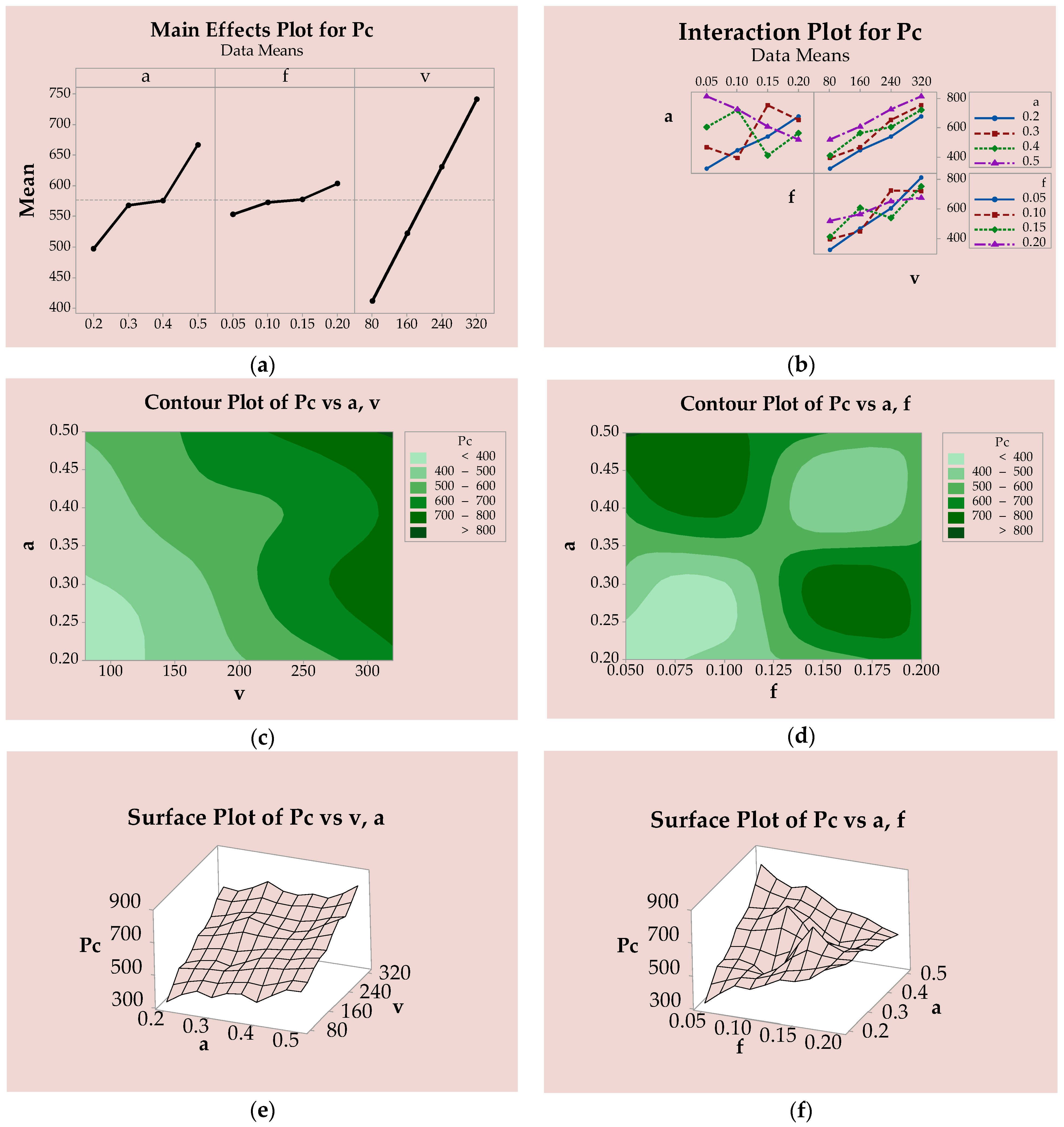
In the context of sustainable machining, minimizing power consumption during cutting is essential. Cutting parameters and the cooling environment have a strong influence on energy utilization. Therefore, this study measures power consumption under different combinations of input terms, and the measured power consumption values are reported in Table 2. The highest power consumption (813.25 W) during cutting was notice under the highest speed (320 m/min), lowest feed (0.05 mm/rev), and highest depth of cut. Similarly, the minimum power consumption (323.41 W) corresponds to the lowest level of cutting variables (run 1). Angappan et al. [62] reported a minimal power consumption of 6082 W while turning Incoloy 800H at a speed of 35 m/min, a feed of 0.02 mm/rev, and a depth of cut of 0.5 mm. However, the current study demonstrates significant energy saving in turning Incoloy 800H alloy under twin-nozzle MQL using groundnut oil. The power consumption was augmented linearly with speed, while it was also increasing with increased feed rate and depth of cut, as shown in Figure 9a. Similar outcomes were reported by Nur et al. [63] during the machining of nickel base alloys. According to Muthuswamy [64], higher cutting speeds removed more material in less time, which in turn enhanced power consumption during machining. Moreover, in theory, power consumption is directly proportional to cutting speed, resulting in a linear increase in power usage as the cutting speed rises [64]. The interaction effect of the feed–depth of cut pair was found to be relevant irrespective of other parameter combinations, as indicated by the non-parallel curves (Figure 9b). From the contour plots (Figure 9c), the green shades are becoming deeper with increasing depth of cut and cutting speed, indicating higher power consumption with simultaneous increases in both parameters. Additionally, the power consumption in machining increased substantially when the cutting speed exceeded 240 m/min. From Figure 9d, the lower feed coupled with higher depth of cut produced higher power consumption due to increasing machining cutting time, while the same result was noticed when feed was higher and depth of cut was lower. Additionally, lower feed and depth of cut exhibited lower power consumptions. Similarly, higher depth of cut–feed attributed to smaller power consumption. From the surface plots (Figure 9e), a diagonal increase in power consumption was noticed together with an increase in depth of cut and feed. Also, the lowest depth of cut–speed exhibited the least power consumption while the highest depth of cut–speed provided the highest power consumption. From plot (Figure 9f), the uneven variations in power consumption were seen when feed and depth of cut changes. The lowest feed with largest depth of cut exhibited high power consumption. ANOVA (Table 5) confirmed that cutting speed had the highest impact on power consumption (78.70%), followed by depth of cut (18.78%). Aside from feed rate, other factors were statistically significant. Similar effects of cutting speed and depth of cut on power consumption were reported by Abbas et al. [65]. In contrast to these results, Nur et al. [63] reported that speed along with tool feed had a significant impression on power consumption during the machining of nickel-based alloys.
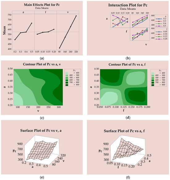
Figure 9.
Graphs showing the impact of cutting variables on Pc (a) main effects plot (b) interaction plots (c,d) contour plots (e,f) surface plots.
Table 5.
ANOVA outcomes for Pc.
3.4. Discussion of Carbon Emission
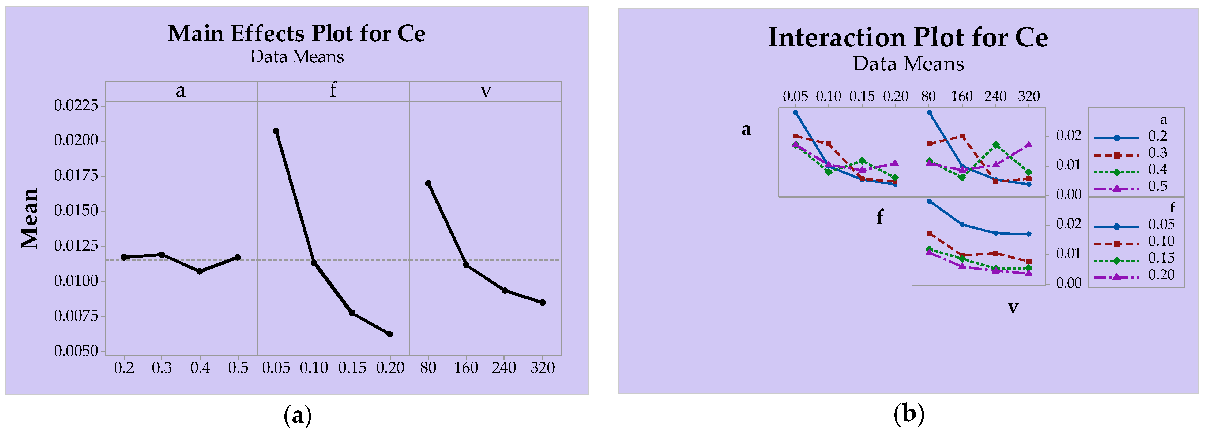
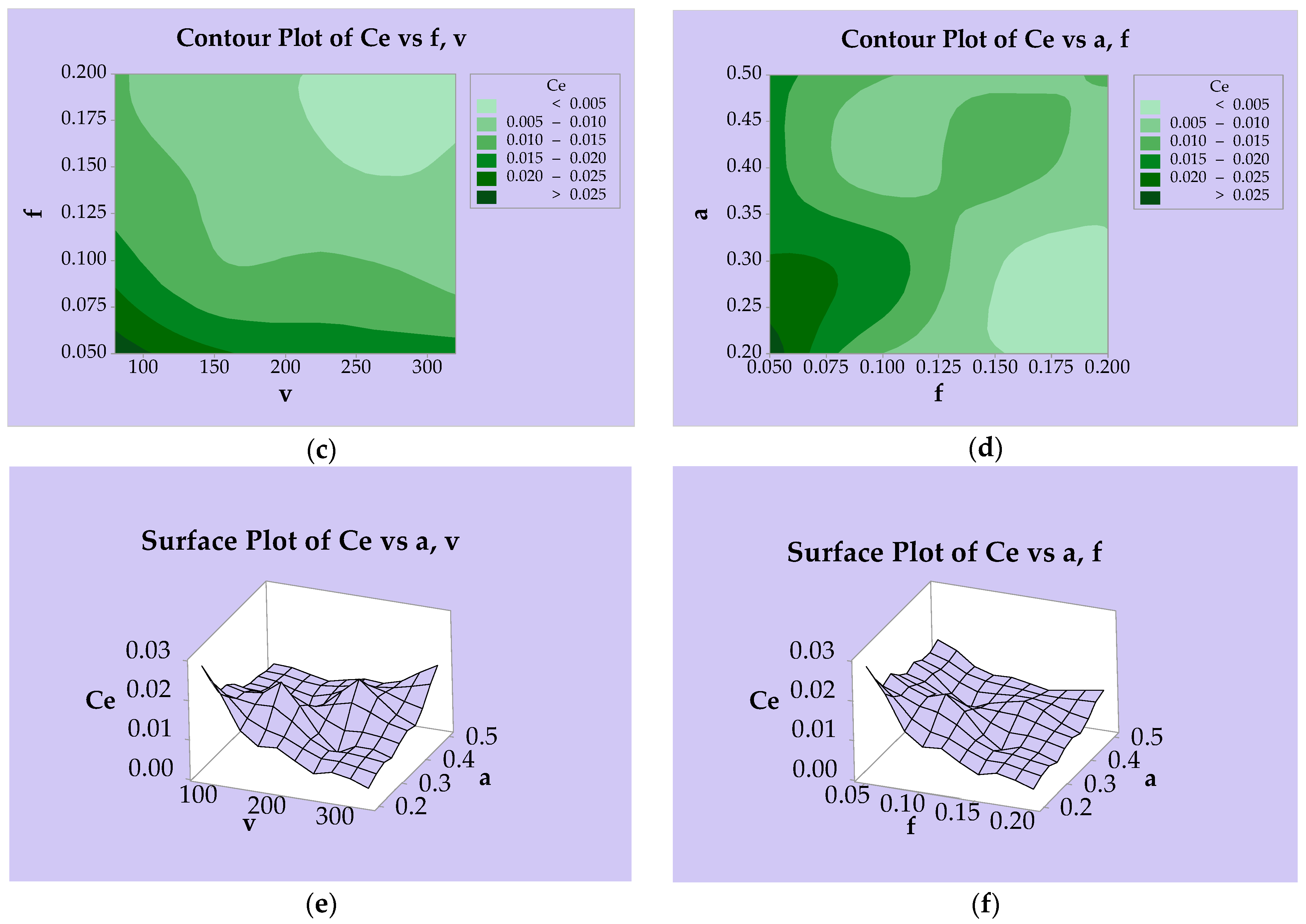
In recent years, evaluating carbon emissions in machining has become essential for both environmental and industrial purposes. It supports eco-friendly manufacturing, reduces energy use and cost, enhances machining efficiency, and ensures compliance with government regulations. Additionally, it helps determine whether a process is sustainable for industrial applications. It also helps to determine whether the process is sustainable for industrial use or not. In this research, the carbon emissions for different cutting setting are estimated and reported in Table 2. The carbon emission decreased with increasing feed rate and cutting speed, as shown in Figure 10a. Similar trends were reported by Ross et al. [66] in turning Monel alloys. However, as feed rate and speed increased, tool wear and surface roughness also improved. Therefore, optimizing the process variable is essential to balance carbon emission with enhanced productivity. The interaction effect of speed-feed was found to be effective as the curves are near-parallel, as shown in Figure 10b. From contour plots (Figure 10c), the carbon emission was reducing diagonally with simultaneously increasing speed–feed. Higher carbon emission was shown by deep green, while lighter colour denotes lower carbon emission. The carbon emission was most favourable (very light green colour) when feed and speed were higher than 0.15 mm/rev and 200 m/min, correspondingly. From other plots (Figure 10d), the most favourable carbon emission was found when the depth of cut was below 0.35 mm and feed rate exceeded 0.15 mm/rev. From surface plots (Figure 10e), the highest carbon emission was found with the lowest speed and depth of cut. Liu et al. [67] found minimal carbon emissions at low feed rate and high cutting speed. The carbon emission was growing slowly with increasing depth of cut. At the highest depth of cut and maximum cutting speed, carbon emissions increased slightly because removing thicker material required more energy. The lowest carbon emissions occurred at high cutting speed combined with a shallow depth of cut. Figure 10f shows a decrease in carbon emissions as both feed and depth of cut increased. The highest emissions were observed at low feed and shallow depth. Conversely, the lowest emissions were recorded at high feed and low depth. ANOVA (Table 6) showed the highest F-value for feed, followed by cutting speed, indicating that feed had the greatest impact (72.57%) on carbon emission, followed by speed (25.28%). Moreover, the p-values for both feed and speed were zero (≤0.05), indicating that both factors were statistically significant, while depth of cut was said to be insignificant due to its higher p-value (>0.05). In contrast to these findings, Liu et al. [67] found that the cutting speed had the highest impact on carbon emissions.

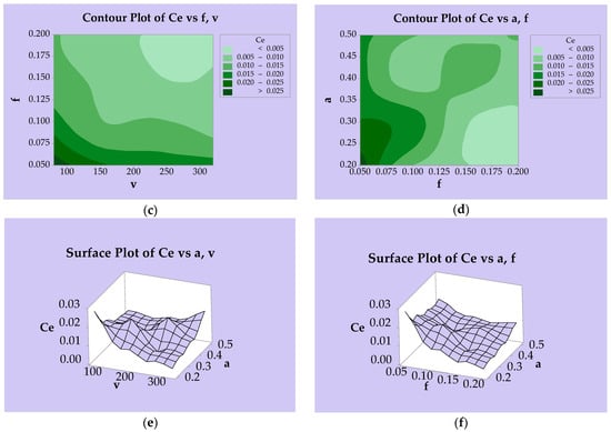
Figure 10.
Graphs showing the impact of cutting variables on Ce (a) main effects plot (b) interaction plots (c,d) contour plots (e,f) surface plots.
Table 6.
ANOVA outcomes for Ce.
3.5. Discussion of Chip Morphology
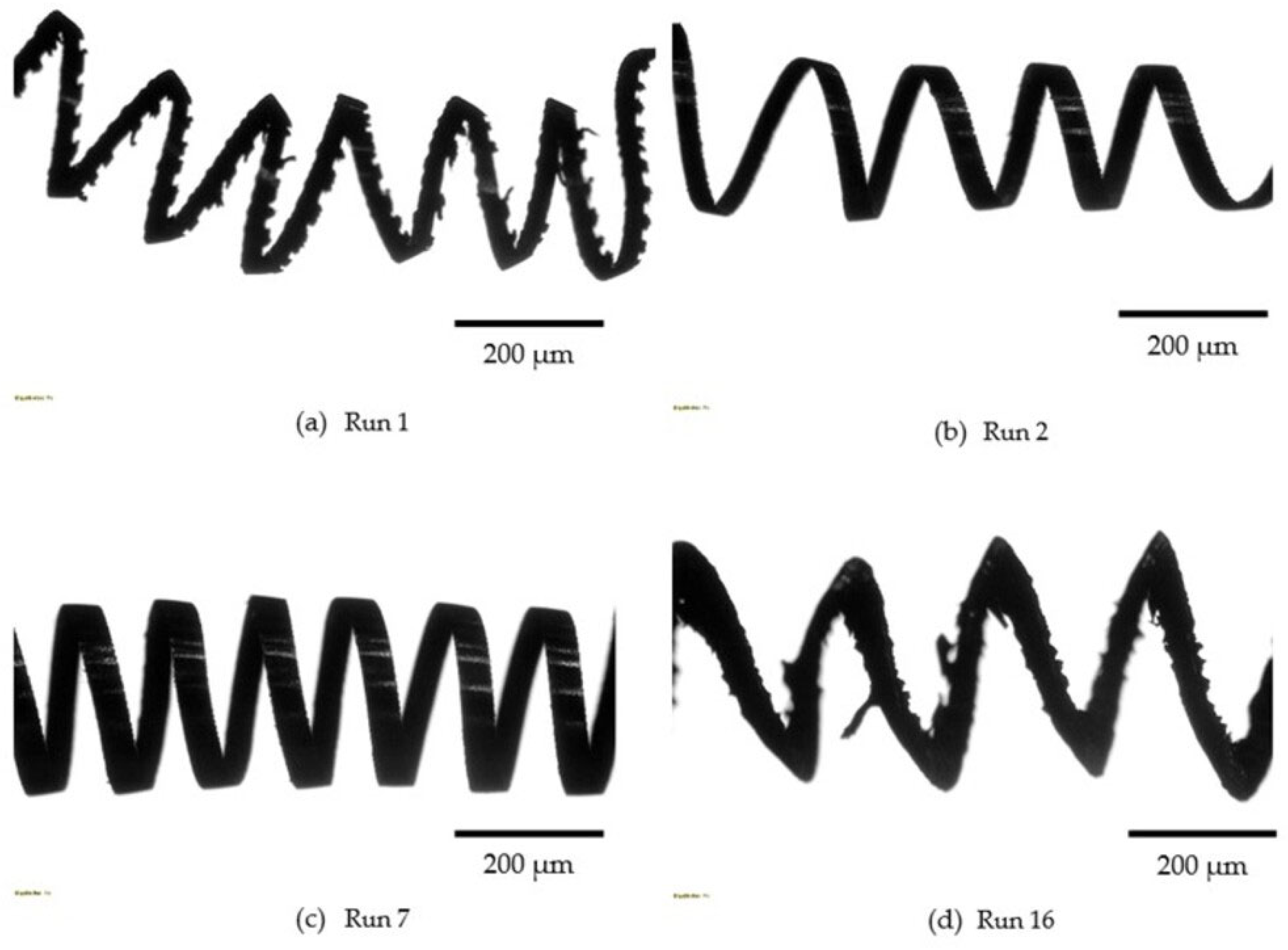
Chip morphology reflects the machinability behaviour of a material under specific cutting conditions. In this study, chips exhibited a continuous helical shape with varying curl radii, as illustrated in Figure 11. At a lower speed of 80 m/min, the saw tooth pattern (non-uniform shape) was observed along the chip edges, attributed to fluctuations in cutting force at this speed (Figure 11a,d). Conversely, at higher cutting speeds exceeding 160 m/min), a uniform tooth pattern appeared at the chip edges (Figure 11b,c). The curl radius of chips increased with the feed rate [68]. Additionally, chip thickness increased with greater depth of cut and feed rate due to enlarged cross-sectional area of the chip [69]. The application of pressurized mist lubricant during machining facilitated efficient chip evacuation from the cutting zone, thereby preventing damage to the finish surface.
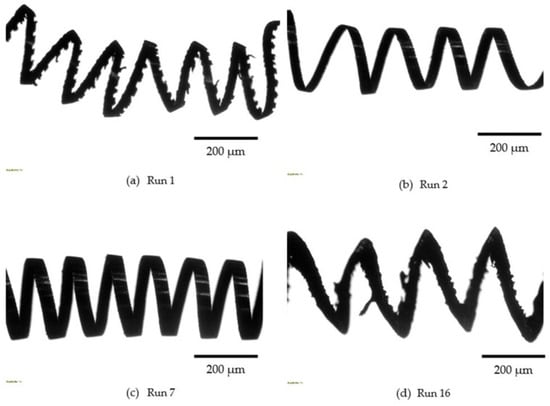
Figure 11.
Chips obtained in different runs.
Further, SEM and EDS analyses were performed on the chips collected during Run 1 and Run 4. In both runs (Figure 12 and Figure 13), burr formation on the chip edges was observed. At lower speeds, only fine serration formed, whereas at higher cutting speeds, both primary and secondary serrations were apparent, as shown in Figure 12 and Figure 13, respectively. Additionally, a uniform tooth profile developed along the chip edge at higher speeds, likely due to more consistent plastic deformation under those conditions [70]. In both runs, tool-derived elements, specifically aluminum (Al) and titanium (Ti), were detected on the chips, indicating micro-adhesion of tool coating material. Moreover, the weight % of Al and Ti increased under high-speed machining compared to low-speed conditions, suggesting greater micro-adhesion resulting from elevated cutting temperature during high speed and feed operations.
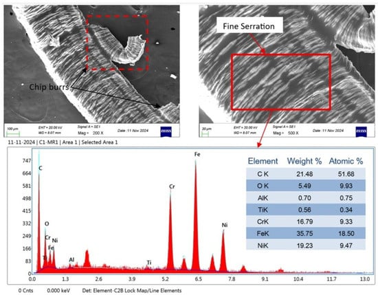
Figure 12.
SEM and EDS results for the chip obtained with the lowest values of cutting parameters (Run 1: a = 0.2 mm, f = 0.05 mm/rev, and v = 80 m/min).
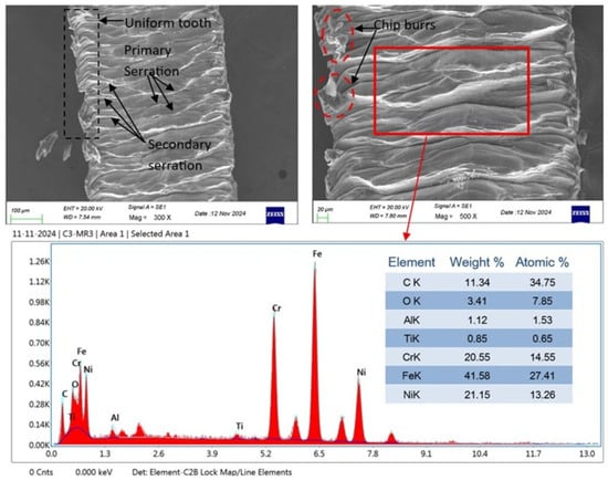
Figure 13.
SEM and EDS results for the chip obtained with the highest feed rate and cutting speed (Run 4: a = 0.2 mm, f = 0.2 mm/rev, and v = 320 m/min).
4. WASPAS Multi Objective Assessment
Multi-objective optimization based on ratio analysis (MOORA) is one of the most popular multi-criteria decision-making approaches used in many optimization problems. This technique employs dimensionless square root ratios for evaluating alternatives and was first used by Brauers and Zavadskas in transitional economy problems [71]. The MOORA follows specific series of stages in its application for ranking the available alternatives [71,72]:
Stage 1: In the first stage, the problem and objectives are fixed. The alternatives and criteria are identified. There are 16 combinations of speed, feed, and depth of cut which make 16 alternatives. The criteria taken are surface roughness (Ra), flank wear (VBc), power consumption (Pc), and carbon emission (Ce), totaling four criteria. All the chosen criteria are non-beneficial.
Stage 2: At this stage, a decision matrix () is created from the final response data by taking the sixteen alternatives (m) in a row and the four criteria (n) in a column. Taking response data from Table 2, a decision matrix is developed in the form of Equation (1).
Stage 3: At this stage, the decision matrix is normalized using vector normalization, so that the performance of different alternatives under a single criterion could lay between 0 and 1. The normalized matrix () is derived using Equation (2), where m = 1, 2, …, i. The computed normalized value was shown in Table 7.
Table 7.
Computed normalized, weighted normalized, resultant, and Rank data.
Stage 4: At this stage, the entropy method was employed to determine the weight for each individual response [73]. The weight calculation step began with the computation of the normalized matrix () using Equation (3), considering non-beneficial conditions for each criterion. Next, the probability associated with individual criteria () was determined using Equation (4), where m = 1, 2, 3, …, i = 16. Later, the entropy value for individual criteria () was calculated using Equation (5). Further, degree of divergence () was derived using Equation (6) and the entropy weight () for individual criteria was obtained using Equation (7), where n = 1, 2, …, j = 4. The computed weight value for Ra, VBc, Pc, and Ce were 0.2738, 0.2780, 0.2735, and 0.2146, respectfully.
Stage 5: At this stage, weighted normalized matrix () was estimated by multiplying weight of criteria to the corresponding column of the normalized decision matrix using Equation (8). The weighted normalized value is shown in Table 7.
Stage 6: At this stage, weighted normalized performance of beneficial criteria are added column-wise. Similarly, weighted performance of non-beneficial criteria is also added column-wise and subtracted from the sum of beneficial criteria using Equation (9). The alternative with the highest resultant value gives the optimal cutting parameter.
where ‘b’ denotes the number of outputs that need to be maximized, (n − b) is the number of criteria (outputs) that need to be minimized, and ‘’ denotes the resultant value of alternative concerning all the outputs. In this case, all the outputs need to be minimized, hence, the maximized term will be zero. The estimated resultant value is shown in Table 7. Further, based on estimated resultant values, ranks were assigned, as indicated in Table 7. The highest value corresponds to Rank 1, while the lowest value corresponds to Rank 16. The condition ranked first (Run 2) is considered the optimal setting for the current research. The optimal cutting parameters are cutting speed = 160 m/min; feed rate = 0.1 mm/rev, and depth of cut = 0.2 mm. The corresponding optimal response values are Ra = 0.514 µm, VBc = 0.084 mm, Pc = 448.33 W, and Ce = 0.0099 KgCO2.
5. Conclusions
In this research, the machinability behaviour of Incoloy 800HT was studied using an advanced carbide tool with biodegradable groundnut oil lubrication. A recent cooling strategy, namely twin-nozzle MQL system, was employed to deliver compressed air mixed with groundnut oil. Machineability factors such as surface roughness, tool wear, power consumption, carbon emission, and chip morphology were analyzed. The following major observations were made:
- Surface quality improved when using groundnut oil with twin-nozzle MQL, with Ra ranging from 0.514 to 1.984 µm. Favourable roughness (Ra < 0.7 µm) was achieved at cutting speeds ≤ 160 m/min, feed ≤ 0.1 mm/rev, and a depth of cut ≤ 0.3 mm. Feed rate had the strongest influence on surface finish.
- Tool flank wear progressed slowly due to effective cooling and lubrication from the twin-nozzle MQL system using groundnut oil. Wear ranged from 0.05 to 0.151 mm, with abrasion and adhesion as the main mechanisms. Cutting speed was the most influencing factor.
- Power consumption increased with cutting speed, feed rate, and depth of cut, with cutting speed having the greatest influence. The highest power (813.25 W) was recorded at maximum speed, while the lowest (321.41 W) occurred at the minimum levels of all parameters.
- Carbon emission, being a time-dependent factor, was higher at low speed and feed. It decreased with increasing feed and speed, with feed being the most influencing factor, while depth of cut had a marginal effect.
- Continuous helical chips with increasing curl radius and thickness were produced at higher feed rates and depths of cut.
- The entropy–MOORA approach identified the optimal cutting parameters as follows: cutting speed = 160 m/min; feed = 0.1 mm/rev, and depth of cut = 0.2 mm. The corresponding optimal response values were surface roughness = 0.514 µm, flank wear = 0.084 mm, power consumption = 448.33 W, and carbon emission = 0.0099 KgCO2.
Overall, groundnut oil combined with a twin-nozzle MQL demonstrated enhanced cooling and lubrication performance during machining of Incoloy 800HT alloy. Feed rate was the dominating factor which affected surface roughness and carbon emission, while cutting speed was the man parameter affecting tool flank wear and power consumption. Additionally, the employed cooling strategy presents a sustainable alternative to mineral oils and other hazardous coolants for machining hard-to-cut metallic alloys. In future studies, MQL parameters such as nozzle diameter, air pressure, nozzle distance, and nozzle orientation can be investigated. Moreover, the residual stress assessment can be included in subsequent research. It is also recommended to explore machinability performance at lower depths of cut (less than 0.2 mm).
Author Contributions
Abstract, R.R.P. and A.K.S.; Introduction, R.K. and A.P.; Methodology, R.R.P., R.K., and A.K.S.; Experimentation, R.R.P. and R.K.; Results and Discussion, R.K., R.R.P. and A.K.S.; Writing—review and editing, A.P. and A.K.S.; Supervision, A.P. and R.K.; Optimization, R.K. All authors have read and agreed to the published version of the manuscript.
Funding
This study received no financial support. The APC was covered using reviewer vouchers available to the authors.
Data Availability Statement
The raw data supporting the conclusions of this article will be made available by the authors on request.
Acknowledgments
The authors gratefully acknowledge the School of Mechanical Engineering and Central Research Facility (CRF) at Kalinga Institute of Industrial Technology (KIIT), Deemed to be University for providing necessary research facilities.
Conflicts of Interest
Authors declared no conflicts of interest.
References
- Prasad, G.; Vijay, G.S.; Kamath, C.R. Evaluation of tool wear and surface roughness in high-speed dry turning of Incoloy 800. Cogent Eng. 2024, 11, 2376913. [Google Scholar] [CrossRef]
- Purzyńska, H.; Golański, G. Incoloy 800ht iron-based superalloy–preliminary characterization. J. Met. Mater. 2022, 74, 42–46. [Google Scholar] [CrossRef]
- ALI, S.H.; Yao, Y.; Wu, B.; Zhao, B.; Ding, W.; Jamil, M.; Khan, A.; Baig, A.; Liu, Q.; Xu, D. Recent developments in MQL machining of aeronautical materials: A comparative review. Chin. J. Aeronaut. 2025, 38, 102918. [Google Scholar] [CrossRef]
- Sharma, S.; Ladakhi, T.Y.; Pradhan, B.B.; Phipon, R. A review on MQL for the machining of titanium based alloy. AIP Conf. Proc. 2020, 2273, 050074. [Google Scholar] [CrossRef]
- Hadad, M.; Beigi, M. A novel approach to improve environmentally friendly machining processes using ultrasonic nozzle–minimum quantity lubrication system. Int. J. Adv. Manuf. Technol. 2021, 114, 741–756. [Google Scholar] [CrossRef]
- Sidabutar, R.A.; Ginting, A. System Design and Development of MQL Unit for Hard Machining Application: A Review. IOP Conf. Ser. Mater. Sci. Eng. 2020, 1003, 012060. [Google Scholar] [CrossRef]
- Sultana, N. A critical review on the progress of MQL in machining hardened steels. Adv. Mater. Process. Technol. 2022, 8, 3834–3858. [Google Scholar] [CrossRef]
- Kasim, M.S.; Hafiz, M.S.A.; Ghani, J.A.; Haron, C.H.C.; Izamshah, R.; Aziz, M.S.A.; Mohamad, W.N.F.; Wong, P.K.; Saedon, J. Chip Morphology in Ball Nose End Milling Process of Nickel-Based Alloy Material under MQL Condition. Int. J. Adv. Manuf. Technol. 2019, 103, 4621–4625. [Google Scholar] [CrossRef]
- Virdi, R.L.; Chatha, S.S.; Singh, H. Experimental investigations on the tribological and lubrication behaviour of minimum quantity lubrication technique in grinding of Inconel 718 alloy. Tribol. Int. 2021, 153, 106581. [Google Scholar] [CrossRef]
- Bhowmick, S.; Alpas, A.T. The role of diamond-like carbon coated drills on minimum quantity lubrication drilling of magnesium alloys. Surf. Coat. Technol. 2011, 205, 5302–5311. [Google Scholar] [CrossRef]
- Barik, E.S.; Jena, P.C.; Behera, R.K.; Sethy, S.; Das, S.R. Experimental Investigation and Sustainability Assessment in Turning of Newly Developed AMMC (Al–Mg–Si–Cu–SiC) Using Coated Carbide Tool Under Minimum Quantity Lubrication. Arab. J. Sci. Eng. 2025, 1–22. [Google Scholar] [CrossRef]
- Leppert, T. Surface layer properties of AISI 316L steel when turning under dry and with minimum quantity lubrication conditions. Proc. Inst. Mech. Eng. B J. Eng. Manuf. 2012, 226, 617–631. [Google Scholar] [CrossRef]
- Boswell, B.; Islam, M.N.; Davies, I.J.; Ginting, Y.R.; Ong, A.K. A review identifying the effectiveness of minimum quantity lubrication (MQL) during conventional machining. Int. J. Adv. Manuf. Technol. 2017, 92, 321–340. [Google Scholar] [CrossRef]
- Sankaranarayanan, R.A.; Rajesh Jesudoss Hynes, N.A.; Senthil Kumar, J.B.; Krolczyk, G.M. A comprehensive review on research developments of vegetable-oil based cutting fluids for sustainable machining challenges. J. Manuf. Processes 2021, 67, 286–313. [Google Scholar] [CrossRef]
- Caballero, B.; Finglas, P.; Toldra, F. Encyclopedia of Food Sciences and Nutrition, 2nd ed.; Elsevier: Amsterdam, The Netherlands, 2003; Available online: https://www.cabidigitallibrary.org (accessed on 21 July 2025).
- Singh, A.K.; Gupta, A.K. Metal working fluids from vegetable fluids. J. Synth. Lubr. 2006, 123, 167–176. [Google Scholar] [CrossRef]
- Saleem, M.Q.; Mehmood, A. Eco-friendly precision turning of superalloy Inconel 718 using MQL based vegetable oils: Tool wear and surface integrity evaluation. J. Manuf. Processes 2022, 73, 112–127. [Google Scholar] [CrossRef]
- Sarkar, S.; Datta, S. Machining performance of inconel 718 under dry, MQL, and nanofluid MQL conditions: Application of coconut oil (base fluid) and multi-walled carbon nanotubes as additives. Arab. J. Sci. Eng. 2021, 46, 2371–2395. [Google Scholar] [CrossRef]
- Ekinovic, S.; Prcanovic, H.; Begovic, E. Oil-on-water mql machining of nickel based super alloy Nimonic C263. Int. J. Adv. Res. 2017, 5, 2471–2486. [Google Scholar] [CrossRef] [PubMed]
- Tazehkandi, A.H.; Shabgard, M.; Pilehvarian, F. On the feasibility of a reduction in cutting fluid consumption via spray of biodegradable vegetable oil with compressed air in machining Inconel 706. J. Clean. Prod. 2015, 104, 422–435. [Google Scholar] [CrossRef]
- Tazehkandi, A.H.; Shabgard, M.; Pilehvarian, F. Application of liquid nitrogen and spray mode biodegradable vegetable cutting fluid with compressed air in order to reduce cutting fluid consumption in turning Inconel 740. J. Clean. Prod. 2015, 108, 90–103. [Google Scholar] [CrossRef]
- Zhang, S.; Li, J.F.; Wang, Y.W. Tool life and cutting forces in end milling Inconel 718 under dry and minimum quantity cooling lubrication cutting conditions. J. Clean. Prod. 2012, 32, 81–87. [Google Scholar] [CrossRef]
- Tamang, S.K.; Chandrasekaran, M.; Sahoo, A.K. Sustainable machining: An experimental investigation and optimization of machining Inconel 825 with dry and MQL approach. J. Braz. Soc. Mech. Sci. Eng. 2018, 40, 374. [Google Scholar] [CrossRef]
- Gupta, M.K.; Boy, M.; Korkmaz, M.E.; Yasar, N.; Günay, M.; Krolczyk, G.M. Measurement and analysis of machining induced tribological characteristics in dual jet minimum quantity lubrication assisted turning of duplex stainless steel. Measurement 2022, 187, 110353. [Google Scholar] [CrossRef]
- Sohrabpoor, H.; Khanghah, S.P.; Teimouri, R. Investigation of lubricant condition and machining parameters while turning of AISI 4340. Int. J. Adv. Manuf. Technol. 2015, 76, 2099–2116. [Google Scholar] [CrossRef]
- Mia, M.; Dhar, N.R. Effects of duplex jets high-pressure coolant on machining temperature and machinability of Ti-6Al-4V superalloy. J. Mater. Process Technol. 2018, 252, 688–696. [Google Scholar] [CrossRef]
- Mia, M.; Dhar, N.R. Influence of single and dual cryogenic jets on machinability characteristics in turning of Ti-6Al-4V. Proc. Inst. Mech. Eng. Part B J. Eng. Manuf. 2019, 233, 711–726. [Google Scholar] [CrossRef]
- Thamizhmanii, S.; Rosli, S.H. A study of minimum quantity lubrication on Inconel 718 steel. Arch. Mater. Sci. Eng. 2009, 39, 38–44. Available online: www.archivesmse.org (accessed on 16 June 2025).
- Cai, L.; Feng, Y.; Liang, S.Y. Analytical Modelling of Cutting Force in End-Milling with Minimum Quantity Lubrication. Int. J. Precis. Eng. Manuf. 2024, 25, 899–912. [Google Scholar] [CrossRef]
- Cai, L.; Feng, Y.; Lu, Y.-T.; Lin, Y.-F.; Hung, T.-P.; Hsu, F.-C.; Liang, S.Y. Analytical Model for Temperature Prediction in Milling AISI D2 with Minimum Quantity Lubrication. Metals 2022, 12, 697. [Google Scholar] [CrossRef]
- Yıldırım, Ç.V.; Kıvak, T.; Sarıkaya, M.; Şirin, Ş. Evaluation of tool wear, surface roughness/topography and chip morphology when machining of Ni-based alloy 625 under MQL, cryogenic cooling and CryoMQL. J. Mater. Res. Technol. 2020, 9, 2079–2092. [Google Scholar] [CrossRef]
- Kamata, Y.; Obikawa, T. High speed MQL finish-turning of Inconel 718 with different coated tools. J. Mater. Res. Technol. 2007, 192–193, 281–286. [Google Scholar] [CrossRef]
- Polvorosa, R.; Suárez, A.; de Lacalle, L.L.; Cerrillo, I.; Wretland, A.; Veiga, F. Tool wear on nickel alloys with different coolant pressures: Comparison of Alloy 718 and Waspaloy. J. Manuf. Processes 2017, 26, 44–56. [Google Scholar] [CrossRef]
- Jindal, P.C.; Santhanam, A.T.; Schleinkofer Shuster, A.F. Performance of PVD TiN, TiCN and TiAlN coated cemented carbide tools in turning. Int. J. Refract. Met. Hard Mater. 1999, 17, 163–170. [Google Scholar] [CrossRef]
- Prengel, H.G.; Jindal, P.C.; Wendt, K.H.; Santhanam, A.T.; Hedge, P.L.; Penich, R.M. A new class of high performance PVD coating for carbide cutting tools. Surf. Coat. Technol. 2001, 139, 25–34. [Google Scholar] [CrossRef]
- Bhatt, A.; Attia, H.; Vargas, R.; Thomson, V. Wear mechanisms of WC coated and uncoated tools in finish turning of Inconel 718. Tribol. Int. 2010, 43, 1113–1121. [Google Scholar] [CrossRef]
- Palanisamy, A.; Jeyaprakash, N.; Sivabharathi, V.; Sivasankaran, S. Effects of dry turning parameters of Incoloy 800H superalloy using Taguchi-based Grey relational analysis and modeling by response surface methodology. Proc. Inst. Mech. Eng. Part C J. Mech. Eng. Sci. 2022, 236, 607–623. [Google Scholar] [CrossRef]
- Frifita, W.; Ben Salem, S.; Haddad, A.; Yallese, M.A. Optimization of machining parameters in turning of Inconel 718 nickel-base super alloy. Mech. Ind. 2020, 21, 203. [Google Scholar] [CrossRef]
- Panigrahi, R.R.; Panda, A.; Sahoo, A.K.; Kumar, R.; Mishra, R.R. Turning performance analysis and optimization of processing parameters using GRA-PSO approach in sustainable manufacturing. Proc. Inst. Mech. Eng. Part E J. Process Mech. Eng. 2022, 236, 2404–2419. [Google Scholar] [CrossRef]
- Jovicic, G.; Milosevic, A.; Kanovic, Z.; Sokac, M.; Simunovic, G.; Savkovic, B.; Vukelic, D. Optimization of dry turning of Inconel 601 alloy based on surface roughness, tool wear, and material removal rate. Metals 2023, 13, 1068. [Google Scholar] [CrossRef]
- Bhandarkar, L.; Mohanty, P.; Sarangi, S. Experimental study and multi-objective optimization of process parameters during turning of 100Cr6 using C-type advanced coated tools. Proc. Inst. Mech. Eng. Part C J. Mech. Eng. Sci. 2021, 235, 7634–7654. [Google Scholar] [CrossRef]
- Kumar, R.; Sahoo, A.K. Pulsating minimum quantity lubrication assisted high speed turning on bio-medical Ti-6Al-4V ELI Alloy: An experimental investigation. Mech. Ind. 2020, 21, 625. [Google Scholar] [CrossRef]
- Mallick, R.; Kumar, R.; Panda, A.; Sahoo, A.K.; Das, D. Synthesis of an Ionic Liquid-Based Cutting Lubricant and Its Performance Comparison with Mineral Oil in Hard Turning. Lubricants 2025, 13, 166. [Google Scholar] [CrossRef]
- Yan, L.; Yuan, S.; Liu, Q. Influence of minimum quantity lubrication parameters on tool wear and surface roughness in milling of forged steel. Chin. J. Mech. Eng. 2012, 25, 419–429. [Google Scholar] [CrossRef]
- Kumar, A.; Singh, G.; Aggarwal, V. Analysis and optimization of nozzle distance during turning of EN 31 steel using minimum quantity lubrication. Mater. Today Proc. 2022, 49, 1360–1366. [Google Scholar] [CrossRef]
- Khatai, S.; Kumar, R.; Panda, A.; Sahoo, A.K. WASPAS Based Multi Response Optimization in Hard Turning of AISI 52100 Steel under ZnO Nanofluid Assisted Dual Nozzle Pulse-MQL Environment. Appl. Sci. 2023, 13, 10062. [Google Scholar] [CrossRef]
- Mallick, R.; Kumar, R.; Panda, A.; Sahoo, A.K. Hard Turning Performance Investigation of AISI D2 Steel under a Dual Nozzle MQL Environment. Lubricants 2023, 11, 16. [Google Scholar] [CrossRef]
- Hossain, S.; Abedin, M.Z.; Saha, R.K.; Touhiduzzaman, M.D.; Jakir Hossen, M.D. Optimization of cutting temperature and surface roughness in CNC turning of Ti-6Al-4V alloy using response surface methodology. Heliyon 2025, 11, e41051. [Google Scholar] [CrossRef] [PubMed]
- Khatai, S.; Sahoo, A.K.; Kumar, R.; Panda, A. Sustainable hard machining under zirconia nano-cutting fluid: A step towards a green and cleaner manufacturing process. Measurement 2025, 242, 116087. [Google Scholar] [CrossRef]
- Cui, Z.; Ni, J.; He, L.; Su, R.; Wu, C.; Xue, F.; Sun, J. Assessment of cutting performance and surface quality on turning pure polytetrafluoroethylene. J. Mater. Res. Technol. 2022, 20, 2990–2998. [Google Scholar] [CrossRef]
- Song, X.; He, W.; Ihara, T. A Novel Approach for Dry Cutting Inconel 718 in a More Sustainable and Low-Cost Way by Actively and Purposely Utilizing the Built-Up Layer. Micromachines 2023, 14, 1787. [Google Scholar] [CrossRef] [PubMed]
- Palanisamy, A.; Selvaraj, T. Optimization of machining parameters for dry turning of Incoloy 800H using Taguchi-based grey relational analysis. Mater. Today Proc. 2018, 5, 7708–7715. [Google Scholar] [CrossRef]
- Palanisamy, A.; Selvaraj, T.; Sivasankaran, S. Optimization of Turning Parameters of Machining Incoloy 800H Superalloy Using Cryogenically Treated Multilayer CVD-Coated Tool. Arab. J. Sci. Eng. 2018, 43, 4977–4990. [Google Scholar] [CrossRef]
- Zhu, S.; Huang, P. Influence mechanism of morphological parameters on tribological behaviors based on bearing ratio curve. Tribol. Int. 2017, 109, 10–18. [Google Scholar] [CrossRef]
- Anurag; Kumar, R.; Sahoo, A.K.; Panda, A. Comparative performance analysis of coated carbide insert in turning of Ti-6Al-4V ELI grade alloy under dry, minimum quantity lubrication and spray impingement cooling environments. J. Mater. Eng. Perform. 2022, 31, 709–732. [Google Scholar] [CrossRef]
- Sahoo, S.P.; Datta, S. Dry MQL, and Nanofluid MQL Machining of Ti–6Al–4V Using Uncoated WC–Co Insert: Application of Jatropha Oil as Base Cutting Fluid and Graphene Nanoplatelets as Additives. Arab. J. Sci. Eng. 2020, 45, 9599–9618. [Google Scholar] [CrossRef]
- Zheng, G.; Xu, R.; Cheng, X.; Zhao, G.; Li, L.; Zhao, J. Effect of cutting parameters on wear behavior of coated tool and surface roughness in high-speed turning of 300M. Measurement 2018, 125, 99–108. [Google Scholar] [CrossRef]
- Beake, B.D.; Endrino, J.L.; Kimpton, C.; Fox-Rabinovich, G.S.; Veldhuis, S.C. Elevated temperature repetitive micro-scratch testing of AlCrN, TiAlN and AlTiN PVD coatings. Int. J. Refract. Met. Hard Mater. 2017, 69, 215–226. [Google Scholar] [CrossRef]
- Veerappan, G.; Pritima, D.; Parthsarathy, N.R.; Ramesh, B.; Jayasathyakawin, S. Experimental investigation on machining behavior in dry turning of nickel based super alloy-Inconel 600 and analysis of surface integrity and tool wear in dry machining. Mater. Today Proc. 2022, 59, 1566–1570. [Google Scholar] [CrossRef]
- Bilga, P.S.; Singh, S.; Kumar, R. Optimization of energy consumption response parameters for turning operation using taguchi method. J. Clean. Prod. 2016, 137, 1406–1417. [Google Scholar] [CrossRef]
- Dash, L.; Padhan, S.; Das, A. Machinability investigation and sustainability assessment in hard turning of AISI D3 steel with coated carbide tool under nanofluid minimum quantity lubrication-cooling condition. Proc. Inst. Mech. Eng. Part C J. Mech. Eng. Sci. 2021, 235, 6496–6528. [Google Scholar] [CrossRef]
- Angappan, P.; Thangiah, S.; Subbarayan, S. Taguchi-based grey relational analysis for modeling and optimizing machining parameters through dry turning of Incoloy 800H. J. Mech. Sci. Technol. 2017, 31, 4159–4165. [Google Scholar] [CrossRef]
- Nur, R.; Noordin, M.Y.; Izman, S. The effect of cutting parameters on power consumption during turning nickel based alloy. Adv. Mater. Res. 2013, 845, 799–802. [Google Scholar] [CrossRef]
- Muthuswamy, P. Comparison of machining forces, power consumption, and specific cutting energy in tools with grooved cutting edges for sustainable manufacturing. Adv. Mater. Process Technol. 2024, 1–15. [Google Scholar] [CrossRef]
- Abbas, A.T.; Anwar, S.; Abdelnasser, E.; Luqman, M.; Qudeiri, J.E.A.; Elkaseer, A. Effect of Different Cooling Strategies on Surface Quality and Power Consumption in Finishing End Milling of Stainless Steel 316. Materials 2021, 14, 903. [Google Scholar] [CrossRef] [PubMed]
- Ross, N.S.; Rai, R.; Ananth, M.B.J.; Srinivasan, D.; Ganesh, M.; Gupta, M.K.; Korkmaz, M.E.; Królczyk, G.M. Carbon emissions and overall sustainability assessment in eco-friendly machining of Monel-400 alloy. Sustain. Mater. Technol. 2023, 37, e00675. [Google Scholar] [CrossRef]
- Liu, Z.J.; Sun, D.P.; Lin, C.X.; Zhao, X.Q.; Yang, Y. Multi-objective optimization of the operating conditions in a cutting process based on low carbon emission costs. J. Clean. Prod. 2016, 124, 266–275. [Google Scholar] [CrossRef]
- Jiang, H.; Ren, Z.; He, L.; Yuan, S.; Zou, Z. Forming process and evaluation of chip in machining of high-strength steel by an independent-developed microgroove turning tool. Sci. Prog. 2021, 104, 1–18. [Google Scholar] [CrossRef] [PubMed]
- Hamadi, B.; Chaour, M.; Cherrad, M.L.; Boucherma, D.; Achour, T.; Yallese, M.A. Chip formation analysis during dry turning of C45 steel. Stud. Eng. Exact. Sci. 2024, 5, 1–15. [Google Scholar] [CrossRef]
- Cui, X.; Zhao, B.; Jiao, F.; Zheng, J. Chip formation and its effects on cutting force, tool temperature, tool stress, and cutting edge wear in high- and ultra-high-speed milling. Int. J. Adv. Manuf. Technol. 2016, 83, 55–65. [Google Scholar] [CrossRef]
- Brauers, W.K.M.; Zavadskas, E.K. The MOORA method and its application to privatization in a transition economy. Control Cybern. 2006, 35, 445–469. [Google Scholar]
- Liang, Z.; Yun, T.J.; WB, O.H.; BR, L.; IS, K. A study on MOORA-based Taguchi method for optimization in automated GMA welding process. Mater. Today Proc. 2020, 22, 1778–1785. [Google Scholar] [CrossRef]
- Kumar, R.; Singh, S.; Bilga, P.S.; Kumar, R.; Jatin Singh, J.; Singh, S.; Scutaru, M.L.; Pruncu, C.I. Revealing the benefits of entropy weights method for multi-objective optimization in machining operations: A critical review. J. Mater. Res. Technol. 2021, 10, 1471–1492. [Google Scholar] [CrossRef]


Disclaimer/Publisher’s Note: The statements, opinions and data contained in all publications are solely those of the individual author(s) and contributor(s) and not of MDPI and/or the editor(s). MDPI and/or the editor(s) disclaim responsibility for any injury to people or property resulting from any ideas, methods, instructions or products referred to in the content. |
© 2025 by the authors. Licensee MDPI, Basel, Switzerland. This article is an open access article distributed under the terms and conditions of the Creative Commons Attribution (CC BY) license (https://creativecommons.org/licenses/by/4.0/).