Article

Maskless Electrochemical Texturing (MECT) Applied to Skin-Pass Cold Rolling

by
Paulo L. Monteiro, Jr.
1,
Wilian Labiapari
2,
Washington M. Da Silva, Jr.
1,
Cristiano de Azevedo Celente
3 and
Henara Lillian Costa
1,3,*
1
Department of Mechanical Engineering, Universidade Federal de Uberlândia, Uberlândia 38400-901, MG, Brazil
2
Aperam South America Brazil, Timóteo 35180-018, MG, Brazil
3
School of Engineering, Universidade Federal do Rio Grande, Rio Grande 96203-900, RS, Brazil
*
Author to whom correspondence should be addressed.
Lubricants 2025, 13(7), 312; https://doi.org/10.3390/lubricants13070312
Submission received: 9 June 2025 / Revised: 10 July 2025 / Accepted: 15 July 2025 / Published: 18 July 2025

Abstract

The surface topography of the rolls used in skin-pass cold rolling determines the surface finish of rolled sheets. In this sense, work rolls can be intentionally textured to produce certain topographical features on the final sheet surface. The maskless electrochemical texturing method (MECT) is a potential candidate for industrial-scale application due to its reduced texturing cost and time when compared to traditional texturing methods. However, there are few studies in the literature that address the MECT method applied to the topography control of cold rolling work rolls. The present work aims to analyze the viability of surface texturing via MECT of work rolls used in skin-pass cold rolling. In this study, we first investigated how texturing occurs for tool steel using flat textured samples to facilitate the understanding of the dissolution mechanisms involved. In this case, a specially designed texturing chamber was built to texture flat samples extracted from an actual work roll. The results indicated that the anodic dissolution involved in tool steel texturing occurs preferentially in the metallic matrix around the primary carbides. Then, we textured a work roll used in pilot-scale rolling tests, which required the development of a special prototype to texture cylindrical surfaces. After texturing, the texture transfer from the work roll to the sheets was investigated. Rolling tests showed that the work roll surface textured with a dimple pattern generated a pillar-shaped texture pattern on the sheet surface, possibly due to a reverse extrusion mechanism.

1. Introduction

The skin-pass cold rolling process involves a slight thickness reduction of approximately 1% [1]. This process plays a crucial role in determining the surface characteristics of steel sheets, particularly for automotive applications. Furthermore, one key aspect is the ability to control the surface topography through the use of textured work rolls during the final rolling pass [2,3]. This approach enhances sheet performance by influencing properties such as lubricant retention, wear resistance, paint adhesion, and formability [4,5].
Various texturing techniques have been developed to impart specific surface characteristics to work rolls, thereby controlling the final texture of the steel sheets. Among the most commonly used methods are the topocrom method (TM) [6], shot blasting texturing (SBT) [7], electrical discharge texturing (EDT), electron beam texturing (EBT) [8], and laser beam texturing (LBT) [9,10]. Each of these techniques presents distinct advantages and limitations, influencing factors such as cost, precision, and reproducibility [2].
The topocrom method (TM) involves electrodeposition of hard chrome in the form of randomly distributed hemispherical protrusions on the work roll surface, generating a stochastic texture [11]. Shot blasting texturing (SBT) is a mechanical process where metal particles are projected onto the work roll surface, creating a rough topography [12]. Despite its cost-effectiveness, SBT is less controllable in terms of uniformity [13,14]. Electrical discharge texturing (EDT) employs electrical discharges to remove material from the surface, leading to a relatively uniform topography with controlled peak frequency [13,15,16]. Electron beam texturing (EBT) [9] and laser beam texturing (LBT) [17,18] provide high-precision deterministic textures.
One of the advantages of using deterministic rather than stochastic textures on work rolls is the improved control over lubricant entrapment inside the textures (often dimples), forming lubrication pockets [19,20,21], which enhances tribological performance in subsequent metal forming processes [22,23]. While methods such as EBT [8] and LBT [24,25] can generate deterministic textures, their high costs and operational complexity pose challenges for large-scale industrial implementation in the metal-forming industry. Consequently, alternative approaches capable of producing deterministic textures in a more cost-effective manner are of great interest.
Electrochemical machining-based techniques enable deterministic textures to be easily produced over large areas while maintaining a relatively low cost and fast processing time [26,27,28]. Maskless Electrochemical Texturing (MECT) eliminates the need for individual masking, because the mask is applied onto the cathode, enabling the texturing of many anodic pieces with a single masked cathode [29,30]. Previous studies indicate that MECT holds significant potential for industrial applications, particularly due to the use of inexpensive and relatively benign electrolytes such as NaCl solutions [31]. A limitation of this technique is the resolution of the resulting dimples, as it is challenging to achieve feature sizes below approximately 200 µm. Nonetheless, this constraint may not be a critical issue for texturing work rolls for cold rolling, since the forming process involves large contact areas.
Recent developments in MECT technology have focused on optimizing process efficiency and reducing costs. In earlier designs, the texturing chamber utilized a laser-perforated cathodic plate, directing the electrolyte flow perpendicularly through the tool onto the workpiece surface [31]. However, Dias et al. [32] proposed a modification involving a perforated polymeric adhesive mask on the cathode instead of a perforated metal tool, significantly reducing costs. Additionally, the electrolyte inlet was reoriented to flow parallel to the workpiece–tool interface, minimizing pressure drop and improving overall process stability. Nevertheless, further investigation is required to assess its applicability to the materials used in cold rolling work rolls.
Another key challenge in implementing any texturing technique for cold rolling work rolls is ensuring effective transfer of the roll texture onto the sheet surface [33]. Roll asperity penetration and reverse extrusion [34] are two primary mechanisms influencing texture transfer. The dominance of one mechanism over the other depends on factors such as rolling pressure, material properties, and the specific texturing technique used [35,36].
To date, the MECT method has not been extensively evaluated in rolling operations, particularly at an industrial or even pilot scale. Therefore, this study aims to investigate the feasibility of applying MECT as an alternative texturing method for skin-pass work rolls. Initially, flat samples of tool steel work rolls were textured using a newly designed MECT chamber and compared with texturing of AISI 1010 steel. The morphological and geometrical characteristics of the textured surfaces were analyzed, and pilot-scale rolling tests were conducted using MECT-textured work rolls and AISI 430 steel sheets.

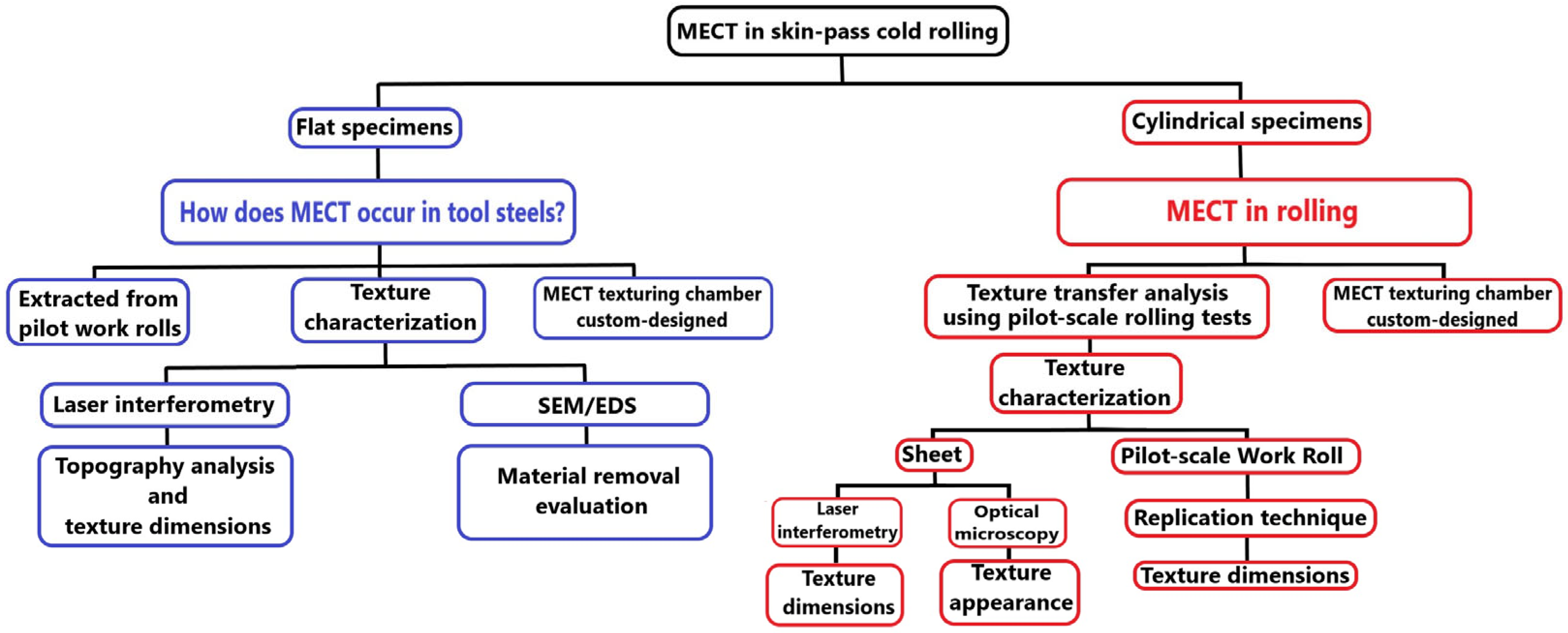
2. Experimental Procedure

Figure 1 presents an overview of the methodological approach adopted to evaluate MECT (Maskless Electrochemical Texturing) in the context of skin-pass cold rolling. The study was conducted using two types of specimens: (i) flat specimens extracted from pilot work rolls, used to understand how MECT occurs in tool steels; and (ii) cylindrical specimens (pilot-scale work rolls), employed to assess texture transfer during pilot-scale rolling tests. For flat specimens, texture characterization was performed using laser interferometry and SEM/EDS, enabling both topography analysis and material removal evaluation. For cylindrical specimens, the analysis included sheet surface characterization (texture dimensions and appearance) and replication techniques to evaluate texture dimensions on the pilot-scale work roll. Customized MECT chambers were developed and fabricated for each specimen type.

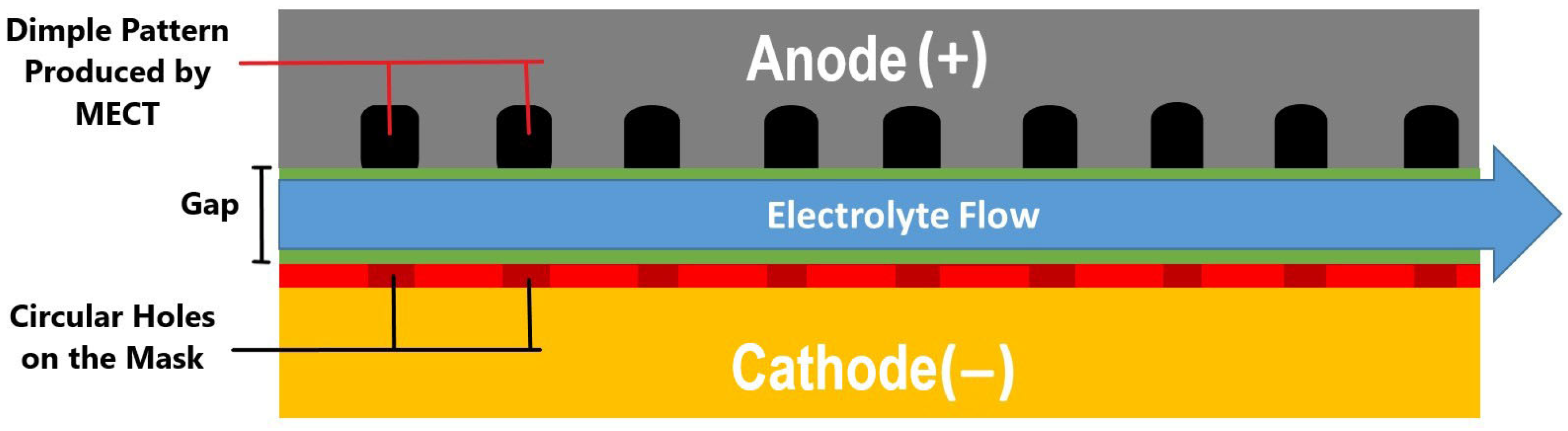
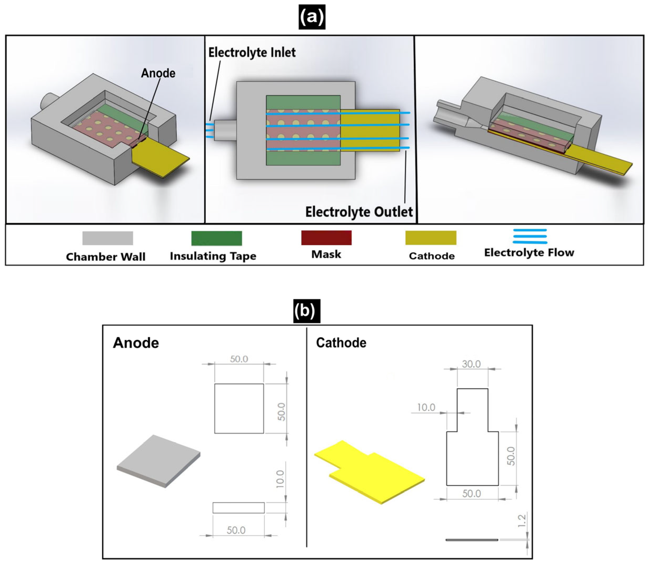
2.1. MECT Texturing of Flat Specimens

Tool steel presents complex microstructures, often consisting of carbide distributions in a metallic matrix. This may pose challenges to the use of MECT in work rolls. In order to better understand the mechanisms involved in material removal of tool steels, texturing tests were first carried out for flat samples due to their simplicity and easier gap control.
The texturing chamber for flat surfaces was designed according to the configuration proposed by Dias et al. [32]. As shown in Figure 2, the mask on the cathode leads to anodic localization, since the regions of the anode closer to the holes experience lower ohmic drop, forming dimples in the anode as the electrolyte flows parallel to the surfaces inside the gap. The use of arrays of dimples is common in the literature for applications related to the present study [5,19,37].
Figure 3 illustrates the flat surface texturing chamber developed in this work. Figure 3a (left) shows the cathode (sample) inserted into the chamber and over the tool. There is an inlet and outlet for the electrolyte (Figure 3a, center) so that it is directed parallel to the surface of the mask. The latter is an adhesive patterned mask on the surface of the metal tool. On the borders of the mask, between the workpiece and the tool, there is an insulating insert of known thickness, forming the gap for the electrolyte flow. Finally, Figure 3a (right) shows a longitudinal sectional view of the texturing chamber, where it is possible to observe the electrolyte path inside the chamber. Figure 3b shows the dimensions of the cathode and anode. It is important to notice that texturing does not occur throughout the entire surface of the workpiece (50 mm × 50 mm), as the workpiece surface regions under the insulating insert are not textured.
The chamber walls were manufactured using 3D printing. The material of the chamber walls was acrylonitrile butadiene styrene (ABS) to ensure electrical insulation and corrosion resistance. The cathode was made of AISI 430 steel and was manually sanded with sandpaper (80 to 1200 mesh). The holes in the mask (self-adhesive vinyl) were perforated by laser. An optical microscope (manufacturer Olympus, Tokyo, Japan, model BX51m) measured the holes, giving an average diameter of 722 ± 50 µm and an average distance between hole centers of 1225 ± 16 µm.
After preliminary texturing tests on flat samples extracted from a cold rolling work roll, the parameters presented in Table 1 resulted in adequate textures. Thus, this test condition was used for the surface texturing tests in this work. Each texturing test was repeated three times.
The flat surface samples were machined from a high-speed steel work roll used in a pilot rolling mill by Aperam South America. Figure 4 shows the cutting procedure using wire EDM, equipment from manufacturer Agie Charmilles, Zug, Switzerland, model FW 2U. Then, specimens were extracted with a flat face of 50 mm × 50 mm. Additionally, they were ground using a 254 mm Al2O3 abrasive wheel at 2875 RPM.
The chemical composition of the roll material was analyzed using Optical Emission Spectrometry (manufacturer Oxford Instruments, Abingdon, UK, model Foundry Master Pro). According to the standard sample preparation procedure recommended by the equipment manufacturer, a light sanding was performed with 80-mesh zirconia sandpaper. Three measurements (burns) were taken, showing consistent results and well-defined burn spots. The chemical composition of the roll material in Table 2 demonstrates that it is a high-speed steel enriched with molybdenum. The Vickers microhardness of the roll was measured as 802.75 ± 29.15 HV0.1.
In order to characterize the roll microstructure, conventional metallographic preparation consisting of plane grinding, sanding (80 to 1200 mesh), polishing (1 µm alumina paste) and etching with Nital 2% was carried out. The microstructure was analyzed using an optical microscope (manufacturer Olympus, Tokyo, Japan, model BX51m). Figure 5 shows that the microstructure consists of a metallic matrix with granular morphology, dispersed chrome precipitates, and primary molybdenum and vanadium carbides (white regions), as evidenced by EDS analysis in a previous work [1].
After texturing, the surface topography was assessed by interferometry, equipment from manufacturer Taylor Hobson, Leicester, UK, model Talysurf CLI 2000®, with a measurement rate of 500 μm/s, using continuous measurement mode with spacing of 1 μm × 10 μm. The highest density of measured points occurred in the perpendicular direction relative to the direction of obtaining surface profiles. Topographic analyses obtained by interferometry were performed using the commercial softwareMountainsLab Premium 9® developed by Digital Surf, Besançon, France. Before measuring the dimple geometry, the surface was leveled, and no waviness filter was applied. The average maximum depth corresponds to the mean value of the maximum depths measured in each dimple. Both the average maximum depth and the average dimple diameter were determined using the Particle Analysis Module in the MountainsLab Premium 9® software. Additionally, surfaces with textures were examined via scanning electron microscope (SEM) with energy dispersive spectroscopy (EDS), manufacturer Hitachi, Tokyo, Japan, model TM3000.
For comparison, AISI 1010 steel flat specimens were also textured after sanding (80 to 1200 mesh). Each texturing test was repeated three times under the same conditions described in Table 1. After the texturing tests, surface topography was analyzed using a confocal microscope, manufacturer Hyperion, Ettlingen, Germany, model OPM KF3. Morphology was also analyzed using SEM, equipment from manufacturer Oxford Instruments, Abingdon, UK, model Tescan Vega3, with ADD0048 EDS probe.

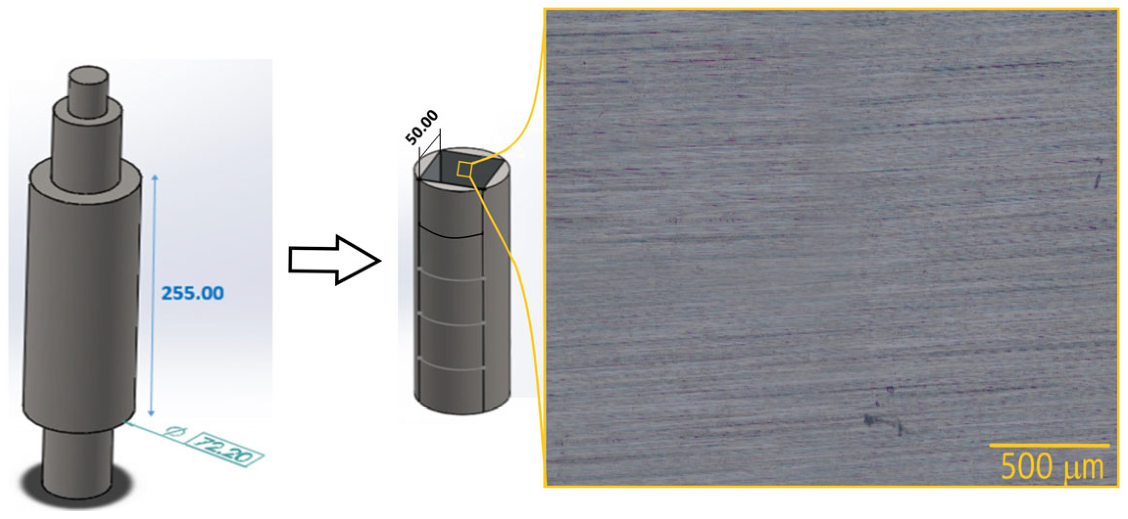
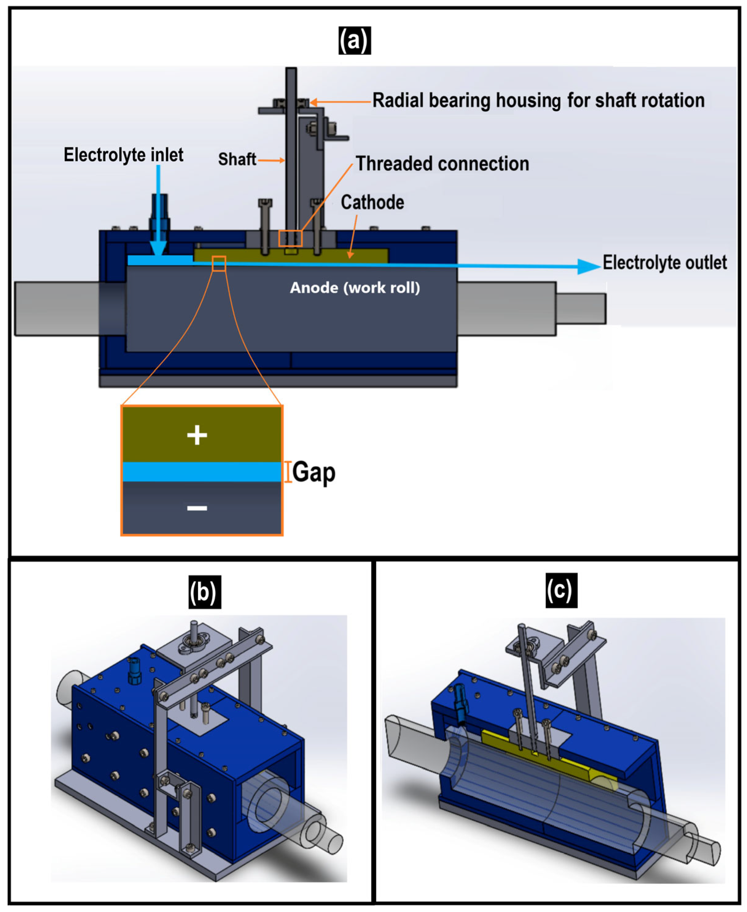
2.2. MECT Texturing of Rolls

The objective of this stage was to design and build a MECT chamber for texturing of work rolls. Further details of the developed texturing chamber can be found in a recently deposited patent mentioned at the end of the manuscript. The pilot work roll used in this study has a diameter of 72.2 mm and a length of 255 mm. To facilitate gap control, the work roll was textured in stages, each involving a textured area of 120 mm × 60 mm.
Figure 6 shows the electrochemical texturing chamber for work rolls. Figure 6a presents a sectional view, highlighting the radial bearing housing and the threaded connection for the cathode adjustment. The cathode moves only vertically, allowing precise gap control. The electrolyte enters the chamber, flows through the interelectrode gap, and exits after the texturing process. Figure 6b shows the external view of the assembled chamber. Figure 6c provides a cutaway view showing the arrangement of the cathode and the work roll, which acts as the anode.
Based on the textures obtained for the flat samples, experimental tests were conducted using the parameters presented in Table 3. Due to the size of the area to be textured, it was necessary to increase the gap to prevent excessive pressure drop in the electrolyte flow. The electrical system and electrolyte pump were the same as those employed in the texturing experiments of flat surface samples.
The textured work roll surface was analyzed using the replication technique, since its dimensions prevented direct analysis. The process used a dibenzoyl peroxide resin and a methyl methacrylate catalyst. A contact profilometer (manufacturer Hommel Etamic, Villingen-Schwenningen, Germany, model T8000) obtained surface profiles of the cured replicas, analyzed in Mountains Map Universal® version 9, to represent the textured work roll surface. The analysis followed these steps in the software: (1) shape removal with a second-degree polynomial, (2) filling of non-measured points, (3) leveling, and (4) inversion of the surface along the z-axis. Inverting the z-axis was necessary to ensure that the replicated surface matched the work roll surface in the interferometric representation. No waviness filter was applied to avoid removing relevant information from the roll topography.

2.3. Texture Transfer from Work Roll to Sheet

The analysis of the texture transfer from the work rolls to the sheets was conducted using pilot-scale cold rolling tests in a four-high rolling mill. The maximum load capacity of the rolling mill used is 150 ton. The backup rolls had diameters and lengths of 250 mm. Only one of the work rolls (shown in Figure 4) was textured. The dimensions of the textured area were 120 mm × 60 mm. The sheet material was AISI 430 stainless steel (P430F), with Vickers microhardness of 166.1 ± 5.06 HV0.1. The chemical composition is shown in Table 4. The sheet dimensions are: 25 mm (length), 100 mm (width), and 1.46 mm (thickness).
The rolling tests aimed to simulate the skin pass of cold rolling, ensuring texture transfer without significant sheet deformation. For that, dry conditions and a constant rolling speed were employed. First, preliminary tests aimed to find the ideal condition of sheet reduction for texture transfer. The results showed that with 2.1% thickness reduction, texture transfer occurred, and the sheet did not develop excessive curvature as in tests with higher reductions. Thus, rolling tests were performed with 2.1% thickness reduction, which agrees with conditions used in the literature [38]. The rolling tests for texture transfer were repeated three times. The dimple diameter and depth in the roll were selected as parameters to evaluate texture transfer.
After the rolling tests, the transferred textures on the sheets were analyzed using a confocal microscope (manufacturer Hyperion, Ettlingen, Germany, model OPM KF3) with a density of 500 points/mm, an analyzed area of 4 mm × 4 mm, a scanning rate of 1.6 mm/s, and a frequency of 800 Hz. Data analysis was performed using the Mountains Map Universal® software, version 9.0. The sheet surfaces after texture transfer were also evaluated by optical microscopy. The optical microscopy images were obtained using an optical microscope (manufacturer Olympus, Tokyo, Japan, model BX51m).

3. Results and Discussion

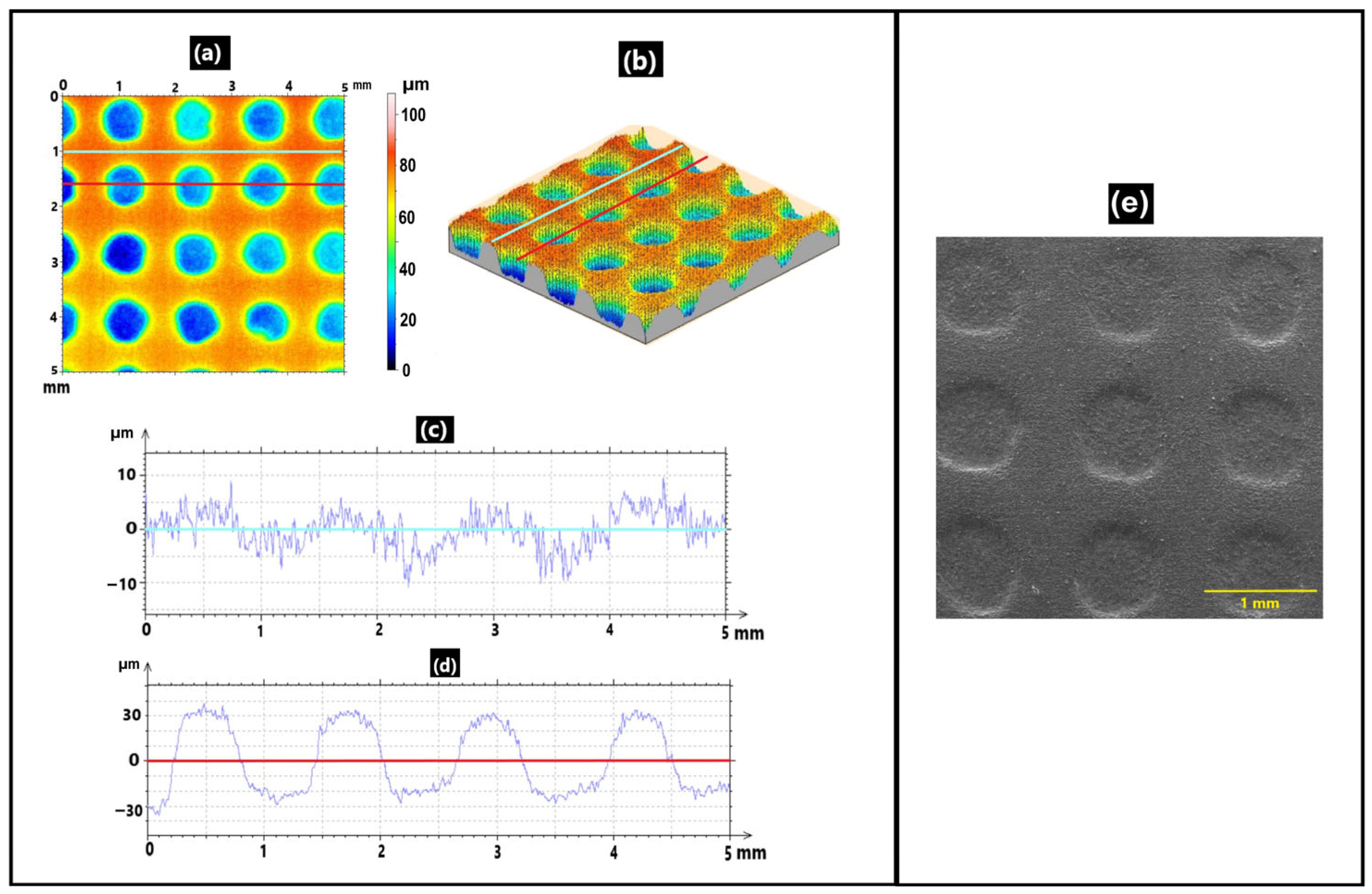
3.1. Texturing of the AISI 1010 Reference Flat Samples

Figure 7a shows the 3D topographic map of an AISI 1010 steel sample, where textures were successfully fabricated with regularly spaced dimple geometry. The lines indicate where surface profiles were extracted for analysis. Figure 7b presents a 3D view of Figure 7a. Figure 7c,d show a surface profile of a region between dimples and a surface profile intersecting a row of dimples, respectively, as indicated by the lines in Figure 7a. The profile of the region between dimples was not intact after texturing, as it appears to reproduce features of the dimple row profile. This indicates that material removal in the MECT method occurs not only in unprotected regions but also in masked areas, though to a lesser extent. This phenomenon is typical of the MECT process, as reported in the literature [31]. The average diameter was computed as 860 ± 50 µm and the average maximum depth of the textures was 34 ± 4 µm. The average dimple diameter is greater than the average hole diameter in the mask (722 ± 50 µm), indicating a slight overcut, as commonly observed in MECT [31]. Regarding the uniformity of the textures, Figure 7e shows an SEM image of a textured surface with a uniform dimple array, consistent with the mask. The successful texturing confirms that the chamber is functional for MECT on flat surfaces.
Figure 8 shows the compositional maps obtained via EDS for a region outside the dimples. The analysis was performed outside the dimples because in a tribological system, this is the area that actually comes into contact with the counterbody. In the case of rolling work rolls, these regions outside the dimples are those that make the most contact with the sheet. It can be observed that the anodic dissolution involved in the texturing process occurs uniformly in the analyzed area (Figure 8a), meaning there is no preferential material removal in any particular region. Additionally, the Fe map (Figure 8b) shows, as expected, the predominance of this element on the surface. The O map (Figure 8c) shows some areas with higher oxygen intensity that may indicate oxides. The C distribution is uniform (Figure 8d), as expected for a carbon steel sample.

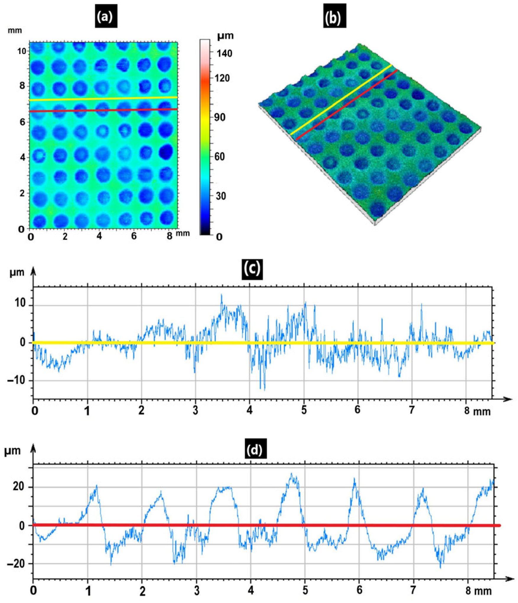
3.2. Texturing of Tool Steel Flat Samples

Figure 9a shows the surface topography of a flat sample extracted from a work roll. The texture patterns replicate the characteristics present in the mask, meaning that textures with regularly spaced dimple geometry were fabricated. It can be concluded that the surface was successfully textured. The lines indicate where surface profiles were extracted for analysis. Some dimples show a slight “bump” at the bottom, while others do not. This is probably related to non-uniform material removal, possibly due to differences in resistance to anodic dissolution of different microstructural constituents. Figure 9b shows a 3D map of Figure 9a. Figure 9c,d display surface profiles extracted from the regions indicated in Figure 9a: Figure 9c corresponds to an area between dimples, while Figure 9d intersects a row of dimples. As observed with the AISI 1010 steel samples, the profile of the region between dimples also showed roughening due to some material removal outside the dimples.
The average dimple diameter was computed as 849 ± 22 µm and the average maximum depth was 25 ± 3 µm. Similarly to the AISI 1010 steel samples, the average dimple diameter is greater than the average hole diameter in the mask (722 ± 50 µm). The average maximum depth is lower than that of the AISI 1010 steel texturing (34 ± 4 µm). This probably occurs due to the higher resistance to anodic dissolution conferred by alloying elements such as chromium and nickel. The SEM images shown in Figure 10a again show a uniform dimple array, as observed for the AISI 1010 steel samples. In Figure 10b, the inclined arrows point to marks likely caused by the electrolyte flow during the MECT process, as these marks align with the flow direction and are present both inside and outside the dimple (outlined by a semicircle in the image). The vertical arrows indicate marks aligned with the grinding process, which appear only outside the dimple, where electrochemical material removal is lower, suggesting they are residual marks from the grinding prior to texturing.
The back-scattered electron (BSE) image shown in Figure 11 combined with EDS analysis provides evidence of Cr, Fe, and C both inside and outside the dimples, consistent with the chemical composition before texturing (Table 2).
Figure 12a compares a BSE image (left) and a secondary electron (SE) image (right) inside a dimple. The outlined rectangles highlight regions of interest. The second phase observed before texturing (shown previously in Figure 5) is still present. It now appears as a raised feature (SE contrast) and is surrounded by darker regions (BSE contrast). Electrochemical removal was non-uniform, likely due to this second phase, apparently primary carbides. This behavior differs from that observed in the texturing of AISI 1010 steel samples (Figure 8).
The BSE image in Figure 12b shows another EDS analysis of a textured surface in a region outside the dimples. The EDS spectra did not reveal significant differences between the analyzed points (1, 2 and 3). According to previous results [1], the white phases (as in point 1) are believed to be Mo, V-rich carbides. These carbides are surrounded by a darker region, as shown by the EDS analysis at point 2. Anodic dissolution during texturing occurs preferentially around primary carbides, likely due to the local depletion of alloying elements (Mo, V, Cr) needed for carbide formation, making these regions more susceptible to oxidation. Additionally, the selective removal of Fe, characteristic of electrochemical texturing, may weaken the matrix, leading to carbide detachment. This is supported by the absence of the prominent Fe Kα peak (~6.4 keV) observed before texturing in Figure 12c. The contrasting dark regions likely correspond to oxidized areas due to intense electrochemical dissolution and/or regions where carbides were partially removed due to matrix weakening. Since carbides consume alloying elements from their surroundings, adjacent regions become depleted and more susceptible to oxidation.
The SEM image in Figure 13 shows a textured surface using secondary electrons (Figure 13a) and back-scattered electrons (Figure 13b). The dashed semicircles indicate the edges of the dimples. Numbered rectangles highlight regions with recurring features along the surface. Rectangle 1 shows a region outside the dimples, where the white phase (Figure 13b), seemingly protruding (Figure 13a), is over a darker region. Rectangle 2 shows a region outside the dimples containing microcavities (Figure 13a) with dark coloration (Figure 13b). Rectangle 3 shows a region inside a dimple that contains a protruding surface portion (Figure 13a), also dark-colored (Figure 13b), where intense oxidation likely occurred instead of preferential dissolution. Rectangle 4 shows a region inside a dimple that contains a cavity (Figure 13a), again with dark color (Figure 13b). Outside the dimples, where electrochemical material removal is less severe, dark regions in the form of microcavities (e.g., rectangle 2 of Figure 13a) are visible, likely where protruding carbides (white phase) existed before, as seen in rectangle 1 of Figure 13a.

3.3. Texture Transfer Results

Figure 14 presents surface topography analysis related to texture transfer. Figure 14a shows the surface topography of the replica used for analyzing the textures of the work roll before the rolling tests. The image of the replica was inverted in the z axis to reflect the true topography of the work roll. Despite the lack of texture uniformity, the replicated region shows a clear array of dimples. Figure 14b shows a typical 3D topographic map of the rolled sheet. It can be observed that the textured work roll surface with dimples generated elevated structures on the sheet, resembling pillars. These pillars appear to have similar heights and diameters. Figure 14c shows a surface profile corresponding to the traced line in Figure 14b.
Figure 15 summarizes the dimensions of the dimples and pillars. Figure 15a shows the average diameter of the dimples on the work roll and the pillars on the rolled sheet. The average pillar diameter is approximately 78% of the dimple diameter. It appears that the dimple diameter is not fully transferred to the pillars on the sheet. Figure 14b shows the average maximum depth of the dimples on the roll and the average maximum height of the pillars on the rolled sheet. The average maximum height of the pillars is approximately 59% of the average maximum depth of the dimples. This suggests that, for topography control, the work roll should be textured with larger and deeper dimples than the desired pillars on the sheet.
Figure 16 shows typical optical microscopy (OM) images of the AISI 430 steel sheets obtained from the rolling tests. Figure 16a shows an OM image of the sheet after rolling. A circular geometry is observed for the pillars, reflecting the circular geometry of the dimples in the work roll. Additionally, it is noticeable that the regions of the pillars have a surface appearance different from the regions between the pillars; these regions are rougher. Figure 16b,c show OM images of the AISI 430 steel sheet after and before rolling, respectively. It is observed that the top face of the pillar has a surface appearance similar to that of the sheet before rolling. Within the dimples on the work roll surface, the electrochemical material removal process is more pronounced than outside. Therefore, it is not expected that the interior of the dimples will have a surface finish similar to that of the unrolled sheet. Our results suggest that the pillar regions have less contact with the bottom of the dimples compared to the areas between the pillars and the dimples. In other words, the pillars do not make as much contact with the bottoms of the dimples as the areas between the pillars do with the areas between the dimples. This supports the hypothesis of reverse extrusion occurring. It appears that the pillars were raised, or extruded, into the superficial dimples of the work roll, as proposed by other authors in the literature [39].
In the skin-pass cold rolling, a flat central region, or neutral zone, occurs in the contact arc, where there is no slipping. Some studies suggest that this zone may occupy a considerable area of the contact between the work roll and the sheet. In this region, the normal contact pressure tends to remain at a maximum and approximately constant value, and the shear stress tends to remain zero [4]. Therefore, it is plausible to suggest that, in this case, reverse extrusion may occur mainly due to the normal contact pressure between the work roll and the sheet, as summarized in Figure 17. In this image, the upward arrows indicate the rising direction of the pillars, while the downward arrows indicate the compression movement of the roll. A numerical model by Bünten et al. [39] has supported the occurrence of the inverted extrusion mechanism. However, the fact that the pillars are not the exact negative of the dimples indicates that topography control should consider several process parameters, such as the material of the work roll, the material of the sheet, texturing parameters and rolling conditions.
Certain topographical requirements are necessary to achieve beneficial effects during the subsequent forming of textured sheets. For example, it should be more beneficial if the sheet surface exhibited dimples rather than pillars after the topography transfer. These dimples could then entrap lubricant, acting as lubrication pockets. When closed by the die surface in a later forming process, dimples in the sheets could lead to plastohydrostatic and plastohydrodynamic lubrication mechanisms [40,41]. Future work will focus on modifying the surface texture patterns of the work rolls using the MECT method to produce dimples on the sheet rather than pillars.
This texture transfer analysis aims to provide initial evidence of the texture formation mechanism during skin-pass cold rolling, based on the tested parameters and materials. Due to the high costs involving texturing a work roll, only one textured roll was assembled for the pilot-scale rolling tests. As a result, the quantitative analysis of the work roll texture was based on a single surface replica, which limits the statistical robustness of the results regarding transfer analysis. Despite this, the rolling tests were performed in triplicate, and the results showed repeatable textures on the sheets. This supports the hypothesis of reverse extrusion as a plausible mechanism for texture formation. Future work should include more experimental repetitions and numerical simulations (e.g., finite element modeling), as previously carried out by Bünten et al. [39]. These steps are essential for a comprehensive and statistically supported understanding of the texture formation process.

3.4. Assessment of MECT in the Context of Industrial Work Roll Texturing

This section discusses the performance of Maskless Electrochemical Texturing (MECT) in comparison with conventional texturing methods used in work rolls. The analysis considers key aspects such as processing time, precision, cost, and surface durability. While existing data provide adequate qualitative insights, they remain insufficient for precise quantitative evaluation. A direct quantitative comparison would require controlled experiments involving all texturing techniques.
In the context of texturing time, SB takes approximately 20 min per roll, whereas LBT, EBT and EDT take between 30 and 150 min [9,42]. The values of texturing times are approximate and the authors do not describe in detail how they were measured. The values likely reflect practical experience. Regarding the LBT method, Rodriguez-Vidal et al. [5] used a scanning speed of 3.28 m/s in a laser process with four repetitions over the same area to produce a single crater. Since the dimples are produced sequentially, large areas require long processing times. In the present study, the time to texture a 60 × 120 mm surface with MECT was 300 s. Therefore, four stages of 300 s each are necessary to texture the lateral surface of the pilot work roll, amounting to a total of 20 min. It is important to highlight that the process can be optimized to texture larger surface areas within a single texturing operation.
Laser-based methods offer high resolution, producing fine and regular features [17,24]. However, laser systems are more expensive than MECT, both in equipment and operation costs [43]. Although the MECT technique does not involve expensive systems, the resolution is lower. Silva et al. [37] produced dimples of about 200 µm with MECT. In contrast, Rodriguez-Vidal et al. [5] reported 50 µm dimples with nanosecond lasers. Moreover, etching occurs between the dimples in the MECT technique [31]. This roughening between the dimples may have a negative impact on friction.
It is well known that some laser surface treatments can improve the wear resistance of mechanical components [44,45]. However, in the context of metal forming, deterministic textured work rolls produced by LBT or even EBT are not widely implemented in industry, primarily due to their reduced durability. Surface wear progressively smooths the roll textures, leading to decreased transfer of the pattern to the sheet [46]. While this affects all texturing methods, it is often more critical for deterministic patterns. The application of electroplated hard chrome can enhance roll life but raises health concerns [2,47]. Comparing the durability of deterministic textures produced by MECT [1] with stochastic textures produced by EDT [16] using cylinder-on-flat (line contact) reciprocating tests under similar conditions (60 min, 100 N), the wear rate for MECT was 0.83 × 10⁻⁷ g/(m·N), whereas EDT exhibited a lower rate of 0.35 × 10⁻⁷ g/(m·N). The high contact pressures around the dimples may have contributed to the higher wear rate observed for MECT surfaces compared to those textured by EDT. Despite this, MECT may be advantageous due to the lower processing costs and specific functional advantages. Moreover, the application of protective coatings such as electroless nickel-phosphorus (NiP) can significantly improve the wear resistance of MECT-textured surfaces and extend their service life, reinforcing the viability of this texturing approach for industrial applications [1].
A quantitative comparison between MECT and other texturing methods remains challenging due to the limited availability of standardized data. However, some relevant insights can be drawn. MECT produces deterministic surface patterns, which can provide an advantage over conventional methods such as EDT and SBT by enabling more precise functionalization of the textures on the sheet surface, resulting in improved tribological performance. Although it appears to offer lower precision than laser-based (LBT) and electron beam texturing (EBT) techniques, it is also considerably more cost-effective. The topocrom process has been reported to generate more durable textures compared to traditional methods [9]; however, it is a proprietary technology, and independent experimental data are limited. Further investigations are required to support a consistent and reliable quantitative assessment of MECT in comparison to other industrial texturing processes for cold rolling applications.

4. Conclusions

This study analyzed the feasibility of applying the MECT method in skin-pass cold rolling. To texture the samples extracted from work rolls, a new chamber was developed. The flat surface texturing chamber was successfully designed, fabricated, and proved functional. Moreover, a texturing chamber for pilot-scale work rolls was designed, manufactured and tested. After analyzing the results, the following conclusions were reached:
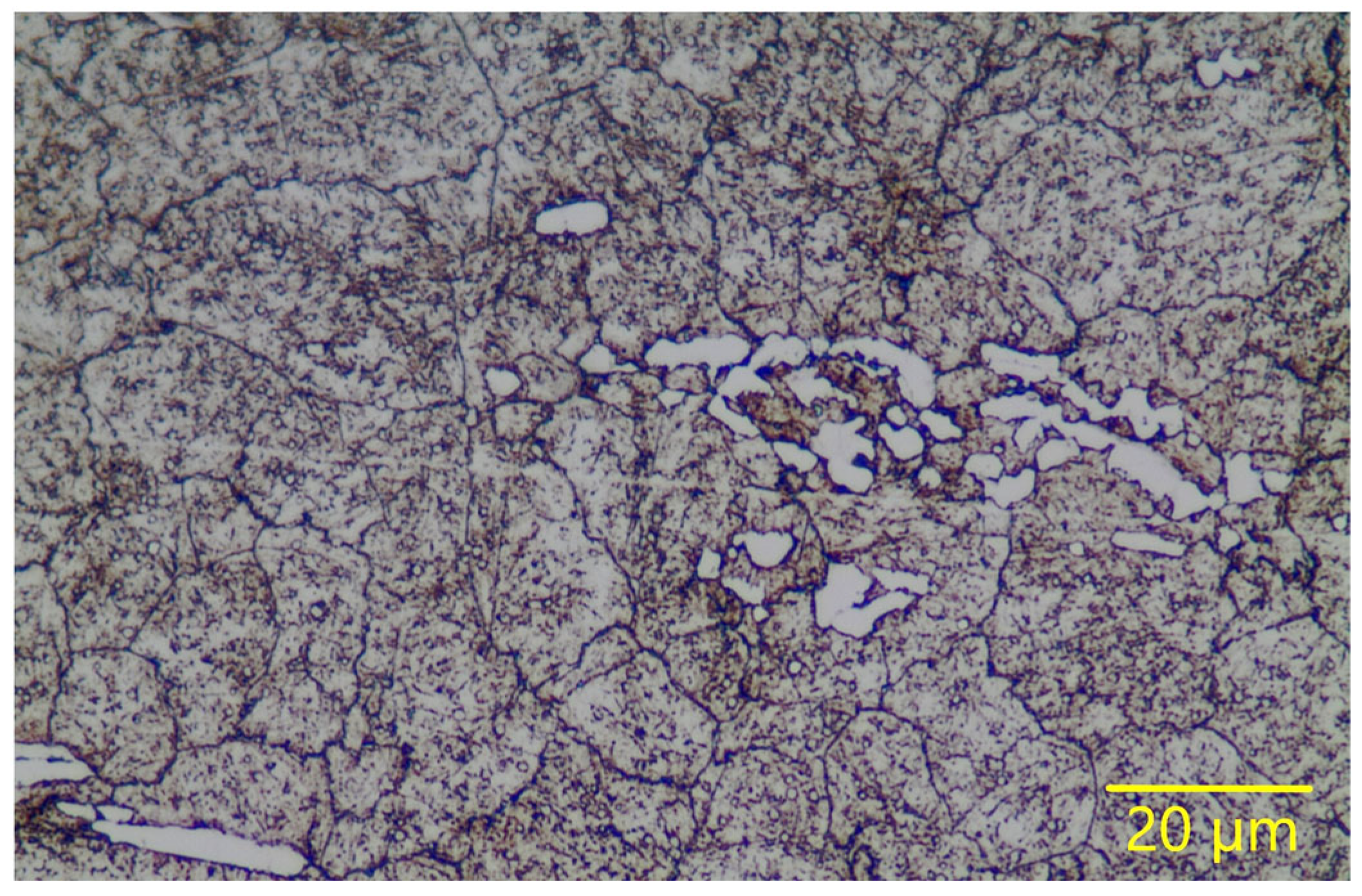
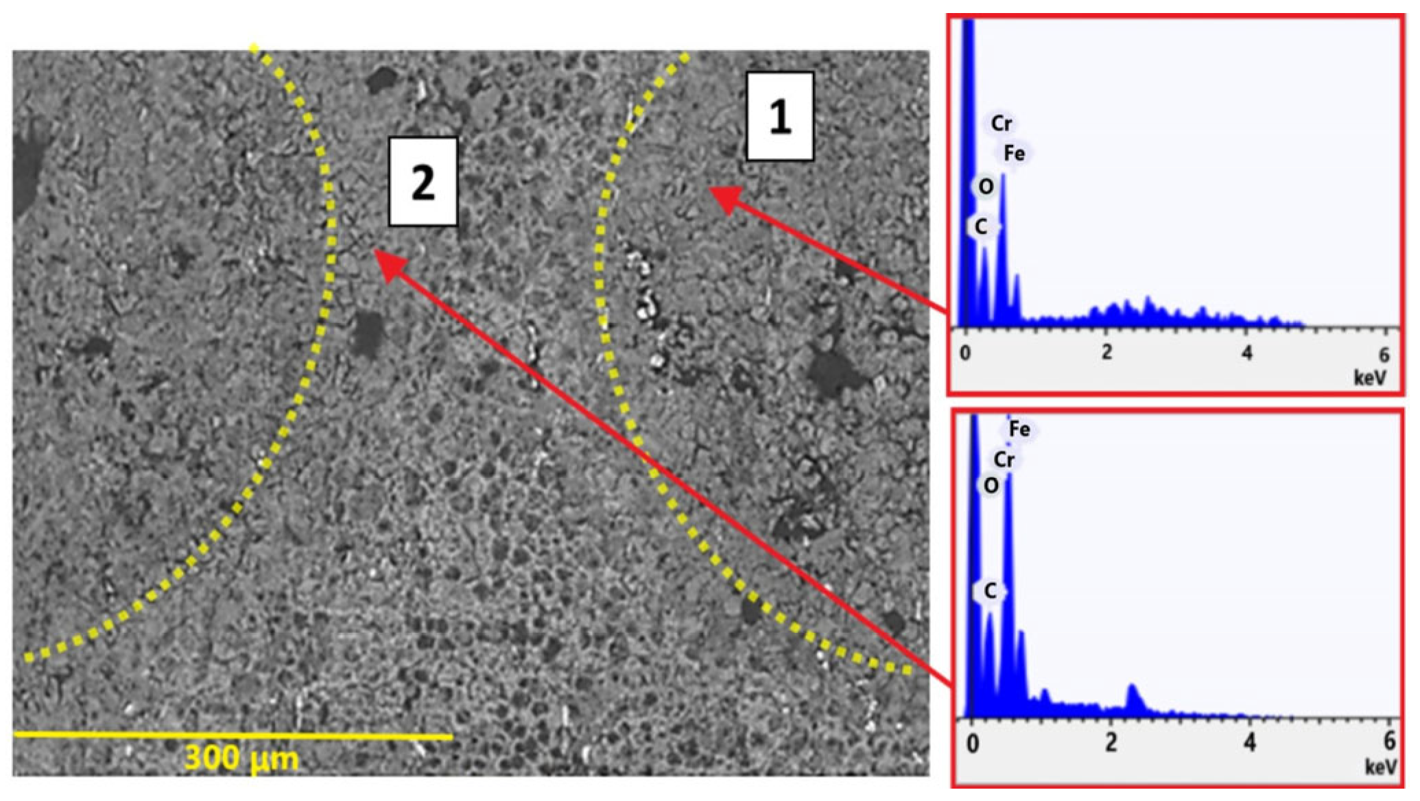
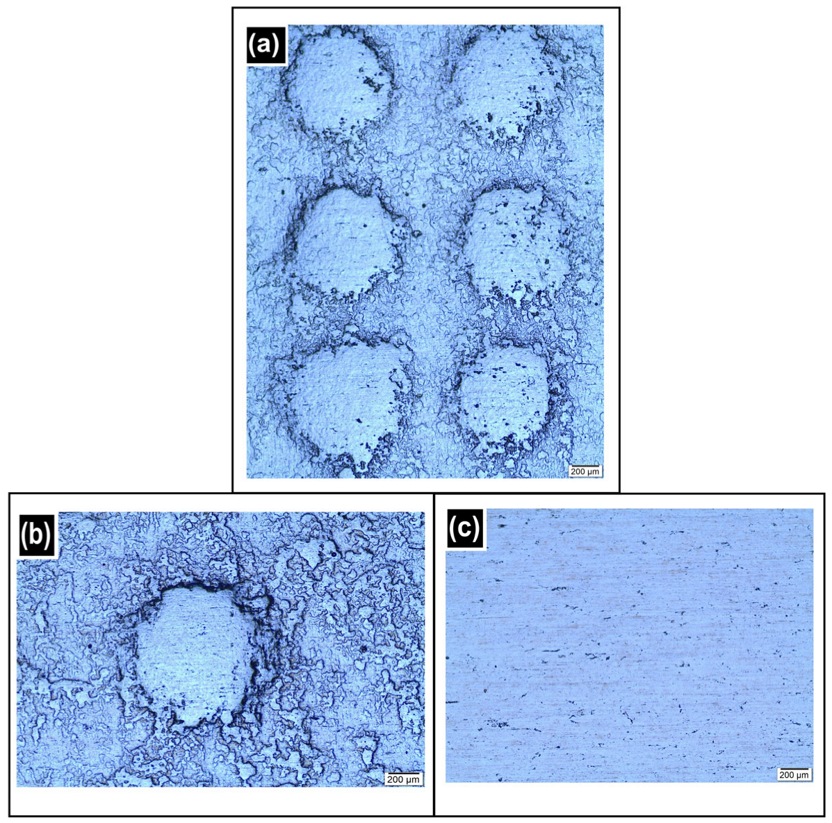
  • The anodic dissolution involved in texturing the samples from the work rolls occurs preferentially around the primary carbides, probably due to the depletion of alloying elements (Mo, V, Cr) for primary carbide formation, making these regions more susceptible to intense oxidation;
  • Additionally, a loss of mechanical support from the matrix due to the preferential removal of Fe, characteristic of the electrochemical texturing process, can favor the detachment of some of these carbides;
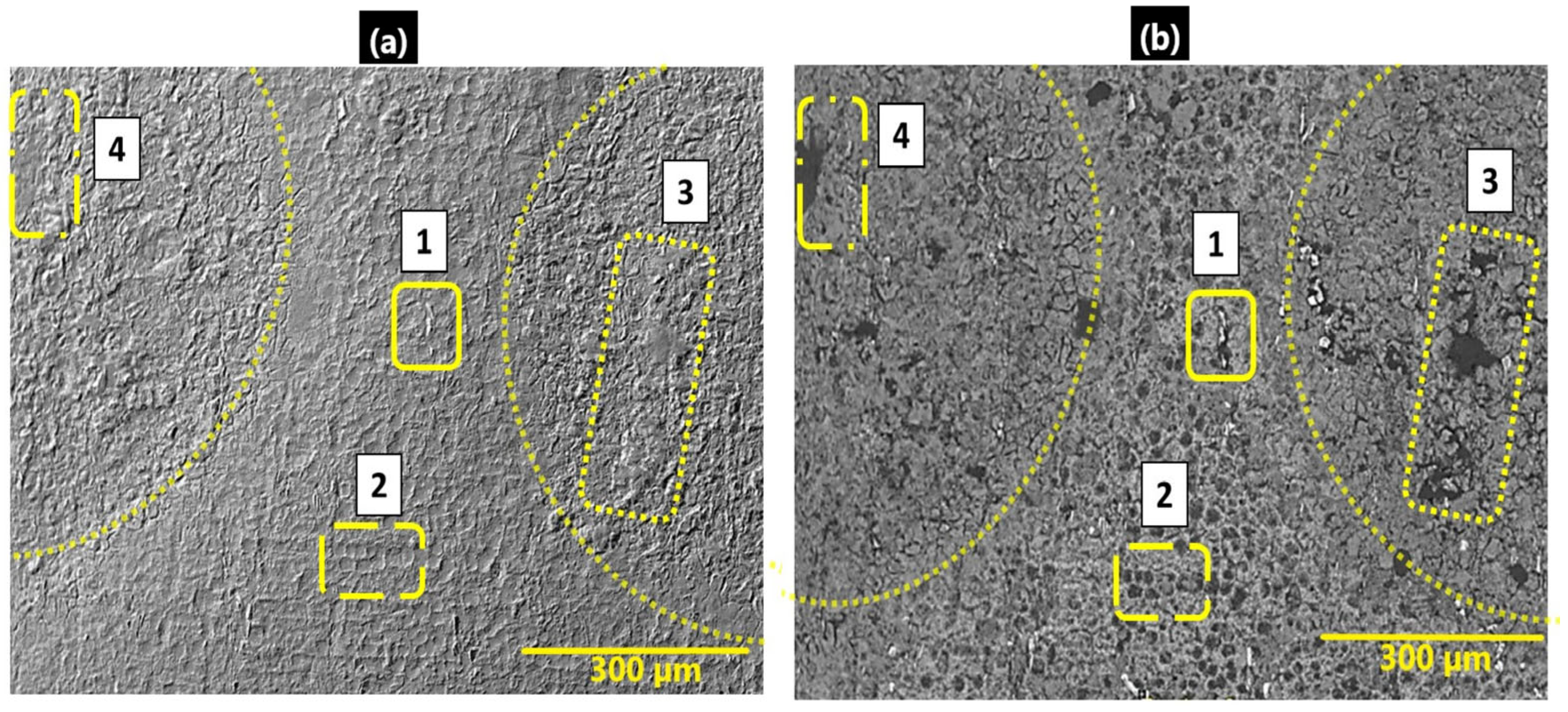
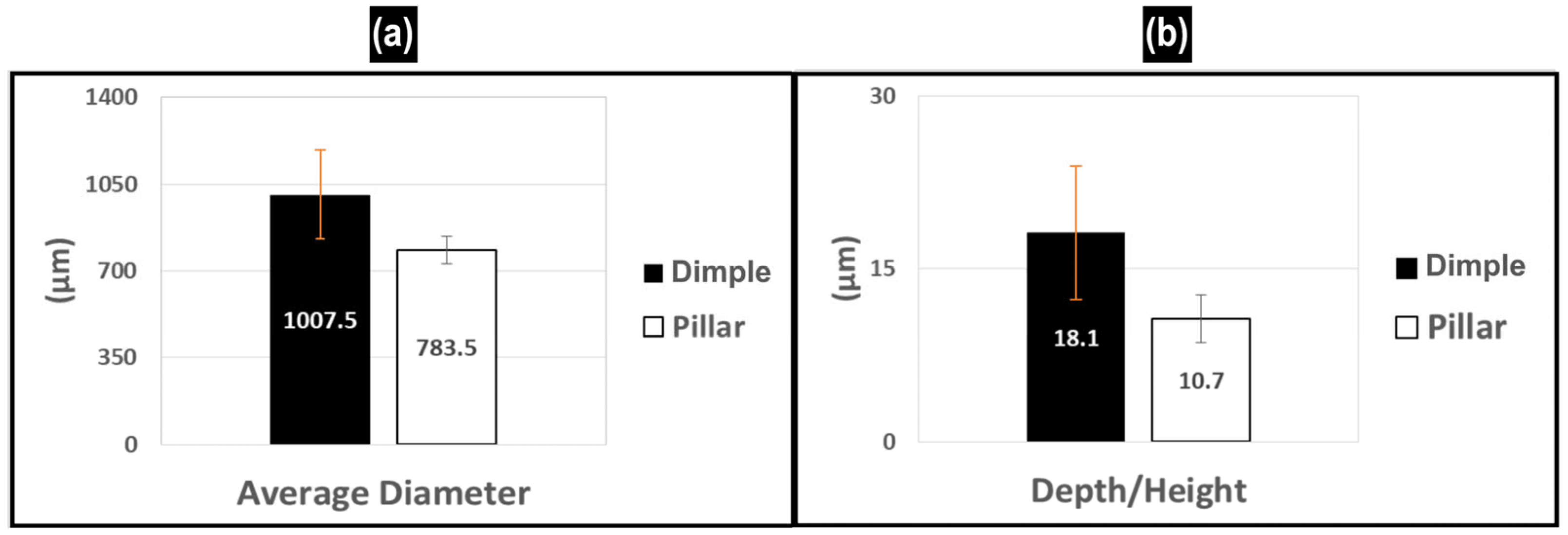
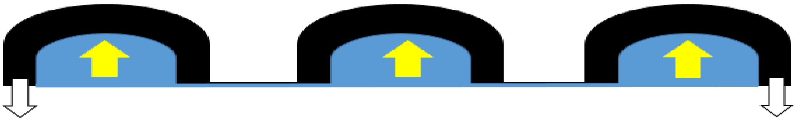
  • The textured dimples on the work roll surface were transferred as pillars to the sheet surfaces. However, the pillars produced on the sheet are not the exact negative of the dimples on the rolls. In other words, only a percentage of the texture is transferred to the sheets.

5. Patents

The texturing roll chamber developed in this study is currently under a patent process at INPI/Brazil, number BR1020240215745.

Author Contributions

Conceptualization, H.L.C. and W.L.; methodology, P.L.M.J. and C.d.A.C.; resources, H.L.C. and W.L.; investigation, P.L.M.J.; writing—original draft preparation, P.L.M.J. and W.M.D.S.J.; writing—review and editing, H.L.C.; supervision, H.L.C. and W.M.D.S.J. All authors have read and agreed to the published version of the manuscript.

Funding

This research was funded by the CNPq/Brazil via INCT CT Trib (grant number 406654/2022-0). PLM received a scholarship from Capes/Brazil.

Data Availability Statement

All relevant data are included in this manuscript.

Conflicts of Interest

W.L declares that he works for Aperam South America. The other authors declare no conflicts of interest. The funders had no role in the design of the study; in the collection, analyses, or interpretation of data; in the writing of the manuscript; or in the decision to publish the results.

References

  1. Junior, P.L.M.; Labiapari, W.S.; Da Silva, W.M.J.; Costa, H.L. Durability of Deterministic Textures Produced by Maskless Electrochemical Texturing (Mect) During Skin Pass Cold Rolling. Wear 2025, 562, 205638. [Google Scholar]
  2. Monteiro, P.L.; Costa, H.L. A Holistic Review of Surface Texturing in Sheet Metal Forming: From Sheet Rolling to Final Forming. Lubricants 2025, 13, 253. [Google Scholar] [CrossRef]
  3. Steinhoff, K.; Rasp, W.; Pawelski, O. Development of deterministic-stochastic surface structures to improve the tribological conditions of sheet forming processes. J. Mater. Process. Technol. 1996, 60, 355–361. [Google Scholar] [CrossRef]
  4. Kijima, H. Mechanism of roughness profile transfer in skin-pass rolling of thin steel strip. JFE Tech. Rep. 2019, 24, 129–134. [Google Scholar]
  5. Rodriguez-Vidal, E.; Matthews, D.T.A.; de Viteri, V.S.; Korver, F.; Wentink, D.; Quintana, I. Surface design and texturing of strip steel using nanosecond pulsed lasers for simulated roughness transfer and paint appearance. J. Mater. Process. Technol. 2020, 275, 116365. [Google Scholar] [CrossRef]
  6. Hong, M.H.; Tark, H.J.; Park, J.S.; Paik, D.J. Improvement of surface texture on the hot dip galvanized and galvannealed steel sheets. Metall. Ital. 2012, 13, 9–13. [Google Scholar]
  7. Çolak, B. A comparison of tonnage-dependent shot blast and electro-discharge texturing methods. Surf. Topogr. Metrol. Prop. 2021, 9, 035051. [Google Scholar] [CrossRef]
  8. Vermeulen, M.; Scheers, J. Micro-hydrodynamic effects in EBT textured steel sheet. Int. J. Mach. Tools Manuf. 2001, 41, 1941–1951. [Google Scholar] [CrossRef]
  9. Gorbunov, A.; Belov, V.; Begletsov, D. Texturing of rollers for the production of auto-industry sheet. Steel Transl. 2009, 39, 696. [Google Scholar] [CrossRef]
  10. Hilgenberg, K.; Steinhoff, K. Texturing of skin-pass rolls by pulsed laser dispersing. J. Mater. Process. Technol. 2015, 225, 84–92. [Google Scholar] [CrossRef]
  11. Köhler, K.; Kwiaton, N.; Bretschneider, M. Skin pass rolling of high manganese steels. Mater. Sci. Forum 2016, 854, 93–98. [Google Scholar] [CrossRef]
  12. de Argandoña, E.S.; Mendez, M.; Mendiguren, J.; Zabala, A. Tool surface texturing by shot peening: Initial results and lessons learned. Proc. IOP Conf. Ser. Mater. Sci. Eng. 2024, 1307, 012017. [Google Scholar] [CrossRef]
  13. Simao, J.; Apinwall, D.; Wise, M.; Subari, K. Surface texture transfer in simulated tandem and temper mill rolling using electrical discharge textured rolls. J. Mater. Process. Technol. 1996, 56, 177–189. [Google Scholar] [CrossRef]
  14. Evin, E.; Tomáš, M.; Kmec, J. Optimization of Electro-Discharge Texturing Parameters for Steel Sheets’ Finishing Rollers. Materials 2020, 13, 1223. [Google Scholar] [CrossRef] [PubMed]
  15. Elkoca, O. A study on the characteristics of electrical discharge textured skin pass mill work roll. Surf. Coat. Technol. 2008, 202, 2765–2774. [Google Scholar] [CrossRef]
  16. Gonçalves, J., Jr.; De Mello, J.; Costa, H. Tribological behaviour of alternative surface modifications for cold rolling mill rolls. Wear 2021, 470, 203614. [Google Scholar] [CrossRef]
  17. Zhang, K.; Deng, J.; Lei, S.; Yu, X. Effect of micro/nano-textures and burnished MoS2 addition on the tribological properties of PVD TiAlN coatings against AISI 316 stainless steel. Surf. Coat. Technol. 2016, 291, 382–395. [Google Scholar] [CrossRef]
  18. Warneke, P.; Bohlen, A.; Seefeld, T. Texturing skin-pass rolls by high-speed laser melt injection, laser ablation, and electrolytic etching. J. Laser Appl. 2024, 36, 012011. [Google Scholar] [CrossRef]
  19. Pawelski, O.; Rasp, W.; Zwick, W.; Nettelbeck, H.-J.; Steinhoff, K. The influence of different work-roll texturing systems on the development of surface structure in the temper rolling process of steel sheet used in the automotive industry. J. Mater. Process. Technol. 1994, 45, 215–222. [Google Scholar] [CrossRef]
  20. Shimizu, I.; Andreasen, J.L.; Bech, J.I.; Bay, N. Influence of workpiece surface topography on the mechanisms of liquid lubrication in strip drawing. J. Trib. 2001, 123, 290–294. [Google Scholar] [CrossRef]
  21. Zhang, Z.-Q.; Liao, X.; Ren, Z.-K.; Wang, Z.-H.; Liu, Y.-X.; Wang, T.; Huang, Q.-X. Effect of two-pass rolling of textured roll and polished roll on surface topography and mechanical properties of 316L stainless steel ultra-thin strip. J. Iron Steel Res. Int. 2025, 32, 186–197. [Google Scholar] [CrossRef]
  22. Zabala, A.; Galdos, L.; Childs, C.; Llavori, I.; Aginagalde, A.; Mendiguren, J.; Saenz de Argandoña, E. The interaction between the sheet/tool surface texture and the friction/galling behaviour on aluminium deep drawing operations. Metals 2021, 11, 979. [Google Scholar] [CrossRef]
  23. Menezes, P.L.; Kishore; Kailas, S.V. Influence of Die Surface Textures during Metal Forming—A Study Using Experiments and Simulation. Mater. Manuf. Process. 2010, 25, 1030–1039. [Google Scholar] [CrossRef]
  24. Zhang, K.; Deng, J.; Meng, R.; Lei, S.; Yu, X. Influence of laser substrate pretreatment on anti-adhesive wear properties of WC/Co-based TiAlN coatings against AISI 316 stainless steel. Int. J. Refract. Met. Hard Mater. 2016, 57, 101–114. [Google Scholar] [CrossRef]
  25. Shrivastava, A.; Kumar, D.R.; Manikandan, G.; Verma, R.K. Laser surface texturing of dies in strip drawing of DP600 steel sheet. Surf. Eng. 2023, 39, 870–881. [Google Scholar] [CrossRef]
  26. Patel, D.S.; Jain, V.; Shrivastava, A.; Ramkumar, J. Electrochemical micro texturing on flat and curved surfaces: Simulation and experiments. Int. J. Adv. Manuf. Technol. 2019, 100, 1269–1286. [Google Scholar] [CrossRef]
  27. Patel, D.S.; Agrawal, V.; Ramkumar, J.; Jain, V.; Singh, G. Micro-texturing on free-form surfaces using flexible-electrode through-mask electrochemical micromachining. J. Mater. Process. Technol. 2020, 282, 116644. [Google Scholar] [CrossRef]
  28. Galanin, S.I.; Viskovatyi, I.S. Electrochemical Surface Texturing of Silver. Surf. Eng. Appl. Electrochem. 2015, 51, 332–338. [Google Scholar] [CrossRef]
  29. Kunar, S.; Bhattacharyya, B. Fabrication of various micropatterns by maskless micro-electrochemical texturing. Manuf. Rev. 2019, 6, 6. [Google Scholar] [CrossRef]
  30. Hao, X.Q.; Wang, L.; Ding, Y.C.; Guo, F.L.; Lu, B.H. Finite Element Analysis of a Mask-Less Electrochemical Texturing (MECT) Method on Metallic Surface. Adv. Sci. Lett. 2011, 4, 1394–1398. [Google Scholar] [CrossRef]
  31. Rodrigues, T.A.; Arencibia, R.V.; Costa, H.; da Silva, W.M., Jr. Roughness analysis of electrochemically textured surfaces: Effects on friction and wear of lubricated contacts. Surf. Topogr. Metrol. Prop. 2020, 8, 024011. [Google Scholar] [CrossRef]
  32. Dias, L.C.; Ferri, G.G.B.; Costa, H.L. Maskless electrochemical surface texturing for cylindrical components: New developments. J. Braz. Soc. Mech. Sci. Eng. 2024, 46, 297. [Google Scholar] [CrossRef]
  33. Wu, C.; Zhang, L. Surface texture transfer in skin-pass rolling under mixed lubrication. Int. J. Mech. Sci. 2025, 286, 109858. [Google Scholar] [CrossRef]
  34. Zhang, B.; Meng, W.J. Scaling Anomaly in the Mechanical Response in Microscale Reverse Extrusion of Copper. J. Micro Nano-Manuf. 2020, 8, 010910. [Google Scholar] [CrossRef]
  35. Wentink, D.; Matthews, D.; Appelman, N.; Toose, E. A generic model for surface texture development, wear and roughness transfer in skin pass rolling. Wear 2015, 328, 167–176. [Google Scholar] [CrossRef]
  36. Steinhoff, K.; Bünten, R.; Rasp, W.; Kopp, R.; Pawelski, O. Development of a model for the simulation of the transfer of surface structure in the temper-rolling process. Steel Res. 1995, 66, 520–525. [Google Scholar] [CrossRef]
  37. Silva, R.S.; Lopes, A.P.O.; Luz, F.K.C.; de Almeida, D.T.; Costa, H.L. Effect of tool microstructure on the tribological behaviour of electrochemically textured tools in strip drawing tests. Wear 2025, 571, 205759. [Google Scholar] [CrossRef]
  38. Ray, S. Principles and Applications of Metal Rolling; Cambridge University Press: Cambridge, UK, 2016. [Google Scholar]
  39. Bünten, R.; Steinhoff, K.; Rasp, W.; Kopp, R.; Pawelski, O. Development of a FEM-model for the simulation of the transfer of surface structure in cold-rolling processes. J. Mater. Process. Technol. 1996, 60, 369–376. [Google Scholar] [CrossRef]
  40. Miguel, V.; Martínez, A.; Coello, J.; Avellaneda, F.J.; Calatayud, A. A new approach for evaluating sheet metal forming based on sheet drawing test. Application to TRIP 700 steel. J. Mater. Process. Technol. 2013, 213, 1703–1710. [Google Scholar] [CrossRef]
  41. Azushima, A.; Kudo, H. Direct observation of contact behaviour to interpret the pressure dependence of the coefficient of friction in metal forming. Ann. CIRP 1995, 44, 209–212. [Google Scholar] [CrossRef]
  42. Belov, V.; Begletsov, D.; D’yakova, M.; Gorbunov, A. Production of sheet with regulated surface microtopography. Steel Transl. 2014, 44, 298–305. [Google Scholar] [CrossRef]
  43. Costa, H.L.; Profito, F.J.; Zhang, X.; Thole, K.A. Optimizing the surface of manufactured components for friction, adhesion, and convective heat transfer. MRS Bull. 2022, 47, 1247–1259. [Google Scholar] [CrossRef]
  44. Yerramareddy, S.; Bahadur, S. The effect of laser surface treatments on the tribological behavior of Ti-6Al-4V. Wear 1992, 157, 245–262. [Google Scholar] [CrossRef]
  45. Mondal, A.K.; Kumar, S.; Blawert, C.; Dahotre, N.B. Effect of laser surface treatment on corrosion and wear resistance of ACM720 Mg alloy. Surf. Coat. Technol. 2008, 202, 3187–3198. [Google Scholar] [CrossRef]
  46. Jonasson, M.; Pulkkinen, T.; Gunnarsson, L.; Schedin, E. Comparative study of shotblasted and electrical-discharge-textured rolls with regard to frictional behavior of the rolled steel sheet surfaces. Wear 1997, 207, 34–40. [Google Scholar] [CrossRef]
  47. Merlo, A.; Léonard, G. Magnetron Sputtering vs. Electrodeposition for Hard Chrome Coatings: A Comparison of Environmental and Economic Performances. Materials 2021, 14, 3823. [Google Scholar] [CrossRef] [PubMed]
Figure 1. Layout of the methodology.
Lubricants 13 00312 g001
Figure 2. Illustration of the electrolyte flow parallel to the gap between the cathode and anode. The mask highlighted in red contains darker regions representing laser perforations; the workpiece highlighted in gray contains black regions representing textures produced by MECT.
Lubricants 13 00312 g002
Figure 3. Developed chamber: (a) MECT chamber assembly; (b) sketch of the anode and cathode with dimensions in mm.
Lubricants 13 00312 g003
Figure 4. Procedure for extracting flat surface samples from work rolls. The dimensions of the work roll are in mm.
Lubricants 13 00312 g004
Figure 5. Microstructure of the work roll material.
Lubricants 13 00312 g005
Figure 6. Scheme of the work roll texturing chamber: (a) sectional view highlighting the radial bearing housing for shaft rotation, the threaded connection for cathode displacement, and the electrolyte flow path through the gap between cathode and anode; (b) external view of the assembled chamber; (c) cutaway view showing the internal arrangement of the electrode system and the roll.
Lubricants 13 00312 g006
Figure 7. Textured AISI 1010 steel sample: (a) topographic top view; (b) 3D map; (c) surface profile of a region between dimples; (d) surface profile intersecting a row of dimples; (e) SEM image using secondary electrons (SE).
Lubricants 13 00312 g007
Figure 8. AISI 1010 steel sample: (a) scanning electron microscopy image obtained via SE with compositional maps of (b) Fe, (c) O, and (d) C. The analyses were performed in a region outside the dimples.
Lubricants 13 00312 g008
Figure 9. Textured flat sample from the work roll: (a) interferometry; (b) 3D interferometry; (c) surface profile of a region between dimples; (d) surface profile intercepting a row of dimples.
Lubricants 13 00312 g009
Figure 10. SEM (SE) images of a textured flat sample of the work roll showing (a) uniform dimple array and (b) surface topography characteristics.
Lubricants 13 00312 g010
Figure 11. SEM image via BSE of a rolling roll sample with EDS analysis. The semicircles indicate the dimples.
Lubricants 13 00312 g011
Figure 12. (a) SEM images of a textured roll sample inside a dimple (left) via BSE and (right) via SE. The outlined rectangles highlight regions of interest. (b) BSE-SEM image of a region outside the dimples on a textured rolling roll sample with EDS analysis; (c) surface analysis before texturing.
Lubricants 13 00312 g012
Figure 13. SEM images of the surface of a textured rolling roll sample: (a) SE and (b) BSE.
Lubricants 13 00312 g013
Figure 14. Topography analysis: (a) Interferometry of the replica of the work roll surface; the surface was inverted on the z-axis; (b) interferometry of the rolled sheet; (c) surface profile corresponding to the traced line in (b).
Lubricants 13 00312 g014
Figure 15. Analysis of the dimensions of the textures: (a) average diameter of the dimples in the work roll and of the pillars on the surface of the rolled sheet; (b) average maximum depth of the dimples in the work roll and average maximum height of the pillars on the rolled sheet.
Lubricants 13 00312 g015
Figure 16. Optical microscopy (OM) images of the AISI 430 steel sheet: (a) after the cold rolling test; (b) a single pillar; (c) before the rolling tests.
Lubricants 13 00312 g016
Figure 17. Formation of the pillars on the sheet (in blue) due to their reverse extrusion into the dimples of the roll (in black).
Lubricants 13 00312 g017
Table 1. MECT texturing parameters used in this study for flat surface samples.
Gap (µm)NaCl Concentration (g/L)Flow (mL/s)Tension (V)Time (s)
1002002030300
Table 2. Chemical composition of the work roll (wt.%).
CSiMnCrMoNiVFe
0.850.250.384.168.130.202.24Balance
Table 3. Texturing test parameters used for the pilot cold rolling work roll.
Gap (µm)NaCl Concentration (g/L)Flow (mL/s)Tension (V)Time (s)
3002002030300
Table 4. Nominal chemical composition of the sheet material (AISI 430).
CMnSiPSCrNbN
wt.%
0.0210.200.310.0300.00116.150.3360.0184
Disclaimer/Publisher’s Note: The statements, opinions and data contained in all publications are solely those of the individual author(s) and contributor(s) and not of MDPI and/or the editor(s). MDPI and/or the editor(s) disclaim responsibility for any injury to people or property resulting from any ideas, methods, instructions or products referred to in the content.

