Abstract
The control of lubricity induced by electric potential is appealing for numerous applications. On the other hand, the high polarity of ionic liquids facilitates the adsorption of equally charged molecules onto polar surfaces. This phenomenon and its consequences are well understood at the nanoscale; however, they have recently garnered significant attention at the macroscale. This study investigates the lubricity of trihexyltetradecylphosphonium dicyanamide, a phosphonium ionic liquid, when used as a neat lubricant in reciprocating sliding under electrically charged conditions. Two different polarities with the same potential were applied to the friction pair of bearing steel against bearing steel while monitoring electrical contact resistance. The lubricity was evaluated through measurements of friction, wear, surface morphology, and composition. It was found that the application of electric potential significantly alters the lubricity of the investigated ionic liquid where a positive potential applied to the ball resulted in the least damaging situation. The recorded electrical contact resistance enabled the monitoring of tribofilm formation during reciprocation. It was found that there was minimal to no separation between interacting surfaces when the ball was changing direction.
1. Introduction
Ionic liquids (ILs) are a revolutionary lubricant class, providing eco-friendly alternatives to traditional lubricants, especially for steel-on-steel lubrication. Phosphonium-based ILs stand out for their remarkable attributes that effectively minimise friction and wear in demanding tribological applications. Their key features, such as broad electrochemical stability, high ion mobility, and negligible vapour pressure, make phosphonium ILs ideal for extreme lubrication conditions [1,2,3].
Phosphonium ILs excel in tribology due to their formation of protective boundary films on metal surfaces, reducing direct contact, wear, and friction. The stability of these lubricant films is mainly governed by phosphonium cations’ interaction with steel surfaces. However, the performance of these ILs is also significantly influenced by the anion component [4,5]. Research shows that modifying the architecture of anions in phosphonium ionic liquids can significantly affect their lubrication properties, enabling the customisation of ILs for specific operational needs [1,6].
A key feature that sets phosphonium-based ILs apart from other lubricants is the distinctive interaction between their cationic and anionic layers during friction. The stability and strength of these ionic layers are essential for sustaining lubrication effectiveness across different operating conditions, including temperature, pressure, and sliding speed. Notably, the cationic layers possess a larger molecular structure than ammonium-based cations, demonstrating unique electrochemical and thermal stability properties crucial for preserving stable interfaces during friction [7]. At higher temperatures, these ionic liquids maintain stability, improving their lubricating abilities by fostering the creation of efficient protective films [8,9].
The interaction of phosphonium cations with steel surfaces is mainly determined by Coulombic forces, which are shaped by the surface potential of the friction pair. When these surfaces contact, the electrostatic interactions between the cations and the surface create dense ionic layers that help protect the metal from wear. Additionally, the anionic layer is crucial, as the composition of anions can influence the thickness and stability of the protective tribofilms. Some anions, when decomposed during friction, promote the development of sacrificial or protective layers, preventing direct contact [1,4,10]. Additionally, the equilibrium between layers rich in cations and anions significantly affects lubrication efficiency. Under certain conditions, layers abundant in cations enhance lubrication, suggesting that the balance of electrostatic interactions at the metal interface is essential for optimal friction reduction [11].
Another significant phenomenon observed when an ionic liquid is positioned between two potential-bearing surfaces is the overscreening and crowding of ions on these surfaces. These phenomena strongly depend on the magnitude of the potential [12,13,14,15]. The potential-dependent alignment of cations and anions can drastically change the properties of the ionic liquid as a lubricant from liquid to solid-like behaviour [16]. The response of ionic liquids to an electric field has opened up a niche for another scientific innovation—tribo-tronics, and the possibility of controlling the ionic boundary layer [17,18,19].
The behaviour of ionic layers is also affected by external factors like pressure and shear forces. When exposed to high-pressure environments, the adsorption of phosphonium ions onto the steel surface increases because of heightened intermolecular forces, resulting in stronger and more stable boundary layers. Consequently, these improved layers significantly minimise friction and wear [4]. Conversely, the lubricating films might fail to attach properly to the surface at low-pressure conditions, undermining their effectiveness. Likewise, shear forces generated by friction can deform or break down the lubricant films, leading to direct contact and wear on metal surfaces. With increasing shear rates, the integrity of the ionic layers may be compromised, adversely affecting the lubricant’s overall performance [20,21]. The molecular dynamics of phosphonium-based ionic liquids in friction demonstrate their remarkable resilience and adaptability to fluctuating tribological conditions. The kinetics of interaction between the ionic layers and the surface show that these films can flexibly respond to different stress levels, providing ongoing lubrication even in demanding operational situations [4]. The combination of adaptability and the ionic layers’ high thermal stability positions phosphonium ILs as a strong candidate for high-performance lubrication in industrial applications.
A key factor in the performance of phosphonium ILs in tribology is how they interact with metal surfaces, especially concerning the formation and stability of interfacial double layers. This interaction becomes complex when opposing surface potentials exist between the friction pair. The behaviour of ionic layers in these scenarios, where cations and anions are subject to conflicting surface potentials, directly impacts the stability of lubricating films and the overall efficacy of ILs as lubricants. Moreover, the electrostatic interactions between the larger, more structured phosphonium cations and the anions play a significant role in developing these double layers [22]. Research indicates that the anionic element is vital for the stability and function of the electric double layer, particularly when influenced by changing electric fields and surface potentials [23,24]. Additionally, environmental factors like temperature, pressure, and sliding velocity affect the creation of boundary films. As the temperature rises, phosphonium ILs show improved ionic mobility, facilitating the quick development of protective films on the steel surface, which helps diminish wear [4,25]. Pressure influences the ionic liquid’s capacity to bond with the metal surface, where high-pressure settings encourage stronger cation adsorption, thereby improving the protective film’s efficiency [26]. Studies also show that roughness reduces IL layering and alters squeeze-out forces, which is likely due to molecular entrapment and hindered flow [27].
Even with progress in comprehending phosphonium ILs’ behaviour, significant gaps persist. The stability and dynamic interactions of the cationic and anionic layers, especially under opposing surface potentials, remain incompletely understood. Kornyshev has emphasised the need for a paradigm shift in conceptualising ionic liquid double layers, suggesting that current models may not adequately describe these systems’ complexity [28]. Spikes, in his review, highlighted the need to understand IL’s behaviour in realistic two-electrode charging conditions when interacting surfaces have opposite charges [29]. Investigating the influence of anion architecture, molecular interactions under shear stress, and the impact of applied electric potentials on lubrication mechanisms is essential to fully realise the potential of these ionic liquids in tribological applications [1,11]. In summary, the lubrication capabilities of phosphonium-based ILs are closely connected to the dynamics of their cationic and anionic layers during friction. These layers’ stability, structure, and interactions significantly affect their capacity to develop protective films, which help minimise friction and wear in steel-on-steel contact scenarios. Gaining insights into these intricate interactions is vital for refining phosphonium ILs, ensuring they remain effective across various operating conditions. Therefore, this study aims to examine changes in the lubricity of phosphonium IL under applied electric potentials between oppositely charged interacting surfaces.
2. Materials and Methods
2.1. Materials Used
The trihexyltetradecylphosphonium dicyanamide ionic liquid, CAS No. 701921-71-3, purchased from Sigma Aldrich (St. Louis, MO, USA), was used as a neat lubricant in these experiments. According to the supplier, it has an electric conductivity of 0.16 mS/cm (@ 24 °C). The ionic liquid was used as received; no drying or purification was applied. At the tribo-test temperature of 80 °C, its kinematic viscosity was 44.2 mm2/s. The molecular structure of the investigated IL is presented in Figure 1.
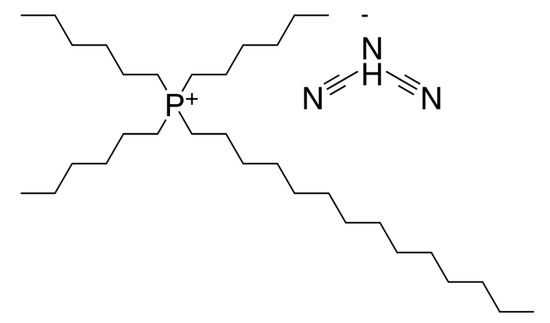
Figure 1.
Molecular structure of trihexyltetradecylphosphonium dicyanamide ionic liquid.
The acetone, toluene, and isopropanol used during cleaning procedures were purchased from Sigma Aldrich.
2.2. Tribo-Tests Procedure
The tribological tests were conducted using a reciprocating ball-on-plate Ducom TR-282 tribometer equipped with a system for applying electric voltage and measuring electric contact resistance (ECR). During the tribo-test, a ball (φ 6 mm) made of bearing steel was rubbed against a plate (φ 10 mm, 3 mm thick) composed of the same steel. The hardness and surface roughness Ra of the ball and plate specimens were 850 HV and 0.05 µm, and 190 HV and 0.02 µm, respectively. The certified specimens were obtained from Pacific Sensor Services, LLC (Carrollton, TX, USA). The tests were performed under the following conditions: a load of 4 N, an initial contact pressure of 1.05 GPa, a stroke length of 1 mm, a reciprocation frequency of 15 Hz, test temperatures of 80 °C, a lubricant volume of 100 µL, and a total test duration of 7200 s. The selection of specific tribo-test parameters aimed to replicate harsh lubrication conditions, which are characterised by high contact pressure combined with varying sliding speeds and changing directions. The ball position was measured using a Hall sensor. Prior to testing, all components in contact with the lubricant were thoroughly cleaned using toluene and acetone.
Figure 2 illustrates the external potential application schemes where three cases are examined: (i) no voltage applied, (ii) a positive (higher) potential applied to the ball, and (iii) a negative potential applied to the ball. The latter two cases facilitated the measurement of ECR. The corresponding electric voltage was applied prior to commencing the tribological test, and ECR measurements began. After 15 to 16 s, the tribo-test was started. During the tribo-test, the coefficient of friction (COF), ECR, and ball position were continuously recorded. The mean COF was calculated from steady-state friction, considering the last 5000 s of each tribo-test. The tribo-tests were conducted in triplicate.

Figure 2.
Tribo-test schemes, including external potential application.
2.3. Equipment for External Potential Application and ECR Measurement
In the present case, the plate holder was insulated from the stage to allow current flow only through the tribo-contact. The flexible wires from the power supply circuit were connected to the ball and plate holders. They were swapped to change polarity. The electric circuit scheme was partly made with reference to Yamaguchi et al. [30], where the 1.5 VDC was supplied to the circuit with a maximum current of 14.56 µA in the case of a short circuit. To imitate more realistic macroscale conditions, neither the voltage nor the current was constant during the experiment. Our previous paper described the specific equipment used in this experiment in detail [31].
The voltages were recorded at 10 kHz using a high-speed ADC board PCIE-1816H. Electrical contact resistance was determined by scaling the measured voltage values according to the established relationship and is referenced in this paper as instantly measured electrical contact resistance (mECR). During the 15 Hz reciprocating motion, over 300 measurements were taken as the ball moved between endpoints. The average electrical contact resistance (aECR) was calculated by averaging 1000 mECR values to observe and understand general trends more swiftly.
2.4. Worn Surface Analysis
Before the inspection, the worn surfaces were cleaned in an ultrasonic bath with acetone for five minutes. A Nikon ECLIPSE MA 100 (Nikon, Japan) optical microscope and a Hitachi 3400N (Hitachi, Tokyo, Japan) scanning electron microscope (SEM) were employed to inspect wear scars. A Bruker Quad 5040 (Bruker, Berlin, Germany) energy-dispersive spectroscopy (EDS) was used to analyse the composition of wear scars. The cross-section profiles of the wear traces generated on the plate were measured using a Mahr GD-25 stylus profilometer (Mahr GmbH, Göttingen, Germany). From the acquired profiles, the area of the wear trace profile was calculated and multiplied by the length of the wear trace to determine the wear volume.
3. Results
Figure 3 illustrates the mean coefficient of friction and wear volume obtained in the tribological test when external polarities are applied to the specimens. It also includes the test results observed without applied voltage. Lubricating the uncharged tribo-pair led to the lowest COF and negligible wear. The lubricity of IL significantly decreased with the introduction of current flow, where a negative potential applied to the ball resulted in a coefficient of friction twice as high and considerably increased wear. These results indicate that trihexyltetradecylphosphonium dicyanamide IL’s lubricity is susceptible to external potentials in the tribo-pair.
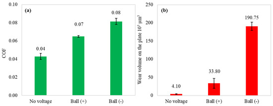
Figure 3.
Mean COF (a) and wear volume on the plate (b) of performed tribo-tests.
Figure 4 and Figure 5 illustrate the wear scars on the ball and the wear traces on the plate, respectively. Clearly, the wear mechanisms varied under different test conditions. Lubrication of the tribo-pair, when no voltage was applied, resulted in slight surface polishing. Residues of the tribo-film can be identified on both interacting surfaces. The electric potential established between the ball and the plate altered the lubrication conditions. Applying a positive potential to the ball led to increased wear, but the tribo-film remains visible on the worn surface. Moreover, the surfaces remain relatively smooth (Table 1). Despite the diminished lubricity, the positive charging of the harder ball surface does not result in extensive wear. Conversely, applying a negative potential to the ball leads to severe wear conditions, significantly diminishing the lubricity of the IL. In this case, the interacting surfaces underwent severe abrasive damage, adhesion, and material transfer. Applying a higher potential to the plate disrupts the formation of the lubrication layer, resulting in metal-to-metal interaction.

Figure 4.
The appearance of the wear scars on the balls.
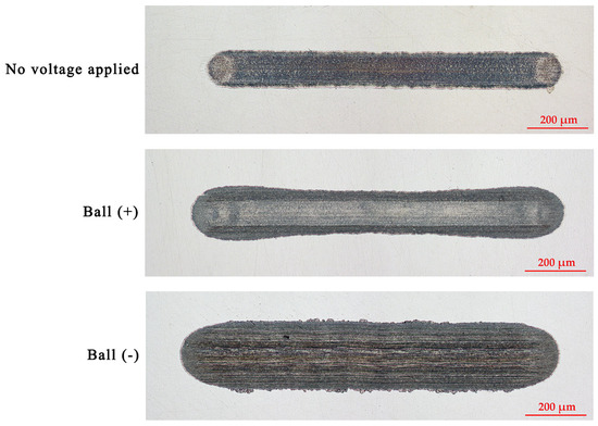
Figure 5.
The appearance of the wear traces on the plates.

Table 1.
The roughness of the wear traces measured perpendicular to the sliding direction.
The cross-section profiles of the wear traces highlight the lubrication situations (Figure 6). Even though applying a positive potential to the ball diminished the lubricity, the worn surfaces became smoother (Figure 6b). Some material was pushed out to the edges of the wear trace. In this case, a closer look at the worn surfaces reveals an erosive pattern where more erosion appears at the ends of the wear trace (Figure 7). The reciprocation resulted in different lubrication conditions along the wear trace. While more harsh lubrication conditions appeared at the ends of the wear trace, adhesion was observed in all the cases. In the ball (−) case, adhesion generated wear debris, which, acting in three-body wear, resulted in abraded worn surfaces. The conditions were not as severe in the middle of the wear trace.
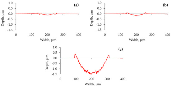
Figure 6.
Wear trace profiles on the plate, measured perpendicularly to the sliding direction. (a) No voltage applied; (b) ball (+); (c) ball (−).
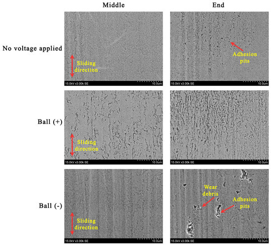
Figure 7.
SEM images illustrating the morphology in the middle and end of the wear trace.
The worn surface composition reveals the correlation between lubricity and the amount of carbon and oxygen (Table 2). The more worn surfaces underwent oxidation and had higher carbon content. The nitrogen was detected in all the wear traces, and its quantity was similar. Nitrogen was also detected outside the wear trace, indicating the adsorptive nature of IL and the activity of nitrogen. The cation’s phosphorus was not detected when the positive potential was applied to the ball.

Table 2.
EDS composition in the wear traces and outside the worn area.
As demonstrated above, the lubricity of the investigated IL varies significantly at different applied polarities. The parameters related to process dynamics, such as the coefficient of friction and electrical contact resistance, were analysed to gain further insights into the underlying mechanisms. The COF observed during the tribo-test, when no voltage was applied (Figure 8a), exhibits a variation pattern in which running-in and steady-state regimes can be identified. Applying a positive potential to the ball eliminated the running-in period, and the COF remained constant throughout the tribo-test (Figure 8b). It is important to note that the COF displays certain low-amplitude fluctuations and attains a higher value in this instance. The aECR remained relatively stable during this test, averaging approximately 100 kΩ. According to the literature, this value corresponds to the separation of interacting surfaces, which is also evident from the analysis of the worn surface [32]. Thus, the lubrication conditions were altered by applying a positive potential to the ball while the lubricating film or the adsorbed molecular layer continued to separate the surfaces.
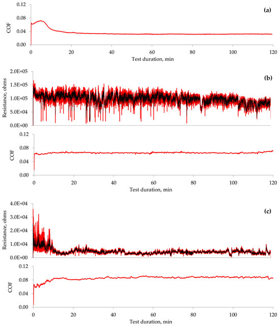
Figure 8.
Variation in COF and aECR during the tribo-tests: (a) no voltage applied; (b) ball (+); (c) ball (−). Note that the aECR scales differ for the polarities used.
Applying a negative potential to the ball resulted in the worst lubrication conditions among the cases examined. Running-in and steady-state regimes were noted (Figure 8c); however, the COF increased during the running-in phase. Subsequently, the COF remained constant in the steady-state regime, exhibiting low-amplitude fluctuations. The electrical contact resistance mirrored the COF variation. The higher aECR at the start of the tribo-test correlated with a lower COF. The reduced aECR measured less than 1 kΩ, indicating boundary lubrication conditions [32]. The analysis of the worn surface in this polarity scenario reveals abrasion and wear debris, which appear due to direct interaction between the ball and the plate.
The mECR at the onset of the tribo-test reveals the interaction process between the ball and the plate when they retain their initial micro-geometry. Moreover, due to the high contact pressure at the point of contact, the dynamics of tribo-film formation can be observed. The mECR patterns noted at the beginning of the tribo-tests are presented in Figure 9. According to the mECR recorded during the initial seconds of the ball (+) tribo-test, the tribo-film is rapidly developing, which results in the separation of the interacting surfaces. It is evident from the graph (Figure 9a) that the tribo-film formed in approximately 5 s when an mECR exceeding 100 kΩ was attained.
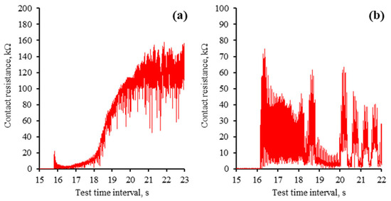
Figure 9.
Initial contact resistance across investigated polarity modes: (a) ball (+); (b) ball (−). Note that the scales of contact resistance (mECR) are different.
On the other hand, the ball (−) tribo-test exhibits a different mECR pattern (Figure 9b). The resistance demonstrated no discernible pattern in this test; a significant fluctuation from zero to several dozen kiloohms was observed. Therefore, it was speculated that the formation of the tribo-film was disrupted from the outset, leading to an increase in the coefficient of friction and poor lubricity during the steady-state period.
The reciprocating sliding is a complex movement involving constantly changing sliding speeds and stopping at the end of the wear trace. During this movement, the lubrication regime changes, and the harshest conditions occur at the ends of the wear trace. These changes were observed in worn surface morphology and monitored through mECR in conjunction with the ball movement. The analysis of such a process deepens the understanding of IL lubrication during reciprocating sliding when an electric potential is applied. Figure 10 and Figure 11 show the variation in mECR following the ball position. The curves represent ball reciprocation between end positions and the corresponding mECR at the particular ball position.
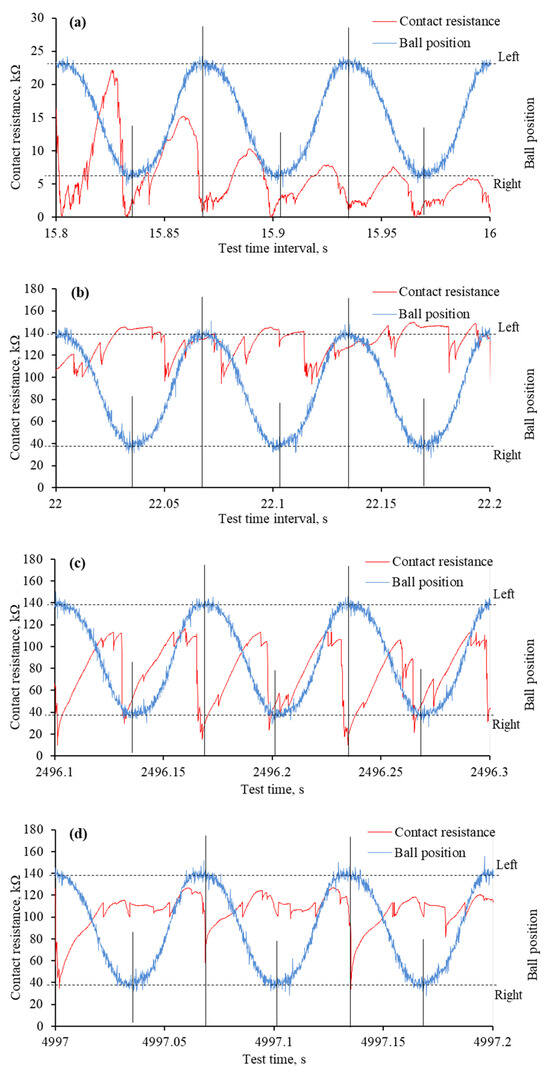
Figure 10.
The mECR variation and ball position during specific time intervals of tribo-tests when the positive potential was applied to the ball: (a) very first reciprocating cycles; (b) formation of tribo-film; (c) absence of the tribo-film at the ends of the wear trace; (d) absence of the tribo-film at one end of the wear trace. Note that the tribo-test started at 15.7 s.
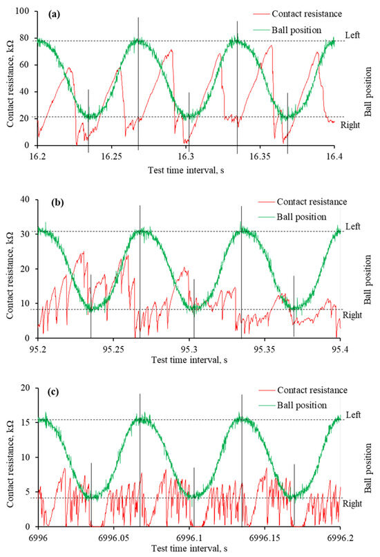
Figure 11.
The mECR variation and ball position during specific time intervals of tribo-tests when the negative potential was applied to the ball: (a) very first reciprocating cycles; (b) unstable tribo-film; (c) absence of surface separating tribo-film. Note that the tribo-test started at 16.15 s.
From the beginning of the test, when a positive potential is applied to the ball, the mECR varies in accordance with the ball’s position. In most cases, it is assigned a higher value when the ball moves, which is related to the viscosity and faster tribo-film formation. When the ball is at the end position or near it, the ECR drops sharply due to the establishment of better contact between the two interacting surfaces. Better electrical contact occurs due to poor tribo-film formation in harsh lubrication conditions and a larger contact area.
At the very beginning of the tribo-test, the mECR gradually decreased from approximately 20 kΩ to 5 kΩ, which was assigned to the rubbing of the initial surface micro-geometry (Figure 10a). A few published papers discussed this phenomenon through the influence of initial roughness and lubricant viscosity [32,33,34]. Even though the resistance had a higher value when the ball moved between endpoints, the mECR was almost zero at the ends of the wear trace, confirming the influence of viscosity. The continuous reciprocation led to a surface separating tribo-film, which was evident from the high mECR (Figure 10b). Interestingly, although the variation in mECR remained, it did not match the ball position, which means the tribo-film was built even at the ends of the wear trace.
As the tribo-test proceeded, the wear continued to propagate. It took a greater extent at the ends of the wear trace, which resulted in mECR drops at these points (Figure 10c). It is worth noting that tribofilms were sometimes formed at the ends during the test as well. This dynamic procedure was observed in mECR when one of the end positions exhibited higher resistance than the other (Figure 10d). It was also noted that the mECR gradually increased when the ball moved from one end position to another and dropped when it reached the end position (Figure 10c,d).
Substantially different mECR variation was observed when the ball was set to a negative potential. At the onset of the tribo-test, the high mECR was recorded when the ball was moving between endpoints (Figure 11a). It dropped sharply to near zero at the ends. Unfortunately, the maximum mECR values decreased as the test propagated, and it became difficult to distinguish between the ball positions (Figure 11b). The mECR increased and decreased spontaneously with sudden drops to zero. In most cases, these drops to zero mECR were at the end positions. When, according to Figure 8c, the aECR and COF were in a steady state, the mECR was zero at the ends of the wear trace, while during the movement, it fluctuated in the range of 5 kΩ (Figure 11c). Considering the mECR variation, the ball (−) polarity disturbed tribo-film formation, leading to direct asperity contact.
4. Discussion
The lubricity of ILs is strongly linked to the development of molecular layers on the surfaces that interact. Physical adsorption occurs under milder conditions and is replaced by chemisorption in more extreme conditions [3]. The surface charges control adsorption, leading to mixed molecular layers. Applying the potential to the interacting surfaces results in distinct ion-rich layers where positively and negatively charged molecules gather near and adsorb onto oppositely charged surfaces. Furthermore, the orientation and conformity of the polarity-induced molecular layer will depend on the applied potential [10,29]. This tendency is well defined in nanotribology for ionic liquids composed of intrinsically charged molecules—cations and anions.
Applying an electric potential in the ongoing macro-scale experiments, where a two-electrode system involved both friction pair elements, led to the distribution of anions and cations on surfaces with opposite charges. However, based on previously published studies, it is also anticipated that the layers containing cations and anions will comprise ions of opposite charge [11,12]. Conversely, when no voltage is applied, the surface interaction is expected to form a mixed molecular layer (Figure 12a). Moreover, cations may have an affinity for the wearing surface because of its positive charge [35].
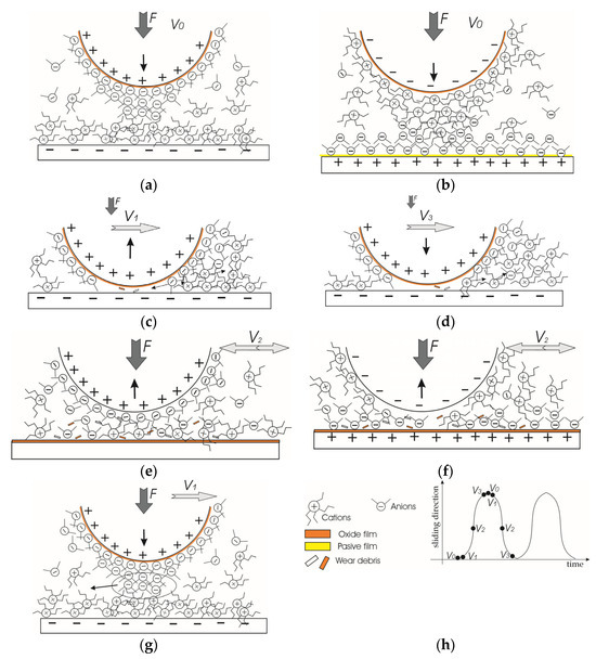
Figure 12.
The schematic representation of molecular layer distribution in ionic liquid lubricant be-tween interacting surfaces: (a) ball (+); (b) ball (−); (c) ball (+) start of motion from an end of wear trace; (d) ball (+) end of motion at the end of wear trace; (e) ball (+) maximum speed at the middle of wear trace; (f) ball (−) maximum speed at the middle of wear trace; (g) ball (+) very beginning of test; and (h) schematic of marking. ↑—vector of vertical displacement; V—speed of horizontal motion; F—load.
Applying a positive potential to the ball and a negative potential to the plate led to the formation of a thick cation-rich layer on the plate (Figure 12b). The P[6,6,6,14] cations can establish a dense, thick adsorbed layer that is difficult to compress or remove from the surface [11]. Furthermore, cations may rapidly reabsorb on the wear trace while the ball moves. At the same time, the [DCN] anion-rich layer forms on the ball surface. The anions have a stronger and faster interaction with the charged surface than the cations [19]. The electric field strength will not be uniform at the periphery of the sphere. It will be stronger at the tip of the sphere [36]. Taking this into account and the crowding phenomenon, it is likely that the ion concentration (layer) will be largest at the tip of the sphere. Moreover, the interacting ball tip surface is always in contact with the plate surface, preventing the reabsorption of anions. Therefore, the ability of the anion layer to regenerate quickly is an advantage. Another factor not favourable to lubricity was preventing oxide film formation on the negatively charged plate surface. Therefore, the wear scar on the steel plate was smoother than in the no-voltage case even though the wear was slightly higher (Table 1).
Considering the shape of the wear trace on the plate, it differs from the other two cases, having a broader and deeper appearance at the ends of the wear trace, as shown in Figure 5. Most likely, during those short periods when the ball speed changes, at the ends of the wear trace, wear debris is produced in the form of microabrasives (Figure 12c,d). These abrasives further act as a gentle polishing media. At a higher speed, the direct contact between interacting surfaces and abrasives is significantly reduced (Figure 12e). The stable cationic layer greatly influences this because it separates the friction surfaces [7,8]. As the steel ball translates over the plate, an ongoing boundary to mixed lubrication creates a unique wear profile, which is complicated by tribochemical reactions that may result in a “bone-shaped” wear trace [37,38].
The adsorbed layers change when the potentials are reversed to ball (−). In this case, P[6,6,6,14] cations adsorbed onto the ball can maintain lubricity for a period. Still, eventually, the molecules will be removed, making it difficult to readsorb when the ball tip remains in contact all the time. Although the [DCN] anions adsorb onto the positively charged plate surface with the ability to reabsorb, the layer is thin and can be easily rubbed from the surface. However, we would assume that if the crowding effect occurs, there is practically no cationic layer on the tip of the ball, as it has a weaker adhesion to the surface exposed to the load. Longer cation chains lead to higher friction, at low film thicknesses, and greater shear thinning, as the ball rubs the anionic layer more [16]. A thinner layer of anions separates the friction surfaces less, which is why the wear of the surfaces is more intense in this case. A greater manifestation of adhesive wear is indicated by the grooves formed on the ball’s wear scar (Figure 5) and adhesive pits on the plate (Figure 7). Moreover, the positively charged plate surface tends to oxidise. Due to the direct asperity contacts, the delamination of the oxide layer occurs, forming wear debris, which results in three-body wear and further abrasion.
Comparing these two cases, a layer formed by cations can better separate friction surfaces and more stably maintain a thicker and stronger protective film, especially if the crowding effect occurs. Large cation molecules and strong adhesion of the anion layer on the ball lift the ball in the very first seconds after it starts moving, although part of the formed anion layer is removed from the bead tip (Figure 12g). Possibly the ball pushes them away and stays in contact with the plate at speeds close to V0. This also can be interpreted by the graph (Figure 9a)—the contact resistance is minimal at the very first 2 s (part of the anion layer is scraped off, the distance to the plate decreases) and then raises, as seen in the character of the contact resistance curve in Figure 10. However, in the long run, the cation layer, being denser and stronger due to the crowding effect, and, in addition, not being in constant contact with the ball, having better conditions for renewal, separates the friction surfaces from each other and holds them quite stable.
On the other hand, a thin layer of anions having good adhesion and a thick initial layer of cations on the ball lifts the ball faster, and the mECR rises in the very first moments (Figure 9b). In the long run, the anion layer, being thinner, is unstable and poorly separates the surfaces. Since the cation layer is closely scraped off the ball tip, the negative charge of the ball can directly and destructively affect the negatively charged anion layer. The three-body friction factor increases, and the friction surfaces come into greater contact, so the mECR decreases (Figure 11), and wear rate increases (Figure 5, Ball (−)).
In the tribo-test, the mixed molecular layers were formed when no voltage was applied (Figure 12a). COF variation shows that the initially raised friction later decreases and stabilises. Based on the previously discussed information, it was speculated that the mixed and poorly oriented molecular layers resulted in initially higher friction and higher contact temperature, which initiated tribo-reactions. As a result, the cation and anion containing tribo-film was built [9,39]. The worn surfaces contained elements from both cations and anions (Table 2). This layer resulted in easy sharing between surfaces and negligible wear.
5. Conclusions
This study investigated the lubricity of phosphonium ionic liquid in reciprocating steel–steel sliding contact under an applied external electric potential when interacting surfaces possess opposite charge. The following conclusions can be drawn from this investigation:
- Trihexyltetradecylphosphonium dicyanamide ionic liquid exhibits optimal lubricity in the absence of any external electric potential. Applying a relatively small electric potential reduces its lubricity with the lowest performance observed when a negative potential is applied to the ball.
- The applied electric potential caused polar molecules to order and crowd near the oppositely charged interacting surfaces. The larger cation molecules adsorbed onto the plate, with the possibility of readsorption, thereby improving lubrication conditions more effectively than small anions.
- Comparing the investigated polarity conditions in the reciprocation of oppositely charged surfaces, several differences can be highlighted: (i) the ball (−) test produced a significantly higher ECR at the onset of the tribo-test, which was attributed to the relatively thick cation layer on the ball tip; (ii) even though the ball (+) test disrupts the lubricity of trihexyltetradecylphosphonium dicyanamide ionic liquid, it represents all the tribo-test stages in the line with the variation of coefficient of friction; and (iii) the ball (−) polarity disturbs tribo-film formation, leading to much lower ECR at the steady-state regime.
- Further research is needed to evaluate how the IL structure and current density affect the tribological behaviour of electrified friction pairs. Moreover, the lubricity of IL-modified base oils is particularly important for practical applications.
Author Contributions
Conceptualization, R.K. and A.Ž.; methodology, R.K.; software, A.A.; validation, R.K., A.Ž. and A.A.; formal analysis, R.K. and A.Ž.; investigation, R.K., A.Ž. and A.A.; resources, R.K.; data curation, A.A.; writing—original draft preparation, R.K. and A.Ž.; writing—review and editing, R.K., A.Ž. and A.A.; visualisation, R.K., A.Ž. and A.A.; supervision, R.K.; project administration, R.K.; funding acquisition, R.K. All authors have read and agreed to the published version of the manuscript.
Funding
This research was funded by grant No. S-MIP-21-61 from the Research Council of Lithuania.
Data Availability Statement
The data presented in this study are available on request from the corresponding author.
Acknowledgments
The authors thank the Research and Arts Unit of the Research and Innovation Department of Vytautas Magnus University for the opportunity to purchase the ionic liquids necessary for the study from the 2024 Competition for Research (Arts) Projects funding of Clusters.
Conflicts of Interest
The authors declare no conflicts of interest.
Abbreviations
The following abbreviations are used in this manuscript:
| ECR | electrical contact resistance |
| aECR | average electrical contact resistance |
| mECR | measured electrical contact resistance |
| P[6,6,6,14] | trihexyltetradecylphosphoniumcation |
| [DCN] | dicyanamide anion |
References
- Munavirov, B.; Black, J.J.; Shah, F.U.; Leckner, J.; Rutland, M.W.; Harper, J.B.; Glavatskih, S. The effect of anion architecture on the lubrication chemistry of phosphonium orthoborate ionic liquids. Sci. Rep. 2021, 11, 24021. [Google Scholar] [CrossRef]
- Yadav, G.D.; Tekale, S.P. Selective O-Alkylation of 2-Naphthol using Phosphonium-Based Ionic Liquid as the Phase Transfer Catalyst. Org. Process Res. Dev. 2010, 14, 722–727. [Google Scholar] [CrossRef]
- Stachowiak, G.W.; Batchelor, A.W.; Tribology, E. Engineering Tribology; Elsevier: Amsterdam, The Netherlands, 2013. [Google Scholar] [CrossRef]
- Otero, I.; López, E.R.; Reichelt, M.; Villanueva, M.; Salgado, J.; Fernández, J. Ionic Liquids Based on Phosphonium Cations As Neat Lubricants or Lubricant Additives for a Steel/Steel Contact. ACS Appl. Mater. Interfaces 2014, 6, 13115–13128. [Google Scholar] [CrossRef]
- Anand, M.; Hadfield, M.; Viesca, J.L.; Thomas, B.; González, R.; Cantrill, R.; Battez, A.H. Assessing boundary film forming behavior of phosphonium ionic liquids as engine lubricant additives. Lubricants 2016, 4, 17. [Google Scholar] [CrossRef]
- Liu, T.; Panwar, P.; Khajeh, A.; Rahman, M.H.; Menezes, P.L.; Martini, A. Review of Molecular Dynamics Simulations of Phosphonium Ionic Liquid Lubricants. Tribol. Lett. 2022, 70, 44. [Google Scholar] [CrossRef]
- Khan, A.; Sharma, O.P.; Khatri, O.P. Ionic Liquids-Based Aqueous Lubricants: Emulsion Stability to Enhancement of Surface Wettability and Tribological Properties. Ind. Eng. Chem. Res. 2021, 60, 333–342. [Google Scholar] [CrossRef]
- Kondo, Y.; Yagi, S.; Koyama, T.; Tsuboi, R.; Sasaki, S. Lubricity and corrosiveness of ionic liquids for steel-on-steel sliding contacts. Proc. Inst. Mech. Eng. Part J J. Eng. Tribol. 2012, 226, 991–1006. [Google Scholar] [CrossRef]
- Kawada, S.; Sasaki, S.; Miyatake, M. Effect of surrounding atmosphere on friction properties of hydrophobic and hydrophilic ionic liquids. Tribol. Online 2019, 14, 285–292. [Google Scholar] [CrossRef]
- Sweeney, J.; Hausen, F.; Hayes, R.; Webber, G.B.; Endres, F.; Rutland, M.W.; Bennewitz, R.; Atkin, R. Control of nanoscale friction on gold in an ionic liquid by a potential-dependent ionic lubricant layer. Phys. Rev. Lett. 2012, 109, 155502. [Google Scholar] [CrossRef]
- Zhang, Y.; Rutland, M.W.; Luo, J.; Atkin, R.; Li, H. Potential-Dependent Superlubricity of Ionic Liquids on a Graphite Surface. J. Phys. Chem. C 2021, 125, 3940–3947. [Google Scholar] [CrossRef]
- Bazant, M.Z.; Storey, B.D.; Kornyshev, A.A. Double layer in ionic liquids: Overscreening versus crowding. Phys. Rev. Lett. 2011, 106, 046102. [Google Scholar] [CrossRef]
- Fedorov, M.V.; Kornyshev, A.A. Ionic liquids at electrified interfaces. Chem. Rev. 2014, 114, 2978–3036. [Google Scholar] [CrossRef]
- Hjalmarsson, N.; Wallinder, D.; Glavatskih, S.; Atkin, R.; Aastrup, T.; Rutland, M.W. Weighing the surface charge of an ionic liquid. Nanoscale 2015, 7, 16039–16045. [Google Scholar] [CrossRef] [PubMed]
- Zhu, J.; Mao, X. Elucidating ionic liquids-mediated electrochemical interfaces for energy storage and electrocatalysis. Mater Today Energy 2025, 51, 101908. [Google Scholar] [CrossRef]
- Zhang, X.; Han, M.; Espinosa-Marzal, R.M. Thin-Film Rheology and Tribology of Imidazolium Ionic Liquids. ACS Appl Mater Interfaces 2023, 15, 45485–45497. [Google Scholar] [CrossRef] [PubMed]
- Seed, C.M.; Acharya, B.; Krim, J. QCM Study of Tribotronic Control in Ionic Liquids and Nanoparticle Suspensions. Tribol. Lett. 2021, 69, 83. [Google Scholar] [CrossRef]
- Reddy, A.B.; Pilkington, G.A.; Rutland, M.W.; Glavatskih, S. Tribotronic control of an ionic boundary layer in operando extends the limits of lubrication. Sci. Rep. 2022, 12, 20479. [Google Scholar] [CrossRef]
- Gatti, F.; Amann, T.; Kailer, A.; Baltes, N.; Rühe, J.; Gumbsch, P. Towards programmable friction: Control of lubrication with ionic liquid mixtures by automated electrical regulation. Sci. Rep. 2020, 10, 17634. [Google Scholar] [CrossRef]
- Blesic, M.; Lopes, J.N.C.; Gomes, M.F.C.; Rebelo, L.P.N. Solubility of alkanes, alkanols and their fluorinated counterparts in tetraalkylphosphonium ionic liquids. Phys. Chem. Chem. Phys. 2010, 12, 9685–9692. [Google Scholar] [CrossRef]
- Naveed, T.; Zahid, R.; Mufti, R.A.; Waqas, M.; Hanif, M.T. A review on tribological performance of ionic liquids as additives to bio lubricants. Proc. Inst. Mech. Eng. Part J J. Eng. Tribol. 2020, 235, 1782–1806. [Google Scholar] [CrossRef]
- Pereira, G.F.L.; Pereira, R.G.; Salanne, M.; Siqueira, L.J.A. Molecular Dynamics Simulations of Ether-Modified Phosphonium Ionic Liquid Confined in between Planar and Porous Graphene Electrode Models. J. Phys. Chem. C 2019, 123, 10816–10825. [Google Scholar] [CrossRef]
- Fedorov, M.V.; Kornyshev, A.A. Ionic Liquid Near a Charged Wall: Structure and Capacitance of Electrical Double Layer. J. Phys. Chem. B 2008, 112, 11868–11872. [Google Scholar] [CrossRef] [PubMed]
- Lockett, V.; Horne, M.; Sedev, R.; Rodopoulos, T.; Ralston, J. Differential capacitance of the double layer at the electrode/ionic liquids interface. Phys. Chem. Chem. Phys. 2010, 12, 12499–12512. [Google Scholar] [CrossRef] [PubMed]
- Bambam, A.K.; Alok, A.; Rajak, A.; Gajrani, K.K. Tribological performance of phosphonium-based halogen-free ionic liquids as lubricant additives. Proc. Inst. Mech. Eng. Part J 2022, 237, 881–893. [Google Scholar] [CrossRef]
- Shah, F.U.; Glavatskih, S.; MacFarlane, D.R.; Somers, A.; Forsyth, M.; Antzutkin, O.N. Novel halogen-free chelated orthoborate–phosphonium ionic liquids: Synthesis and tribophysical properties. Phys. Chem. Chem. Phys. 2011, 13, 12865–12873. [Google Scholar] [CrossRef]
- Sheehan, A.; Jurado, L.A.; Ramakrishna, S.N.; Arcifa, A.; Rossi, A.; Spencer, N.D.; Espinosa-Marzal, R.M. Layering of ionic liquids on rough surfaces. Nanoscale 2016, 8, 4094–4106. [Google Scholar] [CrossRef]
- Kornyshev, A.A. Double-layer in ionic liquids: Paradigm change? J. Phys. Chem. B 2007, 111, 5545–5557. [Google Scholar] [CrossRef]
- Spikes, H.A. Triboelectrochemistry: Influence of Applied Electrical Potentials on Friction and Wear of Lubricated Contacts. Tribol. Lett. 2020, 68, 90. [Google Scholar] [CrossRef]
- Yamaguchi, E.S.; Ryason, P.R.; Yeh, S.W.; Hansen, T.P. Boundary film formation by zndtps and detergents using ecr. Tribol. Trans. 1998, 41, 262–272. [Google Scholar] [CrossRef]
- Kreivaitis, R.; Andriušis, A.; Treinytė, J.; Kupčinskas, A.; Jankauskas, V. Investigation of the Lubricating Conditions in a Reciprocating Sliding Tribotest with Applied Electric Voltage. Lubricants 2024, 12, 104. [Google Scholar] [CrossRef]
- Glovnea, R.; Furtuna, M.; Nagata, Y.; Sugimura, J. Electrical Methods for the Evaluation of Lubrication in Elastohydrodynamic Contacts. Tribol. Online 2012, 7, 46–53. [Google Scholar] [CrossRef][Green Version]
- Yamamoto, Y.; Ono, B.; Ura, A. Effect of applied voltage on friction and wear characteristics in mixed lubrication. Lubr. Sci. 1996, 8, 199–207. [Google Scholar] [CrossRef]
- Yamamoto, Y.; Hirano, F. Scuffing resistance of phosphate esters II: Effect of applied voltage. Wear 1981, 66, 77–86. [Google Scholar] [CrossRef]
- Czeslaw, K. Importance of anionic reactive intermediates for lubricant component reactions with friction surfaces. Lubr. Sci. 2018, 6, 203–228. [Google Scholar] [CrossRef]
- Liang, F.; Wang, F.; Chen, S.; Sun, Q.; Zhong, L. Surface charge accumulation of post insulator: Dominant charge transition under different conditions. High Volt. 2023, 8, 1225–1233. [Google Scholar] [CrossRef]
- Poulia, A.; Georgatis, E.; Lekatou, A.; Karantzalis, A. Dry-Sliding Wear Response of MoTaWNbV High Entropy Alloy. Adv. Eng. Mater. 2017, 19, 1600535. [Google Scholar] [CrossRef]
- Huang, M.; Yang, B.; Rong, Y.; Zhao, L.; Xiao, S. Study on Friction and Wear Properties of Copper-Impregnated Carbon Slide Plate Under Different Humidity Conditions. Tribol. Trans. 2023, 66, 953–964. [Google Scholar] [CrossRef]
- Kawada, S.; Sasaki, S.; Miyatake, M. In-situ observation of tribo-decomposition behavior of ionic liquids composed of phosphonium-cation and cyano-anion using quadrupole mass spectrometer. Tribol. Int. 2021, 153, 106547. [Google Scholar] [CrossRef]
Disclaimer/Publisher’s Note: The statements, opinions and data contained in all publications are solely those of the individual author(s) and contributor(s) and not of MDPI and/or the editor(s). MDPI and/or the editor(s) disclaim responsibility for any injury to people or property resulting from any ideas, methods, instructions or products referred to in the content. |
© 2025 by the authors. Licensee MDPI, Basel, Switzerland. This article is an open access article distributed under the terms and conditions of the Creative Commons Attribution (CC BY) license (https://creativecommons.org/licenses/by/4.0/).