Dynamic Characteristics of ‘Floating’ Valve Plate for Internal Curve Hydraulic Motor

 ,
,
Abstract
1. Introduction
2. Mathematical Modelling
2.1. Mathematical Modelling of the Pressing Force on the VP
2.1.1. VP Balance Chamber Pressing Force
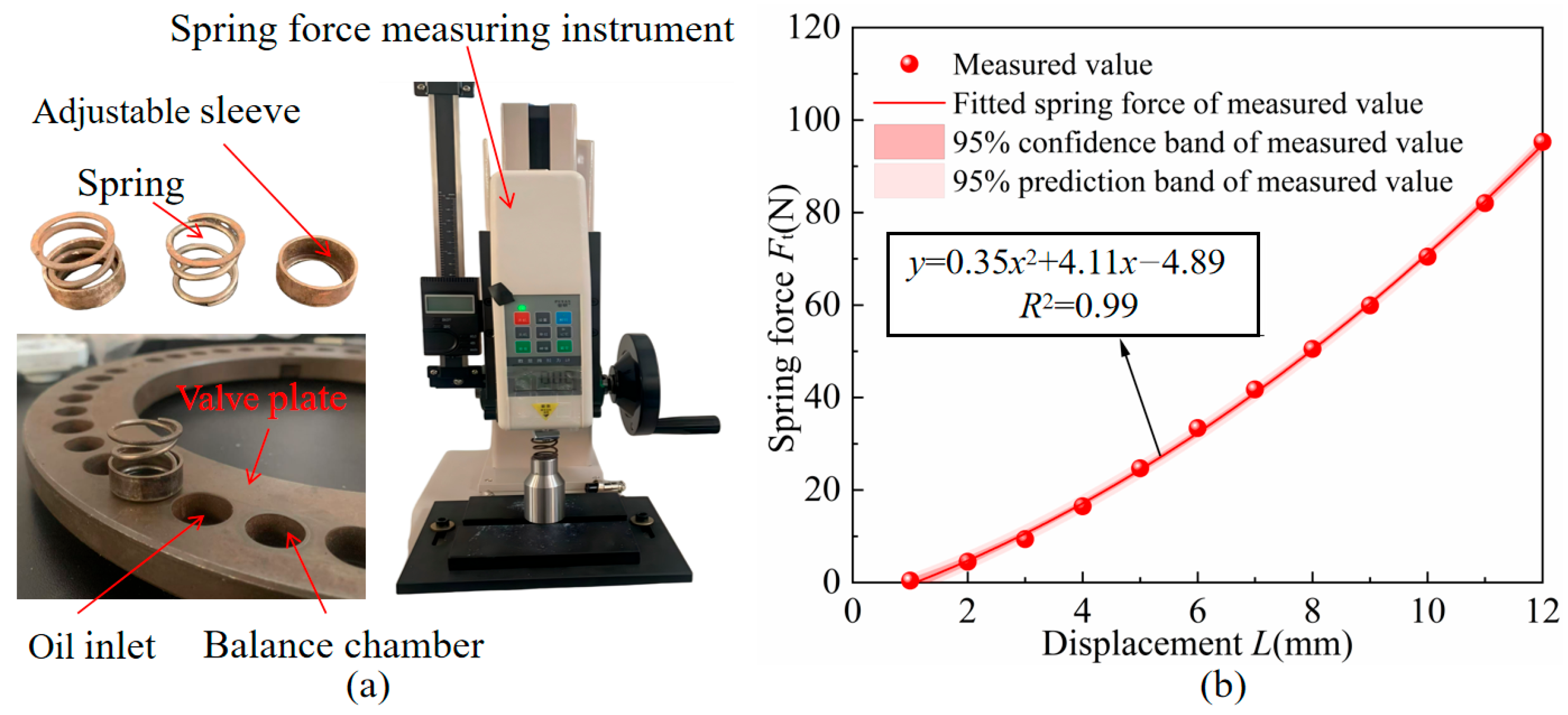
2.1.2. Telescopic Sleeve Spring Pressing Force
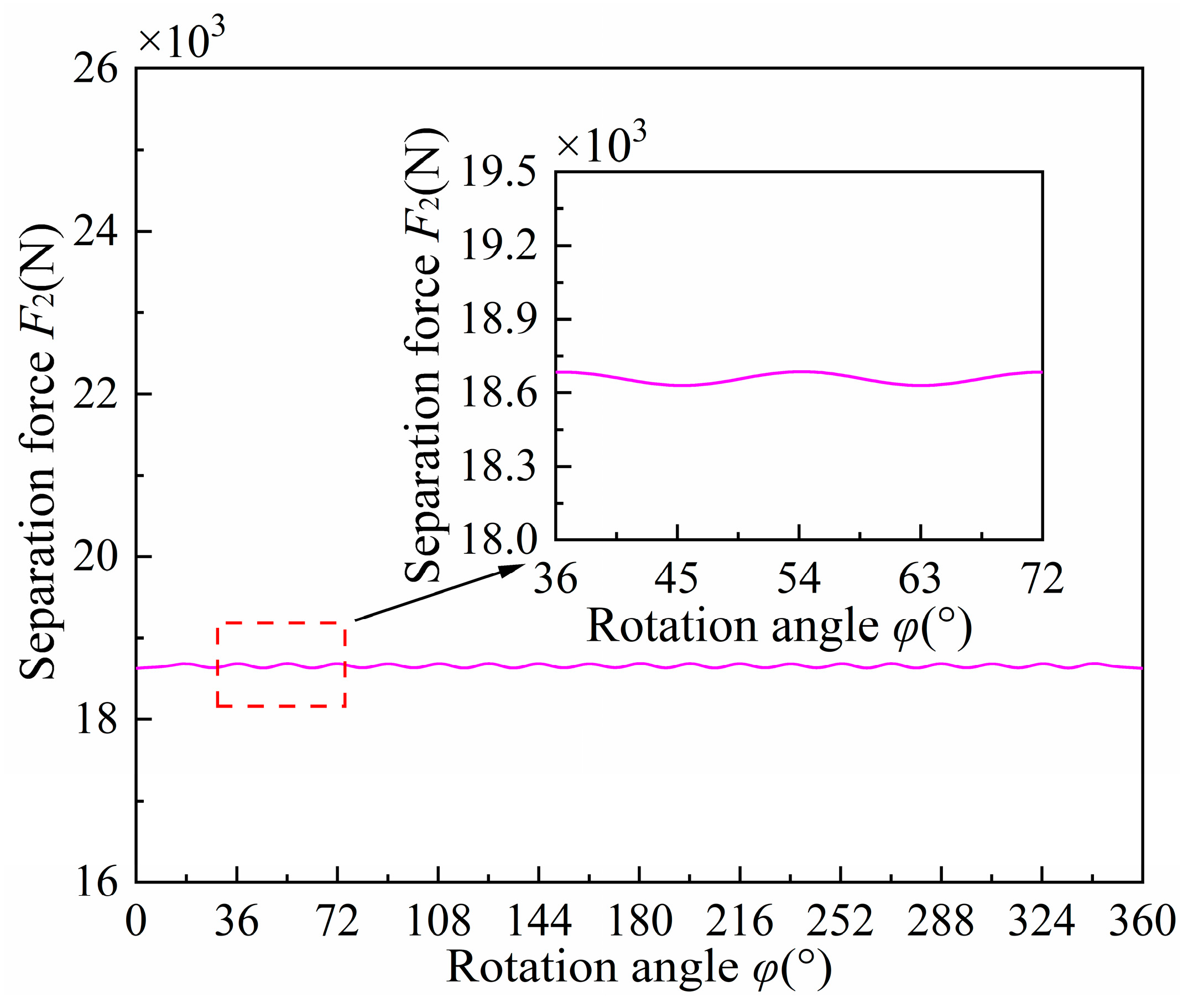
2.2. Mathematical Modelling of the Separation Force of VP
2.2.1. Bearing Force Generated by Squeezing the Oil Film on the VP
2.2.2. Separation Force of the Oil Film on the VP
2.2.3. Thrust of Hydraulic Power on the VP
2.3. Mathematical Modelling of the Micro-Motion of the VP
2.3.1. Force Analysis of VP
2.3.2. Equation of Dynamic Characteristics of the VP
2.3.3. Dynamic Thickness Equation for the Oil Film of the VPP
2.3.4. Equation for the Surplus Pressing Force of the VP
3. Simulation and Testing
3.1. Fluid Domain Simulation of ICHM
3.1.1. Computational Domain Modelling of Fluids in ICHM
3.1.2. Fluid Modelling Simulation of ICHM
3.1.3. Validation of Numerical Mesh Grid Independence in the Fluid Domain of the Balance Chamber
3.1.4. Verification of Simulation Time-Step Independence in the Fluid Domain of Balance Chamber
3.1.5. Balance Chamber Pressure Change Rule
3.2. Pressing Force of the VP
3.3. Telescopic Sleeve Pressing Force
3.4. Separation Force of Oil Film
3.5. Thrust of Hydraulic Power
3.6. Leakage Test of VPP
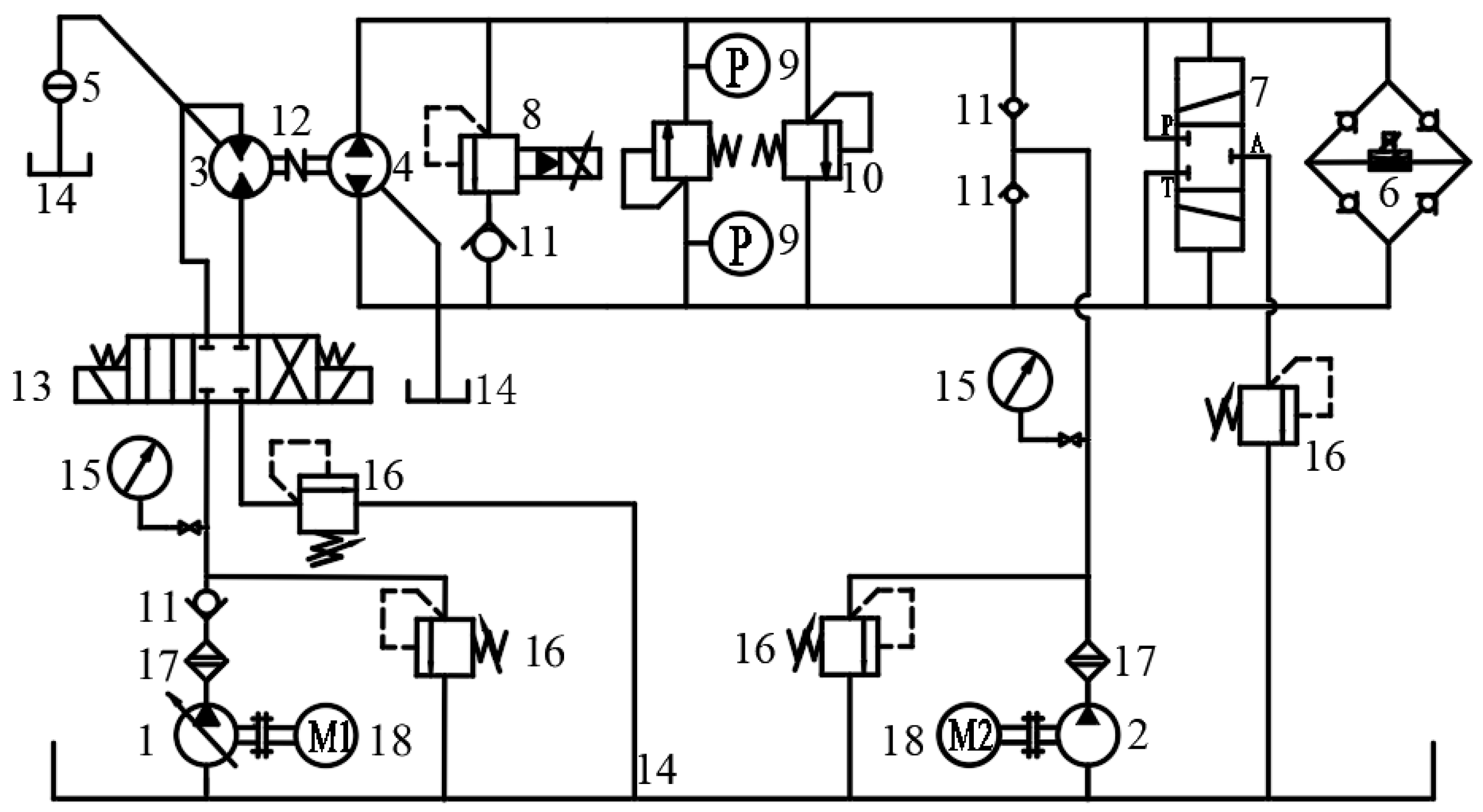
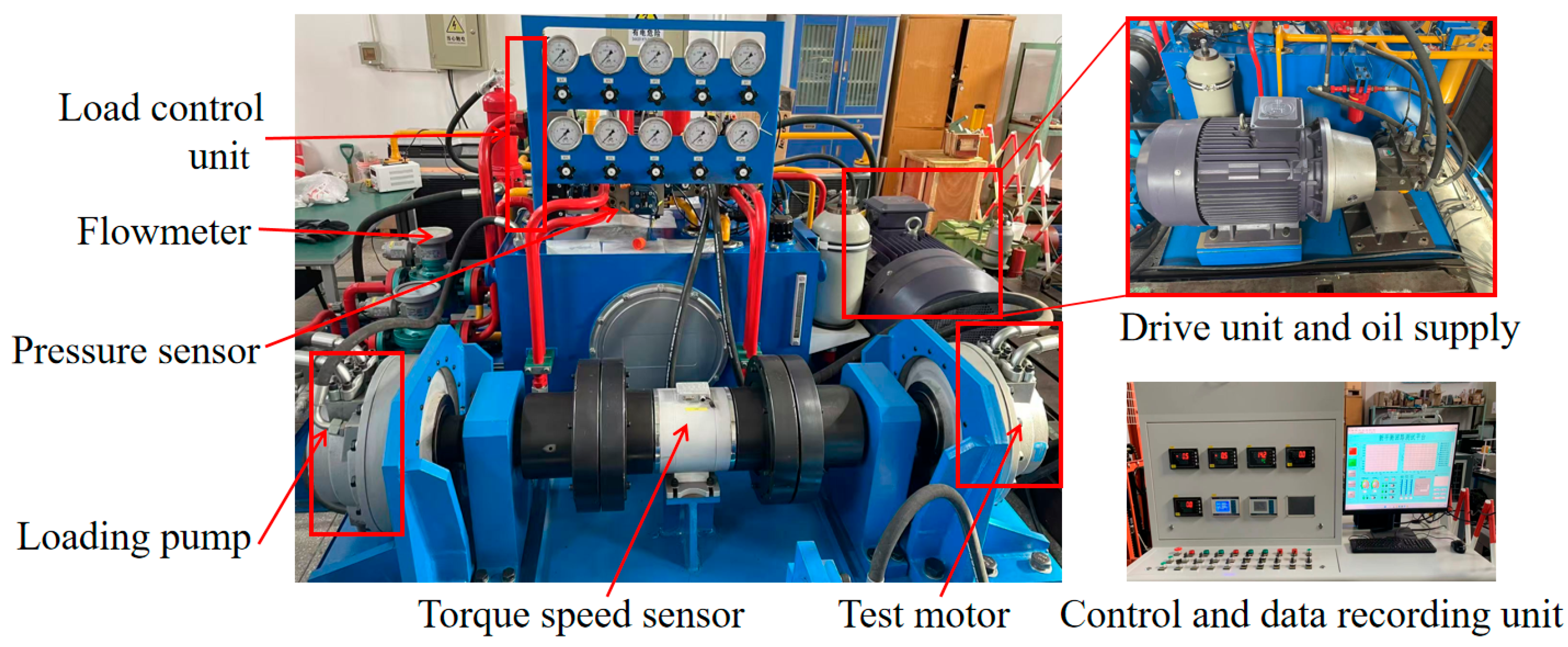
3.6.1. Experimental Setup
3.6.2. Test Results and Analysis
4. Results and Discussion
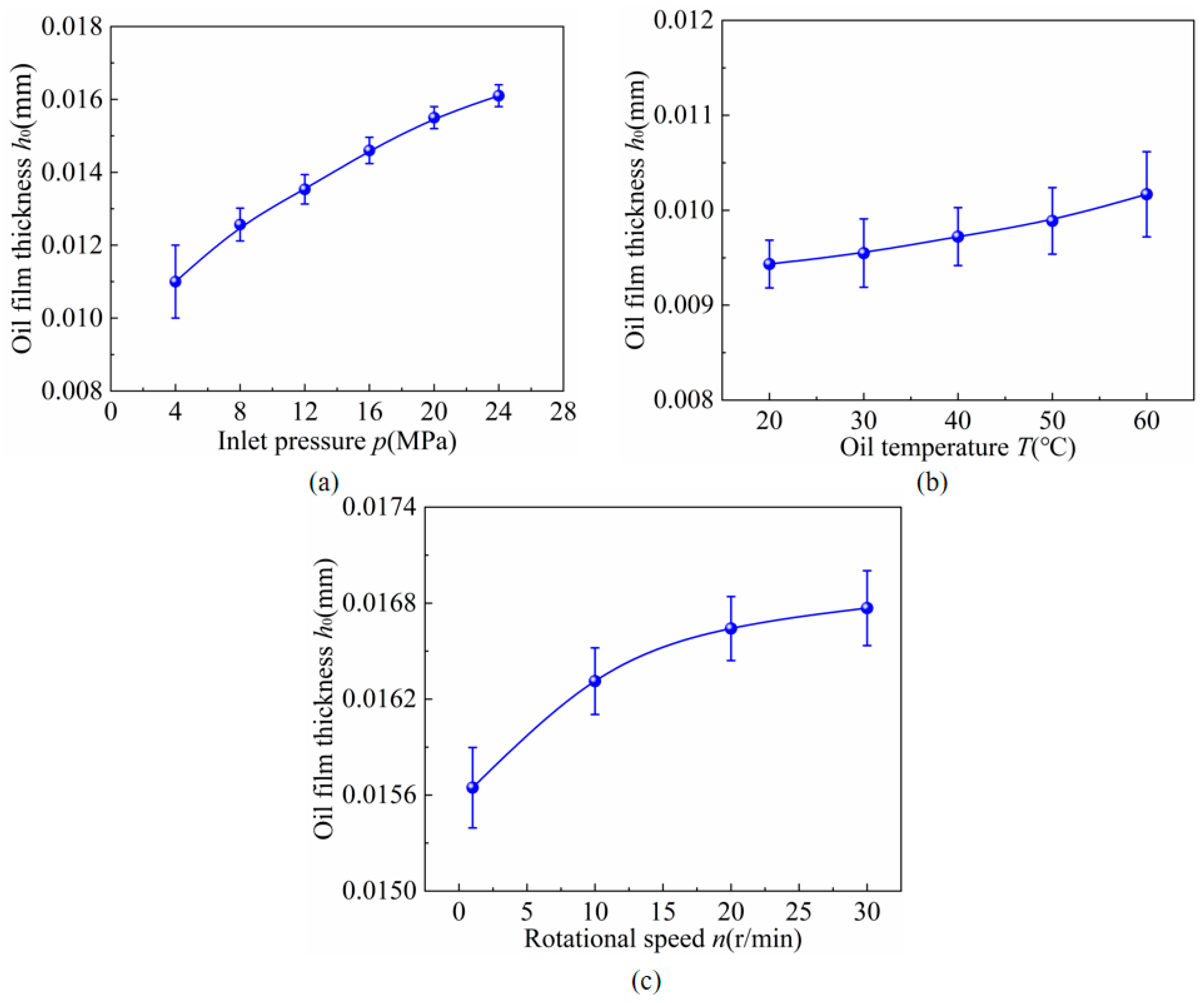
4.1. Thickness of the Oil Film of the VPP Under Different Working Conditions
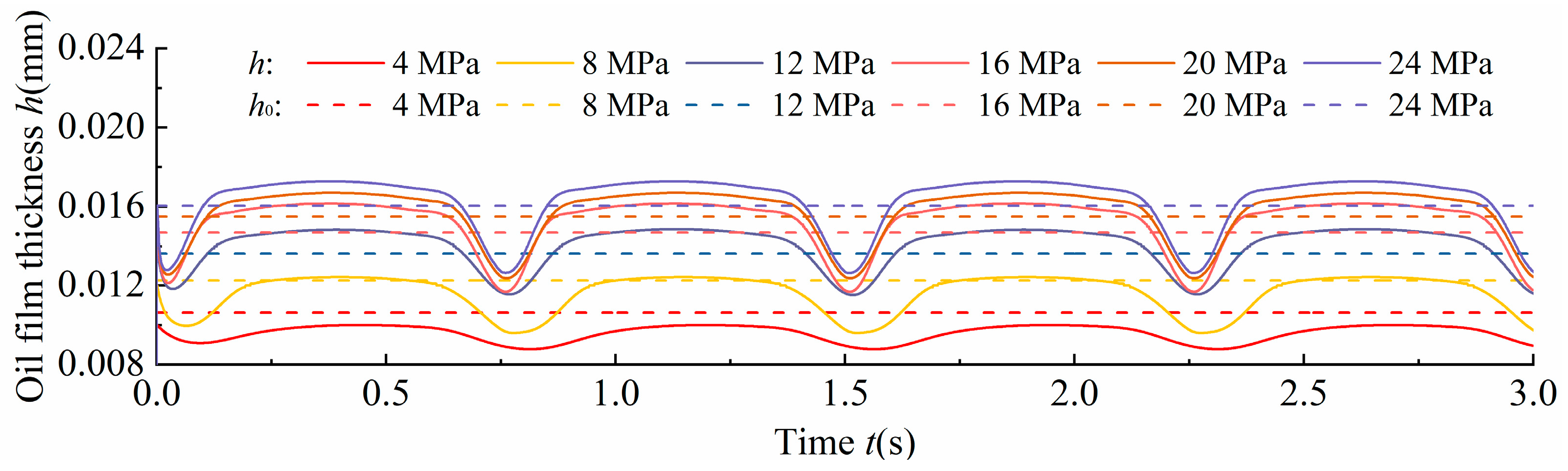
4.1.1. Oil Film Thickness at Different Inlet Pressures
4.1.2. Oil Film Thickness at Different Oil Temperatures
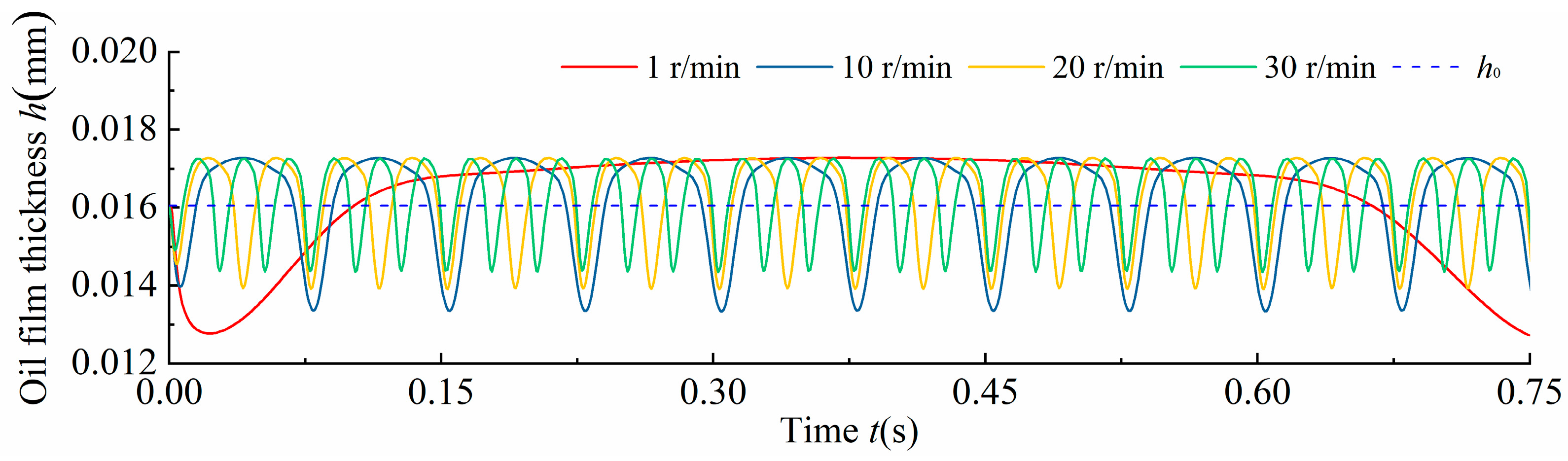
4.1.3. Oil Film Thickness at Different Rotational Speeds
4.2. Characteristics of the Maximum Displacement of the VP Under Different Working Conditions
4.2.1. Characteristics of the Maximum Displacement of the VP at Different Inlet Pressures
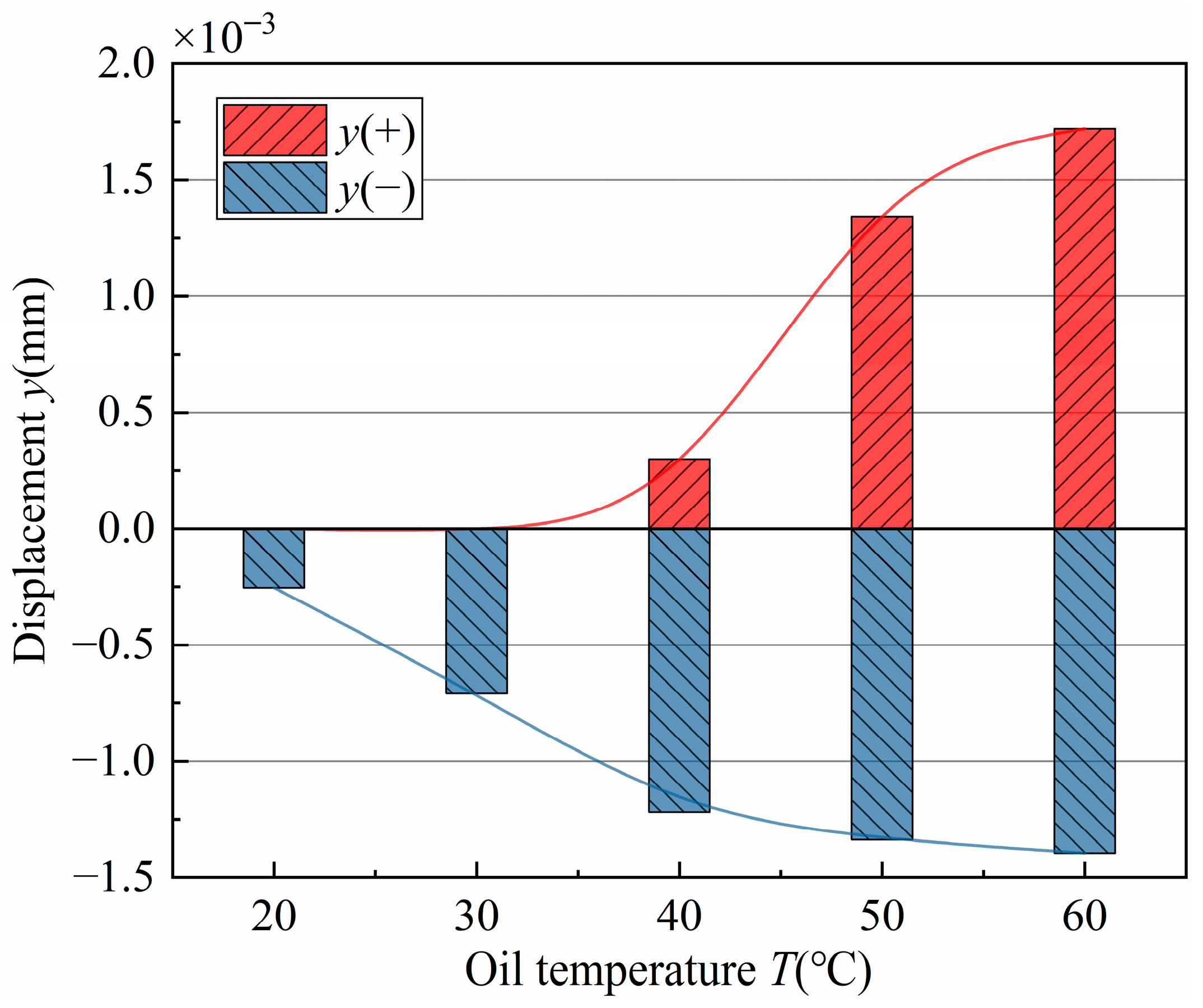
4.2.2. Characteristics of the Maximum Displacement of the VP at Different Oil Temperatures
4.2.3. Characteristics of the Maximum Displacement of the VP at Different Rotational Speeds
4.3. Surplus Pressing Force of ‘Floating’ VP for the ICHM
5. Conclusions
- As the inlet pressure increased, the thickness of the oil film on the valve plate pair increased. At the cylinder block rotational angle (periodic angle), the oil film is squeezed, and the oil film thickness is minimal. The higher the oil temperature, the larger the amplitude of the film thickness, and the more obvious the response of the valve plate to squeezing the film. With an increase in the rotational speed, the amplitude of the oil film thickness decreased, and the change in the oil film thickness was not obvious.
- When the inlet pressure is lower than 8 MPa, the valve plate squeezes the oil film; when the inlet pressure is more than 8 MPa, the thickness of the oil film of the valve plate pair increases. In the oil temperature range of 20–30 °C, the valve plate produced a squeezing effect on the oil film, resulting in a decrease in the thickness of the oil film. An increase in the rotational speed reduces the squeezing effect of the valve plate on the oil film, and the displacement of the valve plate is inversely proportional to the rotational speed.
- When the inlet pressure was 8.7 MPa, the valve plate was in a hydrostatic balance support state. When the inlet pressure exceeded 8.7 MPa, the surplus pressing force of the valve plate was insufficient. When the inlet pressure was lower than 8.7 MPa, the surplus pressing force of the valve plate was excessive. The coefficient of the surplus pressing force of the valve plate decreased with increasing inlet pressure.
Author Contributions
Funding
Data Availability Statement
Conflicts of Interest
Nomenclature
| the flow through the area of the distribution window | |
| the support area of the sealing band along the inner edge of the valve plate | |
| the area of action of the pressure in the balance chamber | |
| the support area of the sealing band along the outer edge of the valve plate | |
| projected area of the force on the cylinder block bore | |
| the pressure envelope angle correction factor | |
| the viscous damping coefficient of the oil | |
| the diameter of the balance chamber outlet | |
| the diameter of the balance chamber inlet | |
| balance chambers pressing force | |
| telescopic sleeves pressing force | |
| oil film bearing force | |
| oil film separating force | |
| thrust force | |
| the combined force in the x and y directions | |
| valve plate pressing force | |
| the combined force of the oil film separation force | |
| the stiffness coefficient of the oil film | |
| oil film thickness | |
| initial oil film thickness | |
| the elasticity coefficient of the spring | |
| the pressing displacement of the spring | |
| the mass of the valve plate | |
| pressure in the piston chamber | |
| pressure in the balance chamber | |
| leakage of the valve plate pair | |
| the radius of the sealing band of the valve plate | |
| pressure envelope angle | |
| surplus pressing force coefficient | |
| internal curve hydraulic motor periodic angle | |
| action amplitude angle | |
| cylinder block rotation angle | |
| viscosity of the oil | |
| AP | valve plate |
| APP | valve plate pair |
| ICHM | internal curve hydraulic motor |
References
- An, G.; Wang, W.; Dong, H.; Liu, B.; Song, W.; Hu, Z. Parameter Optimization of Vibration Reduction Structure for Low-Speed, Multi-Acting Cam Ring Motor. Actuators 2023, 12, 388. [Google Scholar] [CrossRef]
- Li, Y.; Cui, X.; Zhang, J. A Study on Improving Friction and Wear Performance of Bearing Bush in Radial Piston Hydraulic Motor. Wear 2024, 546–547, 205317. [Google Scholar] [CrossRef]
- Dasgupta, K.; Mandal, S.K.; Pan, S. Dynamic Analysis of a Low Speed High Torque Hydrostatic Drive Using Steady-State Characteristics. Mech. Mach. Theory 2012, 52, 1–17. [Google Scholar] [CrossRef]
- Nilsson, D.; Prakash, B. Investigation into the Seizure of Hydraulic Motors. Tribol. Int. 2010, 43, 92–99. [Google Scholar] [CrossRef]
- Wang, Z.; Hu, S.; Ji, H.; Wang, Z.; Liang, W. Study on the Characteristics of Oil Film Load Capacity for Axial Piston Pump. Aust. J. Mech. Eng. 2020, 18, S140–S150. [Google Scholar] [CrossRef]
- Richardson, D.; Sadeghi, F.; Rateick, R.G.; Rowan, S. Experimental and Analytical Investigation of Floating Valve Plate Motion in an Axial Piston Pump. Tribol. Trans. 2017, 60, 537–547. [Google Scholar] [CrossRef]
- Ma, H.; Liu, W.; Wu, D.; Yang, B.; Xia, Y.; Xia, S. An In-Situ Measurement Approach for the Oil Film Characteristics of the Spherical Valve Plate Pair in Axial Piston Pumps. Measurement 2024, 226, 114113. [Google Scholar] [CrossRef]
- Yin, W.; Zhang, J.; Wang, X.; Zhang, Q.; Li, Y. Volumetric Efficiency Degradation Prediction of Axial Piston Pump Based on Friction and Wear Test. Heliyon 2024, 10, e37334. [Google Scholar] [CrossRef] [PubMed]
- Liu, J.; Meng, S.; Zhou, X.; Gu, L. A Hydraulic Axial Piston Pump Fault Diagnosis Based on Instantaneous Angular Speed Under Non-Stationary Conditions. Lubricants 2023, 11, 406. [Google Scholar] [CrossRef]
- Li, Y.; Yin, W.; Liu, Y.; Wang, Z.; Han, X.; Zhang, J. Tribological Properties and Injection Molding of SCF-Reinforced PEEK/PTFE Composites for Radial Piston Hydraulic Motors. Compos. Part B Eng. 2025, 300, 112495. [Google Scholar] [CrossRef]
- Ye, S.; Zheng, C.; Bao, Y.; Miao, K.; Liu, H.; Zhao, S. Dynamic Characteristics Analyses of Coupled-Multibody Axial Piston Pump Model. Int. J. Mech. Sci. 2025, 299, 110379. [Google Scholar] [CrossRef]
- Yin, F.; Nie, S.; Ji, H.; Huang, Y. Non-Probabilistic Reliability Analysis and Design Optimization for Valve-Port Plate Pair of Seawater Hydraulic Pump for Underwater Apparatus. Ocean Eng. 2018, 163, 337–347. [Google Scholar] [CrossRef]
- Zhao, J.; Fu, Y.; Ma, J.; Fu, J.; Chao, Q.; Wang, Y. Review of Cylinder Block/Valve Plate Interface in Axial Piston Pumps: Theoretical Models, Experimental Investigations, and Optimal Design. Chin. J. Aeronaut. 2021, 34, 111–134. [Google Scholar] [CrossRef]
- Kumar, N.; Kumar, R.; Sarkar, B.K.; Maity, S. Condition Monitoring of Hydraulic Transmission System with Variable Displacement Axial Piston Pump and Fixed Displacement Motor. Mater. Today Proc. 2021, 46, 9758–9765. [Google Scholar] [CrossRef]
- Zhang, X.; Wu, H.; Chen, C.; Wang, D.; Li, S. Oil Film Lubrication State Analysis of Piston Pair in Piston Pump Based on Coupling Characteristics of the Fluid Thermal Structure. Eng. Fail. Anal. 2022, 140, 106521. [Google Scholar] [CrossRef]
- Zhang, Y.; Ma, Z.; Yin, F.; Nie, S.; Ji, H.; Luo, H. Numerical Investigation and Optimization of Valve Plate/Port Plate Interface of Integrated Pump-Motor Unit for SWRO Desalination System. Desalination 2025, 613, 119003. [Google Scholar] [CrossRef]
- Ma, W.; Yang, G.; Cao, W.; Bai, G.; Cao, C.; Song, S. Study on the Leakage Mechanism of the Valve Plate Pair of Internal Curve Hydraulic Motor. Adv. Mech. Eng. 2025, 17, 16878132251346850. [Google Scholar] [CrossRef]
- Li, C.; Jiang, T.; Liu, C.; Xu, H.; Shi, G. Investigation of the Leakage in the Flow Distribution Pair of Radial Piston Hydraulic Motors through CFD Analysis and Experiments. Flow Meas. Instrum. 2024, 96, 102555. [Google Scholar] [CrossRef]
- Ma, W.; Yang, G.; Cao, W.; Bai, G.; Cao, C.; Song, S. Modeling and Analysis of Internal Leakage Characteristics of the Internal Curve Motor by a CFD-Based Method. Processes 2024, 12, 2835. [Google Scholar] [CrossRef]
- Wang, Z.; Sun, L.; Han, B.; Wang, X.; Ge, Z. Study on the Thermohydrodynamic Friction Characteristics of Surface-Textured Valve Plate of Axial Piston Pumps. Micromachines 2022, 13, 1891. [Google Scholar] [CrossRef] [PubMed]
- Xia, S.; Huang, C.; Ye, S.; Jiao, W.; Xia, Y.; Zhu, Z. Study on the Running-in Tribological Performance and Mechanism of the Valve Plate with Surface Texture for Axial Piston Pumps. Wear 2025, 574–575, 206085. [Google Scholar] [CrossRef]
- Zhang, J.; Xu, H.; Chen, J.; Huang, W.; Huang, X.; Lyu, F.; Xu, B.; Pan, M.; Su, Q. Modeling and Analysis of the Tilt Behavior of the Cylinder Block in a High-Speed Axial Piston Pump. Mech. Mach. Theory 2022, 170, 104735. [Google Scholar] [CrossRef]
- Vivek, A.S.; Lalit, A.; Kesavaraj, M.; Prasanth, T.K.; Rajasekharan, R.; Kumar, S.; Raghu, N.; Verghis, S.G. Design Optimization of Valve Plate of a Bi-Directional Axial Piston Pump for Electro Hydrostatic Actuation Systems. Trans. Indian Natl. Acad. Eng. 2023, 8, 625–638. [Google Scholar] [CrossRef]
- Wang, T.; Yin, Y.; Wang, H.; Zhou, G.; Huang, W.; Liu, X. Numerical Study on Tribological Performance of the Floating Valve-Plate Pair in Axial Piston Pump. Adv. Mech. Eng. 2020, 12, 1687814020968320. [Google Scholar] [CrossRef]
- Wang, Z.; Hu, S.; Ji, H.; Wang, Z.; Liu, X. Analysis of Lubricating Characteristics of Valve Plate Pair of a Piston Pump. Tribol. Int. 2018, 126, 49–64. [Google Scholar] [CrossRef]
- Zheng, P.; Dou, P.; Dai, J.; Chang, S.; Jia, Y.; Wu, T.; Yu, M. Ultrasonic-Based Measurement of Oil Film Thickness in the Valve Plate Pair of an Aviation Fuel Piston Pump. Measurement 2025, 246, 116741. [Google Scholar] [CrossRef]
- Feuchtmüller, O.; Hörl, L.; Bauer, F. Oil Film Generation of a Hydraulic Rod Seal: An Experimental Study Using Ellipsometry. Tribol. Int. 2021, 162, 107102. [Google Scholar] [CrossRef]
- Pang, H.; Wu, D.; Deng, Y.; Cheng, Q.; Liu, Y. Effect of Working Medium on the Noise and Vibration Characteristics of Water Hydraulic Axial Piston Pump. Appl. Acoust. 2021, 183, 108277. [Google Scholar] [CrossRef]
- Banaszek, A. Identification of Optimal Efficiency Exploitation Conditions of Axial-Piston Hydraulic Motor A2FM Type Using Artificial Neural Network Algorithms. Procedia Comput. Sci. 2021, 192, 1532–1540. [Google Scholar] [CrossRef]


| Symbol | Value | Symbol | Value |
|---|---|---|---|
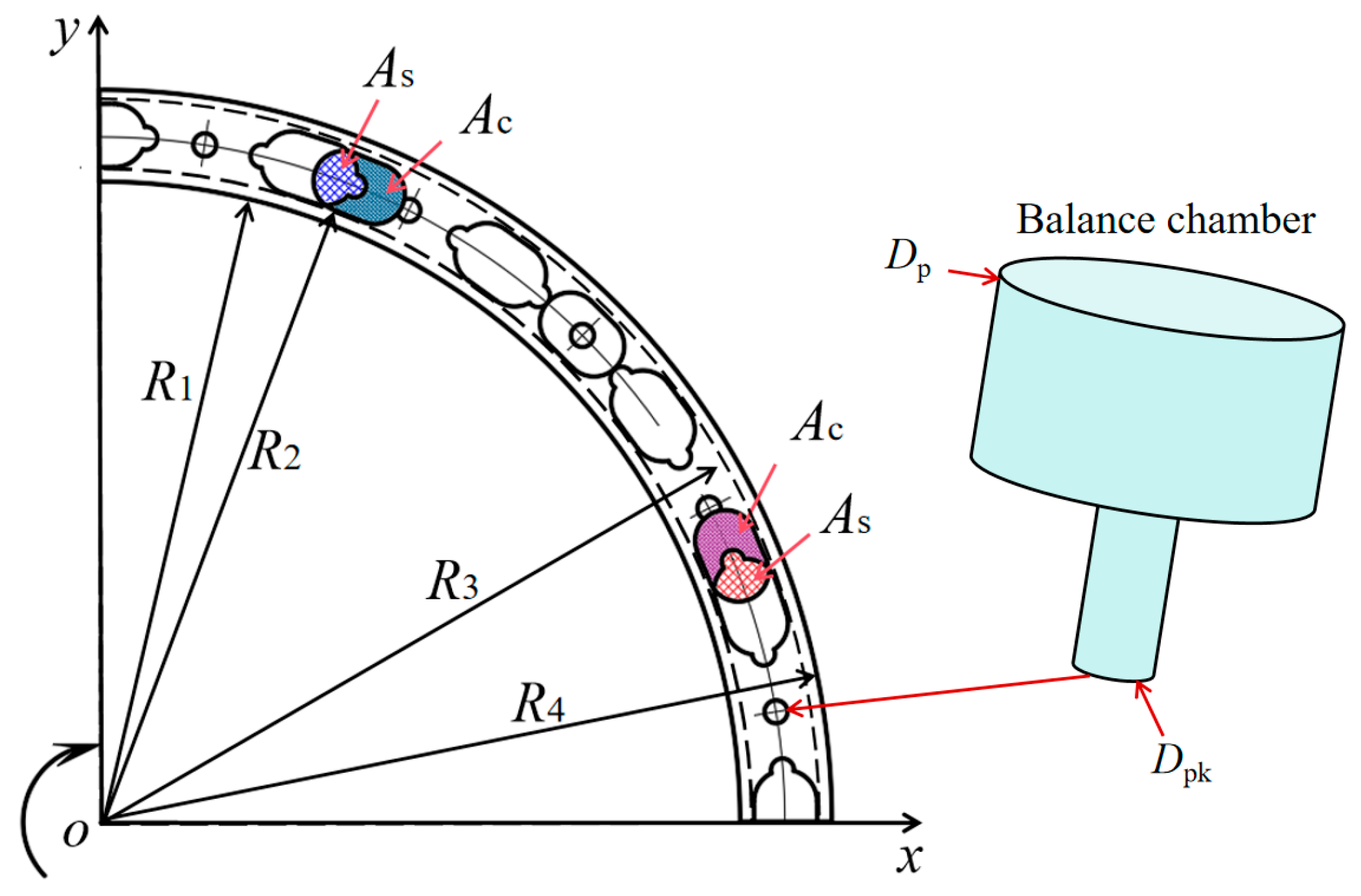
| R1 | 111.2 mm | Dpk | 3.8 mm |
| R2 | 113.3 mm | M | 3.4 kg |
| R3 | 125.5 mm | Cd | 51.5 MPa·S·m |
| R4 | 127.4 mm | μ | 0.043 Pa·S |
| Dp | 15.5 mm | C | 0.8 |
| Parameters | Value |
|---|---|
| Inlet pressure p | 10 MPa |
| Outlet pressure ps | 0.8 MPa |
| Rotation speed n | 30 r/min |
| Oil | LHM-46# Hydraulic Oil |
| Viscosity μ | 0.043 Pa·S |
| Turbulence model | Realizable k-ε |
| No. | Description | Parameters |
|---|---|---|
| 1 | Pressure sensor | PT5401, range 0–40 MPa, accuracy ± 0.05 |
| 2 | Flowmeter | FGR200, range 0.05–7 L/min, accuracy 0.5% |
| 3 | Torque speed sensor | ZH07, range 20,000 N·m, 0–500 r/min |
| 4 | Temperature sensor | SBWZ-2460, range −50–150 °C, accuracy 0.2% |
| 5 | Pressure gauge | Range 0–40 MPa, accuracy 0.025% |
| 6 | PLC | SIMATIC S7-1200, Siemens, Munich, Germany |
Disclaimer/Publisher’s Note: The statements, opinions and data contained in all publications are solely those of the individual author(s) and contributor(s) and not of MDPI and/or the editor(s). MDPI and/or the editor(s) disclaim responsibility for any injury to people or property resulting from any ideas, methods, instructions or products referred to in the content. |
© 2025 by the authors. Licensee MDPI, Basel, Switzerland. This article is an open access article distributed under the terms and conditions of the Creative Commons Attribution (CC BY) license (https://creativecommons.org/licenses/by/4.0/).
Share and Cite
Ma, W.; Yang, G.; Cao, W.; Yao, S.; Bai, G.; Cao, C.; Song, S. Dynamic Characteristics of ‘Floating’ Valve Plate for Internal Curve Hydraulic Motor. Lubricants 2025, 13, 307. https://doi.org/10.3390/lubricants13070307
Ma W, Yang G, Cao W, Yao S, Bai G, Cao C, Song S. Dynamic Characteristics of ‘Floating’ Valve Plate for Internal Curve Hydraulic Motor. Lubricants. 2025; 13(7):307. https://doi.org/10.3390/lubricants13070307
Chicago/Turabian StyleMa, Wei, Guolai Yang, Wenbin Cao, Shaohui Yao, Guixiang Bai, Chuanchuan Cao, and Shoupeng Song. 2025. "Dynamic Characteristics of ‘Floating’ Valve Plate for Internal Curve Hydraulic Motor" Lubricants 13, no. 7: 307. https://doi.org/10.3390/lubricants13070307
APA StyleMa, W., Yang, G., Cao, W., Yao, S., Bai, G., Cao, C., & Song, S. (2025). Dynamic Characteristics of ‘Floating’ Valve Plate for Internal Curve Hydraulic Motor. Lubricants, 13(7), 307. https://doi.org/10.3390/lubricants13070307