Abstract
CO2 displacement is a key technique that was examined through numerical methods in a 3D Hele–Shaw cell, with CO2 as the displacing phase and shear-thinning fluids as the displaced phase. Without interfacial tension effects, the displacement shows branching patterns forming two vertically symmetric fingers, regardless of whether the displacing fluid is air or CO2. Under CO2 displacement, viscous fingering propagates farther and achieves higher displacement efficiency than air. Compared with air displacement, the finger advancing distance increases by 0.0035 m, and the displacement efficiency is 15.2% higher than that of air displacement. Shear-thinning behavior significantly influences the process; stronger shear thinning enhances interfacial stability and suppresses fingering. As the power-law index n increases (reducing shear thinning), the fingering length extends. Variations in interfacial tension reveal it notably affects fingering initiation and velocity in CO2 displacement of non-Newtonian fluids, but has a weaker impact on fingering formation. Interfacial tension suppresses short-wavelength perturbations, critical to interface stability, jet breakup, and flows, informing applications like foam-assisted oil recovery and microfluidics.
1. Introduction
Viscous fingering [1,2,3] is a hydrodynamic phenomenon that typically occurs during the mutual displacement of two fluids with different viscosities, where the interface develops instability due to viscosity contrast, forming irregular finger-shaped invasion patterns. This phenomenon is widely observed in oil reservoir exploitation, environmental science, and microfluidics [4,5,6,7]. In petroleum extraction such as water flooding and carbon sequestration such as CO2 displacing subsurface fluids, fingering causes premature breakthrough of displacement fronts, forming inefficient flow channels that reduce resource recovery efficiency or storage stability [8,9,10]. Conversely, in microfluidic devices or multiphase reactors, intentionally induced viscous fingering can enhance mixing between fluids, particularly under low Reynolds numbers, by overcoming laminar flow constraints to reduce mixing time [11]. Therefore, investigating viscous fingering phenomena is both significant and necessary.
Regarding viscous fingering, Saffman and Taylor [12] first analyzed the influence of interfacial tension in flow fields on viscous fingering, demonstrating that surface tension plays a critical role in the evolution of flow patterns. Dong et al. [13] numerically investigated various factors influencing finger formation in two-dimensional (2D) channels, particularly emphasizing gravity’s impact, and found that gravity shortens breakthrough time under identical wetting conditions. He et al. [14] incorporated flow inertia in Hele–Shaw cells (HSCs) to establish nonlinear unsteady Darcy equations. Al-Housseiny et al. [15] theoretically studied viscous fingering in converging Hele–Shaw channels using Darcy’s law and Laplace’s equation. Kang et al. [16] simulated viscous fluid displacement in 2D channels, revealing that capillary number and wettability critically influence finger width and length. Shi et al. [17] conducted a numerical study on viscous fingering in channels using the lattice Boltzmann method, investigating the effects of capillary number, viscosity ratio, wettability, gravitational acceleration, three-dimensional (3D) geometry, and non-Newtonian rheological properties on finger development. The study revealed that fingering patterns generated in 3D geometries differ significantly from those in 2D geometries, with finger width being influenced by 3D geometric configurations and channel wall wettability. Currently, numerous scholars have conducted extensive experimental and theoretical studies [18,19,20,21,22] focusing on Newtonian fluids as the displaced phase, investigating the effects of fluid properties, flow inertia, channel geometry, permeability, and capillary pressure on viscous fingering.
Compared to Newtonian fluids, non-Newtonian fluid flow in HSCs has received less attention. However, it is noteworthy that fluid rheology plays a crucial role in the evolution of viscous fingering. In recent years, viscous fingering phenomena involving non-Newtonian fluids as the displaced phase have garnered significant scholarly interest. Azaiez et al. [23] investigated the linear interfacial stability of non-Newtonian fluids through numerical simulations using the finite difference method, revealing that shear-thinning fluids exhibit lower stability compared to Newtonian fluids. However, few studies have explored the impact of interfacial tension variations on viscous fingering when the displaced phase is non-Newtonian. Logvinov et al. [24] discovered that the fluid’s diffusion rate strongly depends on the power-law index n. Qin et al. [25] numerically simulated air displacement of non-Newtonian fluids with varying power-law indices, demonstrating that lower power-law indices yield shorter, thicker fingers and higher displacement efficiency. Mafei et al. [26] revealed the regulatory mechanism of depth gradients on interfacial stability by introducing minor depth gradients or modifying the geometric configuration of the HSC’s top plate, demonstrating the validity of utilizing depth gradients to control viscous fingering behavior in air displacing non-Newtonian fluids. Yang et al. [27] developed a pore-network model to simulate non-Newtonian fluid two-phase flow, identifying a transition mechanism from capillary to viscous fingering during displacement. Stronger shear-thinning effects in Ellis fluids facilitate the invasion of injected fluids into small-radius pore channels, thereby suppressing viscous fingering development, enhancing displacement efficiency, and significantly reducing transition zone scales. In studies on the displacement of non-Newtonian fluids, the impacts of non-Newtonian fluid properties, HSC configurations, and pore structures on viscous fingering have been examined. While most existing research employs conventional displacing phases such as water or air, investigations into CO2 displacement of non-Newtonian fluids remain scarce.
In summary, this study employs numerical simulations to analyze viscous fingering during CO2 displacement of shear-thinning fluids in a 3D HSC model. It investigates the effects of displacing fluid properties, shear-thinning fluid variations, and surface tension contrasts on viscous fingering dynamics.
2. Numerical Method
For the HSC system, the governing equation is usually expressed by the depth-average Darcy ‘s law, that is, the average velocity of each fluid along the depth is Formula (1):
where and are the phase j depth-averaged pressure and velocity vectors, respectively.
The velocity of the fluid is generally small, and the flow can be regarded as incompressible, so the continuity equation can be changed into
where is the velocity vector, and its motion equation is
In the formula, represents pressure, represents density, represents dynamic viscosity, represents a unit vector, represents time, and represents surface tension.
In this study, ANSYS Fluent (ANSYS 2022 R1) was used for numerical simulation. To capture the two-phase interface and describe the morphology of viscous fingering, the fluid volume method (VOF) based on the fixed Euler computational grid was used to track the free boundary. This method assumes that the fluid involved in the modeling flux is immiscible, but is included in the computational grid. The VOF method also uses a single coupled pressure equation and a single momentum equation for each dimension. In the modeled multiphase flow, it generates a shared velocity field, and the mass-weighted average mass and momentum transfer equations form the basis of modeling. These equations without phase–phase mass transfer are defined as Equations (4) and (5). The VOF method can effectively simulate the displacement, mixing, and interface stability (such as viscous fingering phenomenon) between different fluids, providing reliable interface evolution data for fields such as petroleum engineering and chemical engineering. In Singh’s research [28], he used this method to simulate the process of air displacement of glycine, as we also chose the VOF approach to simulate the flow of immiscible two-phase flow in this paper.
where the subscript refers to the gas (g) and liquid (l) phases such that . In addition, represents the velocity field of phase ; —volume fraction, —density, p—pressure, —viscosity, —gravity; and represents the surface tension.
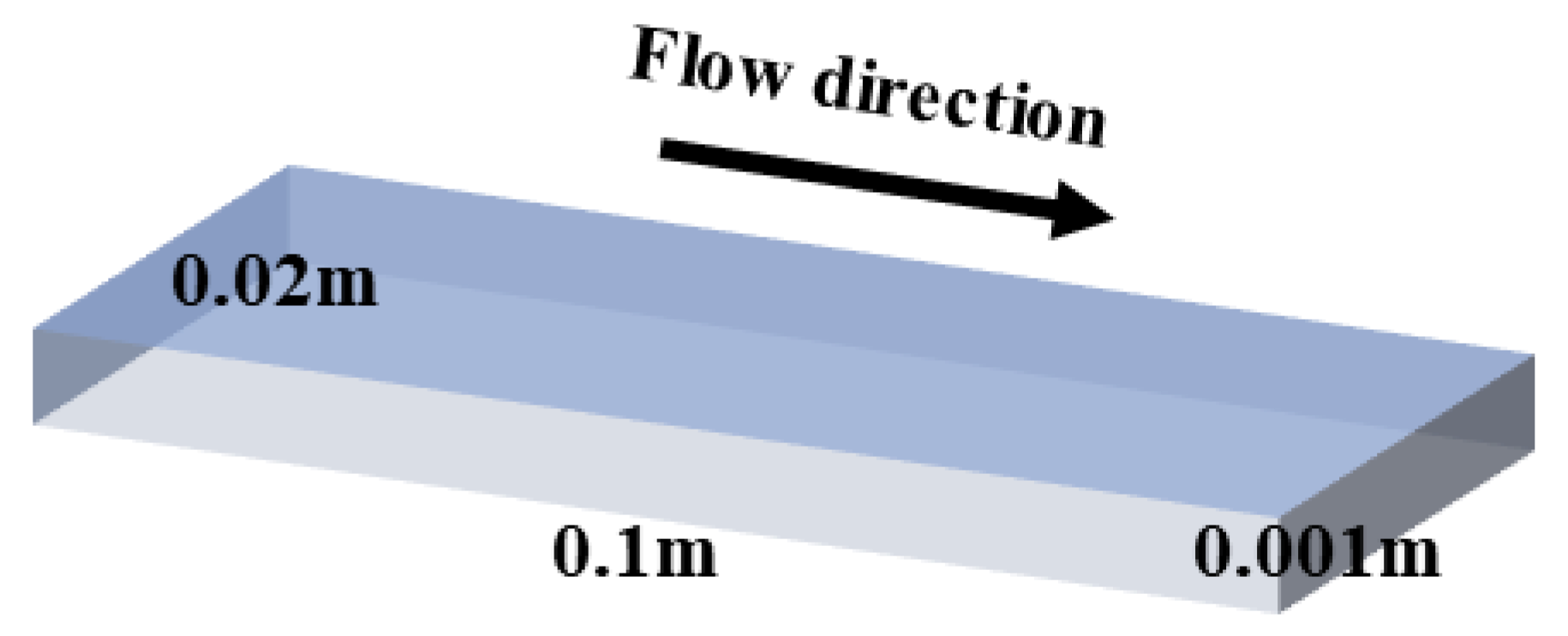
A Hele–Shaw Cell is an experimental device used to study fluid flow behavior between parallel plates. Its core structure consists of two narrowly spaced transparent parallel plates, typically with a gap (h) considerably smaller than the plate length and width (h ≪ L, W). Fluids injected between the plates enable the modeling and study of diverse physical phenomena by observing the resulting flow patterns. In this study, based on a 3D rectangular HSC, the length L and width W were 10 cm and 2 cm, respectively, and the distance h between the upper and lower plates was 1 mm, as shown in Figure 1. Throughout the simulations, a high-quality structured mesh with approximately 1.4 million grid cells was employed. The mesh was refined in the boundary layer regions, which is shown in Figure 2 (Left), to improve simulation accuracy. When there were more than 1.4 million elements in the meshed computational domain, the grid independent test, as shown in Figure 2 (Right), revealed that the velocity at the outflow did not depend on grid size. As a result, we took into account the 1.4-million-element count in the computational domain.

Figure 1.
Three-dimensional model of HSC.
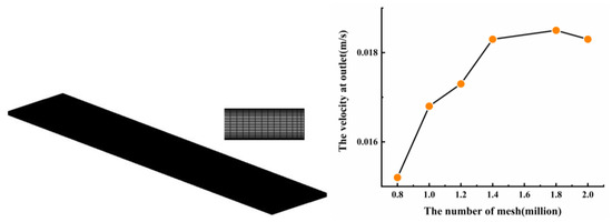
Figure 2.
Grid of computational domain (Left) and verification of mesh independence (Right).
In the setting of boundary conditions, CO2 displaces the non-Newtonian fluid at a constant speed of 0.02 m/s, and the outlet is the average static pressure outlet condition of the ambient atmosphere, that is, Prel = 0 Pa. The displaced phase is a non-Newtonian fluid, mainly considering the effect of shear thinning on viscous fingering. In the numerical simulation, a non-Newton power-law model of shear-thinning fluids is used. In this study, the focus is mainly on the flow of shear-thinning fluids during displacement, with n taking 0.2, 0.4, 0.6, and 0.8 for analysis.
where γ is the shear rate, and is the power law exponent. The fluid is classified into shear thickening for , shear thinning for , and the fluid recovers its Newtonian behavior at .
3. Comparative Analysis of Air and CO2 Displacing Non-Newtonian Fluids
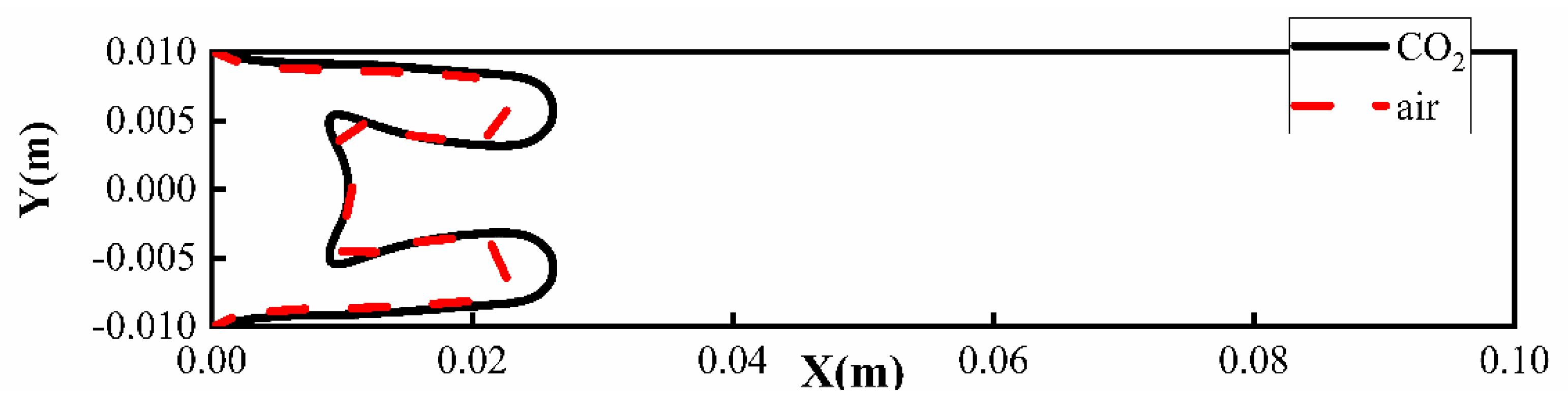
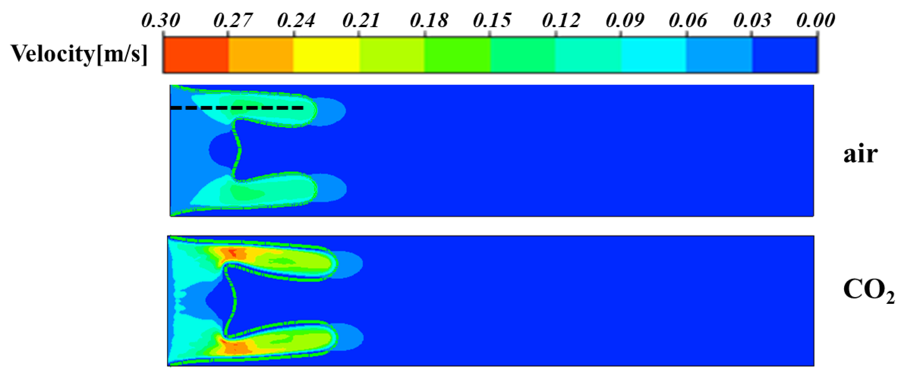
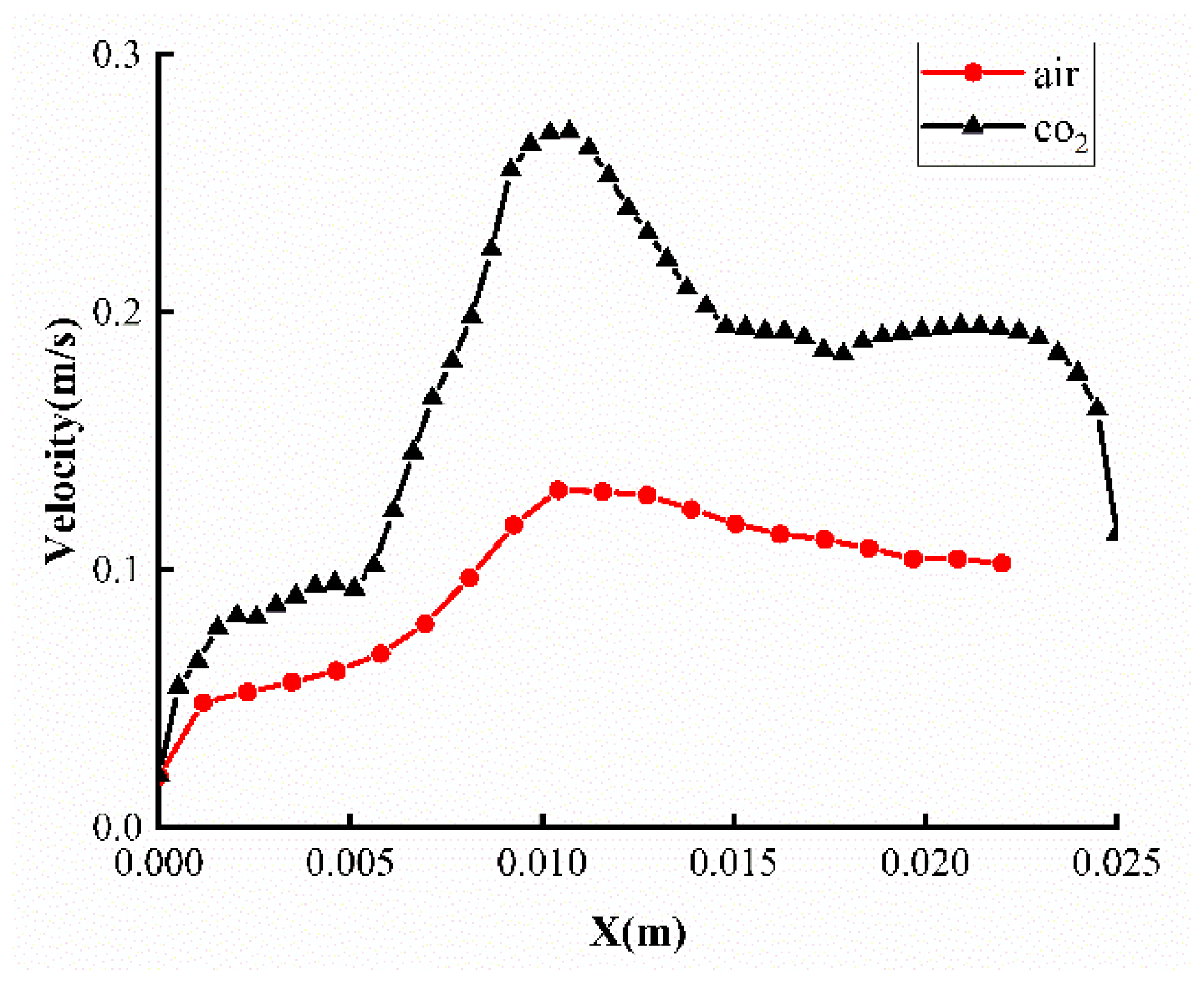
Gas displacement technologies such as air and CO2 are widely applied in petroleum engineering, environmental science, and chemical engineering for enhanced oil recovery and subsurface contaminant remediation. To investigate the influence of distinct displacing media on non-Newtonian fluid displacement under identical rheological conditions, air and CO2 were selected as displacing fluids for systematic comparative analysis. From the phase distribution depicted in Figure 3, it is evident that displacement with either air or CO2 as the displacing fluid induces branching phenomena, culminating in the formation of two vertically symmetric fingering structures. As demonstrated in Figure 4, CO2 displacement exhibits a significantly longer propagation length of viscous fingering and achieves higher displacement efficiency. Compared with air displacement, the finger advancing distance increases by 0.0035 m, and the displacement efficiency is 15.2% higher than that of air displacement. Furthermore, the fingering patterns under both CO2 and air displacement display symmetric distributions. Therefore, the velocity within a single finger was extracted for analysis, corresponding to the region marked by the black line in Figure 5. The results in Figure 6 demonstrate that the flow velocity within the fingering structures is uniformly higher under CO2 displacement compared to air displacement. This is attributed to CO2’s ability to significantly reduce crude oil viscosity through dissolution and swelling effects, enabling its shear-thinning behavior to diminish flow resistance in high-velocity channels and amplify flow velocity. The maximum velocity reaches approximately 0.28 m/s, nearly double the peak velocity under air displacement (Figure 6), resulting in substantially greater viscous fingering propagation distances in CO2 displacement compared to air displacement. Additionally, air displacement relies more on gas-phase pressure-driven mechanisms and exerts weaker direct influence on shear-thinning fluids, resulting in higher displacement efficiency for CO2 compared to air. The velocity distribution contour, which is shown in Figure 5, further reveals that, regardless of whether the displacing fluid is air or CO2, regions of elevated velocity are predominantly localized in bifurcation zones. A progressive reduction in velocity is observed along the propagating fingers. This phenomenon can be attributed to flow acceleration through the geometrically constricted bifurcation regions, where a sudden reduction in the cross-sectional area of the flow channel induces pronounced velocity amplification. For shear-thinning non-Newtonian fluids, Equation (6) demonstrates that elevated flow velocities correlate with a marked increase in local shear rates, thereby inducing a pronounced reduction in fluid viscosity. This viscosity diminution further attenuates flow resistance, which in turn amplifies the advancement of fingering instabilities.
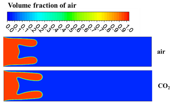
Figure 3.
Viscous fingering morphologies under different displacing media.
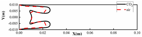
Figure 4.
Viscous fingering locations under air and CO2 displacements at the same time instant.

Figure 5.
Velocity field distributions under displacements of air and CO2 at the same time.
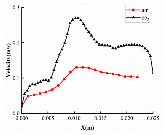
Figure 6.
Internal velocity distributions of fingers.
4. CO2 Displaces Shear-Thinning Fluids with Different Properties
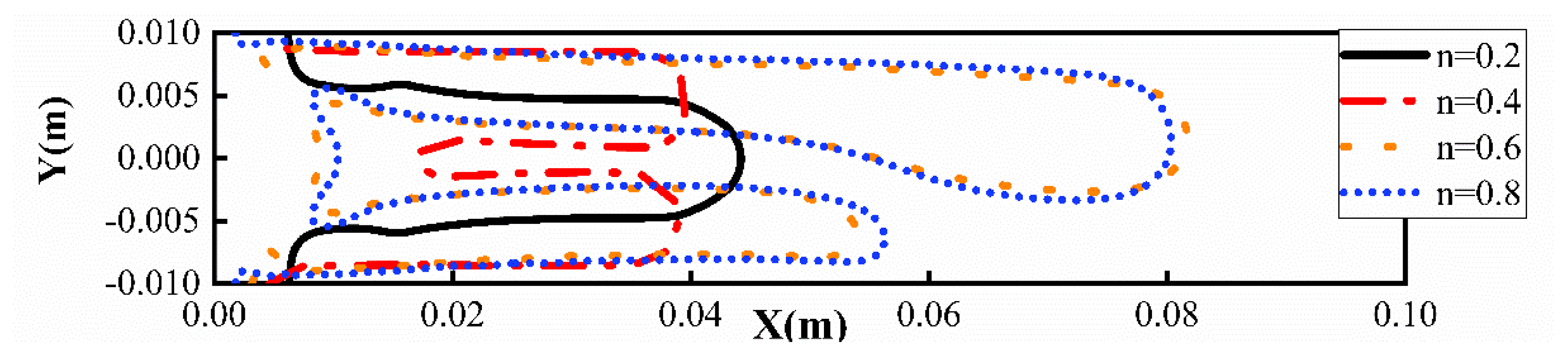
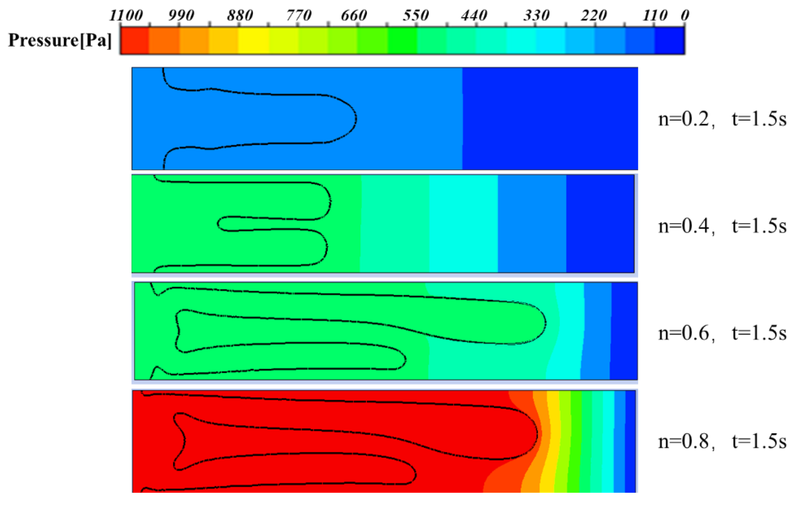
For shear-thinning fluids with different properties, a comparative analysis of viscous fingering patterns during CO2 displacement in non-Newtonian fluids with varying power-law indices was conducted at a fixed time of 1.5 s. As shown in Figure 7, at the minimum value of 0.2, corresponding to the strongest shear-thinning behavior, the displacement process exhibits no branching instability, resulting in a single, vertically symmetric finger-like structure. At , bifurcation phenomena emerge, with distinct finger-like structures displacing the fluid near the upper and lower plate regions, forming two vertically symmetric fingers. When is further increased to 0.6 and 0.8, no significant morphological distinction is observed between the displacement patterns. It can be observed that tip splitting occurs at the advancing fronts, generating dual fingering structures at the interface. Notably, one finger exhibits preferential advancement relative to the other. As clearly demonstrated in Figure 8, the shear-thinning behavior diminishes progressively with an increasing power-law index , resulting in greater fingering propagation distances. Concurrently, the fingering root thickness (marked by the black dashed line in Figure 7) increases with shear-thinning intensity. When n is 0.2, the maximum thickness of the fingering root is 0.0062 m, which is 3.4 times that when n is 0.8. This also indicates that there is less displaced fluid remaining in the displacement area. Comparative analysis across varying power-law indices reveals that shear-thinning fluids with lower values exhibit suppressed fingering instabilities. This stabilization mechanism arises from intensified viscosity heterogeneity and an elevated viscosity ratio under reduced conditions, which amplify localized shear rate gradients and promote more pronounced fingering structures. Furthermore, the pressure distribution during the displacement process was analyzed, as illustrated in Figure 9. The results demonstrate that the maximum pressure gradient consistently occurs at the tip of viscous fingers across all four cases. Notably, the internal pressure within the fingers progressively increases with a higher power-law index n, which drives enhanced finger propagation distances.
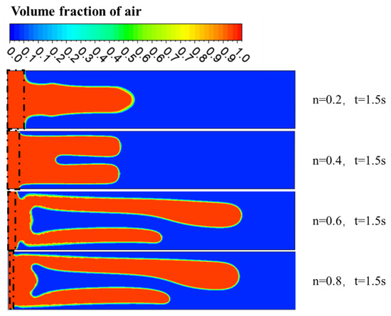
Figure 7.
The fingering contours of shear-thinning fluid under different properties of CO2 displacement.
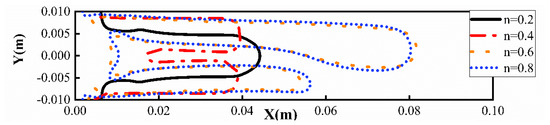
Figure 8.
The fingering positions of shear-thinning fluid under different properties of CO2 displacement.
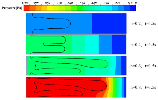
Figure 9.
Pressure contours of shear-thinning fluid under different properties of CO2 displacement.
5. Properties of Shear-Thinning Fluids Displaced by CO2 Under Different Interfacial Tensions
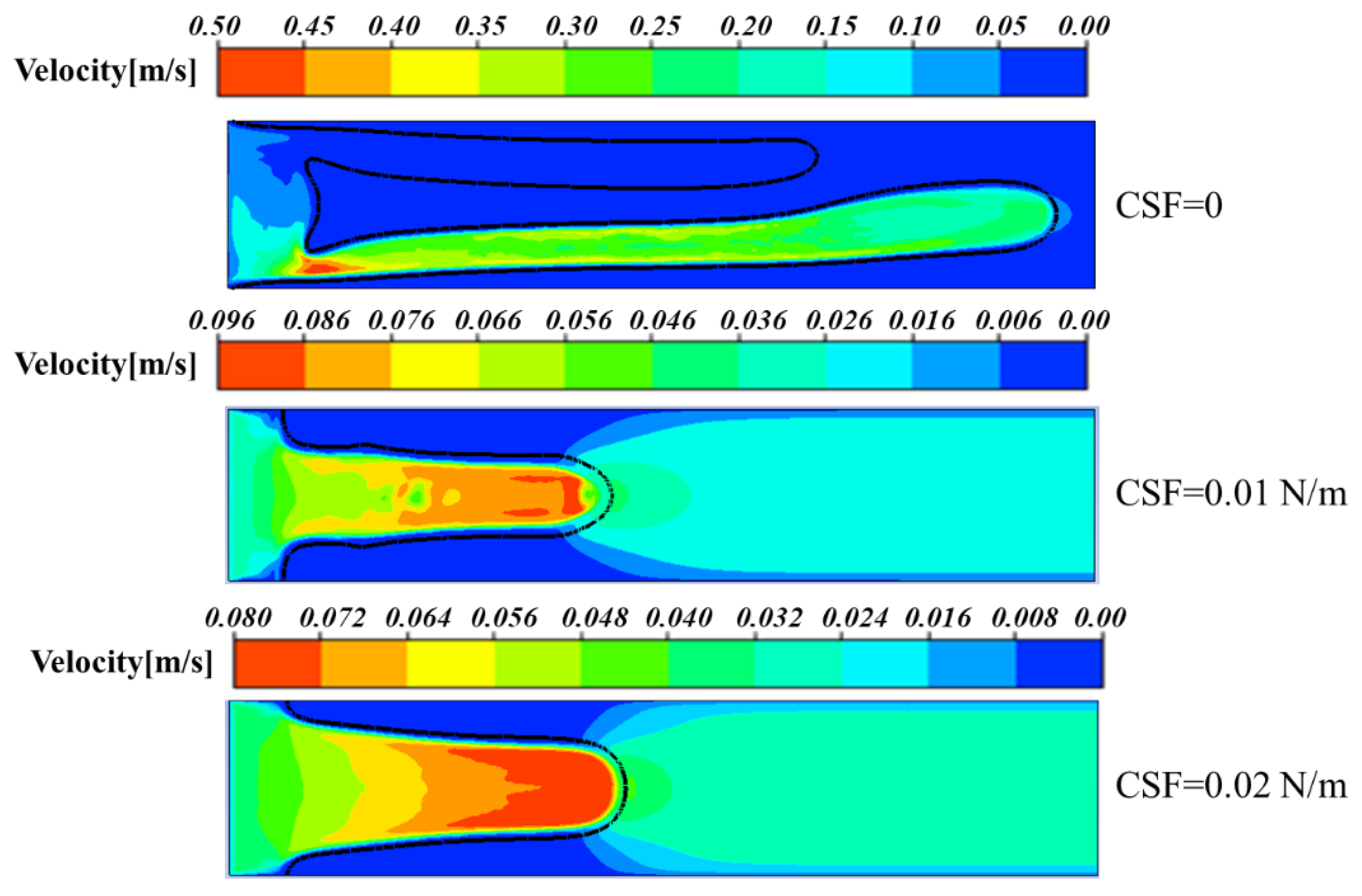
The influence of interfacial tension on viscous fingering dynamics was systematically investigated. The interfacial tension between the two phases was modeled using the Continuum Surface Force (CSF) framework, with assigned values of 0, 0.01 N/m, and 0.02 N/m. As shown in Figure 10, under zero interfacial tension that represents the extreme case of tensionless interaction between phases, viscous fingering manifests with pronounced intensity, displacing two elongated finger-like structures near the upper and lower plate regions. When interfacial tension is increased to 0.01 N/m, a single symmetric finger emerges at the interface, exhibiting roughened edges and incipient splitting tendencies. Further increasing the interfacial tension to 0.02 N/m results in a consolidated, smooth finger morphology devoid of bifurcation instabilities. Furthermore, quantitative analysis reveals that under zero interfacial tension, the maximum finger propagation distance reaches approximately 0.095 m, approaching the outlet region. In contrast, with interfacial tensions of 0.01 N/m and 0.02 N/m, the finger propagation distance is approximately 0.045 m. Concurrently, finger thickness diminishes progressively with decreasing interfacial tension. These findings confirm the stabilizing role of interfacial tension in suppressing short-wavelength perturbations, consistent with theoretical frameworks established by Saffman & Taylor [11] and Wu [29]. Short-wavelength perturbations inherently possess higher wave numbers, that is, shorter wavelengths, leading to elevated local interfacial curvature. According to the Young–Laplace equation, the interfacial curvature is directly proportional to the pressure difference induced by interfacial tension, expressed as follows:
where , denote the principal radii of curvature. For short-wave perturbations, a smaller radius of curvature produces a larger pressure difference, which quickly counteracts the perturbation. Interfacial tension can strongly suppress short-wave perturbations through curvature-driven restoring forces, higher-order wave number dependence in the dispersion relation, and energy dissipation mechanisms.
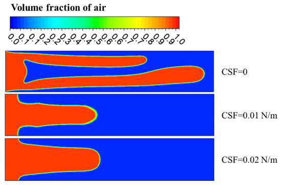
Figure 10.
Fingering contours under different interfacial tensions at 1.5 s.
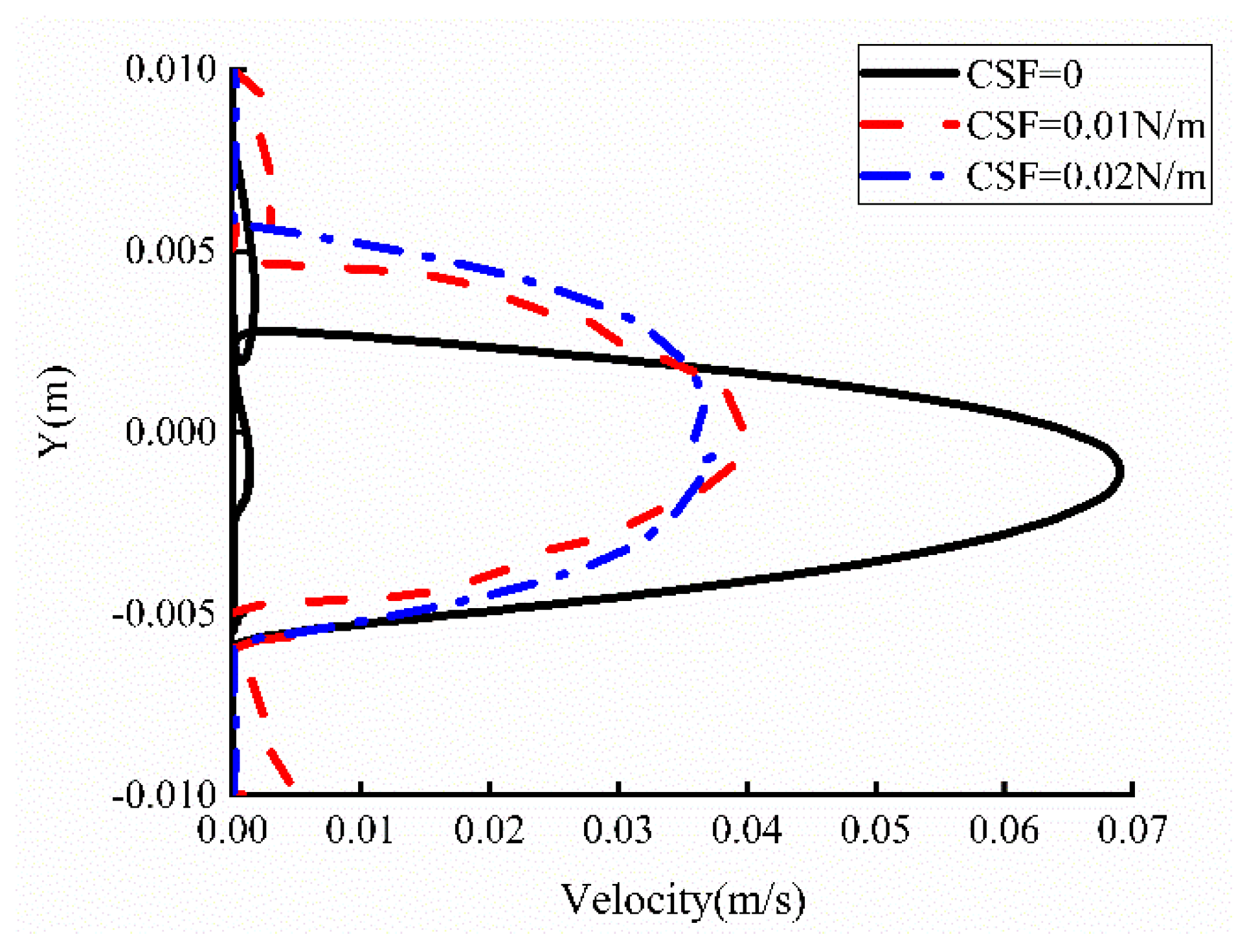
This phenomenon can also be explained through the analysis of pressure distribution contours, as illustrated in Figure 11. Regardless of variations in interfacial tension, the maximum pressure gradient consistently occurs at the tip of the viscous fingers, which promotes further propagation of the fingers. Furthermore, it is evident that the pressure magnitude is minimized when interfacial tension is a minimum, which is , corresponding to the highest velocity and consequently the farthest propagation of the fingers. As demonstrated in Figure 12, the maximum velocity is consistently localized at the fingering tip, regardless of the presence or absence of interfacial tension. Under conditions, regions of elevated velocity are predominantly distributed along the lower-region fingers, thereby driving significantly greater propagation distances for these lower-positioned fingers compared to others. Velocities along the fingering contour lines were extracted under varying interfacial tensions, as shown on Figure 13. The results reveal that the velocity at the fingering tip reaches approximately 0.07 m/s when interfacial tension is a minimum, which is . In contrast, under interfacial tensions of 0.01 N/m and 0.02 N/m, the tip velocities stabilize near 0.04 m/s for both cases. Consequently, the propagation distances of the fingering structures under N/m and N/m exhibit nearly identical advancement, consistent with their comparable velocity magnitudes. To investigate the fingering formation process, we extracted the velocities of the fingering tip at different time intervals, as depicted in Figure 14. It is observed that, in the presence of interfacial tension, the tip velocity increases rapidly during the initial stage and stabilizes gradually in later stages. Conversely, when interfacial tension is a minimum, which is , the tip velocity exhibits a sharp initial surge due to the onset of bifurcation, where the flow channel cross-sectional area decreases, accelerating the flow velocity. During the period from 0.3 s to 0.8 s, the velocity decreases as both fingers maintain identical lengths and velocities, driving synchronized development. After 1 s, the upper finger under zero interfacial tension begins to degenerate, while the lower finger continues to propagate, ultimately causing an increase in the tip velocity. This demonstrates that during CO2 displacement of non-Newtonian fluids, the presence of interfacial tension significantly influences fingering formation and velocity, while the magnitude of interfacial tension exerts a weaker effect on the fingering dynamics.
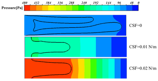
Figure 11.
Pressure contours under different interfacial tensions at 1.5 s.
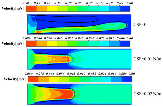
Figure 12.
Velocity contours under different interfacial tensions at 1.5 s.
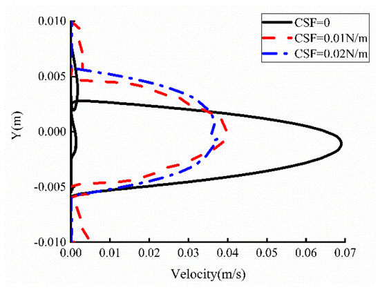
Figure 13.
Velocity distributions along the fingering contour at 1.5 s.
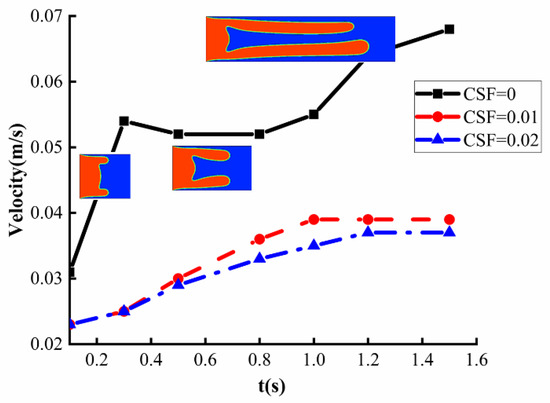
Figure 14.
Speeds of the fingering tip at different times.
6. Conclusions
In this study, numerical simulations were conducted to investigate CO2 displacement of shear-thinning fluids in a three-dimensional HSC. Analyses focused on viscous fingering dynamics under two displacing fluids, which are air and CO2, with distinct rheological properties and varying interfacial tensions. The key findings are summarized as follows:
- For both air and CO2 as displacing fluids, branching occurs during displacement, forming symmetrical upper and lower fingers. Throughout the fingering structures, velocities under CO2 displacement exceed those under air displacement. This is attributed to CO2’s ability to significantly reduce crude oil viscosity through dissolution and swelling effects. The shear-thinning effect further diminishes flow resistance in high-velocity channels, enhancing flow velocity. Consequently, viscous fingering under CO2 displacement propagates farther, achieving higher displacement efficiency compared to air displacement.
- The shear-thinning behavior of non-Newtonian fluids significantly impacts CO2 displacement processes. Enhanced shear-thinning behavior improves interface stability and weakens viscous fingering instability. Concurrently, fingering root thickness increases with shear-thinning intensity, peaking at , which minimizes residual displaced fluid in the displacement zone. This arises from amplified viscosity heterogeneity and elevated viscosity ratios under lower n, which intensify fingering prominence.
- For varying interfacial tensions, it is observed that increasing interfacial tension enhances interface stability. When interfacial tension is a minimum, which is , viscous fingering becomes highly pronounced, with two elongated fingers displacing fluid near the upper and lower plates. In contrast, at N/m, a single, smooth coherent finger forms without bifurcation tendencies. This demonstrates that interfacial tension effectively suppresses short-wavelength perturbations through curvature-driven restoring forces, high-wavenumber dependencies in the dispersion relation, and energy dissipation mechanisms.
The above summarizes the current research; in subsequent studies, research on CO2 displacement of non-Newtonian fluids will be carried out from two aspects. First, we will continue the simulation study by modifying the HSC (Hele–Shaw Cell) model and introducing depth gradients to explore methods for controlling viscous fingering. In addition, an experimental study on CO2 displacement of non-Newtonian fluids will be conducted to explore more viscous fingering phenomena.
Author Contributions
Data curation, Y.Q.; Funding acquisition, S.-K.L. and Z.Q.; Investigation, H.Q.; Methodology, Y.-T.W.; Project administration, Z.Q.; Supervision, Z.Q.; Validation, Y.Q. and B.L.; Writing—original draft, Y.-T.W.; Writing—review and editing, S.-K.L., H.Q. and B.L. All authors have read and agreed to the published version of the manuscript.
Funding
This research was supported by the Natural Science Foundation of Shandong Province under Grants ZR2022QE085 and ZR2024ME088, the fund of research for the next generation of academics of Gyeongsang National University in 2024, the NRF-NSFC Bilateral Collaboration Program (52411540234), the National Research Foundation of Korea (NRF) grant funded by the Korea government (MSIT) (No. RS-2019-NR040067), and the framework of international cooperation program managed by the National Research Foundation of Korea (NRF-2024K2A9A2A06013274).
Data Availability Statement
The original contributions presented in this study are included in the article. Further inquiries can be directed to the corresponding author.
Conflicts of Interest
Authors Yu-Ting Wu and Hua Qiao were employed by Zhejiang Shuanghuan Driveline Co., Ltd. Author Bing Li was employed by Shandong Dayang Mining Equipment Co., Ltd. The remaining authors declare that the research was conducted in the absence of any commercial or financial relationships that could be construed as a potential conflict of interest.
References
- Homsy, G.M. Viscous Fingering in Porous Media. Annu. Rev. Fluid Mech. 1987, 19, 271–311. [Google Scholar] [CrossRef]
- Wooding, R.A.; Morel-Seytoux, H.J. Multiphase fluid flow through porous media. Annu. Rev. Fluid Mech. 1976, 8, 233–274. [Google Scholar] [CrossRef]
- Bensimon, D.; Kadanoff, L.P.; Liang, S.; Shraiman, B.I.; Tang, C. Viscous flows in two dimensions. Rev. Mod. Phys. 1986, 58, 977–999. [Google Scholar] [CrossRef]
- Chen, X.L.; Li, Y.Q.; Liao, G.Z.; Zhang, C.M.; Xu, S.Z.; Qi, H.; Tang, X. Experimental investigation on stable displacement mechanism and oil recovery enhancement of oxygen-reduced air assisted gravity drainage. Pet. Explor. Dev. 2020, 47, 836–845. [Google Scholar] [CrossRef]
- Tsai, M.C.; Wei, S.Y.; Fang, L.; Chen, Y.-C. Viscous fingering as a rapid 3D Pattering Technique for Engineering Cell-Laden Vascular-Like Constructs. Adv. Healthc. Mater. 2022, 11, e2101392. [Google Scholar] [CrossRef]
- Grotberg, J.; Jensen, O. Biofluid mechanics in flexible tubes. Annu. Rev. Fluid Mech. 2004, 36, 121–147. [Google Scholar] [CrossRef]
- Huh, D.; Fujioka, H.; Tung, Y.-C.; Futai, N.; Paine, R.; Grotberg, J.B.; Takayama, S. Acoustically detectable cellular-level lung injury induced by fluid mechanical stresses in microfluidic airway systems. Proc. Natl. Acad. Sci. USA 2007, 104, 18886–18891. [Google Scholar] [CrossRef]
- Nadirah, L.; Abdurahman, H.; Rizauddin, D. Rheological study of petroleum fluid and oil-in-water emulsion. Int. J. Eng. Sci. Res. Technol. 2014, 3, 129–134. [Google Scholar]
- Gorell, S.B.; Homsy, G.M. A Theory of the Optimal Policy of Oil Recovery by Secondary Displacement Processes. SIAM J. Appl. Math. 1983, 43, 79–98. [Google Scholar] [CrossRef]
- Orr, F.M.; Taber, J.J. Use of Carbon Dioxide in Enhanced Oil Recovery. Science 1984, 224, 563–569. [Google Scholar] [CrossRef]
- Jha, B.; Cueto-Felgueroso, L.; Juanes, R. Fluid Mixing from Viscous Fingering. Phys. Rev. Lett. 2011, 106, 194502. [Google Scholar] [CrossRef] [PubMed]
- Saffman, P.G.; Taylor, G.I. The penetration of a fluid into a porous medium or Hele-Shaw cell containing a more viscous liquid. Proc. R. Soc. Lond. A Math. Phys. Eng. Sci. 1958, 245, 312–329. [Google Scholar]
- Dong, B.; Yan, Y.Y.; Li, W.; Song, Y. Lattice Boltzmann simulation of viscous fingering phenomenon of immiscible fluids displacement in a channel. Comput. Fluids 2010, 39, 768–779. [Google Scholar] [CrossRef]
- He, A.; Belmonte, A. Inertial effects on viscous fingering in the complex plane. J. Fluid Mech. 2011, 668, 436–445. [Google Scholar] [CrossRef]
- Al-Housseiny, T.T.; Tsai, P.A.; Stone, H.A. Control of interfacial instabilities using flow geometry. Nat. Phys. 2012, 8, 747–750. [Google Scholar] [CrossRef]
- Kang, Q.; Zhang, D.; Chen, S. Immiscible displacement in a channel: Simulations of fingering in two dimensions. Adv. Water Resour. 2004, 27, 13–22. [Google Scholar] [CrossRef]
- Shi, Y.; Tang, G.H. Simulation of Newtonian and non-Newtonian rheology behavior of viscous fingering in channels by the lattice Boltzmann method. Comput. Math. Appl. 2014, 68, 1279–1291. [Google Scholar] [CrossRef]
- Rabbani, H.S.; Or, D.; Liu, Y.; Lai, C.-Y.; Lu, N.B.; Datta, S.S.; Stone, H.A.; Shokri, N. Suppressing viscous fingering in structured porous media. Proc. Natl. Acad. Sci. USA 2018, 115, 4833–4838. [Google Scholar] [CrossRef] [PubMed]
- Zhao, B.; Mohanty, K.K. Effect of wettability on immiscible viscous fingering in porous media. J. Pet. Sci. Eng. 2019, 174, 738–746. [Google Scholar] [CrossRef]
- Zhang, J.H.; Luo, J.; Qu, S.X.; Liu, Z.H. Experimental Simulation and Multifractal Investigation of Viscous Fingering Phenomena. Bull. Sci. Technol. 1998, 8–13. [Google Scholar]
- Redapangu, P.R.; Vanka, S.P.; Sahu, K.C. Multiphase lattice Boltzmann simulations of buoyancy-induced flow of two immiscible fluids with different viscosities. Eur. J. Mech. B Fluids 2012, 34, 105–114. [Google Scholar] [CrossRef]
- Bakharev, F.; Campoli, L.; Enin, A.; Matveenko, S.; Petrova, Y.; Tikhomirov, S.; Yakovlev, A. Numerical Investigation of Viscous Fingering Phenomenon for Raw Field Data. Transp. Porous Media 2020, 132, 443–464. [Google Scholar] [CrossRef]
- Azaiez, J.; Singh, B. Stability of Miscible Displacements of Shear-Thinning Fluids in a Hele-Shaw Cell. Phys. Fluids 2002, 14, 1557–1571. [Google Scholar] [CrossRef]
- Logvinov, O.A. Viscous fingering in poorly miscible power-law fluids. Phys. Fluids 2022, 34, 063105. [Google Scholar] [CrossRef]
- Qin, Z.; Wu, Y.T.; Ma, C.; Lyu, S.K. Effect of power law on viscous fingering behavior of shear-thinning fluid in a lifted hele-shaw cell. J. Mech. Sci. Technol. 2023, 37, 3555–3562. [Google Scholar] [CrossRef]
- Mafi, M.; Qin, Z.; Wu, Y.; Lyu, S.K.; Ma, C. Research on the Interfacial Instability of Non-Newtonian Fluid Displacement Using Flow Geometry. Coatings 2023, 13, 1848. [Google Scholar] [CrossRef]
- Yang, X.; Tang, Y.; Li, M.; Li, C.; Wang, M.; Li, X.; Zhao, J. Effect of shear-thinning of non-Newtonian fluid on the crossover from capillary fingering to viscous fingering in porous media. Phys. Lett. A 2022, 449, 128364. [Google Scholar] [CrossRef]
- Singh, A.; Pandey, K.M.; Singh, Y. CFD analysis of viscous fingering in hele-shaw cell for air-glycerin system. Mater. Today Proc. 2021, 45, 6381–6385. [Google Scholar] [CrossRef]
- Wu, Y.T.; Qin, Z.; Ma, H.; Lyu, S.K. Numerical study on the characteristics of viscous fingering during the displacement process of non-Newtonian fluid. PLoS ONE 2024, 19, e0309176. [Google Scholar] [CrossRef]


Disclaimer/Publisher’s Note: The statements, opinions and data contained in all publications are solely those of the individual author(s) and contributor(s) and not of MDPI and/or the editor(s). MDPI and/or the editor(s) disclaim responsibility for any injury to people or property resulting from any ideas, methods, instructions or products referred to in the content. |
© 2025 by the authors. Licensee MDPI, Basel, Switzerland. This article is an open access article distributed under the terms and conditions of the Creative Commons Attribution (CC BY) license (https://creativecommons.org/licenses/by/4.0/).