Abstract
Aimed at hydrogen turbines, this research employs advanced noncontact cylindrical sealing and optimizes its sealing structure to enhance efficiency. Therefore, this paper considers the variable density and viscosity cylindrical sealing model with actual gas effects and explores the impact of groove parameters on load capacity, leakage, and friction force under two different temperature and pressure conditions. A multivariate linear regression analysis model is established. Subsequently, the NSGAII algorithm is used to perform multi-objective optimization design under operational conditions. The TOPSIS methods are applied to select the optimal parameters. This study shows that the groove depth of the spiral groove has the most significant impact on sealing performance when the groove depth is 2 μm.
1. Introduction
As a clean and low-carbon new energy source, hydrogen fuel has a high energy density [1]. Meanwhile, gas turbines are used in various mechanical systems and energy generation fields due to their compact size, light weight, and strong propulsive force [2]. Combining hydrogen with gas turbines can effectively reduce the use of traditional fuels, lower pollution [3], and significantly enhance the efficiency and utilization frequency of gas turbines. Consequently, countries are actively conducting research on hydrogen gas turbines and have achieved significant results. Currently, the operating pressure of F-class hydrogen turbines is 1.7 MPa, with an inlet air temperature range of 600 to 700 K, and outlet temperatures can reach 1500 to 2000 K [4]. Other classes of gas turbines may operate under even more severe conditions. However, research on seals for hydrogen gas turbines still faces many urgent technical challenges.
Sealing is a key aspect of research on hydrogen gas turbines. The optimization of the sealing structure can significantly enhance the performance and safety of the equipment. This research indicates that the use of advanced sealing structures can improve the performance of gas turbines by approximately 10% [5,6]. For gas turbines fueled by hydrogen, the potential of performance improvement through advanced seals is even greater. Cylindrical seals are particularly suitable for use in gas turbines under harsh conditions such as high vibration, high temperature, and high pressure [7,8]. The reason is their flexible structure, which can vary with the variation of operation conditions. Therefore, this research conducts an analysis of the influence of spiral groove parameters on the sealing performance of cylindrical seals with an optimized design of the groove structure in hydrogen medium.
In recent years, various scholars have researched sealing models using air as the medium, comparing the sealing performance of different groove shapes and the same groove shape under various parameter conditions, with the aim of selecting relatively optimal groove designs. Zhao solved the objective function regarding leakage rate for spiral groove cylindrical seals through orthogonal experiments and multiple linear regression to find the extrema and corresponding structural parameters, resulting in preliminary optimization results [9]. Chen optimized gas film stiffness and leakage rate as objectives by transforming them into a single objective, applying coordinate rotation and interval decrement methods to optimize the spiral groove cylindrical seal, ultimately obtaining a set of optimized parameters that significantly improved sealing performance [10]. Ma combined particle swarm optimization and genetic algorithms to optimize groove parameters for inverted T-shaped and double-layer slotted cylindrical seals, using the ratio of gas film reaction force to leakage rate as the objective function [11]. Lu aimed to optimize the ratio of load capacity to leakage rate and proposed a multistage optimization method combining three coordinate global search with iterative optimal three-parameter verification, effectively enhancing sealing performance [12]. Xiong used Fluent2020R1 software to explore the influence of groove parameters of T-shaped cylindrical seals on sealing performance, performing nonlinear regression analysis and polynomial fitting based on load capacity, leakage rate, and gas film stiffness, establishing a functional relationship with three groove parameters as independent variables [13]. Zhang focused on inverted spiral groove cylindrical seals, utilizing optimal Latin hypercube experimental design and its postprocessing module to extract key groove structural parameters affecting sealing performance, while establishing an approximate model to replace time-consuming numerical calculations. He conducted multi-objective optimization of groove structural parameters using the NSGAII algorithm, providing theoretical references for the design of groove types in cylindrical seals [14].
In summary, the existing optimization theories for cylindrical seals are continuously evolving, progressing from single-objective function extremum optimization to multi-objective ratio-based non-algorithmic design. However, there are a few theories that adopt algorithmic optimization. Current theories indicate that the performance parameters of cylindrical seals often constrain each other, making it difficult to achieve optimal values for all performance metrics under the same parameter conditions, which constitutes a typical multi-objective optimization problem that urgently requires resolution using multi-objective optimization algorithms. Notably, all of the aforementioned theories are based on air as the medium, and theoretical research on hydrogen cylindrical seals in the context of hydrogen gas turbines has yet to be thoroughly explored. Therefore, this research employs numerical simulation to calculate the performance parameters of groove cylindrical seals under different spiral parameters. Multivariable statistical methods are used to analyze the significant relationships between groove parameters and performance parameters. A multiple linear regression equation is established, with four groove parameters as independent variables and three performance parameters as dependent variables, fitting a functional relationship. Finally, for this three-objective optimization problem, a multi-objective optimization algorithm is utilized for iterative optimization, resulting in the best groove parameters corresponding to optimal sealing performance under hydrogen medium, providing a reference for the theoretical research and engineering application of hydrogen gas turbines.
2. Cylindrical Sealing Theoretical Model
2.1. Geometric Model
The structure of the cylindrical seal mainly consists of a rotating ring, a static ring, and an elastic support for the static ring, with spiral grooves (Figure 1) etched on the rotating ring. When the rotor system of the cylindrical seal rotates, the eccentric installation between the rotating and static rings creates a wedge-shaped gap. Coupled with the shear and pumping effects of the spiral grooves on the medium, a significant dynamic pressure effect is generated, which keeps the rotating and static rings apart, preventing direct contact and reducing wear. The enhanced dynamic pressure effect helps minimize the gas leakage of the sealing medium, achieving the system’s antileakage function.
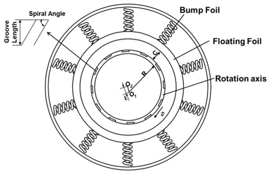
Figure 1.
The rotating ring engraved with spiral grooves.
2.2. Mathematical Model
To facilitate the research, the following basic assumptions are made for the computational model:
(1) Since the body forces and inertial forces are relatively small compared to the viscous forces, the volume forces and inertial forces of the lubricating gas are ignored.
(2) The lubricating medium is hydrogen gas, and given the relatively low rotational speed, it is assumed that the sealing gas behaves as a Newtonian fluid, with laminar flow and no turbulence.
(3) The lubricating gas is assumed to be in a state of isothermal continuous flow.
(4) The lubricating gas is a viscous fluid, so it is assumed that there is no slip during rotation.
(5) Given that the research is conducted at relatively low temperatures and pressures, it is assumed that the sealing rings are rigid and do not deform.
(6) The lubricating film is a micron-thick layer; compared to axial and circumferential pressures, the pressure variation in the radial thickness direction can be neglected.
For cylindrical seals, Brunetiere et al. summarized prior experimental studies on the lower critical Reynolds number and the upper critical Reynolds number. This implies:
Rec < 900, the flow is laminar;
900 < Rec < 1360, the flow is in a transitional regime;
Rec > 1360, the flow becomes turbulent.
The classical Reynolds equation can be applied directly for laminar flow, whereas transitional and turbulent flows require coefficient corrections to the classical Reynolds equation. Therefore, the Reynolds number is essential prior to further analysis. In this study, the minimum film thickness h is 7 μm, the maximum is 36 μm, and the shaft radius r is 25 mm. The resulting h/r ratio ranges from [2.8 × 10⁻⁴, 1.44 × 10⁻³], which satisfies the interval [10−3, 10−4]. The Reynolds number for cylindrical gas film seals is calculated as:
where is fluid density (kg/m3), is rotational speed (rad/s), r is shaft radius (m), h is film thickness (m), and is dynamic viscosity (Pa·s).
The operational temperature range is [300 K, 700 K], and the inlet pressure range is [1 MPa, 2 MPa]. Using the REFPROP property database, the calculated property ranges are as follows:
Viscosity ranges from [8.94 × 10⁻⁶, 1.611 × 10⁻⁵] Pa·s; density ranges from [0.34, 1.59] kg/m3; and film thickness is between [12 × 10−6, 3.6 × 10⁻⁵] m. Rotational speed varies from [10,000 × 2π/60, 40,000 × 2π/60] rad/s. Therefore, the calculated Reynolds number is approximately 400.
The Knudsen number, Kn, determines the applicability of continuum flow assumptions: Kn < 0.01: Continuum regime; 0.01 < Kn < 0.1: Slip flow regime; Kn > 0.1: Non-continuum regime. The Knudsen number is defined as:
where is the mean free path of gas molecules (μm), and h is the characteristic flow dimension (μm), which is equivalent to film thickness. For hydrogen gas under standard conditions, the minimum film thickness h is 1.2 × 10⁻⁵, yielding Kn < 0.01. This confirms the flow operates in the continuum regime, validating the use of the classical Reynolds equation.
2.3. Steady State Reynolds Equation
The Reynolds equation describes the distribution of pressure in the gas film during the lubrication process. Based on the assumptions mentioned above, the steady-state Reynolds equation in cylindrical coordinates is introduced.
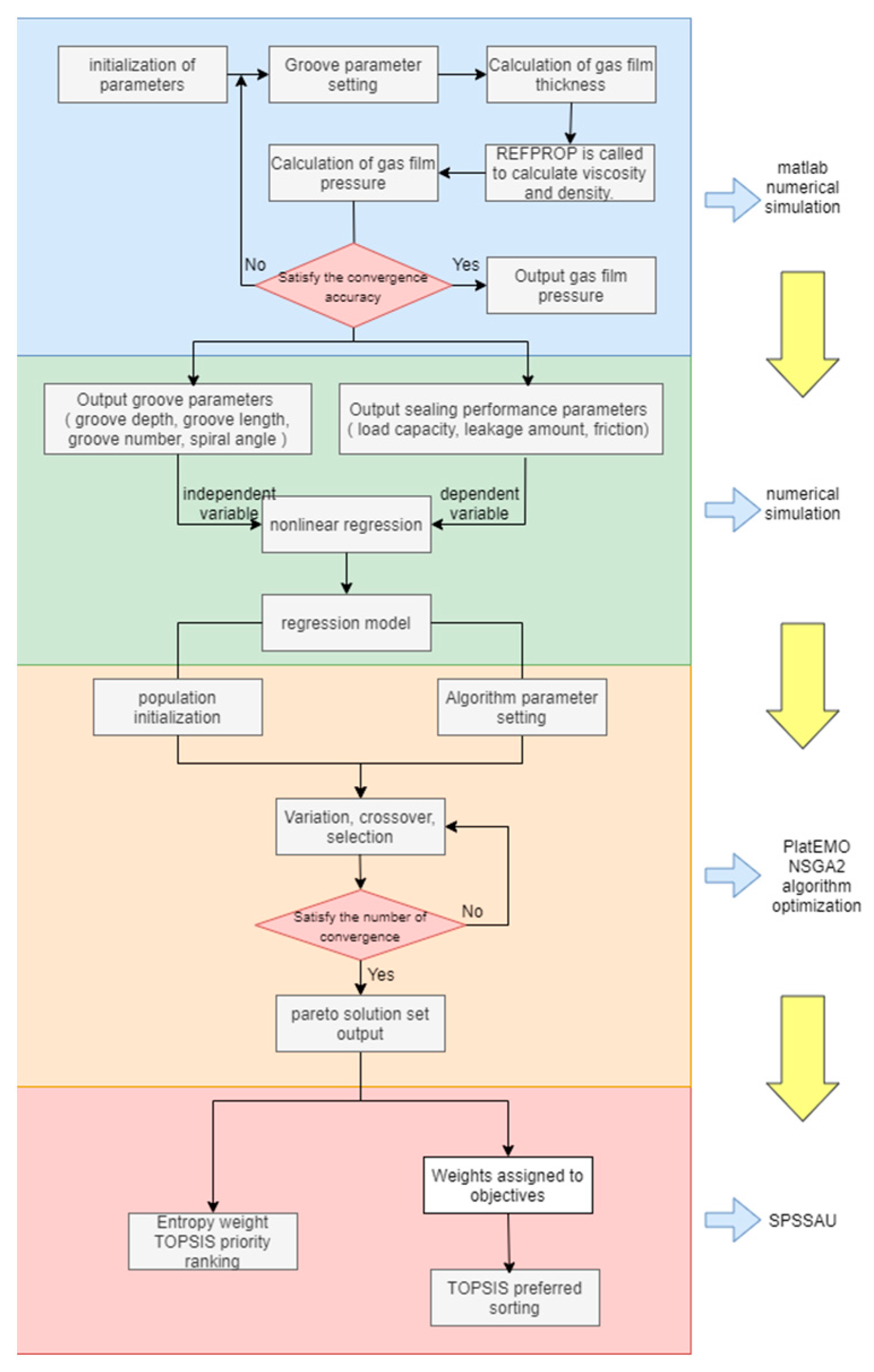
where p is the pressure of the sealing gas; R is the sealing radius; ρ is the density of the sealing gas; h is the film thickness; η is the viscosity of the sealing gas; ω is the angular velocity; θ is the circumferential direction; and z is the axial direction. The Reynolds equation is discretized using a five-point finite difference method, with initial conditions set and an iteration precision of 10−6. The final results include load capacity, friction force, and leakage amount. By adjusting the number of spiral grooves, groove width, groove depth, and spiral angle, corresponding values of sealing performance are obtained, and the reasons for these changes are explained and analyzed. Next, nonlinear fitting analysis is conducted, with spiral groove parameters as independent variables and sealing performance as the dependent variable. Subsequently, NSGAII is used for optimization design, with a population size set to 100 and 200 iterations to obtain the Pareto solution set. Finally, the best solution is selected using both subjective TOPSIS and objective entropy weight TOPSIS methods. Details are provided in Figure 2.
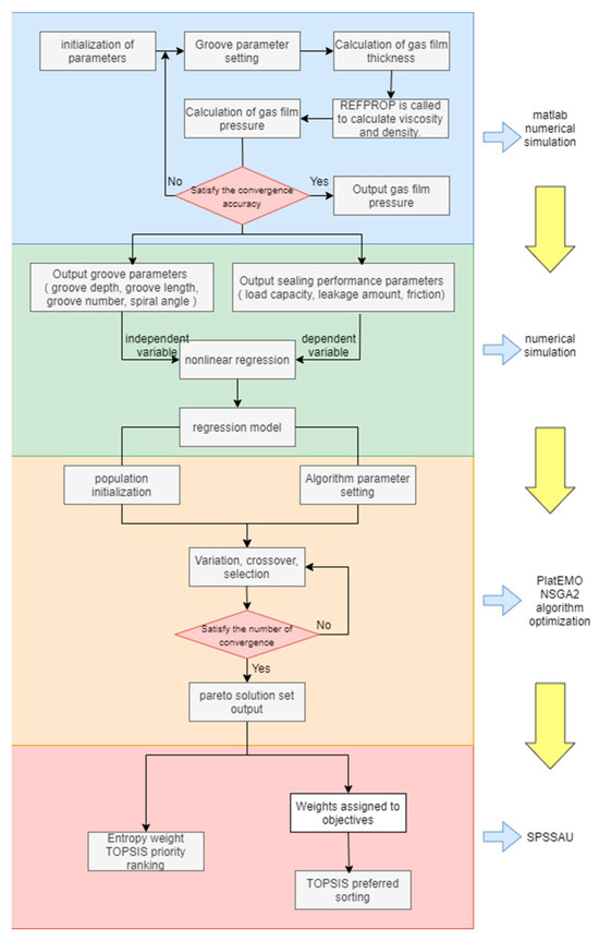
Figure 2.
The research process with spiral groove seals.
The leakage amount Q, gas film lift force F, and friction force f of the cylindrical seal are key parameters for evaluating sealing characteristics, with their respective calculation formulas as follows: Gas film load capacity:
where Fh is the dimensionless vertical component of the load capacity; Fv is the dimensionless horizontal component of the load capacity; and is the dimensioned load capacity. Leakage amount:
where is the dimensionless leakage rate, and Q is the leakage rate. Viscous friction force:
where fh is the dimensionless vertical component of the viscous friction force; fv is the dimensionless horizontal component of the viscous friction force; is the dimensioned viscous friction force where is the dimensionless pressure; is the dimensionless thickness; is the dimensionless viscosity; is the dimensionless density; C is the average gas film thickness; L is the sealing width; is the viscosity of the ambient gas; is the density of the ambient gas; and is the dimensionless axial coordinate.
To investigate the mechanisms by which structural and operational parameters affect the steady-state sealing performance of hydrogen in a supercritical state, the sealing structure from the literature is adopted, and the parameters listed in Table 1 and Table 2 are utilized for the research.

Table 1.
Structure parameter.
Table 2.
Operation parameter.
2.4. Program and Model Validation
Figure 3 shows the pressure distribution of the gas film neutral surface simulated for two types of spiral grooves under conditions of 1.8 MPa at 650 K and 1.4 MPa at 350 K, which is consistent with the trends observed in the literature [15,16]. From the figure, it can be seen that the pressure reaches its maximum value around the circumferential position of 180 degrees (i.e., near the minimum gas film thickness). This is due to the dynamic pressure effect formed between the rotating and static rings, where the pressure is subjected to the greatest compressive effect near the minimum film thickness.
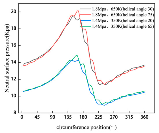
Figure 3.
Pressure distribution on midsurface.
3. Influence of Groove Parameters on Sealing Performance
To investigate the effect of groove parameters under different operating conditions on sealing performance, the analysis will focus on the influence of spiral groove count (as well as groove depth, groove length, and spiral angle) on the cylindrical seal of supercritical hydrogen at conditions of 1.8 MPa at 650 K and 1.4 MPa at 350 K, with constant rotational speed of 20,000 r/min, an eccentricity of 0.6, and an average gas film thickness of 10 μm.
3.1. Impact of Groove Number on Sealing Performance
By keeping other model parameters constant, the research starts with four grooves and increases the count by four up to a maximum of 36 grooves, calculating the sealing performance to explore the effects of groove count on load capacity, leakage rate, and friction force under the two conditions.
From Figure 4, it can be observed that the gas film load capacity and friction force increase linearly and slowly with the increase in groove count, while the leakage amount remains relatively unchanged. This is because the increase in groove count provides more space within the seal, allowing more hydrogen to be pumped into the gap between the rotating and static rings under the effects of pressure differential flow and shear flow, thereby increasing the lifting force and enhancing the dynamic pressure effect. At the same time, the vigorous collisions between hydrogen molecules lead to an increase in the friction force. The leakage amount remains unchanged because the increase in groove count allows more gas to flow in, and the enhanced dynamic pressure effect reduces leakage; however, the enlargement of the leakage pathway leads to increased leakage, offsetting the reduction, thus achieving a balance in the sealing system’s leakage. Additionally, the gas film load capacity under high operating conditions is greater than that under low conditions, while the leakage amount is smaller, indicating that the sealing effectiveness is superior under high conditions. This is attributed to the enhanced dynamic pressure effect resulting from the volumetric expansion due to increased temperature, which is greater than the reduction in dynamic pressure effect caused by the increase in pressure.
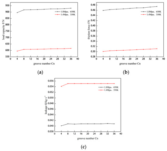
Figure 4.
Effect of groove number on sealing performance. (a) The change of gas film load capacity under two working conditions. (b) The change of friction force under two working conditions. (c) The variation of leakage under two operation conditions.
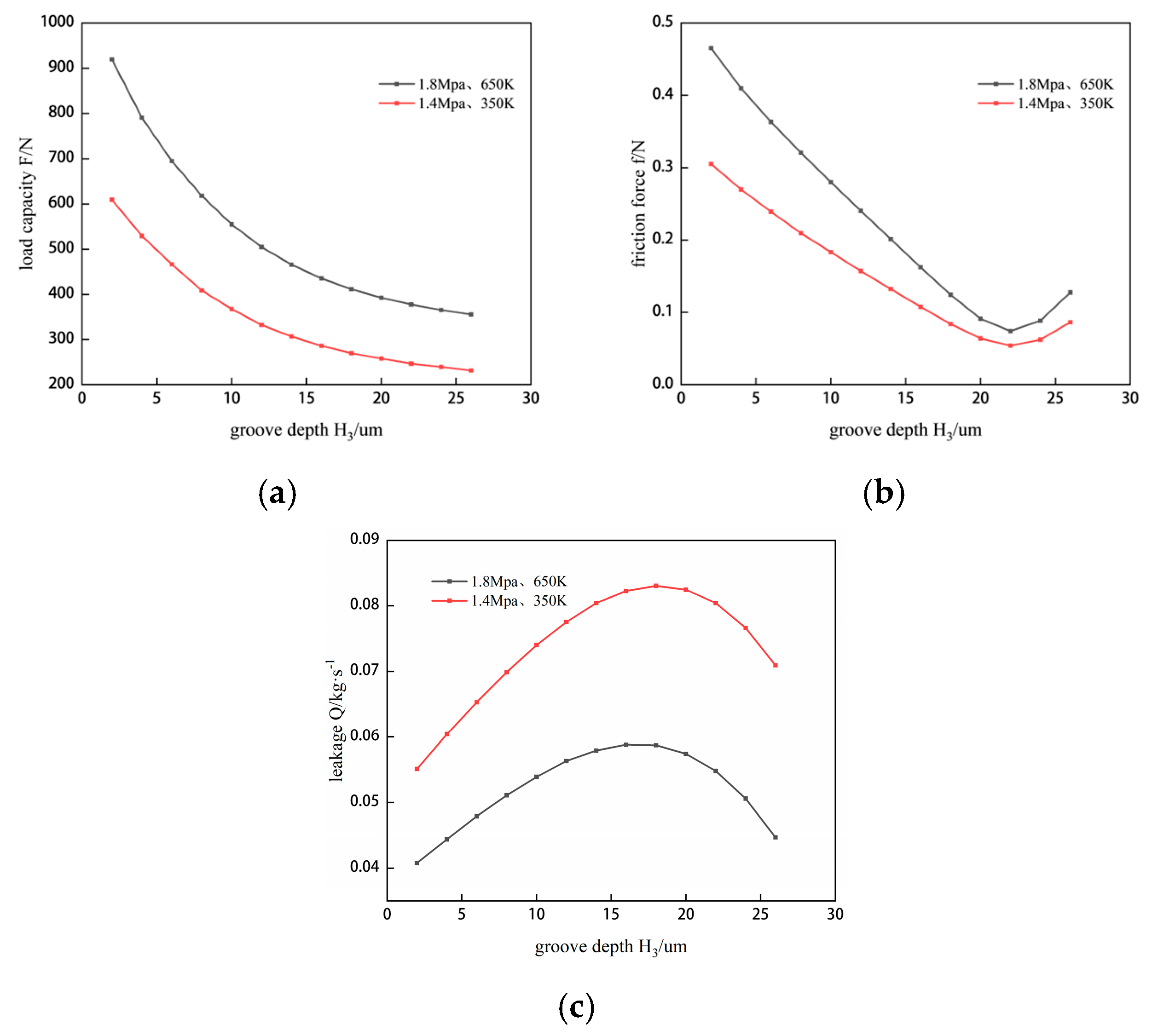
3.2. Impact of Groove Depth on Sealing Performance
Keeping all model parameters constant except for groove depth, the changes in sealing performance are examined for two conditions as the groove depth increases from 2 μm to 26 μm in increments of 2 μm.
As shown in Figure 5, the load capacity sharply decreases with increasing groove depth, while the friction force decreases continuously until a groove depth of 22 μm, after which it begins to increase. The leakage amount shows a trend of first increasing and then decreasing with the increase in groove depth, reaching a maximum at approximately 18 μm. Additionally, increases in temperature and pressure lead to an increase in load capacity and friction force, while the leakage amount decreases. This can be attributed to the increase in groove depth, which enlarges the sealing gap, effectively increasing the film thickness and thereby weakening the dynamic pressure effect of the gas film, resulting in a continuous decline in gas film load capacity and a continuous rise in leakage amount. It can be observed that the peak leakage amount at high operating conditions corresponds to a smaller groove depth than the peak at low operating conditions, indicating that the reduction in leakage amount is associated with higher conditions. Furthermore, under specific conditions, the dynamic pressure effect remains fixed; as the groove depth increases to a certain value, the gas influx accumulates significantly within the groove, thereby reducing the outflow of leaking gas and creating a sealing effect for the gas. The decrease in friction force is due to the increase in available space within the system, which leads to a dilution of hydrogen. In summary, the sealing performance under high operating conditions is superior to that under low conditions.
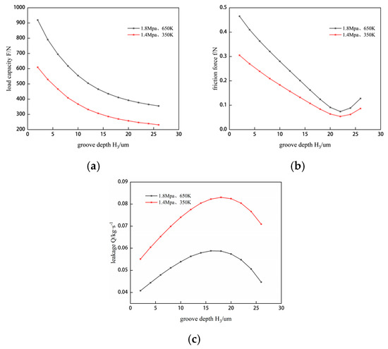
Figure 5.
Effect of groove depth on sealing performance. (a) The change of gas film load capacity under two working conditions. (b) The change of friction force under two working conditions. (c) The variation of leakage under two operation conditions.
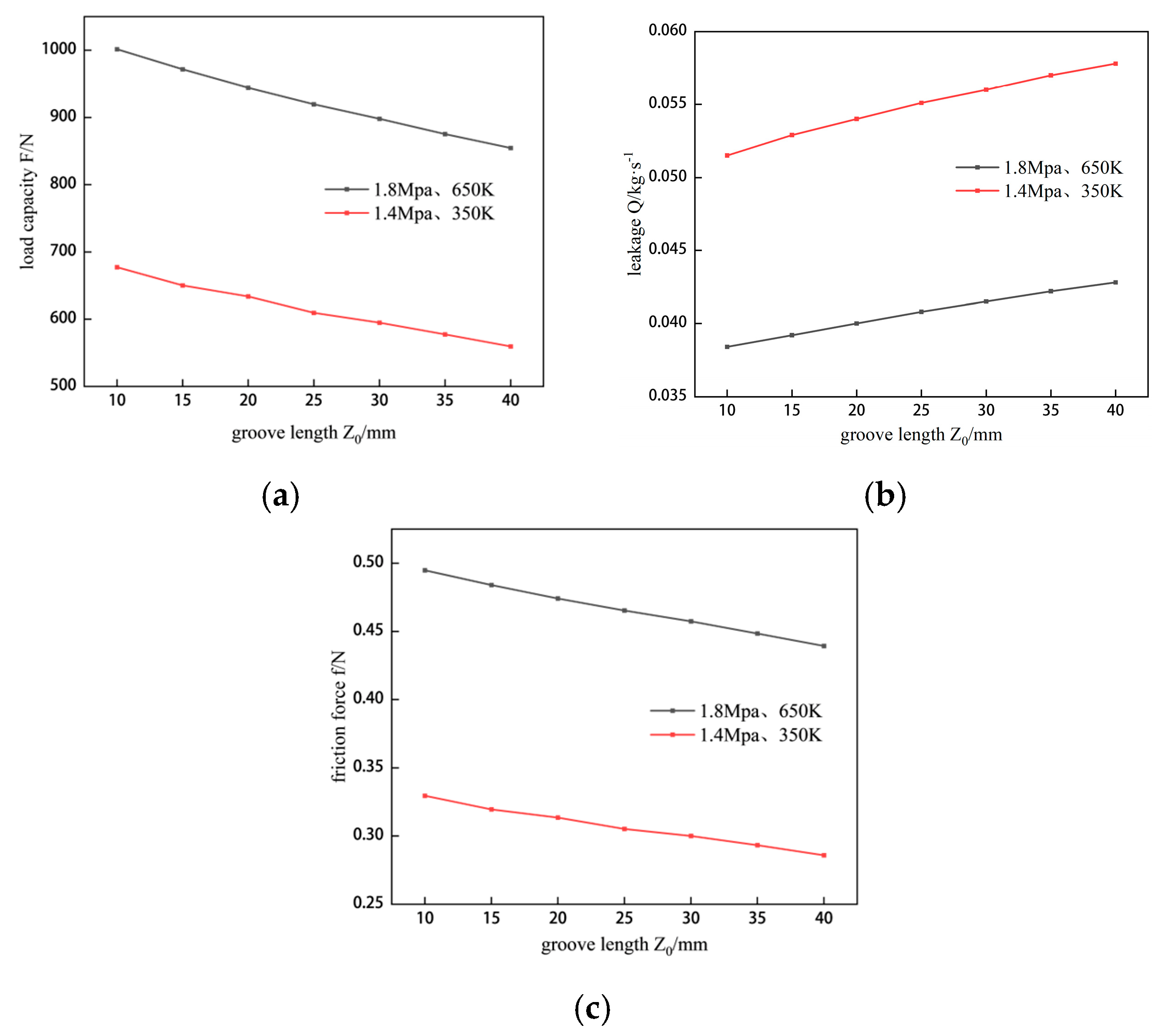
3.3. Impact of Groove Length on Sealing Performance
Using the method of controlling variables, the groove length is varied for two conditions (1.8 MPa at 650 K and 1.4 MPa at 350 K), changing the groove length from 10 mm to 40 mm in increments of 5 mm to observe the effects on load capacity, leakage rate, and friction force.
Analysis of Figure 6 shows that the gas film load capacity and friction force decrease linearly with the increase in groove length, while the leakage amount increases linearly. This is due to the increase in groove length, which enlarges the space within the sealing system. As the rotating shaft turns, more hydrogen is pumped into the gap, enhancing the dynamic pressure effect, which would typically lead to an increase in gas film load capacity and friction force, and a decrease in leakage amount. However, as gas enters, the sealing space also increases, and the effect of the increased sealing space on reduction is greater than the enhancement caused by the increased gas volume. Therefore, the overall effect is a decrease in both friction force and gas film load capacity, while the leakage amount increases. Moreover, under all groove lengths, the sealing system performance at high operating conditions consistently outperforms that at low conditions.
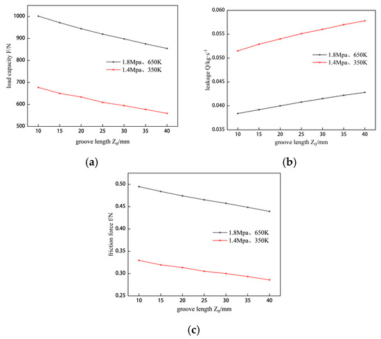
Figure 6.
Effect of groove length on sealing performance. (a) The change of gas film load capacity under two working conditions. (b) The change of friction force under two working conditions. (c) The variation of leakage under two operation conditions.
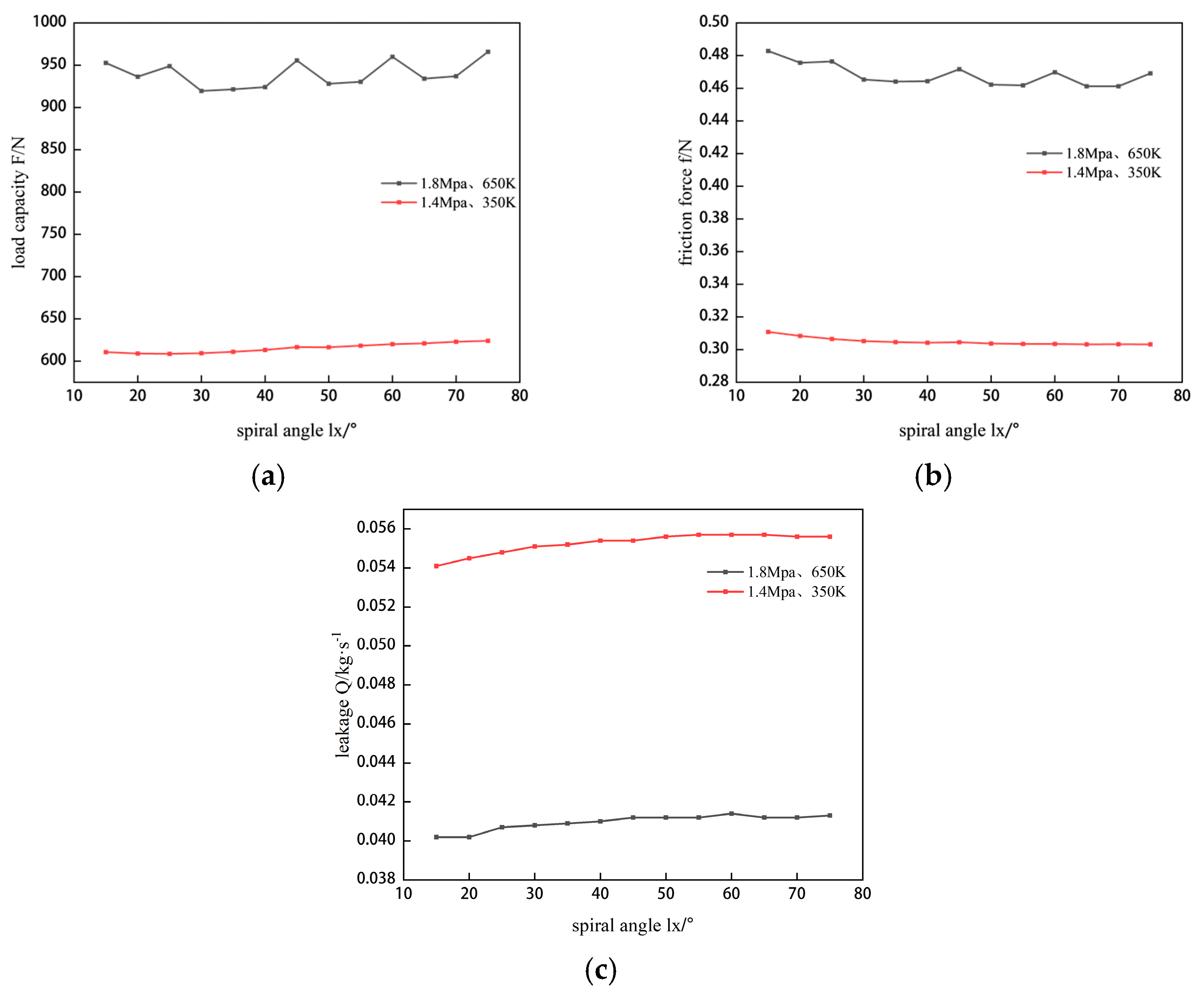
3.4. Impact of Spiral Angle on Sealing Performance
The effects of varying the spiral angle from 15 degrees to 75 degrees in 5-degree increments are studied for two conditions—1.8 MPa at 650 K and 1.4 MPa at 350 K—with other parameters kept constant, focusing on sealing load capacity, leakage rate, and friction force.
Figure 7 illustrates that at high operating conditions, the gas film load capacity shows a slight upward fluctuation with increasing spiral angle, while the friction force exhibits the opposite trend, and the leakage amount rises steadily. At low operating conditions, the gas film load capacity and leakage amount slowly increase with the spiral angle, whereas the friction force gradually decreases. The increase in load capacity at high conditions is attributed to the higher spiral angle, which allows more gas to enter the grooves, resulting in gas accumulation at the bottom of the grooves and an increase in pressure. The occurrence of fluctuations is due to the vibrations caused by higher temperature and pressure, which are not present at low conditions. Under both conditions, the increase in leakage amount is due to the fact that, although pressure increases, the dynamic pressure effect is insufficient to maintain a good sealing system. The fluctuations in friction force at high conditions are also caused by the vibration effect; however, the overall downward trend is due to the increased spiral angle allowing hydrogen to enter the grooves more linearly, thereby reducing the resistance to entry and consequently decreasing friction force. Across all spiral angles, the sealing system performance at high conditions consistently outperforms that at low conditions.
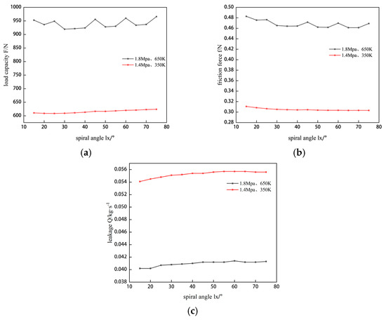
Figure 7.
Effect of spiral angle on sealing performance. (a) The change of gas film load capacity under two working conditions. (b) The change of friction force under two working conditions. (c) The variation of leakage under two operation conditions.
3.5. Nonlinear Regression Analysis of Groove Parameters
The effects of varying the spiral angle from 15 degrees to 75 degrees in 5-degree increments are studied for two conditions, 1.8 MPa at 650 K and 1.4 MPa at 350 K, with other parameters kept constant, focusing on sealing load capacity, leakage rate, and friction force.
Multivariate regression analysis can establish a mathematical relationship between the existing model groove parameters and steady state performance levels, enabling the prediction of data that has not yet been obtained. The influence patterns of groove parameters (groove length, groove depth, spiral angle, and groove number) on sealing performance (gas film load capacity, friction force, and leakage amount) indicate a nonlinear relationship among the four groove parameters and the three sealing performance factors. Therefore, a nonlinear regression model is established for nonlinear analysis and prediction.
For the two conditions, 1.4 MPa and 350 K are considered low conditions, while 1.8 MPa and 650 K are considered high conditions. The research focuses on both conditions. The groove parameters are taken as independent variables: x1 for groove depth, x2 for groove length, x3 for groove number, and x4 for the tangent of the spiral angle. The steady state performance parameters are taken as dependent variables: y1 for gas film load capacity, y2 for friction force, and y3 for leakage amount. The nonlinear regression model can be expressed mathematically as follows:
y = b1 + b2x1 + b3x2 + b4x3 + b5x4 + b6x12 + b7x22 + b8x32 + b9x42
Using programming fitting, the final regression prediction model is determined as follows:
The regression prediction model for load capacity y1 is:
Low condition: y1 = 787.155839.3745x16.0852x2 + 1.1241x3 + 13.8424x4 + 0.8703x12 + 0.0449x220.0163x322.1072x42
High condition: y1 = 1131.798460.4735x15.3730x2 + 2.8401x3 + 4.5658x4 + 1.3557x12 + 0.0113x220.0537x32 + 1.8796x42
The regression prediction model for friction force y2 is:
Low condition: y2 = 0.37970.0215x10.0015x2 + 0.0007x30.0065x4 + 0.0004x12 + 0.0013x42
High condition: y2 = 0.56020.0329x10.0009x2 + 0.0012x30.0146x4 + 0.0006x12 + 0.0034x42
The regression prediction model for leakage amount y3 is:
Low condition: y3 = 0.0407 + 0.0039x1 + 0.0002x2 + 0.0016x40.0001x120.0003x42
High condition: y3 = 0.0307 + 0.0030x1 + 0.0001x2 + 0.0012x40.0001x120.0002x42
The evaluation metrics for the multivariate regression model primarily include the coefficient of determination R2 and the adjusted correlation coefficient adjust_R2. The closer these values are to 1, the higher the accuracy of the model and the greater the credibility of the equation.
From the Table 3, it can be observed that the coefficients of determination R2 and the adjusted correlation coefficients adjust_R2 for different sealing performance metrics under various conditions of the cylindrical seal are quite close to 1. Therefore, it can be concluded that the parameters in the models for load capacity, friction force, and leakage amount are reasonable and accurate. The fitted equations can accurately predict sealing performance, indicating that the regression model is effective.
Table 3.
Evaluation index coefficient of regression model.
4. Optimization and Analysis
4.1. Optimization Based on the PlatEMO Platform
From the above analysis, it is evident that there is a mutual constraint relationship among the load capacity, friction force, and leakage amount of the hydrogen cylindrical seal; when one metric increases, another decreases. Therefore, the optimization of groove parameters is a typical multi-objective optimization problem. The NSGAII algorithm is used for optimization, with the decision variables being the groove depth x1, groove length x2, groove number x3, and the tangent of the spiral angle x4. The optimization objectives are F (load capacity), Q (leakage amount), and f (friction force), forming a four-variable, three-objective optimization problem. This can be expressed as:
Objective Functions:
minG(x) = (F(x), f(x), Q(x))
Decision Variables:
X = (x1, x2, x3, x4)
Subject to the following constraints on the variables:
Based on the above models for the two conditions, the PlatEMO platform is used to define the objective functions of the problem according to the model, along with the constraints on the variables [17]. The NSGAII algorithm is set with a population size of 100. The maximum iterations are 200, resulting in the Pareto solution set and the optimized population.
4.2. Selection of the Optimal Solution
After the iterative optimization using the NSGAII algorithm, 100 sets of populations containing groove parameters and sealing performance are obtained. In multi-objective optimization problems, it is difficult to find a set of groove parameters that optimizes every objective. There are many methods to address the conflicting nature of each objective, such as the weighted method and the ideal point method. The mathematical relationship for the weighted method is:
where Gbest is the optimal result; wF is the weight coefficient for load capacity; wf is the weight coefficient for friction force; and wQ is the weight coefficient for leakage amount.
Gbest = wFF(x) + wff(x) + wQQ(x)
4.2.1. Entropy Weighted TOPSIS Method
The TOPSIS method is a subjective comprehensive evaluation method suitable for multicriteria evaluation problems. It assesses options by calculating the distance to the ideal and negative ideal solutions. Since there are three conflicting performance indicators, it is difficult to make a decision to select the optimal solution, so the TOPSIS method is used to assist in decision making. The TOPSIS method generally includes normalization, standardization, scoring, and normalization.
- (1)
- Normalization
The TOPSIS method requires processing all data and converting it into a performance indicator for large-scale data. For the performance indicators, a larger load capacity is better, while lower friction force and leakage amount are preferred. Therefore, the friction force and leakage amount need to be transformed, with the transformation relationship as follows:
where xi represented the value of the indicator, and indicated the maximum value of this performance indicator.
- (2)
- Standardization and Normalization
The purpose of standardizing the normalized matrix is to eliminate the impact caused by different units in the calculations. Assuming there are m options and n performance indicators, the resulting normalized matrix is as follows:
To standardize the above matrix, the standardization relationship is as follows:
The resulting standardized matrix is denoted as Z.
- (3)
- Calculating the Score
From the standardized matrix, find the ideal solution distance set and the worst solution distance set.
Next, calculate the Euclidean distance between each solution and the ideal solution as well as the worst solution, using the following method:
Calculate the overall score:
In the formula: 0 < Si < 1, each object is ranked according to its value. The higher the value, the better the object. Based on the existing research on the performance of cylindrical seals, both leakage rate and load-carrying capacity are major research objectives. However, in practical applications, the leakage rate is of greater concern, while lubrication friction is relatively less significant. Therefore, the weight coefficients of load carrying capacity and leakage rate are appropriately increased, while the weight coefficient of lubrication friction is reduced. As a result, the subjective weight distribution for load carrying capacity, leakage rate, and friction is set as 3:6:1 and 4:4:2 (361 and 442). The calculations were performed using SPSSAU standard version.
From the analysis Table 4 and Table 5, it can be seen that under the weight coefficients of 361 and 442, regardless of whether the operating conditions are high or low, the optimal values for the top three spiral groove parameters and their sealing performance show that the groove depth and groove length are generally 2 and 10, respectively, while other parameters exhibit differences. This not only indicates that a groove length of 10 and a groove depth of 2 are the optimal parameters, but also highlights that groove length and groove depth have a significant impact on the overall performance of the sealing system. Furthermore, under low operating conditions for both weight coefficients, the optimal groove parameters remain the same, while under high operating conditions, they differ. This suggests that as the operating conditions increase, the changes in the entropy values of various sealing performances lead to adjustments in the weight coefficients, thereby influencing the degree to which the system’s overall performance is determined.
Table 4.
The top three rankings of the solution set with weight 3:6:1.
Table 5.
The top three rankings of the solution set with weight 4:4:2.
4.2.2. Entropy Weight TOPSIS Method
Information is an indicator of the degree of order in a system, while entropy measures the degree of disorder. According to the definition of information entropy, the degree of dispersion of a particular indicator can be assessed using its entropy value. The smaller the information entropy value, the greater the degree of dispersion of the indicator, and the larger its impact (i.e., weight) on the overall evaluation. If the values of an indicator are completely identical, the indicator will be ineffective in the overall evaluation. Therefore, information entropy can be used to calculate the weights of various indicators, providing a basis for multicriteria comprehensive evaluation.
The entropy weight TOPSIS method is based on the TOPSIS approach, where the entropy weight method determines the weight of each performance indicator based on the data, and the performance indicator data is multiplied by the corresponding weights to obtain new indicator data. This is an objective method that does not rely on human subjective intentions. The calculations were performed using the SPSSAU platform, and the weight coefficients for each indicator are as follows:
From the Table 6, it can be seen that the sealing performance weights determined by the objective entropy weight TOPSIS method vary under different operating conditions. Under high operating conditions, the entropy value of friction is the smallest, indicating the greatest degree of dispersion, with a weight of 38.93%, followed by the leakage amount and load carrying capacity. In contrast, under low operating conditions, the leakage amount has the largest weight in the overall performance, accounting for 41.22%, followed by friction and load carrying capacity. The calculated weight coefficients are multiplied by the normalized data, and the comprehensive scores of the optimization results are ranked according to the TOPSIS method, with the top three results being selected. The results are shown in Table 7 below:
Table 6.
Summary of weight results calculated by entropy method.
Table 7.
TOPSIS optimal parameters of entropy weight method.
From Table 7, it can be seen that the optimal values for the top three spiral groove parameters, including groove depth and groove length, generally remain at 2 and 10, while the other two parameters change. This indicates that groove length and groove depth have a significant impact on the overall evaluation, while the number of grooves and the spiral angle have a secondary effect. Additionally, under high operating conditions, the larger weight coefficient of friction results in a smaller load carrying capacity compared to the value chosen by the TOPSIS method, while the leakage amount is larger, and friction is the smallest. Therefore, there are differences between the results obtained using subjectively defined weights and those derived from objective calculations.
Furthermore, from the two tables based on the TOPSIS method, it could be seen that for low operating conditions, both the two weight sets from the TOPSIS method and the weights calculated by the entropy weight TOPSIS method yield results consistent with the optimized parameters. However, under high operating conditions, the optimization parameters corresponding to the weights derived from different methods vary. The entropy weight method suggests that the optimization focuses primarily on friction, which differs significantly from the optimization parameters derived from the subjectively assigned weights. Therefore, the selection of the optimization scheme should be decided by combining both methods.
4.3. Validation of Optimization Results
To validate the effectiveness of the spiral groove parameters and steady state sealing performance obtained using the TOPSIS and entropy weight TOPSIS methods, as well as the accuracy of the regression model, the obtained groove parameters are substituted into the supercritical hydrogen cylindrical seals model for calculation. The ratio of 3:6:1 in the TOPSIS method is referred to as topsis361, and the ratio of 4:4:2 is referred to as topsis442. The calculation results are shown in Table 8 below:
Table 8.
Optimization results of different methods and weights.
From the Table 8, it can be seen that under low operating conditions, the optimization results for all schemes are consistent, with improvements in load carrying capacity and leakage performance, while friction performance decreases. Under high operating conditions, the optimization results obtained using the entropy weight TOPSIS method show a significant improvement in friction performance, while load carrying capacity decreases sharply and leakage rate slightly declines. For the two schemes using the TOPSIS method, both load carrying capacity and leakage rate performance improve, while friction slightly decreases. Based on practical application conditions, it can be concluded that under high operating conditions, the spiral groove optimization results should not adopt the entropy weight TOPSIS method, but are better suited to the subjective TOPSIS method. The choice of method should depend on the specific problem, as there is no absolute superiority or inferiority between the methods; combining both will be more beneficial for the judgment of the results.
5. Conclusions
This research primarily draws the following conclusions:
(1) The influence of spiral groove parameters on the sealing performance of supercritical hydrogen cylindrical seals was explored through numerical simulations. It was found that the sealing performance under pressure of 1.8 MPa and temperature of 650 K is better than that under a pressure of 1.4 MPa and temperature of 350 K. Groove depth has the most significant impact on sealing performance, followed by groove length. There is a linear relationship between groove length and sealing performance, while the effects of spiral angle and groove number are relatively small.
(2) Nonlinear fitting of the spiral groove parameters and sealing performance for the two operating conditions was performed, resulting in the establishment of a nonlinear regression model with good predictive capability, which can replace the complex and cumbersome numerical simulation solving process.
(3) The NSGA2 algorithm on the platform was used for intelligent algorithm optimization of the regression model, combined with subjective TOPSIS and entropy weight TOPSIS for the selection of the Pareto optimal set. Groove depth and groove length are fixed at certain values, indicating that they have a significant effect on sealing performance, consistent with the previous findings. The optimal selection of spiral groove parameters differs when using two methods and two weight sets for optimization under two operating conditions. The optimal parameters for different operating conditions are not the same. Therefore, the optimal spiral groove parameters suitable for a supercritical hydrogen cylindrical seal should be selected by combining the actual demand weight with the results of subjective and objective methods.
Author Contributions
Conceptualization, methodology and software, X.W. (Xueliang Wang) and Z.G., ; validation, W.Z., J.L., and L.W.; formal analysis and writing, X.W. (Xueliang Wang); Project administration and hardware simulation, M.J., X.W. (Xuejing Wu). All authors have read and agreed to the published version of the manuscript.
Funding
This research presented in this paper was supported by the Ningbo Yinzhou District Technological Innovation Challenge (No. 2025YZQ090007), the Natural Science Foundation of Ningbo (No. 2023J271), the Scientific Research Fund of Zhejiang Provincial Education Department (No. Y202454719), and Science and Technology Innovation 2025 Major Projects (Nos. 2023Z009, 2023Z010).
Data Availability Statement
The datasets presented in this article are not available because these data include the achievements with company, the data are part of an ongoing study or due to technical limitations. Requests to access the datasets should be directed after the products public.
Acknowledgments
My sincere thanks and appreciation to my team at the Key Laboratory of Advanced Seals for their encouragement and insight into this study. In addition, I am grateful to all those who devoted time to reading this thesis and gave me suggestions, which will benefit me in my later studies.
Conflicts of Interest
Authors Min Jiang, Leibo Wu, and Xuejing Wu are employed by Ningbo Tiangong Fluid Technology Co., Ltd. The remaining authors declare that the research was conducted in the absence of any commercial or financial relationships that could be construed as a potential conflict of interest.
References
- Yin, Z.; Jiang, L.; Liu, Y.; Liu, H.; Li, S.; Wang, L.; Yu, Q.; Li, S.; Mi, J.; Hao, L. Key technologies and current situation of hydrogen energy utilization. Sol. Energy 2024, 363, 18. [Google Scholar]
- Wu, S. Application and future development trends of gas turbine technology. Energy Conserv. 2024, 43, 118–122. [Google Scholar]
- Zhou, H.; Xue, J.; Gao, H.; Ma, N. Hydrogen-fueled gas turbines in future energy system. Int. J. Hydrogen Energy 2024, 64, 569582. [Google Scholar] [CrossRef]
- Jiang, Y.; Li, Y.; Zheng, K.; Zheng, Z.; Cao, S. Review of Technology and Application Status of Gas Turbines Hydrogen Blending. Intern. Combust. Engine Parts 2023, 20, 102–104. [Google Scholar]
- Lu, Q.; Jiang, J.; Meng, X.; Chen, Y.; Ma, Y.; Peng, X. Effect of the 3D layered flow channels within the rotating ring on the steady state performance of dry gas seals. Tribol. Int. 2025, 208, 110651. [Google Scholar] [CrossRef]
- Yang, X.; Zhou, Y.; Dou, X.; Jiang, L. Experimental study of self-healing of symmetric single-source magnetofluid seals with large clearances. Vacuum 2025, 238, 114269. [Google Scholar] [CrossRef]
- Ma, G.; Yang, W. Numerical simulation and parameter optimization of seal property of bidirectional rotating cylinder gas film. J. Beijng Univ. Aeronaut. Astronaut. 2016, 42, 2279–2288. [Google Scholar]
- Ma, G.; Yang, W.; Shen, X. Numerical simulation and analysis of steady state performances for face and cylinder gas film seal system. J. Aerosp. Power 2015, 30, 22–28. [Google Scholar]
- Zhao, Y.; Li, X. Optimum Design of the Rotor of Cylindrical Gas Seal Based on the Multivariate Linear Regression Method. Gas Turbine Exp. Res. 2014, 27, 31–34+47. [Google Scholar]
- Chen, T. The Groove Parameters Optimization and Numerical Simulation on Cylindrical Gas Seal. Master’s Thesis, Kunming University of Science and Technology, Kunming, China, 2015. [Google Scholar]
- Ma, G.; He, J.; Li, X.; Shen, X. Numerical Calculation of Dynamic Coefficients for Gas Film Cylinder Seal. J. Mech. Eng. 2013, 49, 55–62. [Google Scholar] [CrossRef]
- Lu, J.; Zhang, W.; Xie, F.; Jiao, Y. Performance analysis of gas film of adaptive cylindrical seal. CIESC J. 2020, 71, 346–354. [Google Scholar]
- Xiong, Z.; Liu, M.; Wei, Q.; Li, X. Nonlinear Regression Analysis of Structural Parameters of Tgroove Cylindrical Gas Film Seal under Steady State Performance. Lubr. Eng. 2023, 8, 67116. [Google Scholar]
- Zhang, W.; Feng, F.; Ren, Y.; Sun, Y. Optimal groove design of cylindrical gas seal based on approximate model. J. Lanzhou Univ. Technol. 2023, 49, 67–76. [Google Scholar]
- Wang, X.; Chen, J.; Lu, J.; Zhang, W.; Jiang, M.; Wu, X.; Wu, L. Variation of Surface Roughness on Acoustic Emission Signal Characteristics of Compliant Foil Gas Seal. Tribology 2023, 43, 1319–1329. [Google Scholar]
- Tian, Y.; Cheng, R.; Zhang, X.; Jin, Y. PlatEMO: A MATLAB platform for evolutionary multi-objective optimization. IEEE Comput. Intell. Mag. 2017, 12, 73–87. [Google Scholar] [CrossRef]
- Lv, E.; Zhou, Y.; Zhang, K.; Zhao, Y. Development of Aero-Derivative Gas Turbines Technology. Aerosp. Power 2023, 04, 15–18. [Google Scholar]


Disclaimer/Publisher’s Note: The statements, opinions and data contained in all publications are solely those of the individual author(s) and contributor(s) and not of MDPI and/or the editor(s). MDPI and/or the editor(s) disclaim responsibility for any injury to people or property resulting from any ideas, methods, instructions or products referred to in the content. |
© 2025 by the authors. Licensee MDPI, Basel, Switzerland. This article is an open access article distributed under the terms and conditions of the Creative Commons Attribution (CC BY) license (https://creativecommons.org/licenses/by/4.0/).