Article

Microstructure and Mechanical Properties of Laser-Clad Inconel 718 Coatings on Continuous Casting Mold Copper Plate

1
International Shipping Research Institute, Gongqing Institute of Science and Technology, No. 1 Gongqing Road, Gongqing 332020, China
2
Department of Mechanical Engineering, Northeast Electric Power University, No. 169 Changchun Road, Jilin 132012, China
3
Zhejiang Santian A/C Compressor Co., Ltd., No. 1 Yinxing Road, Longquan 323799, China
4
Daqing Oilfield Perforating Equipment Co., Ltd., Chuangyezhuang, Daqing 163000, China
5
Daqing Oilfield Powerlift Industry Co., Ltd., Daqing 163000, China
6
Intelligent Vehicle College, Guangzhou Polytechnic University, No. 1342 Shiliang Road, Guangzhou 511483, China
*
Author to whom correspondence should be addressed.
Lubricants 2025, 13(7), 289; https://doi.org/10.3390/lubricants13070289
Submission received: 21 May 2025 / Revised: 22 June 2025 / Accepted: 26 June 2025 / Published: 28 June 2025

Abstract

Mold copper plates (Cr–Zr–Cu alloy) frequently fail due to severe wear under high-temperature conditions during continuous casting. To solve this problem, Inconel 718 coatings were prepared on the plate surface via laser cladding to enhance its high-temperature wear resistance. The results demonstrate that the coatings exhibit a defect-free structure with metallurgical bonding to the substrate. The coating primarily consists of a γ-(Fe, Ni, Cr) solid solution and carbides (M23C6 and M6C). Notably, elongated columnar Laves phases and coarse Cr–Mo compounds were distributed along grain boundaries, significantly enhancing the coating’s microhardness and high-temperature stability. The coating exhibited an average microhardness of 491.7 HV0.5, which is approximately 6.8 times higher than that of the copper plate. At 400 °C, the wear rate of the coating was 4.7 × 10⁻⁴ mm3·N−1·min−1, significantly lower than the substrate’s wear rate of 8.86 × 10⁻⁴ mm3·N−1·min−1, which represents only 53% of the substrate’s wear rate. The dominant wear mechanisms were adhesive wear, abrasive wear, and oxidative wear. The Inconel 718 coating demonstrates superior hardness and excellent high-temperature wear resistance, effectively improving both the surface properties and service life of mold copper plates.

1. Introduction

The Cr–Zr–Cu alloy, renowned for its exceptional electrical and thermal conductivity, has been extensively utilized as mold copper plates in continuous casting systems [1,2,3]. However, these components frequently undergo mechanical wear-induced failure under extreme operational temperatures, resulting in some economic losses [4,5,6,7]. Surface modification technology has emerged as a viable strategy to enhance component service life, such as laser cladding, thermal spraying, and electroplating [8,9,10,11]. Among these techniques, laser cladding stands out as an advanced surface treatment method, enabling the deposition of coatings with high hardness, excellent wear resistance, and strong bonding strength with the substrate [12,13,14,15]. Consequently, this technology has been extensively applied in the metallurgical, power generation, and aerospace industries [16,17,18,19,20]. Common coating materials include Fe-based, Ni-based, and high-entropy alloy powders [21,22,23,24,25]. The Ni-based coatings, in particular, demonstrate outstanding tribological performance [21], corrosion resistance [22], and thermal shock resistance [23], thus making them a preferred choice for demanding environments. As a prominent Ni-based superalloy, Inconel 718 exhibits remarkable mechanical stability at high temperatures (600 °C), which is extensively applied in high-temperature environments, including the aerospace and petrochemical industries [24,25,26,27,28,29]. Some recent research has further demonstrated its effectiveness as a cladding material for surface property enhancement of metallic substrates [30,31,32].
To enhance the surface properties of copper alloys, researchers have used laser cladding techniques to deposit functional coatings. Akio et al. [33] fabricated Cu–Cr coatings on copper substrates using laser processing, achieving a 3–4 times higher microhardness than the substrate, which can be attributed to the dispersion of Cr in the coating. Chen et al. [34] demonstrated that laser-clad Ni60A coatings exhibit superior wear resistance relative to bare copper substrates. Further progress was made by Shi et al. [35], who fabricated Ni60A–Ag coatings on copper alloy substrates using laser cladding. The homogeneous distribution of Cr7C3 carbides and Ag particles in the coating contributed to a significant enhancement in microhardness. While these advancements significantly improve room-temperature microhardness and wear resistance, the coatings demonstrate limited applicability in high-temperature environments characteristic of continuous casting molds. Notably, systematic investigations into laser cladding coatings for mold copper plates that have been placed under high temperatures remain scarce in the literature. Therefore, it is essential to explore high-temperature resistant coatings on the surfaces of mold copper plates.
In this study, a protective coating was fabricated on a mold copper plate via laser cladding using Inconel 718 alloy powder as the raw material. The strengthening mechanisms of the coating were elucidated in terms of phase composition and microstructure. Additionally, the tribological properties of the coating at 400 °C were quantified and analyzed.

2. Experimental Conditions

2.1. Experimental Materials

The Cr–Zr–Cu copper alloy is used as the substrate, with a size of 50 × 30 × 10 mm. Its chemical composition is shown in Table 1. The Inconel 718 alloy powder (Xintie Metal Materials Co., Ltd., Zhengzhou, China) is used as the cladding layer material. The alloy powder size is 200~300 meshes. Its chemical composition is shown in Table 2.
The coating fabrication process via laser cladding is illustrated in Figure 1. During the experimental preparation stage, a layer of Inconel 718 powder approximately 0.5 mm thick was pre-placed on the substrate. Subsequently, the substrate was positioned on a preheating platform and subjected to a preheating treatment lasting approximately 1 min. The laser cladding process parameters are shown in Table 3.

2.2. Experimental Methods

The sample preparation and experimental methods are as follows. The cubic samples, with the dimensions of 10 × 10 × 10 mm, were obtained using wire cutting technology. The experimental testing encompassed the analysis of the coating’s phase composition, microstructural characteristics, elemental distribution, microhardness, and high-temperature wear resistance. The phase composition of the coating was tested by X-ray diffractometer (TD-3500). The cross-section of the coating was etched with a corrosion solution (HNO3:HCl = 1:3) for about 100 s. The microstructure and element distribution of the coating were observed by scanning electron microscopy (ZEISS Gemini SEM 300, Carl Zeiss Co. Ltd., Jena, Germany). The microhardness of different depths of the coating section was measured by a Vickers hardness tester (HXD-1000TMC). The test parameter was 50 gf for 15 s. The wear resistance of the coating was tested by a double friction and wear tester (MGW-02). The spherical grinding pair was Si3N4 (Φ = 6.5 mm). The test parameters were load 10 N, frequency 2 Hz, test temperature 400 °C, and friction time 20 min.

3. Results and Discussion
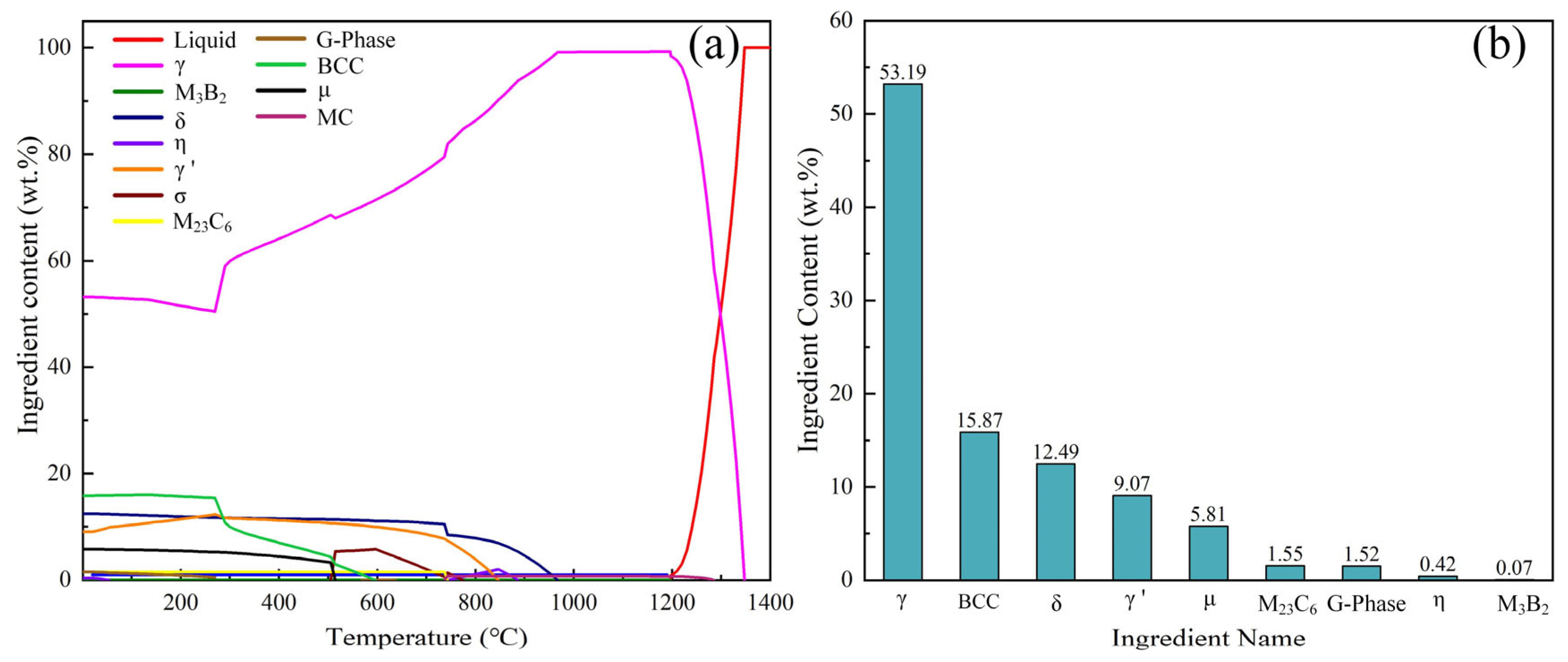
3.1. Phase

Figure 2 shows the equilibrium phase diagram of the Inconel 718 alloy solidification process simulated under ideal conditions using JMatPro software. Figure 2a shows the precipitation behavior of various phases during solidification. The γ-(Fe, Ni, Cr) phase begins to precipitate at 1350 °C, which reaches its peak mass fraction at 1230 °C. As the temperature decreases (970 °C and 290 °C), other phases start to precipitate while the relative mass fraction of γ-(Fe, Ni, Cr) decreases. Figure 2b shows the room-temperature (25 °C) composition of Inconel 718 alloy, which mainly consists of γ-(Fe, Ni, Cr), BCC, δ, γ′ phases, and carbides, such as M23C6 (M is primarily Fe and Cr). The presence of both solid solutions and carbides contributes to the improvement of alloy properties.
Figure 3 shows the XRD pattern of the Inconel 718 coating surface. The coating primarily consists of the γ-(Fe, Ni, Cr) matrix and carbide phases (M23C6 and M6C, M = Cr, Mo, Fe). This phase composition agrees well with the simulation results for Inconel 718 alloy solidification, confirming the carbide precipitation in the coating. The γ-(Fe, Ni, Cr) phase provides solid-solution strengthening, while the hard and high-strength carbides significantly enhance the coating’s mechanical properties.

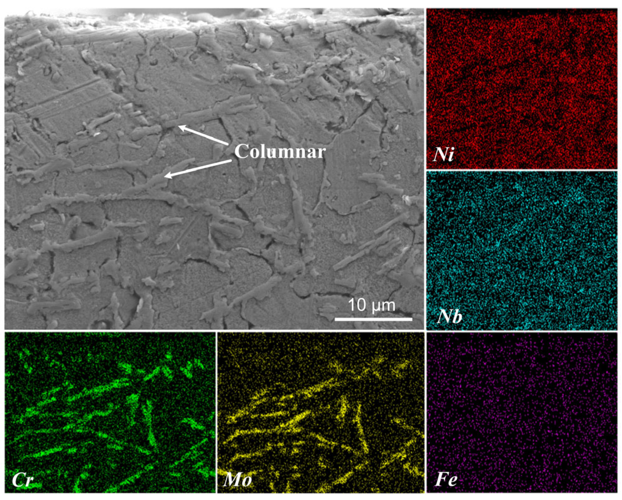
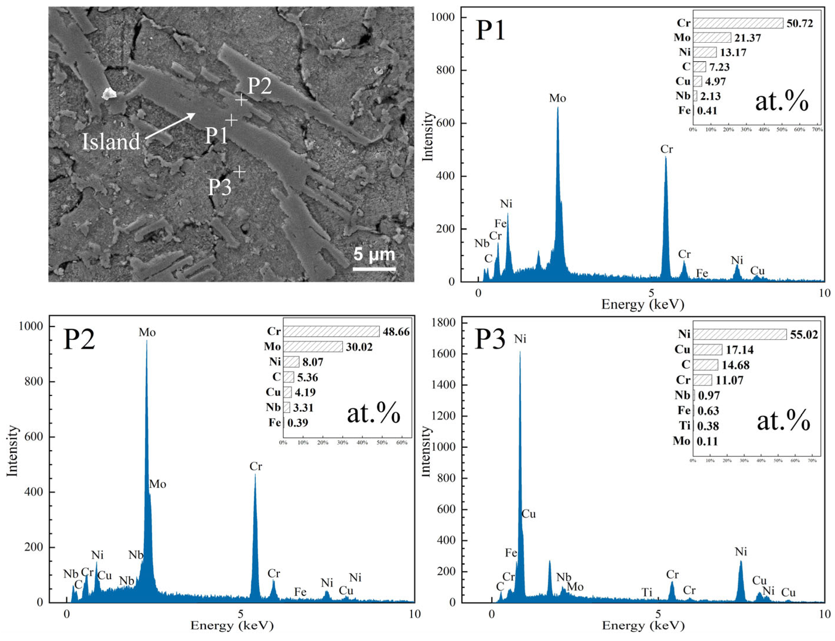
3.2. Microstructure and Element Distribution

Figure 4 shows the morphology and element distribution of the Inconel 718 coating cross-section. The coating exhibits structural integrity without pores and cracks. At the coating–substrate interfacial region, the bonding strength is significantly enhanced by the formation of a sawtooth-like interlocking interface between the coating and substrate. Elemental analysis revealed that Cu is predominantly concentrated in the substrate, while Ni, Cr, and Mo are uniformly distributed throughout the coating, and the distribution of Fe is not pronounced.
Figure 5 shows the microstructure of the Inconel 718 coating. Figure 5a indicates the selected area for local magnification. Figure 5b shows the cross-sectional microstructure of the coating’s top region, where the upper section contains numerous coarse columnar structures. In contrast, the lower region exhibits finer columnar structures distributed along grain boundaries. The higher cooling rate in this zone effectively suppresses lateral growth of columnar grains, which results in a particular refined microstructure [36]. Figure 5c shows the cross-sectional microstructure of the coating’s mid-region, which has a high density and randomly oriented columnar structures. Figure 5d shows the microstructure of the coating–substrate bonding zone. The coating’s bottom region exhibits a high density of fine columnar structures that are irregularly distributed. Compared to the substrate, the coating demonstrates significantly refined grain size, which contributes to enhanced coating hardness [33]. A distinct smooth “Band-like” zone was observed at the coating-substrate bonding zone. To investigate the elemental distribution within the “Band-like” zone, EDS line scanning was conducted and discussed later.
Figure 6 shows the microstructure of the coating top region. Elongated columnar structures are distribute along grain boundaries in the top region of the coating. These structures are enriched with Cr, Mo, and Nb elements, indicating that they are probably in the Laves phase. The Laves phase exhibits high hardness. Its elongated distribution within the coating can effectively pin dislocations, hindering their movement and contributing to dispersion strengthening to enhance the coating’s hardness [32]. Additionally, under high-temperature conditions, the Laves phase maintains relatively stable structural integrity, which effectively resists creep deformation of the coating and preserves its high-temperature wear resistance. Due to its low content, the Laves phase was not detected in the XRD analysis.
Figure 7 shows the microstructure of the island-like structures in the middle region of the coating. The central part of the coating contains irregularly shaped and coarse island-like structures. Within these structures (P1), a significant amount of Cr and Mo is present, along with a small amount of C. Therefore, these phases are likely carbides (M23C6 or M6C) or possibly Cr–Mo intermetallic compounds. Compared to the center of the island-like structures, the edges (P2) exhibit 2 at.% reduction in Cr and C content, indicating that Cr and C diffused into the molten pool during solidification. The increase in Mo suggests that Mo migrated from the molten pool into the island-like structures, which formed Cr–Mo intermetallic compounds with the existing Cr. These compounds possess high hardness, which contributes to solid-solution strengthening in the coating, thereby enhancing its hardness and wear resistance. However, due to their low concentration, they were not detected in the XRD analysis.
Figure 8 shows the EDS line-scan elemental distribution across the “Banded” zone in the bonding region. Within a distance of 40–60 μm, the Cu content is lowest near the coating side and increases sharply toward the substrate. The Ni content decreases slightly from the coating to the substrate, indicating diffusion of Ni from the coating into the “Banded” zone. Due to their similar atomic radii and high mutual solubility, Cu and Ni atoms form a substitutional solid solution, where Cu acts as the solvent and Ni as the solute (based on relative elemental intensities). A solid-solution transition zone with 20 μm width forms between the coating and substrate with a metallurgical bonding. Cr exhibits minor peak fluctuations in both the coating and substrate regions. The sharp decrease in the Cr content indicates that the diffusion of Cr at the bonding interface is limited. However, Ni and Cr can form a solid solution, which implies that the “Banded” zone primarily consists of a (Cu, Ni) solid solution, possibly with a minor amount of (Cu, Ni, Cr) solid solution.

3.3. Microhardness

Figure 9 shows the cross-sectional microhardness of the Inconel 718 coating and the substrate. The microhardness of the Inconel 718 coating is significantly higher than that of the substrate. This is attributed to the fine grain structure of the laser-deposited coating. The presence of strengthening phases in coating, such as solid solutions and carbides, enhances the coating’s microhardness [34]. The maximum microhardness of the Inconel 718 coating reaches 540.4 HV0.5, with an average microhardness of approximately 492 HV0.5 or about 6.8 times higher than that of the substrate (72.4 HV0.5). This substantial increase in microhardness significantly improves the surface microhardness of the mold copper plate.

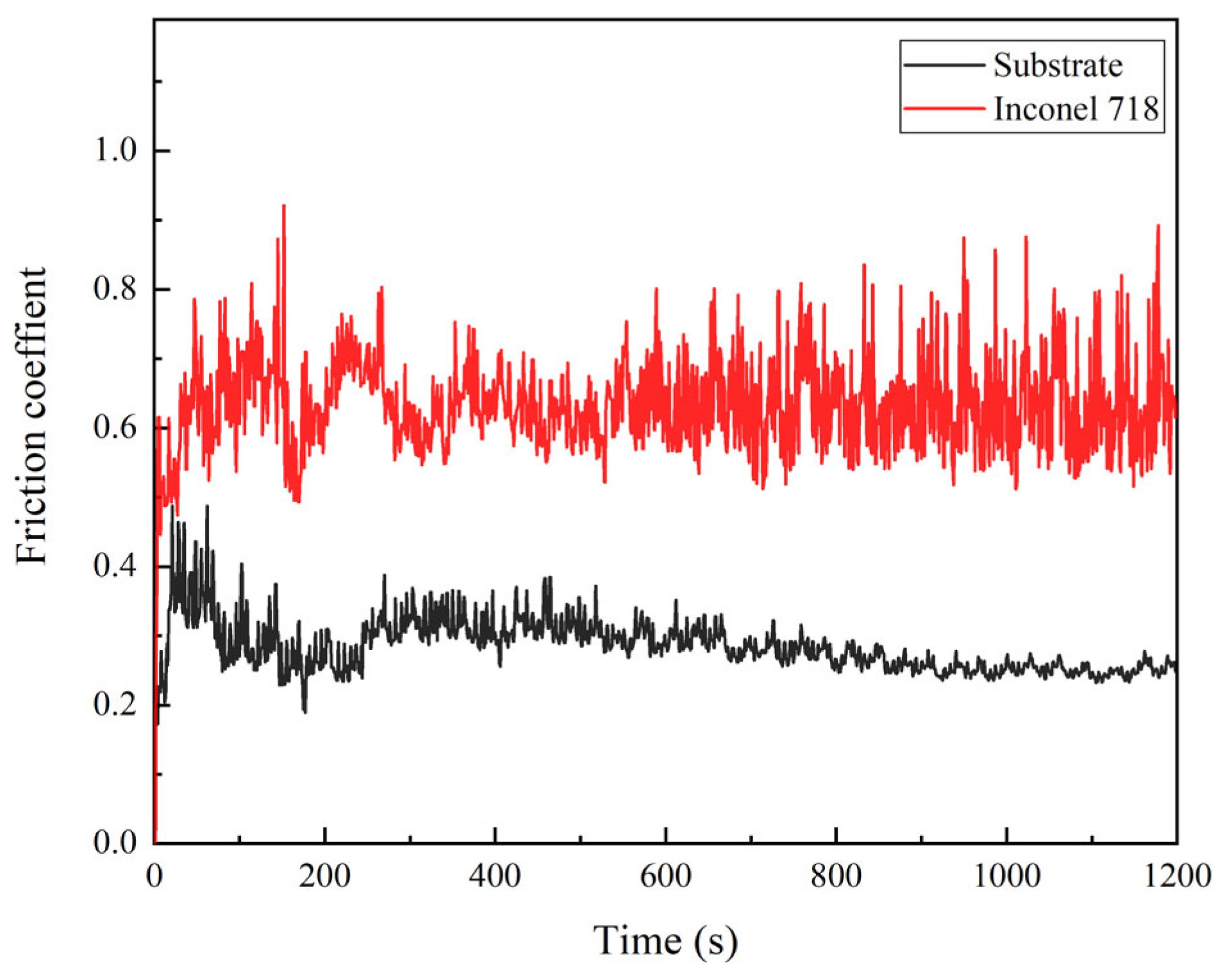
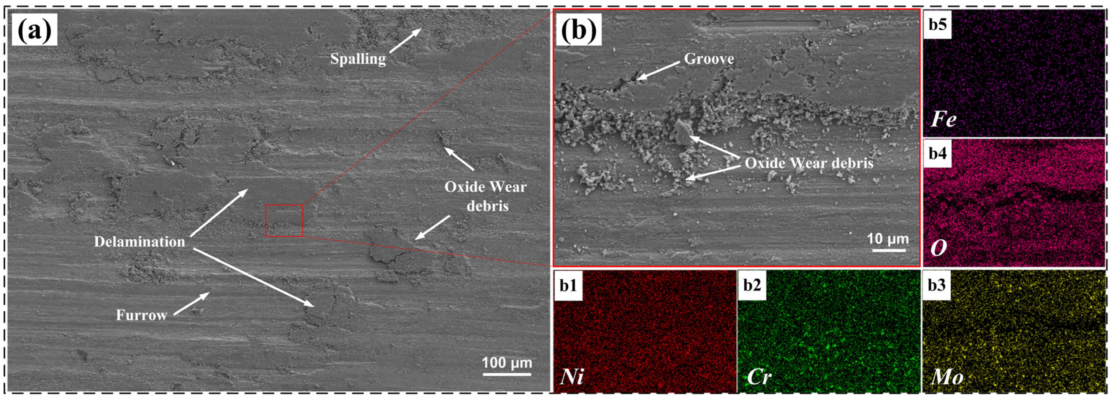
3.4. Friction and Wear Performance

Figure 10 shows the friction coefficient curves of the Inconel 718 coating and the substrate. The friction coefficients stabilize at approximately 0.29 for the substrate and 0.62 for the Inconel 718 coating. The substrate exhibits a lower friction coefficient due to the inherent softness and excellent anti-friction properties of copper. During the initial friction stage, both the coating and substrate exhibit significant fluctuations in friction coefficient due to interfacial contact between the tribo-pair and worn surface. These fluctuations indicate intense micro-cutting interactions between the grinding ball and friction surface. As the contact mode shifts predominantly to surface contact, the friction process enters a relatively stable stage, resulting in smoother friction coefficient curves. However, the Inconel 718 coating exhibits larger fluctuations in the later stage, which can be attributed to the presence of hard phases in the coating due to the involvement of high-hardness wear debris (detached from the coating) in the friction process.
Figure 11 shows the wear rates of the substrate and Inconel 718 coating at 400 °C. Under this temperature condition, the substrate displayed a wear rate of 8.86 × 10⁻⁴ mm3·N−1·min−1, while the Inconel 718 coating displayed a significantly lower wear rate of 4.7 × 10⁻⁴ mm3·N−1·min−1, which represents just 53% of the substrate’s wear rate. This remarkable wear resistance improvement can be attributed to the refined grain structure of the laser-deposited coating and the presence of multiple strengthening phases including a γ-(Fe, Ni, Cr) solid solution, carbides, a Laves phase, and Cr–Mo compounds. These microstructural features collectively contribute to enhanced hardness (as demonstrated in Section 3.3), which leads to high-temperature wear resistance.
Figure 12 shows the surface morphology and elemental distribution of the Inconel 718 coating after high-temperature friction and wear. In Figure 12a,b, the Inconel 718 coating exhibits spalling and shallow furrow, accompanied by wear debris. The spalling primarily occurs in large, flake-like patterns, which indicates characteristics of adhesive wear and abrasive wear. In Figure 12(b4), a significant presence of oxygen (O) is observed on the worn surface, which indicates the formation of an oxide film during the friction process. This confirms the occurrence of oxidative wear, as the oxide film participates in the wear mechanism.
Figure 13 shows the schematic diagrams of friction and wear for the substrate and the Inconel 718 coating. As the friction and wear test progresses, the penetration of the mill ball into the material intensifies. As shown in Figure 13a, the friction trace on the copper substrate surface is relatively deep. This is attributed to the substrate’s softer texture, larger grain size (Figure 5d), and lower hardness, which makes it more susceptible to material removal during friction against the mill ball. Due to the rapid melting and solidification characteristics, the Inconel 718 coating (Figure 13b) forms fine grains. According to the Hall–Petch relationship, finer grains contribute to higher hardness. Combined with the presence of hard phases, the coating exhibits enhanced resistance to the penetration of the mill ball during friction. However, as friction continues, hard particles detach from the coating and participate in the wear process, which leads to accelerated wear [22]. This results in significant fluctuations in the friction coefficient during the later stages of the test. Based on the wear rate analysis, the Inconel 718 coating demonstrates a lower wear rate and superior high-temperature wear resistance, which is expected to prolong the service life of copper plates.

4. Conclusions

(1)
The Inconel 718 coating was successfully prepared on the surface of mold copper plates with laser cladding technology. The coating exhibited a smooth and defect-free surface morphology. The phases identified in the coating were γ-(Fe, Ni, Cr), M23C6, and M6C (M = Cr, Mo, Fe), which aligned with the phase composition predicted by JMatPro software. The γ-(Fe, Ni, Cr) phase contributed to solid-solution strengthening, while the carbides (M23C6 and M6C) enhanced the coating’s mechanical properties.
(2)
The coating was free of pores and cracks, and it exhibited a metallurgical bond with the substrate. Cu was predominantly concentrated in the substrate, while Ni, Cr, and Mo were uniformly distributed throughout the coating. The top region of the coating contained elongated columnar grain boundaries, likely consisting of Laves phases, which contributed to dispersion strengthening. The middle region featured island-shaped carbides and intermetallic compounds that provided solid-solution strengthening.
(3)
The Inconel 718 coating exhibited an average microhardness of 491.7 HV0.5, which was approximately 6.8 times higher than that of the substrate (72.4 HV0.5). This significant enhancement is attributed to the coating’s fine grain structure and the presence of reinforcing phases. Under 400 °C testing conditions, the wear rates of the substrate and Inconel 718 coating were measured at 8.86 × 10⁻⁴ mm3·N−1·min−1 and 4.7 × 10⁻⁴ mm3·N−1·min−1, respectively, indicating that the coating’s wear rate was only 53% of the substrate’s. The superior wear resistance stems from the coating’s refined microstructure and the synergistic effects of multiple strengthening mechanisms, including a γ-(Fe, Ni, Cr) solid solution, carbide dispersion, Laves phase precipitation, and Cr–Mo compounds. These hard phases collectively enhanced the coating’s resistance to grinding ball penetration during friction, thereby resulting in excellent high-temperature wear performance. The dominant wear mechanisms are adhesive wear, abrasive wear, and oxidative wear.

Author Contributions

Conceptualization, Y.L., G.L. and Z.Z.; Methodology, N.M., H.L. and J.L.; Software, H.J.; Validation, H.L., W.X. and Z.Z.; Formal analysis, N.M. and W.X.; Investigation, H.J., G.L. and J.L.; Resources, Y.L.; Data curation, R.X.; Writing—original draft, H.J.; Writing—review & editing, Y.L. and Z.Z.; Visualization, R.X.; Supervision, G.L. and Z.Z.; Project administration, Y.L.; Funding acquisition, Y.L. and Z.Z. All authors have read and agreed to the published version of the manuscript.

Funding

We would like to acknowledge financial support from the Jiujiang Key Research and Development Program (2025_001106), the 2024 Key Research Platforms and Projects for Universities in Guangdong Province (2024KCXTD073), and the 2024 University Research Project of Guangzhou Education Bureau (2024312005).

Data Availability Statement

The data presented in this study are available on request from the corresponding author due to (specify the reason for the restriction).

Conflicts of Interest

Authors Yu Liu, Jian Lin, Wenqing Xiang were employed by Zhejiang Santian A/C Compressor Co., Ltd. Author Ruoyu Xu was employed by Daqing Oilfield Perforating Equipment Co., Ltd. Authors Nan Ma and Hui Liang were employed by Daqing Oilfield Powerlift Industry Co., Ltd. The remaining authors declare that the research was conducted in the absence of any commercial or financial relationships that could be construed as a potential conflict of interest.

References

  1. Barella, S.; Gruttadauria, A.; Mapelli, C.; Mombelli, D. Investigation of Failure and Damages on a Continuous Casting Copper Mould. Eng. Fail. Anal. 2014, 36, 432–438. [Google Scholar] [CrossRef]
  2. Srnec Novak, J.; Lanzutti, A.; Benasciutti, D.; De Bona, F.; Moro, L.; De Luca, A. On the Damage Mechanisms in a Continuous Casting Mold: After-Service Material Characterization and Finite Element Simulation. Eng. Fail. Anal. 2018, 94, 480–492. [Google Scholar] [CrossRef]
  3. Song, J.; Cai, Z.; Piao, F.; Zhu, M. Heat Transfer and Deformation Behavior of Shell Solidification in Wide and Thick Slab Continuous Casting Mold. J. Iron Steel Res. Int. 2014, 21, 1–9. [Google Scholar] [CrossRef]
  4. Yu, S.; Long, M.; Chen, D.; Fan, H.; Yu, H.; Duan, H.; Xie, X.; Liu, T. Effect of the Mold Corner Structure on the Friction Behavior in Slab Continuous Casting Molds. J. Mater. Process. Technol. 2019, 270, 157–167. [Google Scholar] [CrossRef]
  5. Thomas, B.G.; Li, G.; Moitra, A.; Habing, D. Analysis of thermal and mechanical behavior of copper molds during continuous casting of steel slabs. Iron Steelmak. 1998, 25, 125–143. [Google Scholar]
  6. Zhu, M.Y.; Cai, Z.Z. Heat Transfer Behavior and Homogenous Solidification Control for High-Speed Continuous Casting Slab Mold. Chin. J. Eng. 2022, 44, 703–711. [Google Scholar]
  7. Zhou, J.; Zhu, L.; Sun, L.; Wang, B.; Xiao, P. Analysis of the Formation Mechanism of Surface Cracks of Continuous Casting Slabs Caused by Mold Wear. Processes 2022, 10, 797. [Google Scholar] [CrossRef]
  8. Ertugrul, O.; Enrici, T.M.; Paydas, H.; Saggionetto, E.; Boschini, F.; Mertens, A. Laser cladding of TiC reinforced 316L stainless steel composites: Feedstock powder preparation and microstructural evaluation. Powder Technol. 2020, 375, 384–396. [Google Scholar] [CrossRef]
  9. Lakkannavar, V.; Yogesha, K.B.; Prasad, C.D.; Phanden, R.K.; Prasad, S.C. Thermal spray coatings on high-temperature oxidation and corrosion applications–a comprehensive review. Results Surf. Interfaces 2024, 16, 100250. [Google Scholar] [CrossRef]
  10. Lakkannavar, V.; Yogesha, K.B.; Prasad, C.D.; Mruthunjaya, M.; Suresh, R. A review on tribological and corrosion behaviour of thermal spray coatings. J. Inst. Eng. (India) Ser. D 2025, 106, 753–769. [Google Scholar] [CrossRef]
  11. Augustyn, P.; Rytlewski, P.; Moraczewski, K.; Mazurkiewicz, A. A review on the direct electroplating of polymeric materials. J. Mater. Sci. 2021, 50, 14881–14899. [Google Scholar] [CrossRef]
  12. Zhu, L.; Xue, P.; Lan, Q.; Meng, G.; Ren, Y.; Yang, Z.; Xu, P.; Liu, Z. Recent Research and Development Status of Laser Cladding: A Review. Opt. Laser Technol. 2021, 138, 106915. [Google Scholar] [CrossRef]
  13. Wang, S.; Zhu, L.; Fuh, J.Y.H.; Zhang, H.; Yan, W. Multi-Physics Modeling and Gaussian Process Regression Analysis of Cladding Track Geometry for Direct Energy Deposition. Opt. Laser Eng. 2020, 127, 105950. [Google Scholar] [CrossRef]
  14. Zhou, S.; Dai, X.; Zeng, X. Effects of Processing Parameters on Structure of Ni-Based WC Composite Coatings during Laser Induction Hybrid Rapid Cladding. Appl. Surf. Sci. 2009, 255, 8494–8500. [Google Scholar] [CrossRef]
  15. Peng, X.; Zhou, J.; Qin, Y. Improvement of the Temperature Distribution in Continuous Casting Moulds through the Rearrangement of the Cooling Water Slots. J. Mater. Process. Technol. 2005, 167, 508–514. [Google Scholar] [CrossRef]
  16. Fu, Y.; Gu, H.; Qian, L.; Li, Y.; Tong, Z.; Tao, Y.; Zhang, Z.; Yu, Z.; Ren, X. Laser Cladding for Pipeline Components: Understanding Molten Pool Dynamics and Track Formation on Outer/Inner Tube Surfaces. Opt. Laser Technol. 2024, 179, 111324. [Google Scholar] [CrossRef]
  17. Wei, Q.; Pang, X.-M.; Zhou, J.-X.; Chen, C. High Temperature Spectral Selective TiC-Ni/Mo Cermet-Based Coatings for Solar Thermal Systems by Laser Cladding. Sol. Energy 2018, 171, 247–257. [Google Scholar] [CrossRef]
  18. Liu, Z.; Jiang, Q.; Li, T.; Dong, S.; Yan, S.; Zhang, H.; Xu, B. Environmental Benefits of Remanufacturing: A Case Study of Cylinder Heads Remanufactured through Laser Cladding. J. Clean. Prod. 2016, 133, 1027–1033. [Google Scholar] [CrossRef]
  19. Comesaña, R.; Quintero, F.; Lusquiños, F.; Pascual, M.J.; Boutinguiza, M.; Durán, A.; Pou, J. Laser Cladding of Bioactive Glass Coatings. Acta Biomater. 2009, 6, 953–961. [Google Scholar] [CrossRef]
  20. Hans, M.; Támara, J.C.; Mathews, S.; Bax, B.; Hegetschweiler, A.; Kautenburger, R.; Solioz, M.; Mücklich, F. Laser Cladding of Stainless Steel with a Copper–Silver Alloy to Generate Surfaces of High Antimicrobial Activity. Appl. Surf. Sci. 2014, 320, 195–199. [Google Scholar] [CrossRef]
  21. Chen, S.; Liu, Q.; Chen, J.; Zhang, L.; Cui, T.; Sun, X. Microstructure and Tribological Performance of Novel Ni-Based Alloy Cladding with Excellent High Temperature Wear Resistance and Self-Lubrication Performance. Surf. Coat. Technol. 2024, 494, 131395. [Google Scholar] [CrossRef]
  22. Ma, X.F.; Sun, Y.N.; Cheng, W.J.; Chong, Z.Z.; Huang, L.F.; Meng, A.C.; Jiang, L.H. Effect of High-Speed Laser Cladding on Microstructure and Corrosion Resistance of CoCrFeNiMo0.2 High-Entropy Alloy. J. Cent. South Univ. 2022, 29, 3436–3446. [Google Scholar] [CrossRef]
  23. Wang, R.; Ouyang, C.; Li, Q.; Bai, Q.; Zhao, C.; Liu, Y. Study of the Microstructure and Corrosion Properties of a Ni-Based Alloy Coating Deposited onto the Surface of Ductile Cast Iron Using High-Speed Laser Cladding. Materials 2022, 15, 1643. [Google Scholar] [CrossRef]
  24. Zhang, L.; Sun, J.; Huang, X. Biomass boiler extreme high-speed laser cladding Inconel 625 coating high temperature corrosion resistance. Clean Coal Technol. 2022, 28, 65–71. [Google Scholar]
  25. Gao, M.; Li, S.; Guan, W.; Xie, H.; Wang, X.; Liu, J.; Wang, H. Excellent thermal shock resistance of NiCrAlY coatings on copper substrate via laser cladding. J. Mater. Sci. Technol. 2022, 130, 93–102. [Google Scholar] [CrossRef]
  26. McLouth, T.D.; Bean, G.E.; Witkin, D.B.; Sitzman, S.D.; Adams, P.M.; Patel, D.N.; Park, W.; Yang, J.-M.; Zaldivar, R.J. The effect of laser focus shift on microstructural variation of Inconel 718 produced by selective laser melting. Mater. Des. 2018, 149, 205–213. [Google Scholar] [CrossRef]
  27. Georgilas, K.; Khan, R.H.U.; Kartal, M.E. The influence of pulsed laser powder bed fusion process parameters on Inconel 718 material properties. Mater. Sci. Eng. A. 2020, 769, 138527. [Google Scholar] [CrossRef]
  28. Amato, K.N.; Gaytan, S.M.; Murr, L.E.; Martinez, E.; Shindo, P.; Hernandez, J.; Collins, S.; Medina, F. Microstructures and mechanical behavior of Inconel 718 fabricated by selective laser melting. Acta Mater. 2012, 60, 2229–2239. [Google Scholar] [CrossRef]
  29. Cazic, I.; Zollinger, J.; Mathieu, S.; El Kandaoui, M.; Plapper, P.; Appolaire, B. New insights into the origin of fine equiaxed microstructures in additively manufactured Inconel 718. Scripta Mater. 2021, 195, 113740. [Google Scholar] [CrossRef]
  30. Sun, P.; Yan, N.; Wei, S.; Wang, D.; Song, W.; Tang, C.; Yang, J.; Xu, Z.; Hu, Q.; Zeng, X. Microstructural evolution and strengthening mechanisms of Inconel 718 alloy with different W addition fabricated by laser cladding. Mater. Sci. Eng. A 2023, 868, 0921–5093. [Google Scholar] [CrossRef]
  31. Muvvala, G.; Karmakar, P.D.; Nath, K.A. Monitoring and assessment of tungsten carbide wettability in laser cladded metal matrix composite coating using an IR pyrometer. J. Alloys Compd. 2017, 714, 514–521. [Google Scholar] [CrossRef]
  32. Xu, P.; Zhu, L.; Xue, P.; Yang, Z.; Wang, S.; Ning, J.; Meng, G.; Lan, Q.; Qin, S. Microstructure and properties of IN718/WC-12Co composite coating by laser cladding. Ceram. Int. 2022, 48, 9218–9228. [Google Scholar] [CrossRef]
  33. Hirose, A.; Kobayashi, K.F. Surface alloying of copper with chromium by CO2 laser. Mater. Sci. Eng. A 1994, 174, 199–206. [Google Scholar] [CrossRef]
  34. Cheng, P.; Li, G.W.; Huang, P.; Pang, Z.; Li, R.; Liu, P.; Zhang, Y.; Zou, X.; Lu, X. Novel blue diode laser cladding for high-performance nickel-based coatings on copper substrates. J. Mater. Sci. Technol. 2023, 27, 780–788. [Google Scholar] [CrossRef]
  35. Cao, S.; Liang, J.; Wang, L.; Zhou, J. Effects of NiCr intermediate layer on microstructure and tribological property of laser cladding Cr3C2 reinforced Ni60A-Ag composite coating on copper alloy. Opt. Laser Technol. 2021, 142, 106963. [Google Scholar] [CrossRef]
  36. Farshidianfar, M.H.; Khajepour, A.; Gerlich, A.P. Effect of real-time cooling rate on microstructure in laser additive manufacturing. J. Mater. Process. Technol. 2016, 231, 468–478. [Google Scholar] [CrossRef]
Figure 1. The process of coating preparation by laser cladding.
Lubricants 13 00289 g001
Figure 2. The solidification process of Inconel 718 simulated by JMatPro: (a) equilibrium phase diagram; (b) phase composition at 25 °C.
Lubricants 13 00289 g002
Figure 3. XRD pattern of the surface of the Inconel 718 coating.
Lubricants 13 00289 g003
Figure 4. Morphology and elemental distribution of the cross-section of the Inconel 718 coating.
Lubricants 13 00289 g004
Figure 5. Microstructure of the Inconel 718 coating: (a) locally magnified selected area; (b) top of the coating; (c) middle of the coating; (d) coating–substrate bonding zone.
Lubricants 13 00289 g005
Figure 6. Microstructure and elemental distribution of the top region of the Inconel 718 coating.
Lubricants 13 00289 g006
Figure 7. Island structure and its point scan results.
Lubricants 13 00289 g007
Figure 8. EDS line-scan elemental distribution map of the banded region in the bonding zone.
Lubricants 13 00289 g008
Figure 9. Microhardness of the Inconel 718 coating and substrate.
Lubricants 13 00289 g009
Figure 10. Friction coefficient curves of the Inconel 718 coating and substrate.
Lubricants 13 00289 g010
Figure 11. Wear rates of the Inconel 718 coating and substrate.
Lubricants 13 00289 g011
Figure 12. Friction and wear morphology and elemental distribution of the Inconel 718 coating: (a) SEM; (b) enlarged SEM; (b1) Ni; (b2) Cr; (b3) Mo; (b4) O; (b5) Fe.
Lubricants 13 00289 g012
Figure 13. Friction and wear process: (a) substrate; (b) Inconel 718 coating.
Lubricants 13 00289 g013
Table 1. Chemical composition of Cr–Zr–Cu (wt.%).
ZrCrCu
0.250.6899.07
Table 2. Chemical composition of Inconel 718 alloy powder (wt.%).
CCrNbMoTiAlCoMnSiNiFe
0.08194.830.750.651.20.350.355515.17
Table 3. Process parameters of laser cladding.
Laser Power (W)Scanning Speed (mm/min)Spot Diameter (mm)Overlap Rate (%)Preheating
Temperature (°C)
Laser Fluence (J·mm−2)
14001203302002
Disclaimer/Publisher’s Note: The statements, opinions and data contained in all publications are solely those of the individual author(s) and contributor(s) and not of MDPI and/or the editor(s). MDPI and/or the editor(s) disclaim responsibility for any injury to people or property resulting from any ideas, methods, instructions or products referred to in the content.

