Abstract
This study presents a bioinspired phase-change transparent flexible heater (PTFH) for programmable droplet manipulation under ultralow voltage. By embedding a self-junctioned copper nanowire network into paraffin-infused, porous PVDF-HFP gel matrices, the PTFH achieves rapid, non-contact, and reversible control of microdroplet mobility. The PTFH can be bent or tailored into diverse shapes (e.g., V/X configurations), enabling multidirectional droplet transport. Under ultralow voltage actuation (<1 V), the surface of PTFH melts the phase-change lubricant within 2 s, switching surface wettability from high adhesion (Wenzel state) to low adhesion (SLIPS state). By combining Laplace pressure and temperature gradients (up to 22 °C/mm), drive droplets at ~2.0 mm/s over distances of ~13.9 mm. Programmable droplet coalescence, curved-surface transport, and a microreactor design for batch reactions were also demonstrated. The PTFH exhibits excellent transparency (89% when activated), mechanical flexibility, and cyclic stability, offering a versatile platform for microreactors, microengines, and smart windows.
1. Introduction
Surfaces with engineered wettability have attracted significant attention for their crucial roles in various applications, including water harvesting [1], enhanced lubrication [2], anti-icing [3], energy conversion [4], and biomedical diagnostics [5,6]. Inspired by natural systems—such as the self-cleaning lotus leaf [7], the insect-trapping pitcher plant [8], and the water-collecting cactus spine [9]—researchers have created functional surfaces with distinct wetting behaviors [10]. Among these, slippery lubricant-infused porous surfaces (SLIPSs), which mimic the liquid-repellent mechanisms of pitcher plants [11,12] and earthworm skins [13], show exceptional promise due to their ultralow contact angle hysteresis and omniphobicity [14].
Recent advances have enabled stimulus-responsive SLIPS that dynamically tune wettability through external triggers (e.g., magnetic fields [15,16,17], thermal [18,19], light [20], or electricity [21]). Such adaptive systems possess potential for droplet-based microengines [17], anti-icing [3], microreactors [19], and smart windows [21]. However, a critical challenge remains that existing electrically activated materials require high operating voltages (typically 3–15 V) to overcome the energy barriers for restructuring the lubricant layer or the significant hysteresis for droplet actuation [22,23,24,25,26]. This limitation impedes integration with flexible electronics, increases power consumption, and hinders precise droplet manipulation, especially for portable devices demanding low-voltage operation (<3 V) [27].
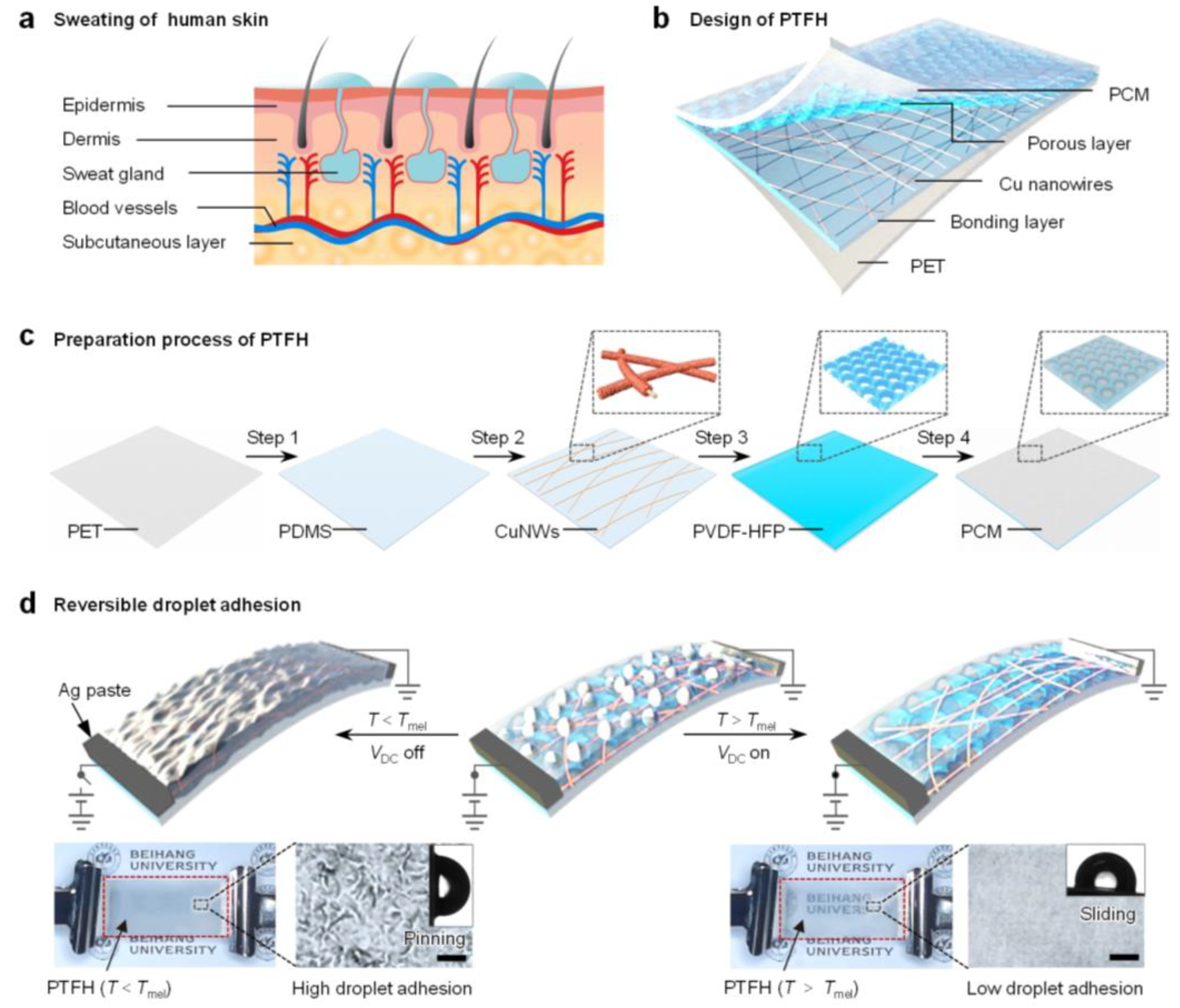
To address this gap, we draw inspiration from stimulus-responsive biosecretion mechanisms. As shown in Figure 1a, when the environmental temperature increases or the human body experiences stress, it is widely recognized that the skin secretes sweat, modulating the frictional force on its surface [28,29]. This natural mechanism serves as a paradigm for the design of a phase-change transparent flexible heater (PTFH). As depicted in Figure 1b, the PTFH comprises a polyethylene terephthalate (PET) support layer, a polydimethylsiloxane (PDMS) bonding layer, copper nanowires, a poly(vinylidene fluoride-co-hexafluoropropylene) (PVDF-HFP) nanoporous layer, and infused phase-change materials (PCM).

Figure 1.
Design of the PTFH. (a) Schematic illustration of human skin sweating in response to heat. (b) Schematic illustration of the multilayer structure of the PTFH. (c) Preparation process of the PTFH. (d) Schematics illustrate the dynamic wettability conversion of the PTFH. Insets show photographs of the PTFH and microscopic images of the PTFH surface before and after heating, along with droplet sliding angles. Scale bars: 100 μm.
As shown in Figure 1c, the preparation of the PTFH includes four key steps: (i) spin-coating an 87 μm PDMS layer onto the PET substrate; (ii) transferring Au-sputtered polyacrylonitrile (PAN) nanofibers onto the semi-cured PDMS, followed by copper electroplating for metallization and welding; (iii) casting a porous PVDF-HFP film over the copper nanowires (CuNWs); (iv) infusing PCM into the porous PVDF-HFP layer (see Section 3 and Figure S1 for details).
When the surface temperature of the PTFH (T) is lower than the phase transition temperature of the PCM (Tm) without input power, PCM solidifies, forming a micro-scale rough structure on the material’s surface (Figure 1d). The PTFH exhibits high adhesion (Wenzel’s state) to droplets. When a specific DC voltage (VDC) is applied to the built-in CuNW network to generate heat and when T > Tm, the PCM melts, and the material surface becomes smooth, resulting in a low-adhesion SLIPS state.
Based on the characteristics of the PTFH, we achieve non-contact droplet actuation through Joule heating–induced solid–liquid phase transitions, programmable mobility control enabled by biomimetic geometric gradients (e.g., cactus-inspired wedges), and ultralow-voltage operation (≥0.5 V), significantly lower than that of state-of-the-art systems. This work introduces an innovative surface design for droplet manipulation, applicable to microengines [17], microreactors [19], and smart windows [21].
2. Materials and Methods
2.1. Preparation of Materials
Polydimethylsiloxane (PDMS, Sylgard 184) silicone elastomer was obtained from Dow Corning, Midland, MO, USA. PET transparency films were purchased from 3M Co., Shanghai, China. N, N-dimethylformamide (DMF; 99.5%), polyacrylonitrile (PAN; 99.5%), poly(vinylidene fluoride-co-hexafluoropropylene) (PVDF-HFP; Mw: ~400,000, Mn: ~130,000), di-n-butyl phthalate (DBP; 99.5%), acetone (99.5%), sulfuric acid (99.5%), hydrochloric acid (99.5%), and copper sulfate (99.5%) were purchased from Sinopharm Chemical Reagent Co., Ltd., Shanghai, China. Liquid paraffin (density: 0.86–0.89) was purchased from Aladdin, Inc., Shanghai, China. and was used in the original form. Solid paraffin (Melting point: ~47 °C) was purchased from Longhuazhengze Chemical Co., Ltd., Wuhan, China.
2.2. Preparation of Transparent Flexible Electrode (TFH)
The TFH was prepared using the same method as the previous report [30]. Typically, as shown in Figure S1, preparing the TFH involves four steps. First, an 8 wt.% PAN solution was prepared by dissolving PAN in DMF and stirring magnetically for 12 h. The electrostatic spinning parameters were set as follows: injection rate of 0.1 mL/h, spinning voltage of 5 kV, and receiving distance of 15 cm. Second, a nanometer-thick gold layer was vacuum-coated onto the fibers for 90 s. Third, a PDMS primer (1200 OS) was spin-coated onto a PET film (1000 rpm, 10 s), dried at room temperature for 30 min, followed by a PDMS layer (2000 rpm, 30 s). After curing at 70 °C for 40 min, the nanofibers were transferred onto the partially cured PDMS. Finally, the PET with nanofibers was fixed with conductive copper tape, dipped in a copper plating solution as the cathode, with a pure copper plate as the anode.
A copper plating solution was prepared by dissolving 25 g of sulfuric acid, 2.5 g of hydrochloric acid, 80 g of CuSO4, and 50 g of formaldehyde in 500 mL of deionized water and stirring at room temperature for 1 h. Electroplating conditions were 3 V working voltage and 3 s plating time. After electroplating, junctioned CuNWs were obtained. The samples were then rinsed with deionized water and dried with nitrogen.
The TFH was treated with air plasma for 10 s to make its surface hydrophilic. Conductive silver slurry was then applied via screen printing to connect it with CuNWs and cured at 70 °C for 1 h.
2.3. Preparation of Porous PVDF-HFP Layer
A porous PVDF-HFP layer was fabricated using non-solvent induced phase separation (NIPS) [31]. Typically, PVDF-HFP and DBP were dissolved in acetone at 20 wt.% concentration with a weight ratio of 1:2. The solution was stirred at 50 °C for 1 h, aged at room temperature for 24 h, and then dripped onto the TFH surface. The TFH was rotated at 600 rpm for 5 s and dried at room temperature for 1 min. PVDF-HFP and DBP phase-separate during this process, forming a fixed membrane structure. The material was then immersed in ethanol for over 1 min to remove the DBP, and the porous PVDF-HFP layer was obtained via nitrogen drying.
2.4. Preparation of Phase-Change Materials (PCMs)
Solid paraffin was placed in an incubator at 90 °C for three hours to liquefy. Then, it was mixed with liquid paraffin in different proportions (curable/liquid paraffin = volume ratio 1:3) and stirred at 90 °C for 12 h [20].
2.5. Preparation of Phase-Change Transparent Flexible Heater (PTFH)
At a heating temperature of 60 °C, the solid paraffin/liquid paraffin mixture was dripped onto the porous hydrophobic film surface of the porous flexible heater (PFH) and allowed to sit for 10 min. Excess paraffin oil on the film surface was removed with nitrogen, and then the phase-change transparent flexible heater (PTFH) was prepared.
2.6. Characterization
The morphologies of the samples were analyzed using environmental scanning electron microscopy (Quanta 250 FEG, FEI, Hillsboro, America) at 10 kV. Surface elements of CuNFs were characterized using SEM–EDS (JSM-7500F, JEOL, Tokyo, Japan) at 20 kV. Transmittance was measured with a spectrophotometer (UV-3600, Shimadzu, Kyoto, Japan). Surface temperature distribution was determined via thermography (A655sc, FLIR, Goleta, CA, USA). Voltage was applied using a DC power supply (2231A-30-3, KEITHLEY, Beaverton, OR, USA). Water contact and roll-off angles were measured using an OCA 50 AF (Dataphysics, Filderstadt, Germany). Static water contact angles (CAs) were measured by dispensing a 3 μL droplet onto the test surface with a pipette and capturing a side-view image when the droplet stabilized. Sliding angles (SA) were measured by dispensing a 10 μL droplet onto the surface, aligning it with the stage’s tilting axis, and tilting it at approximately 0.5° s−1 until the droplet rolled. The sliding angle measurement was obtained using the goniometer. Tangential adhesive force was measured using an adhesion tester (DCA21, Dataphysics, Filderstadt, Germany).
3. Results
3.1. Structure and Chemical Characterization of PTFH
The cross-sectional scanning electron microscopy (SEM) image in Figure 2a reveals the multilayer structure of the PTFH (without PCM infusion). The PVDF-HFP layer exhibits a thickness of approximately 5 μm. Figure 2b displays the surface morphology of the PVDF-HFP layer, showing its interconnected porous structure. This architecture provides capillarity and inherent hydrophobicity, enabling spontaneous infusion and stable fixation of liquid paraffin [30].
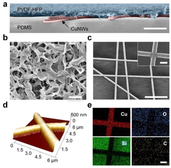
Figure 2.
Structure and chemical characterization of the PTFH. (a) SEM image (in false color) of the cross-section of the PTFH. The PTFH exhibits a multilayer structure, comprising a porous PVDF-HFP layer (blue), CuNWs (red), and a PDMS adhesive layer (gray) from top to bottom. Scale bar: 10 μm. (b) SEM image illustrating the morphologies of the porous PVDF-HFP layer. Scale bar: 1 μm. (c) SEM image of the CuNWs. The inset displays a high-resolution SEM image of the junction between CuNWs. Scale bars are 30 μm and 1 μm, respectively. (d) AFM topographic image of CuNWs on the PDMS adhesive layer. (e) EDS mapping images of CuNWs on the PDMS adhesive layer. Scale bar: 1 μm.
Crucially, efficient Joule heating required for phase transition relies on the underlying conductive network’s performance. Achieving low-voltage operation in transparent flexible electrodes requires nanofibrous networks with minimal contact resistance and robust inter-nanofiber junctions [31]. To optimize these parameters, we systematically investigated the influence of electroplating time on the CuNWs (Figure S2, Supplementary Materials). The diameter of the CuNWs increased proportionally with the duration of plating. At plating times below 2 s, discontinuous copper deposition on the PAN nanofibers resulted in high surface resistance (>100 Ω/sq). When the plating time reached 3 s, surface resistance dropped below 1 Ω/sq while maintaining optical transparency. Balancing low resistance and high transmittance, we identified 3 s as the optimal plating duration. The average diameter of the CuNWs was approximately 970 nm (Figure S3, Supplementary Materials). Figure 2c confirms the formation of welded junctions between CuNWs, further validated by the continuous topography observed in the atomic force microscopy (AFM) image (Figure 2d).
Figure 2e presents the energy-dispersive spectroscopy (EDS) elemental mapping of CuNWs on the PDMS adhesion layer. The homogeneous copper distribution and the absence of oxygen signals indicate excellent atmospheric stability without significant oxidation. This conclusion is corroborated by the CuNWs’ EDS spectrum (Figure S4, Supplementary Materials).
3.2. Wetting, Mechanical, and Joule Heating Characterization of PTFH
The wettability of the PTFH surface was studied. Figure 3a shows that the porous PVDF-HFP layer on the PTFH surface is hydrophobic and oleophilic, with water droplets not infiltrating it and a contact angle of 127°. Liquid paraffin penetrates the PVDF-HFP layer within 15 s. This is due to the hydrophobicity inherent in the PVDF-HFP material and the nanoporous structure, which enhances the capillary forces on liquid paraffin. Figure 3b indicates that the adhesive force of droplets on the PTFH surface is 12.96 ± 4.71 μN (L state). When droplets contact the solid PTFH surface, adhesion increases to 40.31 ± 9.35 μN (S-I state). Adding droplets to the liquid PTFH surface and curing paraffin forms an annular ridge, increasing adhesive force to 125.51 ± 10.56 μN (S-II state). The gravitational component becomes significant for larger droplets, reducing the sliding angle when paraffin melts. Figure 3c shows that water droplets have different sliding angles at various temperatures due to the paraffin’s melting state, causing droplets to slide off when liquid and remain fixed when it is solid. For 5 μL droplets, the paraffin transitions from solid to liquid around 30 °C and is fully liquid at approximately 40 °C.
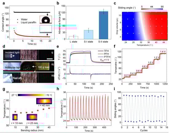
Figure 3.
Wetting, mechanical, and Joule heating characterization of the PTFH. (a) Contact angle of water and liquid paraffin droplets on the porous PVDF-HFP layer over time. (b) Adhesive force between water droplet and the PTFH surface under three conditions: L, S-I, and S-II. (c) Phase diagram showing water sliding angles based on surface temperatures and drop volumes. (d) Mechanical stability test of the TFH. Scale bar: 1 cm. (e) Temperature and gradient variations over time for different materials (TFH, PFH, and PTFH). VDC = 1 V. (f) Temperature evolution of the PTFH as VDC ranges from 1 to 1.4 V. (g) Steady-state temperature of the PTFH as a function of bending radius, with insets showing thermal infrared images at 10, 25, and 40 mm radii. Error bars, s.d. (n = 3). (h) Cyclic stability of PTFH’s Joule heating performance over 15 heating-cooling cycles at room temperature. (i) Variation of water SA on the PTFH as joule heating cycle numbers increase.
The key to controlling the paraffin layer’s phase transition on the PTFH is maintaining surface temperature. We studied TFH’s electro-thermal properties as the substrate for the PTFH. The results indicate that lower THF transparency increases heating rate and uniformity of surface temperature distribution (Figure S5 in the Supplementary Materials). This is due to higher CuNW density, reduced surface resistance, and dense fibers enabling rapid heat distribution. We chose TFH with 85% transmittance as the PTFH substrate for a balance of transparency and fast heating.
To ensure coating and tailoring of the TFH, the CuNWs on its surface must bond effectively with the supporting material. We tested the mechanical stability by attaching a TFH sample (85% transparency) with tape, applying a 100 g load, and then peeling off the tape. No copper nanofibers were peeled or damaged (Figure 3d), demonstrating strong adhesion between the CuNWs and the PDMS layer. This ensures the feasibility of subsequent CuNW coating with PVDF-HFP film and material processing, such as cutting and bending.
We tested the Joule thermal properties of TFH, PFH, and PTFH, as shown in Figure 3e. When the VDC is set at 1 V, PTFH and PFH exhibit similar Joule thermal properties to the TFH. This result indicates that the PVDF-HFP film coating and paraffin perfusion do not compromise the Joule thermal performance of the TFH. The maximum heating rate for these three materials can reach 25 °C/s. The steady-state temperatures of PTFH and PFH are slightly higher than that of the TFH because the surface of the CuNWs is covered with the PVDF-HFP film and paraffin, which reduces heat dissipation from the material surface.
The temperature rise curves of the PTFH surface under different voltages are displayed in Figure 3f. The surface temperature increases with VDC; at 0.2 V, the temperature rises by 5.4 °C, while at 1.4 V, it increases from 23.3 °C to 113.5 °C. Adjusting VDC allows for surface temperature control by Joule’s law. At just 0.5 V, the PTFH surface transitions from solid to liquid within 2 s. Figure 3g illustrates the material’s temperature changes at various angles, demonstrating excellent bending resistance (Figure S6, Video S1, Supplementary Materials). Figure 3h shows 15 periodic heating and cooling curves at 0.4 V, indicating rapid response and cyclic stability. Figure 3i confirms the material’s outstanding periodic stability for reversible droplet SA transitions under input voltage.
We investigated the transmittance of TFH, PFH, and PTFH. Coating the TFH (85% transmittance) with PVDF-HFP enhances light scattering due to its microporous surface structure, significantly reducing material transmittance [31]. The transmittance of PFH at 550 nm was only 29% (Figure S7, Supplementary Materials). After paraffin infusion, PTFH’s transmittance increased to 39% at room temperature. When a VDC is applied, Joule heating melts the paraffin layer, creating a molecularly smooth surface that enhances light transmittance to 89%. This property allows for practical observation of color changes in micro-biochemical reactions on the material’s surface.
3.3. Programmable Sliding Control of Single Droplets on the PTFH Surface
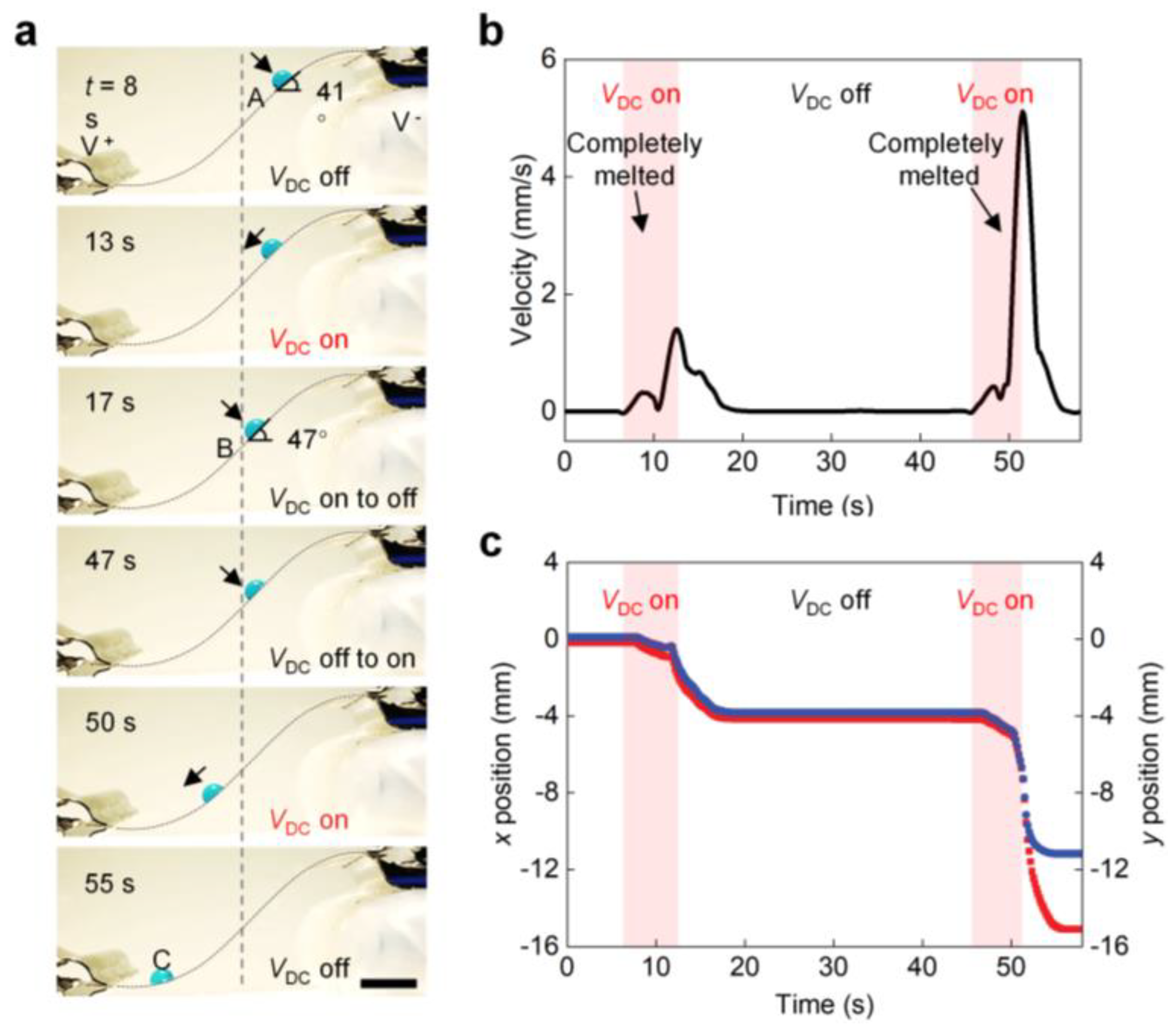
Figure 4a shows a droplet sliding along a highly curved S-shaped PTFH surface. At 0 s, the droplet is held in place at position A on the surface of the PTFH, and the tilt angle is 41°. When a VDC is applied, the paraffin on the material’s surface melts. After about two seconds, the droplet slides, and the rate of sliding increases with the increase of the bending angle. When VDC = 0, the sliding droplet slows down and stops at position B (tilting = 47°) within 1 s. The pinning of droplets results from forming a ring ridge around the droplet, which enhances the SA of the droplet. The droplet resumes moving and eventually reaches position C as the VDC is applied again (see Video S2, Part 1, Supplementary Materials). Figure 4b,c shows the droplet’s x- and y-axis displacement corresponding to Figure 4a along the s-shaped curved PTFH surface and the change curve of velocity with time.

Figure 4.
Programmable sliding control of single droplets on the PTFH surface. (a) Time-sequence images showing programmable control of droplet sliding on an inclined PTFH surface. Time is shown at the upper left of each panel. Scale bar: 5 mm. The time when VDC is applied is set as 0 s. (b) Variation of droplet movement velocity versus time in (a). (c) Variation of the droplet’s x-axis and y-axis displacement versus time in (a).
3.4. Programmable Droplet Actuation on Bioinspired Gradient PTFH Surface
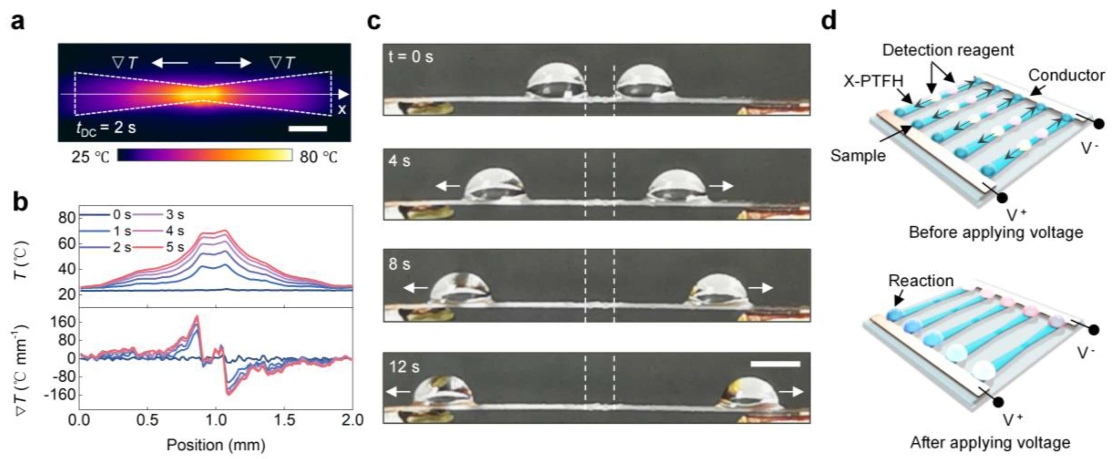
Cactus spines move droplets from tip to tail due to surface energy and curvature gradients [9]. Inspired by this, the V-PTFH was prepared by cutting (Figure 5a). Numerical simulations show potential and temperature distributions on the V-PTFH under VDC. Infrared imaging confirms that a resistance gradient at the narrow junction generates a temperature gradient under constant current. At 1 V, surface temperature is symmetrical, peaking at 80 °C at the link and dropping to 20 °C on the broadside, resulting in a gradient from tip to tail. The maximum gradient is 22 °C/mm (Figure 5b), aligning with the Laplace gradient. In Figure 5c, at 1 V, the phase transition layer melts due to increased temperature, changing the droplet’s wetting state from high-adhesion S-II to low-adhesion L, allowing droplet movement to the right under Laplace pressure and the temperature gradients (see Video S3). Figure 5d shows the merging red and blue droplets on the V-PTFH under voltage, highlighting its potential in microreactors.
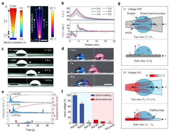
Figure 5.
Programmable droplet actuation on a bioinspired gradient PTFH surface. (a) (i) Simulated electric potential distribution on the V-PTFH; (ii) Infrared image of Joule heating on the V-PTFH (VDC = 1 V). Scale bar: 5 mm. (b) Temperature and gradient profiles along the testing line (x-direction) at various times. (c) Horizontal actuation of an 8 μL water droplet on the V-PTFH. Scale bar: 3 mm. The white dotted lines indicate the initial position of the droplet, and the white arrows show its movement direction. (d) Coalescence of two water droplets on the V-PTFH. Scale bar: 3 mm. The white dotted lines indicate the initial position of the droplet, and the white arrow shows the direction of its movement. (e) Droplet velocity and displacement over time on V-SLIPS and V-PTFH. Red and blue triangles mark the start and end points, respectively. (f) Input voltage for droplet manipulation on the PTFH compared to earlier studies. The orange star indicates successful actuation. (g) Mechanism of programmable droplet actuation on the V-PTFH. θA and θB are the contact angles on sides A and B. γsa, γls, γla, γoa, and γol are the surface tensions of solid-gas, liquid-solid, liquid-gas, oil-gas, and oil-liquid interfaces, respectively.
To highlight the advantages of the V-PTFH in laterally controlled droplet transport, we compare the PTFH with a traditional V-shaped SLIPS surface (with a lubrication layer of liquid paraffin and a porous layer made of PVDF-HFP, referred to as SLIPS). As shown in Figure 5e, under the influence of the Laplace force, the maximum transmission speed of droplets on the V-SLIPS surface can reach 2.2 mm/s, with a maximum transmission distance of 10.1 mm. In contrast, the maximum speed of droplets on the V-PTFH surface is ~1.9 mm/s. However, droplets can be transmitted over a longer distance (13.94 mm), and the starting and ending points of droplet transmission can be controlled by adjusting the input VDC. This indicates that PTFH surfaces can achieve programmable control of liquid droplets compared to ordinary SLIPS surfaces. Additionally, programmable droplet actuation on the PTFH requires only 1 V, which is significantly lower than previous reports (Figure 5f) [22,23,24,25,26].
Figure 5g illustrates the droplet’s programmable driving mechanism on the PTFH’s surface. Droplet’s motion on the V-PTFH arises from the driving force and viscous resistance interaction. The driving force includes the Laplace pressure force (FL) from the surface geometry and the Marangoni force (FM) from the temperature gradient. Viscous resistance is hydrodynamic resistance (FH). Due to the wedge shape of the V-PTFH, the Laplace pressure (FL) along the x-axis moves the droplet from the smaller wettable footprint (left) to the larger one (right). The FL is expressed as follows [32]:
where α is half the wedge angle, and A and B are constants for a given volume of droplets. When VDC = 0, FL exists on the surface of the PTFH, but FL = FH due to contact line pinning from the rough surface microstructure, preventing droplet movement. When VDC is applied, the PTFH surface temperature increases, transforming the liquid–solid interface between droplets and PTFH into a liquid–liquid interface. Heat transfer between the PTFH ∇T and droplets creates a sharp ∇T across the droplet. The spatial variation of surface tension from generates FM, described as follows [33,34]:
FL = Aα + B,
The force direction is toward the lower temperature side of the droplet. The term dγla/dT describes the surface tension–temperature relationship at the liquid–gas interface, while dT/dx indicates the surface temperature gradient, with x representing the droplet’s movement direction. The hydrodynamic resistance of the droplet (FH) opposes its movement. FH includes the viscous force within the droplet and that from the annular ridge formed by the paraffin coating at the droplet’s base. This can be expressed as follows [33]:
where β is a numerical factor, μo is the paraffin viscosity, μl is the viscosity of droplets, and v is the velocity of the droplet movement. According to Equation (3), FH increases with droplet velocity.
According to Equations (1)–(3) and experiments, at the start of droplet actuation, FM + FL > FH, so the droplet accelerates. When FM + FL = FH, it moves steadily. If VDC stops, paraffin solidifies on the PTFH surface as the temperature drops. With increasing FH, the droplet slows down and stops when FM + FL = 0.
3.5. Programmable Control of Multi-Droplets on the Bioinspired PTFH Surface
To control multiple droplets on the same surface, we prepared the X-PTFH by clipping. The infrared image in Figure 6a confirms our hypothesis. In Figure 6b, at VDC = 1.5 V, the X-PTFH surface temperature shows symmetrical distribution. The highest temperature reaches 67 °C at the link, while the lowest temperature is 30 °C on wider sides, creating a temperature gradient of up to 12 °C/mm in the opposite direction. This combines temperature and Laplace gradients on the X-PTFH surface. In Figure 6c, at VDC = 1.5 V, two droplets move at 2.3 mm/s toward both sides of the X-PTFH, enabling programmable control of multiple droplets under a single stimulus (see Video S4, Supplementary Materials). Based on these characteristics, we designed a microreactor device for batch reactions of various droplets, as shown in Figure 6d. Additionally, we performed systematic tests on the long-term stability of the PTFH. The results indicated that, using the V-PTFH as an example, its performance did not exhibit significant attenuation after 300 droplet-driven experiments, demonstrating its excellent durability (Figure S8, Supplementary Materials). As a heat-driven technology, the evaporation of droplets can be reduced by sealing the system to minimize evaporation or using liquids less prone to evaporation, such as ionic liquids, for driving [35].

Figure 6.
Programmable control of multi-droplets on the bioinspired PTFH surface. (a) Representative infrared image of the Joule heating response of an X-PTFH. VDC = 1.5 V. Scale bar: 3 mm. (b) Temporal temperature and temperature gradient profiles extracted from the infrared images along the testing line (x-direction) in panel c at various times. (c) Time-sequence images showing the bidirectional horizontal actuation of water droplets (8 μL) on an X-PTFH. The white dotted lines indicate the initial positions of the droplets, and the white arrows show their movement directions. VDC = 1.5 V. Scale bar: 3 mm. (d) Schematic illustration of the design of a microreactor device capable of conducting panel testing.
4. Conclusions
In conclusion, we introduce a novel bio-inspired phase-change transparent flexible heater (PTFH). By embedding a self-junctioned nanometal network within a porous gel matrix infused with phase-change material, microdroplets’ programmable and non-contact mobility control can be achieved using ultralow input voltage. Mimicking the unique geometric gradient structure found on the surfaces of living organisms, the PTFH can be bent or clipped to enable precise and programmable control of droplet mobility across various configurations and dimensions. This innovation offers a new paradigm for designing droplet-controlled surfaces, with potential applications in microreactors, mass transfer systems, microengines, and smart windows.
Supplementary Materials
The following supporting information can be downloaded at: https://www.mdpi.com/article/10.3390/lubricants13060272/s1, Figure S1: Schematic procedure for preparing the PTFH; Figure S2: Influence of plating time on CuNWs; Figure S3: Diameter distribution of PAN nanofibers and CuNWs; Figure S4: EDS results of the CuNWs; Figure S5: Transmittance and heat distribution of the TFH; Figure S6: Time-sequence infrared images of the bending and stretching process of the PTFH; Figure S7: UV–Vis spectra of TFH, PFH, PTFH (VDC off), and PTFH (VDC on) in the visible light range; Figure S8: Durability analysis of PTFH performance; Video S1: Infrared video of the bending and stretching process of the PTFH under an applied voltage; Video S2: Programmable sliding control of single droplets on the PTFH surface; Video S3: Programmable droplet actuation on the bioinspired gradient PTFH surface; Video S4: Programmable control of multi-droplets on the bioinspired PTFH surface.
Author Contributions
Conceptualization, methodology, software, validation, formal analysis, investigation, resources, data curation, writing—original draft preparation, and writing—review, L.S. and C.G.; editing, L.S., C.G., and W.L.; supervision, C.G. and W.L.; project administration, C.G. and W.L.; funding acquisition, L.S. and C.G. All authors have read and agreed to the published version of the manuscript.
Funding
This work was supported by the High-level Talent Introduction Research Initiation Grant Program of Taizhou Institute of Vocational Technology (Grant No. 2025GCC10, No.2025GCC04).
Data Availability Statement
The original contributions presented in this study are included in the article/supplementary material. Further inquiries can be directed to the corresponding author.
Conflicts of Interest
The authors declare no conflicts of interest.
References
- Liu, M.; Wang, S.; Jiang, L. Nature-inspired superwettability systems. Nat. Rev. Mater. 2017, 2, 17036. [Google Scholar] [CrossRef]
- Zhang, T.; Liu, C.; Li, X.; Guo, F.; Zhu, K. Fabrication of a composite groove array surface with gradient wettability which delivers enhanced lubrication performance. Lubricants 2025, 13, 193. [Google Scholar] [CrossRef]
- Zhang, P.; Guo, Z. Robust anti-icing slippery liquid-infused porous surfaces inspired by nature: A review. Mater. Today. Phys. 2024, 46, 101478. [Google Scholar] [CrossRef]
- Xu, W.; Zheng, H.; Liu, Y.; Zhou, X.; Wang, Z. A droplet-based electricity generator with high instantaneous power density. Nature 2020, 578, 392–396. [Google Scholar] [CrossRef] [PubMed]
- Li, H.; Shkolyar, E.; Wang, J.; Conti, S.; Pao, A.C.; Liao, J.C.; Wong, T.-S.; Wong, P.K. SLIPS-LAB-A bioinspired bioanalysis system for metabolic evaluation of urinary stone disease. Sci. Adv. 2020, 6, eaba8535. [Google Scholar] [CrossRef]
- Wang, X.; Zhuang, Z.; Yao, L.X. Droplet manipulation on bioinspired slippery surfaces: From design principle to biomedical applications. Small Methods 2024, 8, 2300253. [Google Scholar] [CrossRef]
- Li, X.; Wang, J.; Yi, G.; Teong, S.P.; Chan, S.P.; Zhang, Y. From waste plastic to artificial lotus leaf: Upcycling waste polypropylene to superhydrophobic spheres with hierarchical micro/nanostructure. Appl. Catal. B-Environ. Energy 2024, 342, 123378. [Google Scholar] [CrossRef]
- Chen, H.; Zhang, P.; Zhang, L.; Liu, H.; Jiang, Y.; Zhang, D.; Han, Z.; Jiang, L. Continuous directional water transport on the peristome surface of Nepenthes alata. Nature 2016, 532, 85–89. [Google Scholar] [CrossRef]
- Ju, J.; Bai, H.; Zheng, Y.; Zhao, T.; Fang, R.; Jiang, L. A multi-structural and multi-functional integrated fog collection system in cactus. Nat. Commun. 2012, 3, 1247. [Google Scholar] [CrossRef]
- Liu, X.; Gao, M.; Li, B.; Liu, R.; Chong, Z.; Gu, Z.; Zhou, K. Bioinspired capillary transistors. Adv. Mater. 2024, 36, 2310797. [Google Scholar] [CrossRef]
- Wang, Z.; Jiang, L.; Heng, L. Liquid adhesion regulation on bioinspired slippery surfaces: From theory to application. ACS Nano 2025, 19, 13549–13566. [Google Scholar] [CrossRef] [PubMed]
- Wong, T.-S.; Kang, S.H.; Tang, S.K.; Smythe, E.J.; Hatton, B.D.; Grinthal, A.; Aizenberg, J. Bioinspired self-repairing slippery surfaces with pressure-stable omniphobicity. Nature 2011, 477, 443–447. [Google Scholar] [CrossRef]
- Ma, S.; Liu, L.; Zhao, W.; Li, R.; Zhao, X.; Zhang, Y.; Yu, B.; Liu, Y.; Zhou, F. Earthworm inspired lubricant self-pumping hydrogel with sustained lubricity at high loading. Nat. Commun. 2025, 16, 398. [Google Scholar] [CrossRef]
- Li, J.; Ueda, E.; Paulssen, D.; Levkin, P.A. Slippery lubricant–infused surfaces: Properties and emerging applications. Adv. Funct. Mater. 2019, 29, 1802317. [Google Scholar] [CrossRef]
- Lou, X.; Huang, Y.; Yang, X.; Zhu, H.; Heng, L.; Xia, F. External stimuli responsive liquid–infused surfaces switching between slippery and nonslippery states: Fabrications and applications. Adv. Funct. Mater. 2020, 30, 1901130. [Google Scholar] [CrossRef]
- Tian, L.; Dou, H.; Shao, Y.; Yi, Y.; Fu, X.; Zhao, J.; Fan, Y.; Ming, W.; Ren, L. Magnetically controlled super-wetting surface switching between ultra-low and ultra-high droplet adhesion. Chem. Eng. J. 2023, 456, 141093. [Google Scholar] [CrossRef]
- Wang, W.; Timonen, J.V.; Carlson, A.; Drotlef, D.-M.; Zhang, C.T.; Kolle, S.; Grinthal, A.; Wong, T.-S.; Hatton, B.; Kang, S.H. Multifunctional ferrofluid-infused surfaces with reconfigurable multiscale topography. Nature 2018, 559, 77–82. [Google Scholar] [CrossRef] [PubMed]
- Yao, Y.; Zhou, J.; Zhu, S.; Peng, Y.; Yong, J.; Wu, D. Thermo-induced biomimetic switchable slippery interfaces with strong dual-phase adhesion via femtosecond laser fabrication. Nano Lett. 2025, 25, 4252–4259. [Google Scholar] [CrossRef]
- Wang, L.; Zhang, C.; Zhang, Y.; Shen, C.; Xin, Z.; Wei, Z. Bionic Fluorine-Free Multifunctional Photothermal Surface for Anti/de/Driving-Icing and Droplet Manipulation. Adv. Sci. 2024, 11, 2409631. [Google Scholar] [CrossRef]
- Sun, L.; Bian, F.; Wang, Y.; Wang, Y.; Zhang, X.; Zhao, Y. Bioinspired programmable wettability arrays for droplets manipulation. Proc. Natl. Acad. Sci. USA 2020, 117, 4527–4532. [Google Scholar] [CrossRef]
- Chen, C.; Huang, Z.; Zhu, S.; Liu, B.; Li, J.; Hu, Y.; Wu, D.; Chu, J. In situ electric–induced switchable transparency and wettability on laser–ablated bioinspired paraffin–impregnated slippery surfaces. Adv. Sci. 2021, 8, 2100701. [Google Scholar] [CrossRef] [PubMed]
- Lee, J.; Moon, H.; Fowler, J.; Schoellhammer, T.; Kim, C.-J.J.S. Electrowetting and electrowetting-on-dielectric for microscale liquid handling. Sens. Actuat. A-Phys. 2002, 95, 259–268. [Google Scholar] [CrossRef]
- Ko, H.; Lee, J.; Kim, Y.; Lee, B.; Jung, C.-H.; Choi, J.-H.; Kwon, O.-S.; Shin, K. Active digital microfluidic paper chips with inkjet-printed patterned electrodes. Adv. Mater. 2014, 26, 2335–2340. [Google Scholar] [CrossRef] [PubMed]
- Li, J.; Ha, N.S.; Liu, T.L.; van Dam, R.M.; ‘CJ’Kim, C.-J. Ionic-surfactant-mediated electro-dewetting for digital microfluidics. Nature 2019, 572, 507–510. [Google Scholar] [CrossRef]
- Chen, C.; Huang, Z.; Jiao, Y.; Shi, L.-A.; Zhang, Y.; Li, J.; Li, C.; Lv, X.; Wu, S.; Hu, Y. In situ reversible control between sliding and pinning for diverse liquids under ultra-low voltage. ACS Nano 2019, 13, 5742–5752. [Google Scholar] [CrossRef]
- Wang, J.; Gao, W.; Zhang, H.; Zou, M.; Chen, Y.; Zhao, Y. Programmable wettability on photocontrolled graphene film. Sci. Adv. 2018, 4, eaat7392. [Google Scholar] [CrossRef]
- Cunha, I.; Ferreira, S.H.; Martins, J.; Fortunato, E.; Gaspar, D.; Martins, R.; Pereira, L. Foldable and recyclable iontronic cellulose nanopaper for low--power paper electronics. Adv. Sustain. Sys. 2022, 6, 2200177. [Google Scholar] [CrossRef]
- Mishra, A.; Wallin, T.; Pan, W.; Xu, A.; Wang, K.; Giannelis, E.; Mazzolai, B.; Shepherd, R. Autonomic perspiration in 3D-printed hydrogel actuators. Sci. Robot. 2020, 5, eaat3918. [Google Scholar] [CrossRef]
- Adams, M.J.; Briscoe, B.J.; Johnson, S.A. Friction and lubrication of human skin. Tribol. Lett. 2007, 26, 239–253. [Google Scholar] [CrossRef]
- An, S.; Jo, H.S.; Kim, D.Y.; Lee, H.J.; Ju, B.K.; Al-Deyab, S.S.; Ahn, J.H.; Qin, Y.; Swihart, M.T.; Yarin, A.L.; et al. Self-junctioned copper nanofiber transparent flexible conducting film via electrospinning and electroplating. Adv. Mater. 2016, 28, 7149–7154. [Google Scholar] [CrossRef]
- Okada, I.; Shiratori, S. High-transparency, self-standable gel-SLIPS fabricated by a facile nanoscale phase separation. ACS Appl. Mater. Interfaces 2014, 6, 1502–1508. [Google Scholar] [CrossRef] [PubMed]
- Lorenceau, E.; Quéré, D. Drops on a conical wire. J. Fluid. Mech. 2004, 510, 29–45. [Google Scholar] [CrossRef]
- Bjelobrk, N.; Girard, H.-L.; Bengaluru Subramanyam, S.; Kwon, H.-M.; Quéré, D.; Varanasi, K.K. Thermocapillary motion on lubricant-impregnated surfaces. Phys. Rev. Fluids 2016, 1, 063902. [Google Scholar] [CrossRef]
- Brzoska, J.; Brochard-Wyart, F.; Rondelez, F.J.L. Motions of droplets on hydrophobic model surfaces induced by thermal gradients. Langmuir 1993, 9, 2220–2224. [Google Scholar] [CrossRef]
- Zhang, J.; Zhang, K.; Wang, W.; Shahzad, A.; Cheng, Y.; Cai, G. Permeation by electrowetting actuation: Revealing the prospect of a micro-valve based on ionic liquid. J. Colloid Interface Sci. 2022, 608, 114–119. [Google Scholar] [CrossRef]


Disclaimer/Publisher’s Note: The statements, opinions and data contained in all publications are solely those of the individual author(s) and contributor(s) and not of MDPI and/or the editor(s). MDPI and/or the editor(s) disclaim responsibility for any injury to people or property resulting from any ideas, methods, instructions or products referred to in the content. |
© 2025 by the authors. Licensee MDPI, Basel, Switzerland. This article is an open access article distributed under the terms and conditions of the Creative Commons Attribution (CC BY) license (https://creativecommons.org/licenses/by/4.0/).