1. Introduction
In the era of modern mechanical manufacturing, rotating machinery is developing toward higher speeds and heavier loads. This trend is especially evident in industries such as automotive, shipbuilding, and aerospace. In these fields, the application of rotating machinery is becoming increasingly widespread. Support bearings in rotating components are particularly critical for ensuring stable operation. With the recent progress in understanding the properties of supercritical carbon dioxide (S-CO2), this study selected a four-oil-cavity S-CO2 hydrodynamic journal bearing as the research object. S-CO2 is a special working fluid that exhibits both gas-like and liquid-like properties. It offers advantages such as low weight, high density, cost-effectiveness, and energy efficiency. These features make it suitable for devices like turbines and help improve power output.
Compared with conventional bearings, this bearing is more suitable for use with S-CO2. Its structural design and material selection are optimized to meet the requirements of supercritical working fluids. The four oil cavities help generate a uniform oil film pressure distribution during operation. They can also adjust the pressure dynamically according to the journal’s loading conditions. The cooperative function of the cavities allows the journal to remain in a relatively stable position.
At present, research on S-CO2 hydrodynamic journal bearings is gradually advancing. Several viewpoints and findings have been proposed by scholars both domestically and internationally.
In 1854, the concept of gas lubrication was first introduced by the French researcher Gustav Adolph Him. At the same time, fluid mechanics expert O. Reynolds proposed the slot-restricted hypothesis to simplify the Navier–Stokes equations. This simplification enabled the integration of hydrodynamic principles into thin film lubrication analysis. H.C. Kocman et al. evaluated [
1] various algorithmic strategies for optimizing hydrodynamic bearing performance, and finally recommended the PSWM algorithm as the best default choice due to its ease of use and minimal sensitivity to parameter settings. Shahin et al. [
2] constructed a test bench to evaluate the steady-state performance of journal bearings under varying design parameters. They also conducted dynamic analyses using computational fluid dynamics (CFD), which showed that the bearings exhibited lower elastic strain and deformation within an aspect ratio range of 0.25–0.50. Chen et al. [
3] investigated the tribodynamic behavior of water-lubricated bearings by studying parameters such as clearance ratio, surface roughness, and length-to-diameter ratio. Their parametric study systematically assessed the effects on friction coefficient, minimum film thickness, and load-carrying capacity. Dhandhe et al. [
4] used fluid–structure interaction (FSI) methods to analyze journal bearings under cavitation and elastic deformation, focusing on oil film pressure variation. Snyder et al. [
5] used an alternative method based on CFD with a moving boundary to predict the dynamic coefficients of slider bearings, and compared the results with the commonly used perturbed Reynolds equation model. Prasad et al. [
6] applied this method to evaluating journal bearings with different L/D ratios and eccentricities. Liang et al. [
7] developed a deterministic mixed lubrication model to evaluate the effect of surface roughness on water-lubricated thrust bearings with elastic support and multi-layer soft materials. Lin et al. [
8] proposed a transient CFD–FSI method, considering thermal and cavitation effects, for rotor-bearing systems. Yu et al. [
9] analyzed oil film stability in dual-cavity hydrostatic bearings and validated results through experiments. Rasep et al. [
10] explored the use of vegetable oils in journal bearings. They examined the impact of geometry and texture, emphasizing the potential of plant-based lubricants. Conboy et al. [
11] proposed a new wedge-shaped structure for static pressure thrust bearings. This was for high-speed and heavy-load conditions. They studied the oil film pressure distribution. Hydrodynamic pressure was used to compensate for the lack of static pressure bearing capacity. Rowe et al. [
11] compared traditional tapered static pressure bearings with three-groove and four-groove designs. This was under high-speed operating conditions. The results showed that narrow grooves provided better radial load support than long and wide grooves.
The S-CO
2 thermodynamic cycle offers higher thermal efficiency than traditional steam Rankine cycles, thereby reducing both fuel consumption and greenhouse gas emissions. This advantage has led to its widespread adoption in modern energy systems, including concentrated solar power plants [
12,
13] and nuclear power facilities [
14]. Zhang et al. [
15] systematically examined the effects of flow regimes on the flow field and sealing performance of S-CO
2 dry gas seals. They also developed a reliable method for characterizing flow regimes in S-CO
2 gas flows. Yi et al. [
16,
17] developed an integrated theoretical model that incorporated inertial effects, revealing their impact on the static and dynamic characteristics of S-CO
2 tilting pad bearings, along with a novel thermo-elastohydrodynamic mixed lubrication model that considered thermal–mechanical coupling effects. To predict the lubrication behavior of S-CO
2 tilting pad bearings more accurately, Li et al. [
18] conducted a numerical study on the static performance of hydrostatic thrust bearings lubricated with CO
2. Their results indicated a strong dependency on film thickness, with the load capacity increasing exponentially as the film thickness decreased. Bi et al. [
19] introduced a thermal balance method for high-speed S-CO
2 tilting pad bearings, showing speed-dependent thermal effects. Zhu et al. [
20] studied S-CO
2-lubricated radial bearings under startup and high-speed conditions and designed a hybrid ceramic bearing for the Brayton cycle. Qin et al. [
21,
22] used CFD simulations to analyze the static characteristics of S-CO
2-lubricated gas foil thrust bearings (GFTBs). Mehdi et al. [
23] developed a four-oil cavity radial hydrodynamic journal bearing model for S-CO
2 analysis. They studied the maximum oil film pressure and load capacity. This was at high rotational speeds of 60 krpm to 100 krpm. Ertas et al. [
24,
25] proposed a new fluid–structure interaction model for S-CO
2 thrust bearings. They performed rotational experiments at 10 krpm. The inlet pressure was 2.52 MPa. The results revealed a nonlinear relationship between thrust load and film gap.
Most existing research and literature investigating the influence of bearing parameter variations on load-carrying capacity and frictional characteristics primarily employ conventional lubrication media. In contrast, studies on S-CO2 bearings have focused mainly on hydrostatic bearing configurations. Research concerning the tribodynamic behavior of dynamically lubricated bearings using S-CO2, particularly under ultra-high-speed operating conditions, remains limited. In particular, there is a lack of systematic analysis on how variations in bearing geometry and operational parameters influence the hydrodynamic performance.
To fill this research gap, this study used an FSI method. The method combined CFD and structural analysis in ANSYS Workbench. A parametric analysis was performed under ultra-high-speed conditions. The effects of radial clearance (0.1–0.5 mm), eccentricity ratio (0.1–0.5), inlet diameter (0.5–2.5 mm), and oil cavity geometry (six types) were investigated. Three key performance indicators were considered: maximum film pressure, load capacity, and friction coefficient. The results offer design guidance for S-CO2-lubricated bearings in high-speed rotating machines.
3. Computational Model and Simulation Conditions
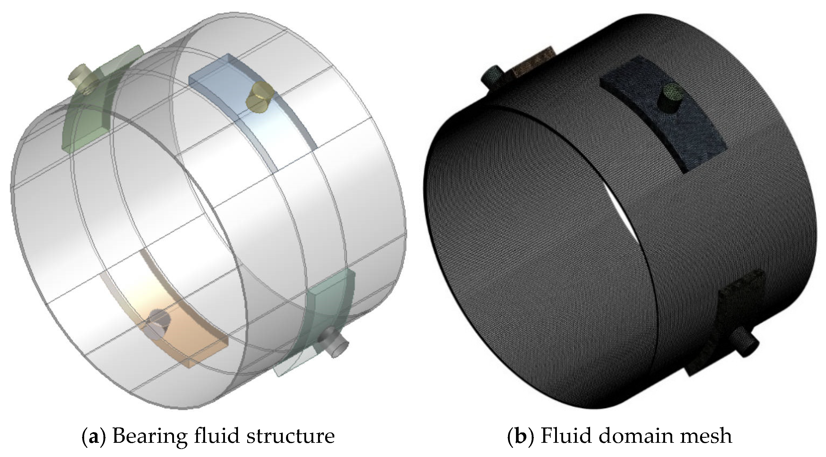
The subject of this study was a conventional four-pocket hydrodynamic journal bearing. The bearing was designed with four inlet ports, and the bearing sleeve contained four equally sized lubricant reservoirs. These reservoirs served to store the lubrication medium. The structural parameters of the bearing are listed in
Table 1. Based on the parameters in
Table 1, a three-dimensional model of the lubricant film was constructed using Design Modeler. A schematic diagram of the radial hydrodynamic bearing structure is shown in
Figure 2.
To address potential mesh instability caused by the thin fluid film, the bearing fluid domain was divided into multiple regions, as shown in
Figure 3a. A sweeping mesh strategy was applied in the lubricating oil film contact region. The total number of partitions was 120, with 15 internal layers. In the cavitation region, mesh refinement increased the partition count to 150 to better capture cavitation effects. Local refinement was performed at the inlet, outlet, and zones of sudden velocity gradient to ensure accuracy. The minimum element size was 2 × 10
−5 m, the maximum was 4 × 10
−5 m, and the minimum curvature element size was 2 × 10
−7 m. The overall mesh quality reached 0.9, meeting accuracy requirements and guaranteeing convergence. The mesh distribution is shown in
Figure 3b.
In FLUENT, to accelerate computation, 50 solver threads were used on the server for a steady-state simulation. The cavitation model uses the Mixture model to solve the Schnerr–Sauer method. A coupled pressure-based solver was selected for its suitability in fluid–structure coupling and improved accuracy. A first-order discretization scheme was adopted. Convergence was declared when the residual of each equation fell below 1 × 10⁻⁴. The boundary conditions were defined as follows:
(1) The four inlet ports were set as pressure inlets, with an inlet pressure of 8 Mpa. (2) The two ends of the bearing were set as pressure outlets, with the outlet pressure defined as standard atmospheric pressure. (3) The inner surface was specified as a rotating wall, while the outer surface was treated as a stationary wall. (4) The inlet and outlet faces, outer wall, and inner rotating surface of the hydrodynamic bearing were all set to a constant temperature of 320 K to ensure lubrication under S-CO2 conditions. The NIST Real Gas model based on the REFPROP database was used to account for the nonlinear physical properties of CO2. (5) The rotational speed of the inner surface under working conditions was set to 50,000 rpm. (6) Given the high Reynolds number within the bearing, the standard k-ε turbulence model was adopted. The solution algorithm was configured using the SIMPLEC segregated scheme. This bearing is intended for turbine rotating components. Under high-speed, heavy-load conditions, the inner surface acts as the rotating member. To maintain simulation fidelity, the model temperature was held constant at 320 K. The inlet pressure was set to the supercritical CO2 critical pressure to ensure internal pressure. Inlet and outlet pressures were arranged in accordance with hydrodynamic lubrication principles.
4. Grid Independence Verification and Model Validation
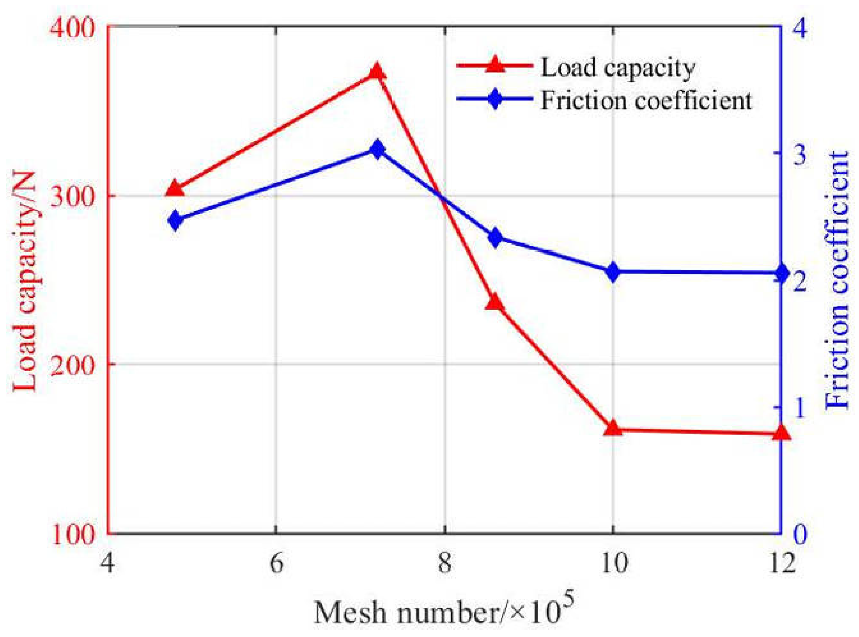
Due to the extremely small lubricant radial clearance in this model, a mesh independence verification was necessary to minimize solution error caused by mesh density and to reduce computational cost. The initial conditions were set as follows: eccentricity ratio of 0.5, inlet diameter of 2 mm, radial clearance of 0.3 mm, and oil pocket geometry defined by an axial width of 5 mm and a pocket angle of 45 radians. Mesh sizes of 480,000; 560,000; 720,000; 1,000,000; and 1,200,000 elements were tested, as shown in
Table 2 and
Figure 4. Error analysis was performed using load capacity as the metric. An error within 5% is generally deemed to indicate mesh independence. The verification results showed that the errors between adjacent mesh sizes of 480,000; 720,000; 860,000; 1,000,000; and 1,200,000 elements were 19.6%, 34.5%, 31.6%, and 1.9%, respectively. When the mesh size exceeded 1,000,000 elements, the variation in oil film load capacity became negligible. Considering the trade-off between accuracy and computational cost, a mesh size of 1,000,000 elements was adopted in this study.
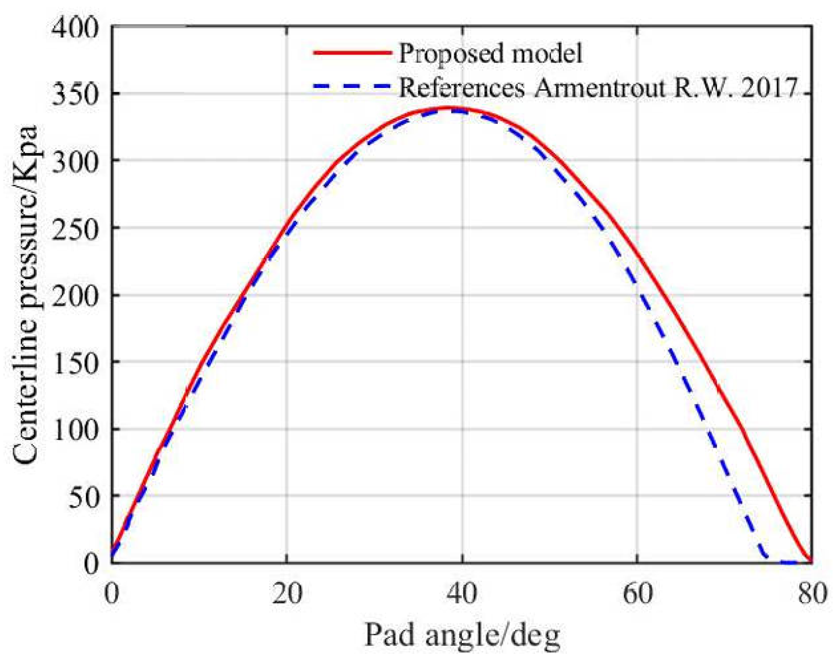
To ensure the accuracy of the computational model, the water-lubricated tilting-pad bearing model from reference [
27] was used as a comparison. The modeling and meshing methods from the literature were adopted for the analysis of the computational model. At a pad angle of 72°, the maximum pressure difference was 5.7%, as shown in
Figure 5. The error stemmed from inconsistent turbulence models. A k-ε solver was applied here, while the reference study used a Navier–Stokes solver. Moreover, the lower rotational speed in the reference led to low-Reynolds-number flow, where the k-ε model had reduced predictive accuracy. This caused the film pressure discrepancy. The k-ε model is better suited for high-speed characteristic analysis. Both solutions account for turbulence effects while neglecting fluid inertia effects. The overall analysis solution was consistent with the CFD solution, thereby validating the correctness of the computational model used in this study.
5. Results and Discussion
Under the above boundary conditions and with the computational model held constant, this study mainly investigated the effects of inlet diameter, eccentricity, radial clearance, and oil pocket dimensions on the maximum oil film pressure distribution, bearing deformation, load capacity, and friction coefficient. The following parameters were set: (1) inlet diameters: 0.5 mm, 1 mm, 1.5 mm, 2 mm, and 2.5 mm; (2) eccentricities: 0.1, 0.2, 0.3, 0.4, and 0.5; (3) radial clearance: 0.1 mm, 0.2 mm, 0.3 mm, 0.4 mm, and 0.5 mm; (4) oil pocket dimensions (axial width in mm × oil pocket angle in rad): 5 × 45, 7 × 45, 9 × 45, 5 × 60, 7 × 60, and 9 × 60, The calculated results were as follows:
5.1. Effect of Inlet Diameter
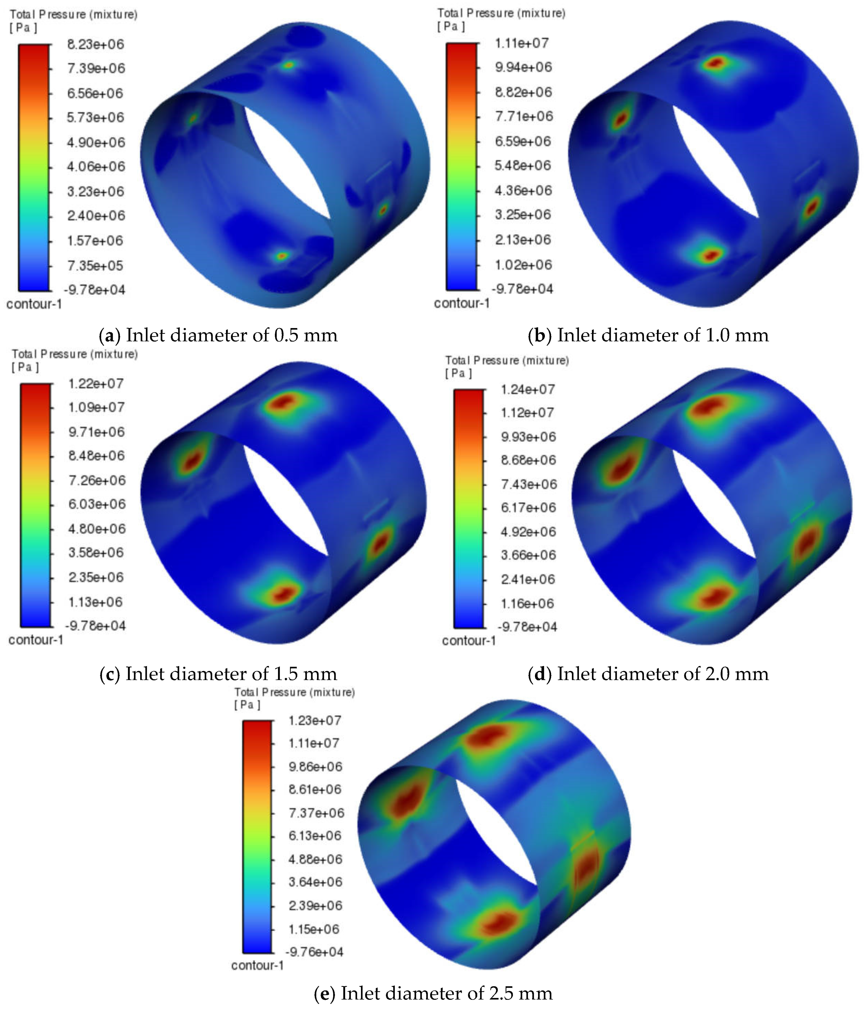
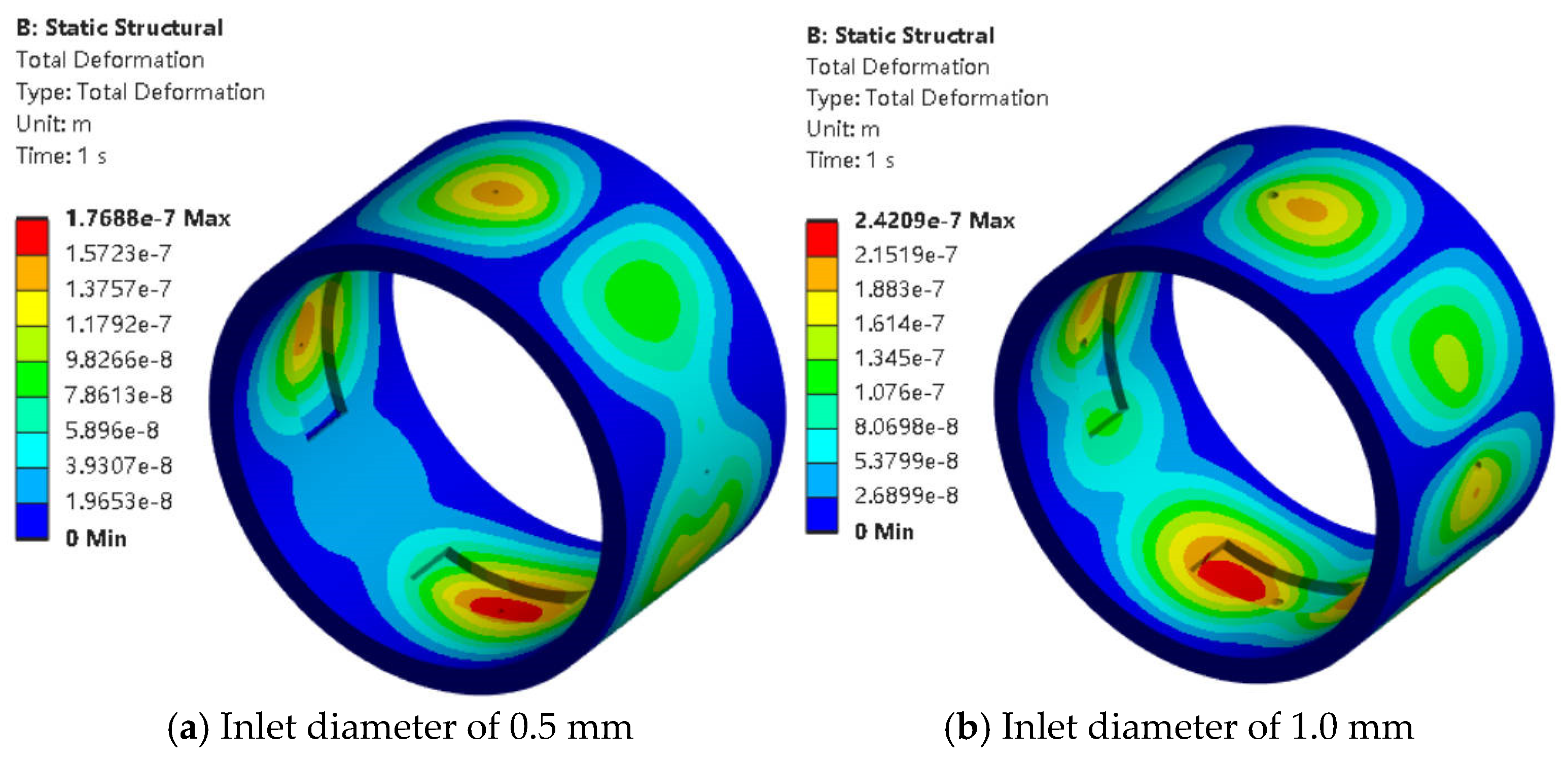
When the eccentricity was 0.5, the radial clearance was 0.3 mm, and the oil pocket dimensions (axial width in mm × pocket angle in rad) were 5 × 45. The oil film pressure distribution and bearing deformation regions under different inlet diameters are shown in
Figure 6 and
Figure 7.
As shown in
Figure 6 and
Figure 7, these negative pressure zones were located near the inlet regions and were related to the direction of rotation. This was mainly caused by the hydrodynamic effect generated by high-speed rotation. As the inlet diameter increased (
Figure 6a–e), the area of the negative pressure zone gradually decreased. Meanwhile, the negative pressure became more pronounced and was mainly concentrated near the upper and lower inlet ports. When the inlet diameter was 0.5 mm (
Figure 6a), it was too small for the lubricant to fully enter the oil chamber, so the negative pressure appeared on both sides of the inlet. When the inlet diameter was less than 1.5 mm (
Figure 7a,b), the maximum deformation occurred near the bottom oil chamber. When the inlet diameter reached 1.5 mm or more (
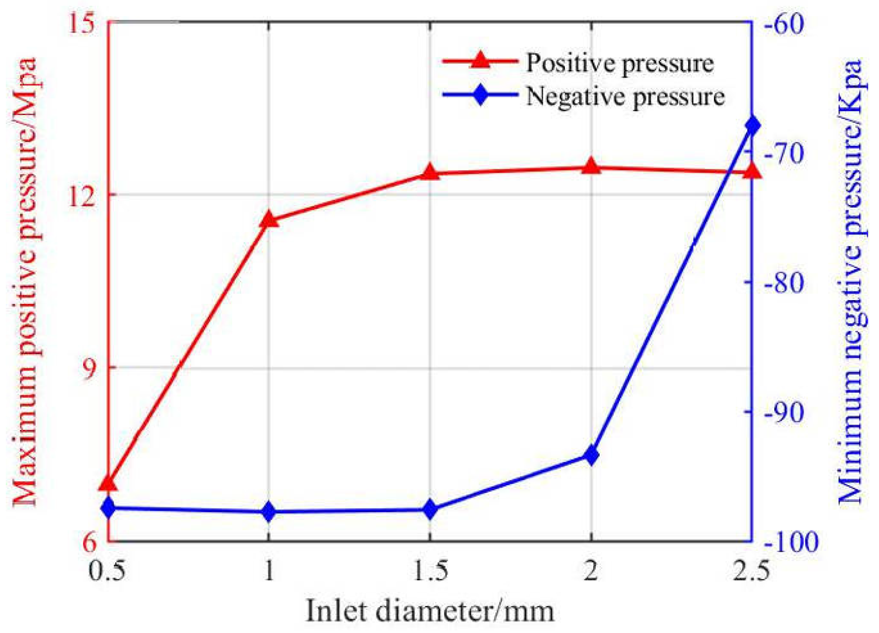
Figure 7c–e), the main deformation area shifted to the right side near the inlet. The variation trends of peak oil film pressure, load capacity, and friction coefficient as functions of inlet diameter from 0.5 mm to 2.5 mm are illustrated in
Figure 8 and
Figure 9.
As shown in
Figure 8 and
Figure 9, with increasing inlet diameter, both the maximum and minimum oil film pressures increased. When the inlet diameter ranged from 0.5 mm to 1.0 mm, the positive pressure increased significantly, surging sharply from 6.98 Mpa to 11.6 Mpa. This is because at 0.5 mm, the small inlet size limited the full entry of supercritical CO
2, resulting in lower positive pressure. When the diameter increased from 2.0 mm to 2.5 mm, the negative pressure rose significantly from −93.4 Kpa to −67.9 Kpa, indicating that enlarging the inlet reduced cavitation effects. When the inlet diameter ranged from 1.0 mm to 2.5 mm, the load capacity increased proportionally with the inlet diameter. In practical applications, excessively large inlet diameters may compromise oil film integrity and face constraints from sealing devices. The friction coefficient showed a rising-then-falling trend, reaching its maximum at 2.0 mm, with a value of 2. This phenomenon resulted from the sudden increase in negative pressure, which alleviated cavitation effects. The bearing deformation increased with the inlet diameter, showing a sharp rise from 4.95 × 10
−7 m to 2.41 × 10
−6 m between 1.5 mm and 2.0 mm.
Increasing the inlet diameter increased the oil film pressure and load capacity while reducing cavitation effects, but it also led to greater bearing deformation.
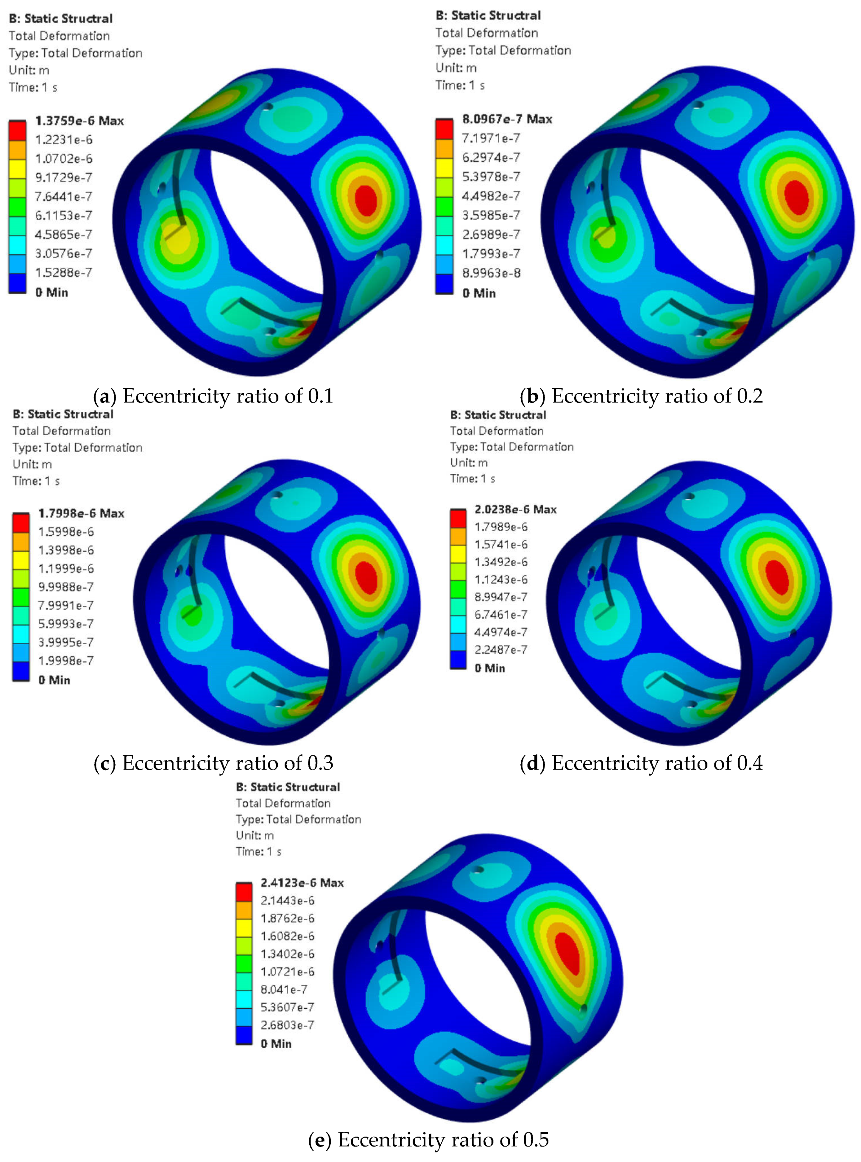
5.2. Effect of Eccentricity Ratio
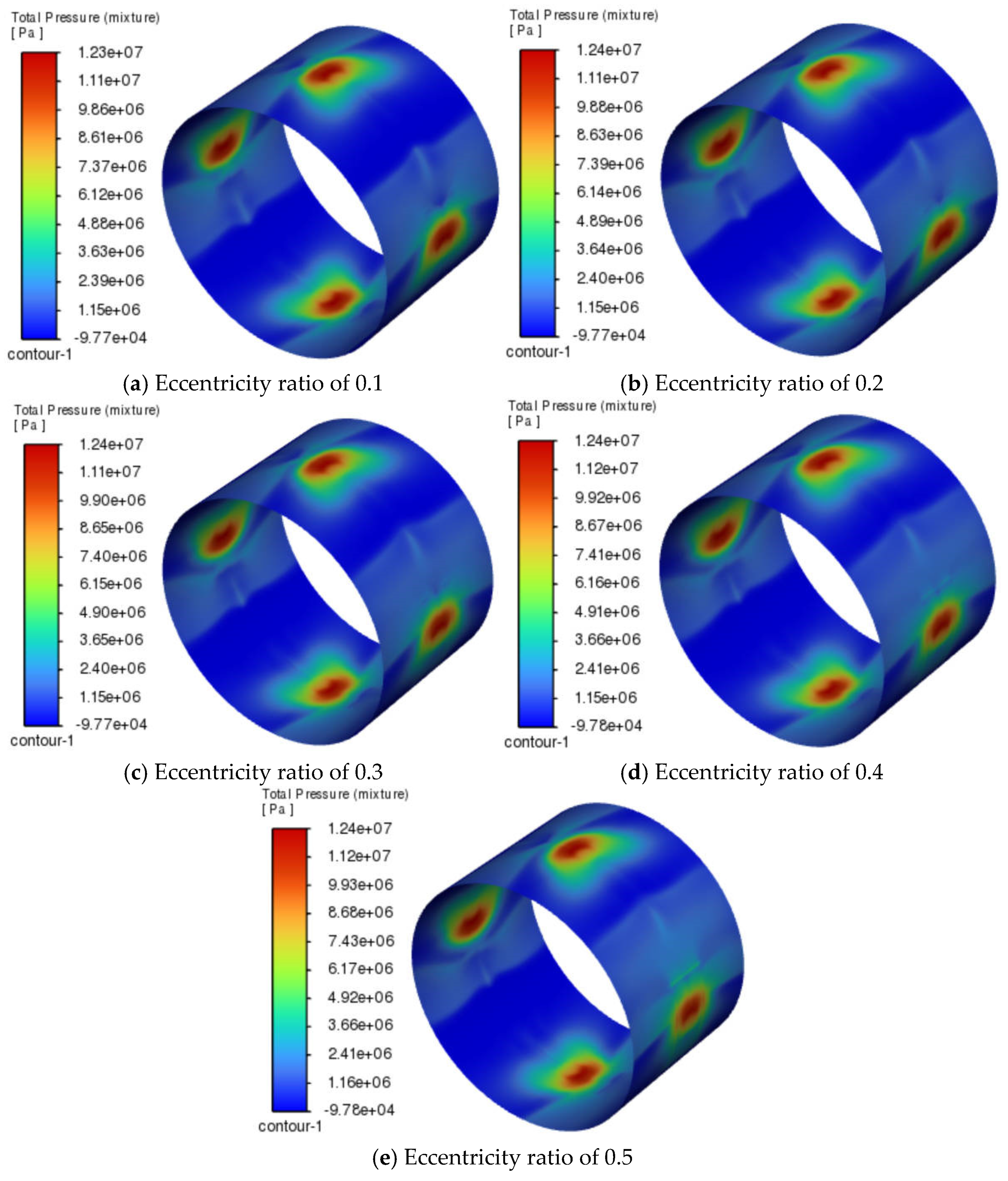
When the inlet diameter was 2 mm, the radial clearance was 0.3 mm, and the oil pocket dimensions (axial width in mm × pocket angle in rad) were 5 × 45. The effects of different eccentricities on the oil film pressure distribution and bearing deformation regions are shown in
Figure 10 and
Figure 11.
As shown in
Figure 10 and
Figure 11, when the eccentricity increased from 0.1 to 0.5 (
Figure 10a–e), the distribution of the negative pressure region remained largely unchanged. It still corresponded to the locations of the inlet ports but did not completely overlap with them, for reasons explained earlier and thus not repeated here. As the eccentricity increased, the main deformation area of the bearing gradually shifted to the right side of the inlet (
Figure 11a–e). The minimum deformation occurred at an eccentricity of 0.2 (
Figure 11b), and then gradually increased as the eccentricity rises.
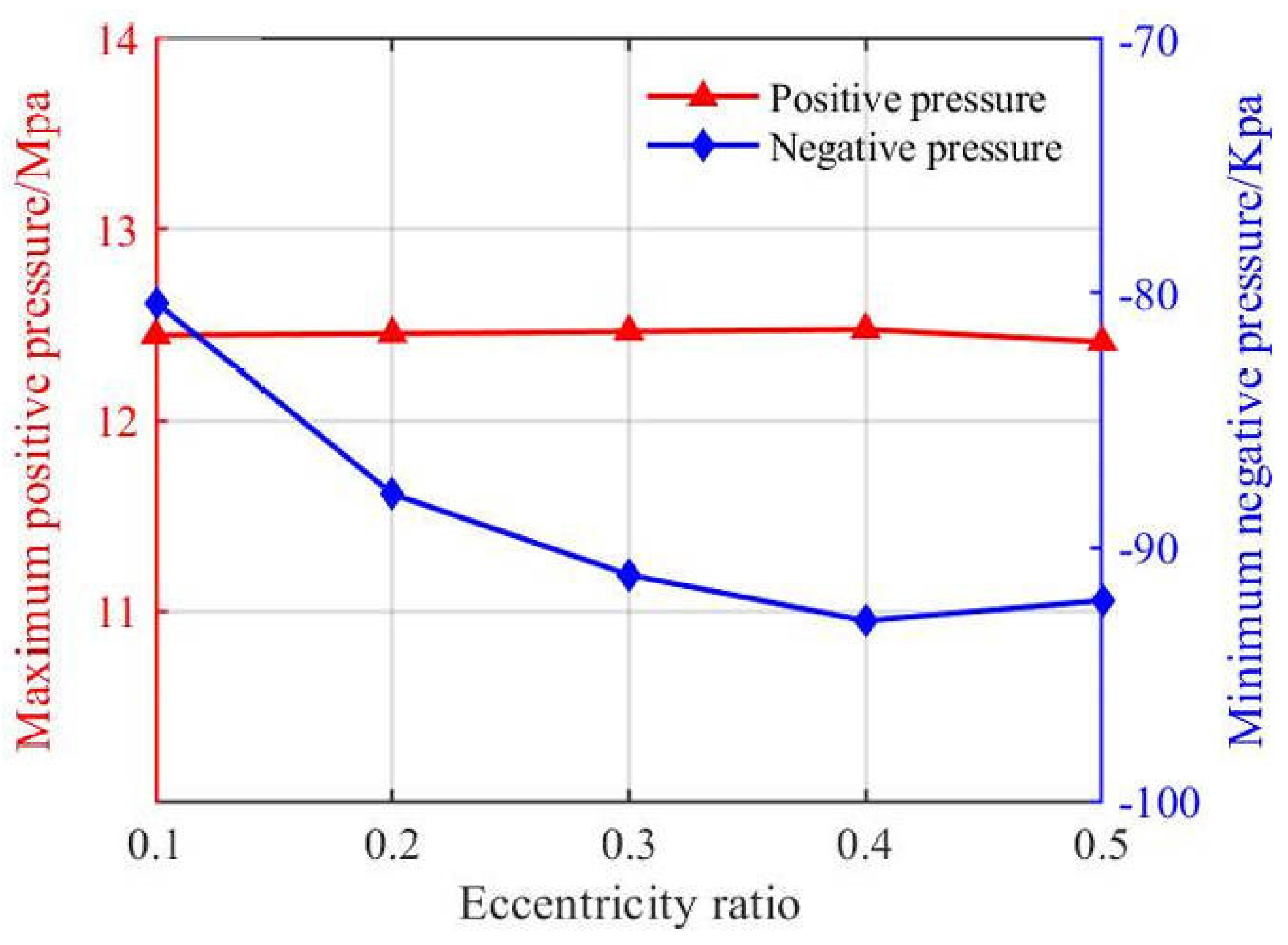
The variation curves of peak oil film pressure, load capacity, and friction coefficient as functions of eccentricity (from 0.1 to 0.5) are shown in
Figure 12 and
Figure 13.
As shown in
Figure 12 and
Figure 13, with increasing eccentricity, the maximum oil film pressure remained almost unchanged, while the minimum pressure gradually decreased and stabilized, with a value of −92.9 Kpa when the eccentricity reached 0.4–0.5. The increase in eccentricity intensified the impact of cavitation effects. As the eccentricity increased, both the load capacity and the friction coefficient showed an overall increasing trend. At an eccentricity of 0.3, the load capacity suddenly dropped, from 81.7 N to 52.8 N, and the friction coefficient began to stabilize, with a value of 1.78. The bearing deformation increased gradually as the eccentricity increased. Comparison between
Figure 9 and
Figure 13 shows that the load capacity increased with the growth of variable values. The inlet diameter had a greater influence on load capacity, likely due to the increased lubricant inflow per unit time, ensuring sufficient internal lubrication. As eccentricity increased, the maximum oil film pressure remained nearly constant while the minimum pressure decreased (expanding the negative pressure region). At the same time, both the load capacity and friction coefficient overall increased, and bearing deformation gradually increased.
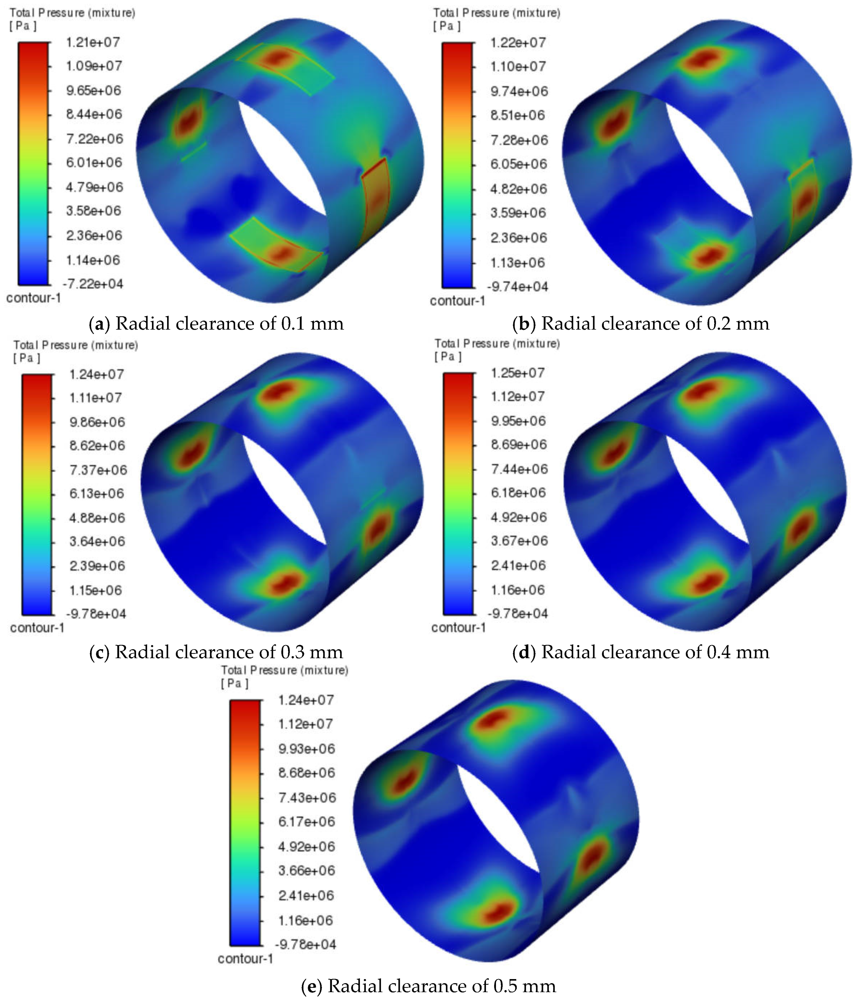
5.3. Effect of Radial Clearance
When the inlet diameter was 2 mm, the eccentricity was 0.5, and the oil pocket dimensions (axial width in mm × pocket angle in rad) were 5 × 45. The effects of different radial clearance on the oil film pressure distribution and bearing deformation regions are shown in
Figure 14 and
Figure 15.
As shown in
Figure 14 and
Figure 15, when the radial clearance was 0.1 mm (
Figure 14a), the oil pocket region was dominated by positive pressure, and the negative pressure region was not significant. The maximum positive pressure appeared inside the oil chamber. This occurred because the oil film was too thin, preventing supercritical CO
2 from fully entering the film, which led to a more pronounced positive pressure distribution. As the radial clearance increased, the negative pressure region became more pronounced, and its area expanded, as shown
Figure 14a–e. The bearing deformation decreased with increasing radial clearance, and the region of maximum deformation gradually shifted from the inlet to the side near the inlet, as shown
Figure 15a–e.
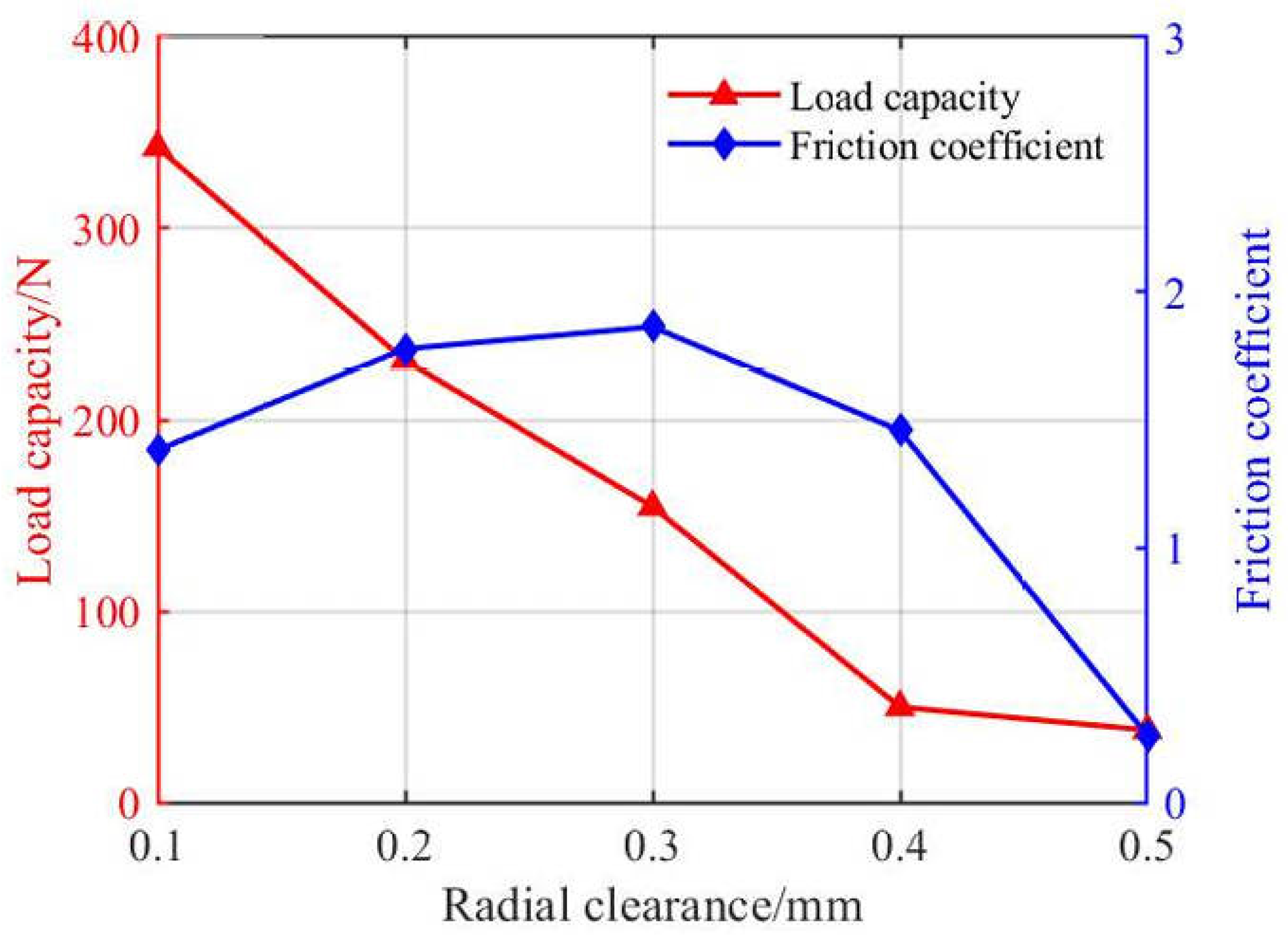
The variation curves of peak oil film pressure, load capacity, and friction coefficient as functions of radial clearance (from 0.1 mm to 0.5 mm) are shown in
Figure 16 and
Figure 17.
As shown in
Figure 16 and
Figure 17, with increasing radial clearance, both the maximum positive pressure and minimum negative pressure dropped significantly in the range of 0.1–0.2 mm. After that, the maximum positive pressure tended to stabilize near 12.4 Mpa, while the minimum negative pressure first increased and then decreased, reaching an extreme value of −89.2 Kpa. The load-carrying capacity was inversely proportional to the radial clearance and decreased accordingly. Due to parameter range limitations, this study did not identify the optimal bearing clearance for maximizing load capacity. A smaller radial clearance is hypothesized to enhance the load-carrying performance of supercritical CO
2-lubricated bearings. The friction coefficient showed a trend of slow increase followed by a sharp decrease, reaching an extreme value of 1.86. Comparison between
Figure 9 and
Figure 17 reveals that the friction coefficient first increased and then decreased with the growth of variable values. This trend may be related to changes in the negative pressure zone, where cavitation effects were mitigated.
Increasing the radial clearance significantly reduced the peak oil film pressure and expanded the negative pressure region, resulting in a markedly lower load capacity and decreased bearing deformation. Therefore, a smaller clearance helped improve load-carrying performance.
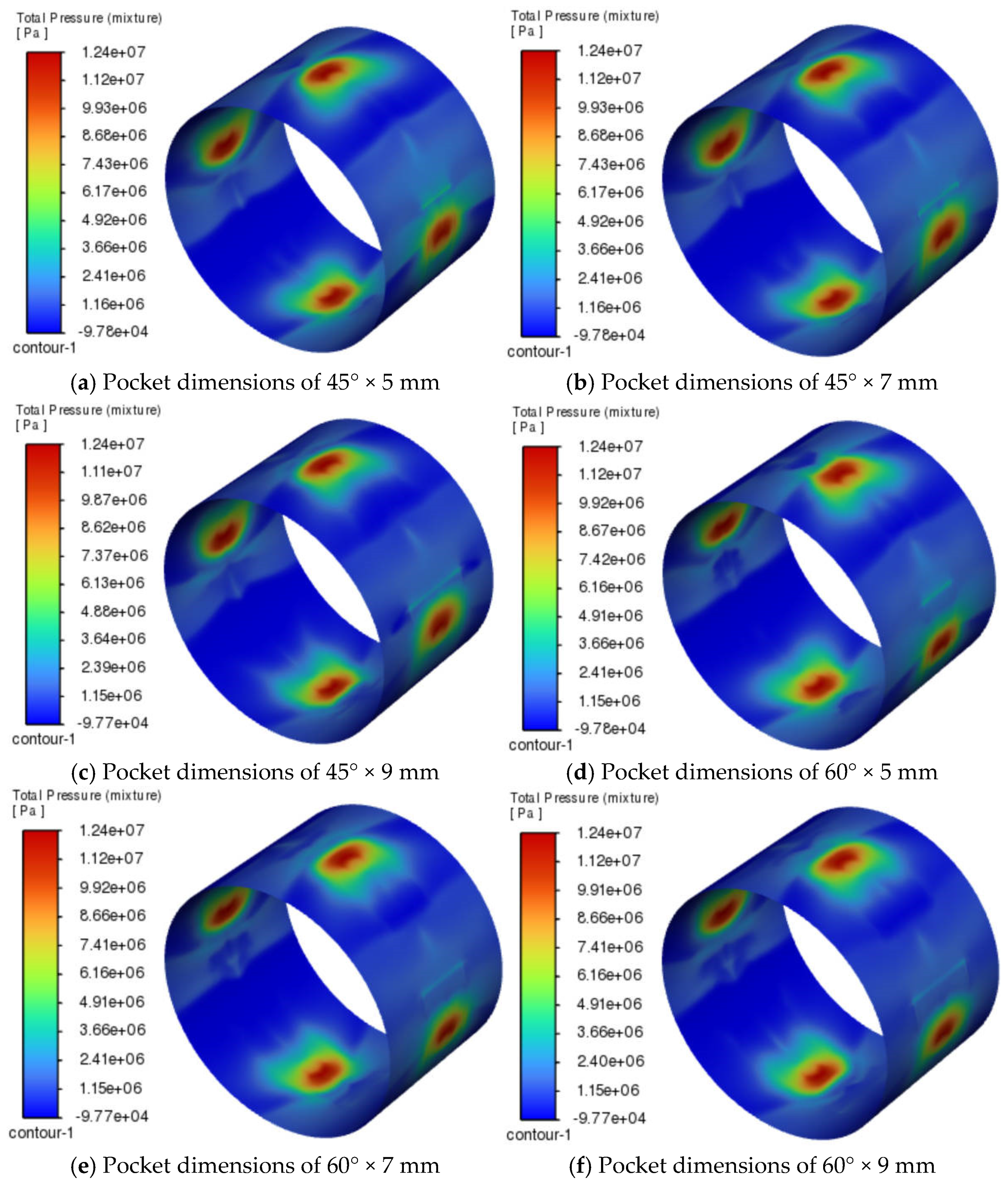
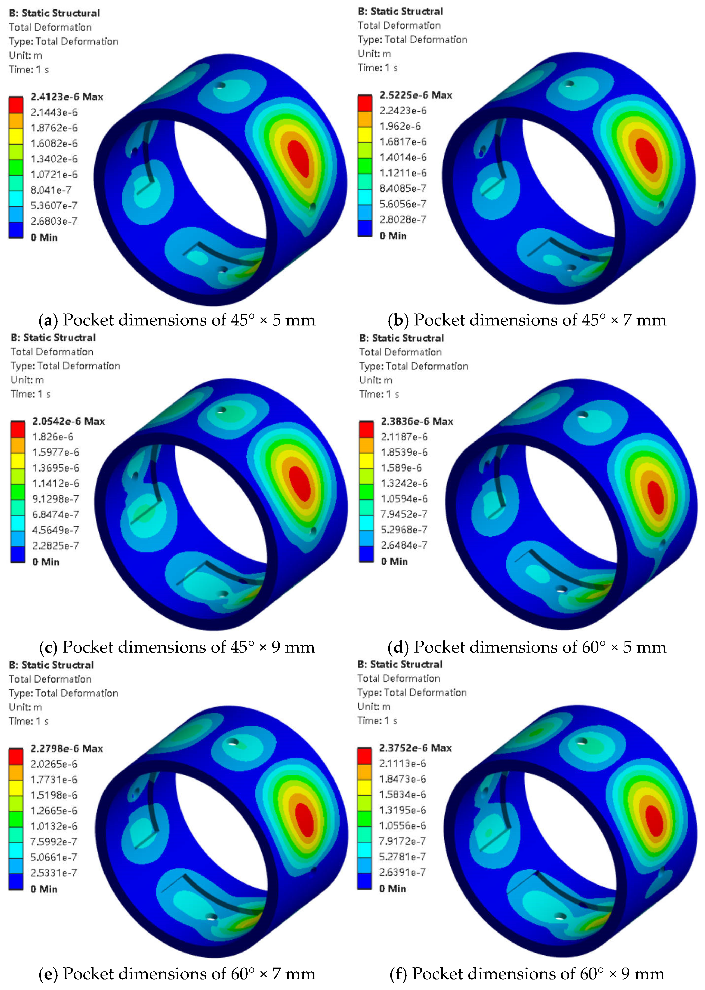
5.4. Effect of Oil Pocket Dimensions
When the inlet diameter was 2 mm, the eccentricity was 0.5, and the radial clearance was 0.3 mm. The effects of different oil pocket dimensions on the oil film pressure distribution and bearing deformation regions are shown in
Figure 18 and
Figure 19.
As shown in
Figure 18 and
Figure 19, when the oil groove wrap angle increased from 45° to 60° (
Figure 18a–c and
Figure 19d–f), the negative pressure region of the oil film showed a slight expansion, and the bearing deformation tended to increase, especially at larger axial widths. When the axial width increased (
Figure 18a–f), the negative pressure region changed little, while the bearing deformation tended to decrease (
Figure 19a–f). The variation trends in the oil film pressure peak, load capacity, and friction coefficient with changes in oil chamber dimensions are shown in
Figure 20 and
Figure 21.
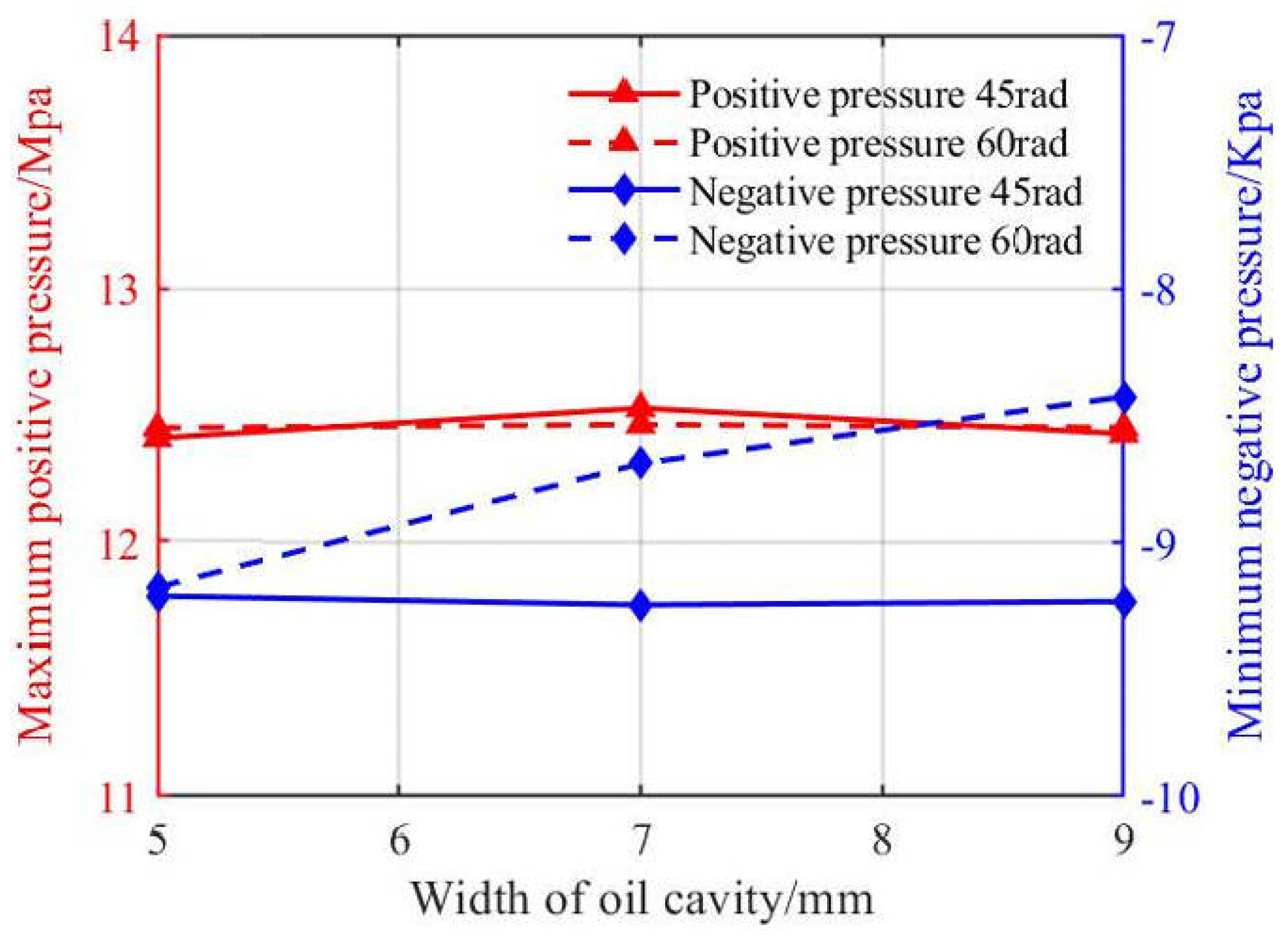
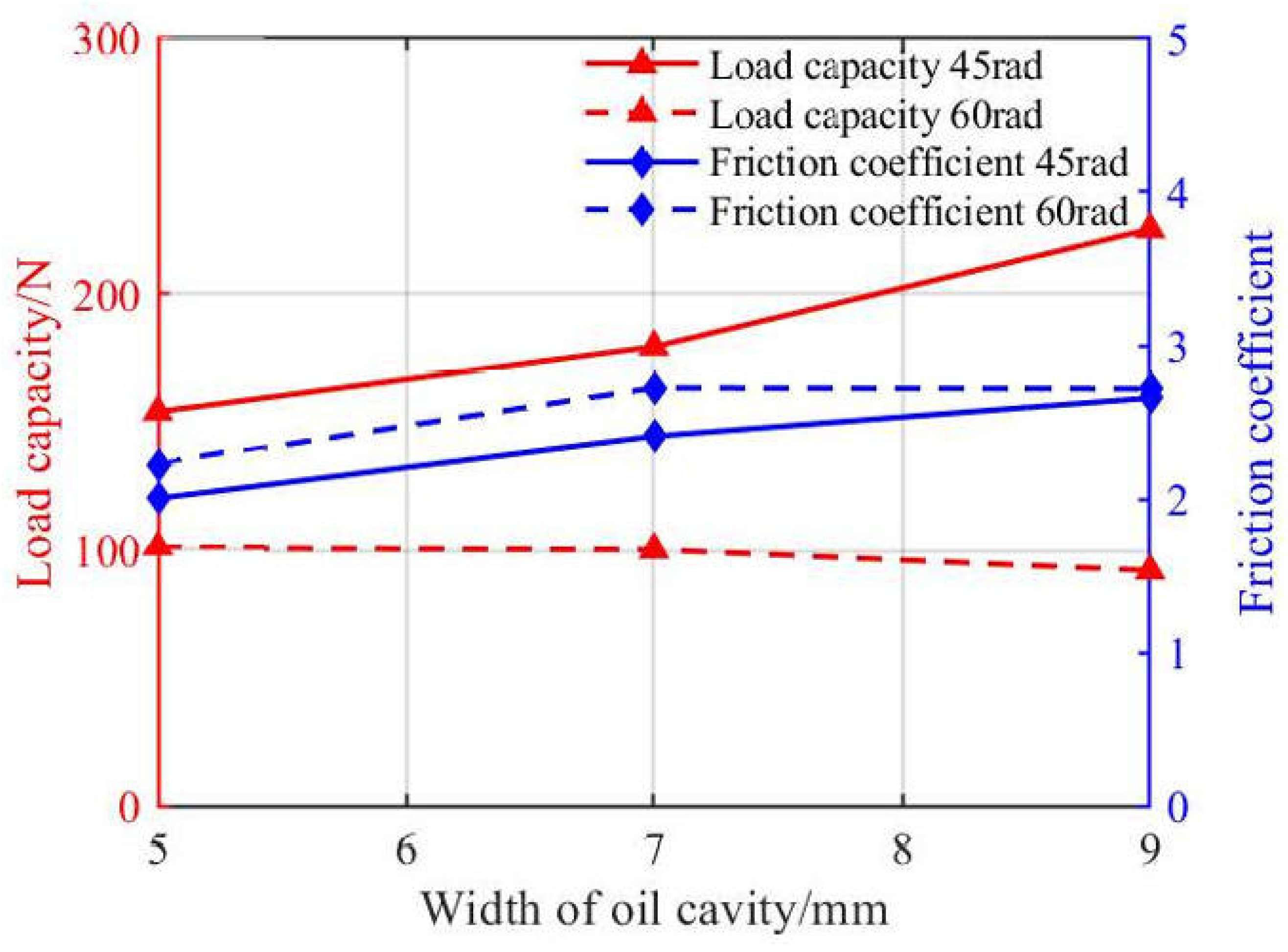
As shown in
Figure 20 and
Figure 21, as the axial width of the oil chamber increased, the maximum positive pressure showed little variation, with a value of 12.4 Mpa for both 45° and 60° wrap angles. At a 60° wrap angle, the minimum negative pressure increased proportionally with axial width. At a 45° wrap angle, the minimum negative pressure showed no clear trend, with a value of 92.4 Kpa. With increasing axial width, both load capacity and friction coefficient remained nearly unchanged near 100 N and 2.74. When the wrap angle increased from 45° to 60°, the load capacity decreased slightly overall.
Increasing the groove wrap angle slightly expanded the negative pressure region and slightly reduced the load capacity, while increasing the axial width has almost no effect on pressure peaks, load capacity, or friction. Overall, a reduced wrap angle modestly enhanced the bearing’s load capacity.
5.5. Practical Considerations for S-CO2-Lubricated Bearings
This study revealed the parameter optimization trends of S-CO2-lubricated bearings under ultra-high-speed conditions. However, its engineering application still faces the following key issues:
(1) Thermal Management Challenge: The viscosity of supercritical CO
2; is highly temperature-sensitive (
Figure 1). Under high-speed and heavy-load conditions, local temperature rise in the bearing may cause a sharp drop in viscosity, weakening the oil film’s load-carrying capacity. Although thermal effects were not considered in this study, the negative pressure zones observed in simulations (
Figure 6,
Figure 10, and
Figure 14) were prone to cavitation, which increased the temperature rise. It is recommended to incorporate a thermo-fluid-structure coupling model in future studies. This will help assess the impact of different cooling strategies, such as forced convection cooling, on oil film stability.
(2) Structural Adaptability Design: The research showed that a small oil cavity angle (45°) can improve load capacity. However, it is important to balance manufacturing precision (micrometer-level gap control) with dynamic response. Increasing the inlet diameter improves load capacity but also increases friction and the risk of housing deformation (
Figure 7). For practical applications, a gradient aperture design is suggested. This involves a large inlet diameter for better lubrication supply and a smaller outlet diameter to maintain pressure, balancing supply efficiency and structural rigidity.
(3) Environmental Adaptability Extension: The current model assumes a constant temperature of 320 K. However, practical applications, such as spacecraft turbines, face cold-start issues at low temperatures. Further research is needed on the impact of subcritical/supercritical phase transitions on oil film formation. Special attention should be given to the lubricating properties in the density jump region near the critical point (
Figure 1b).


