Modeling of the Dynamics of Conical Separate Plates in a Wet Multi-Disc Clutch


Abstract
1. Introduction
2. Numerical Model
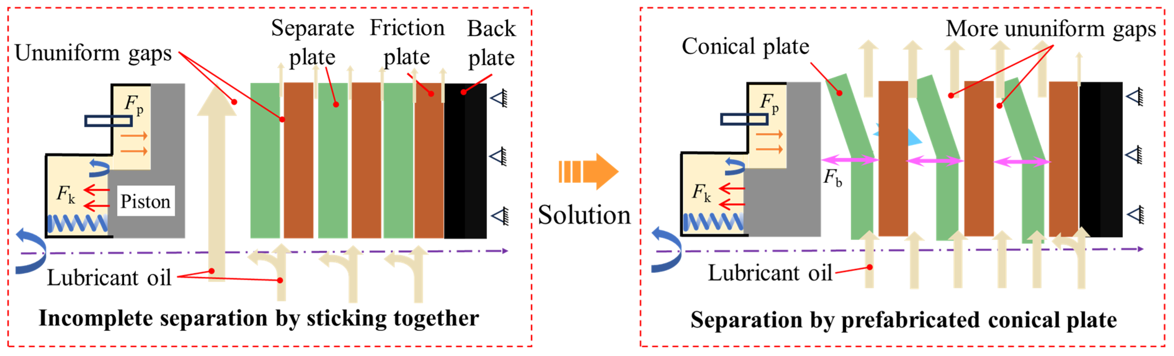
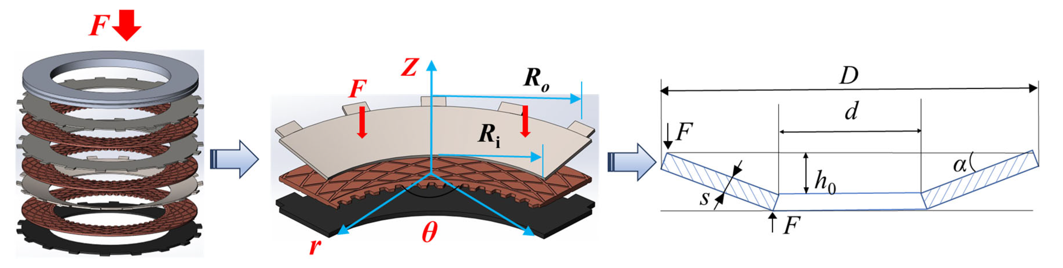
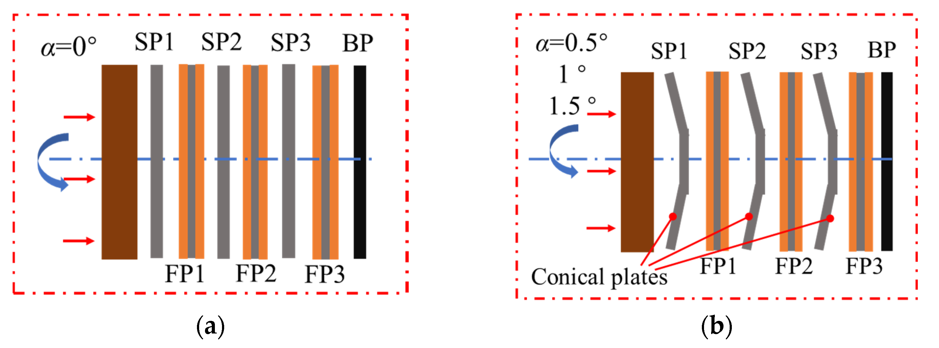
2.1. Conical Separate Plate Design
2.2. Dynamic Model
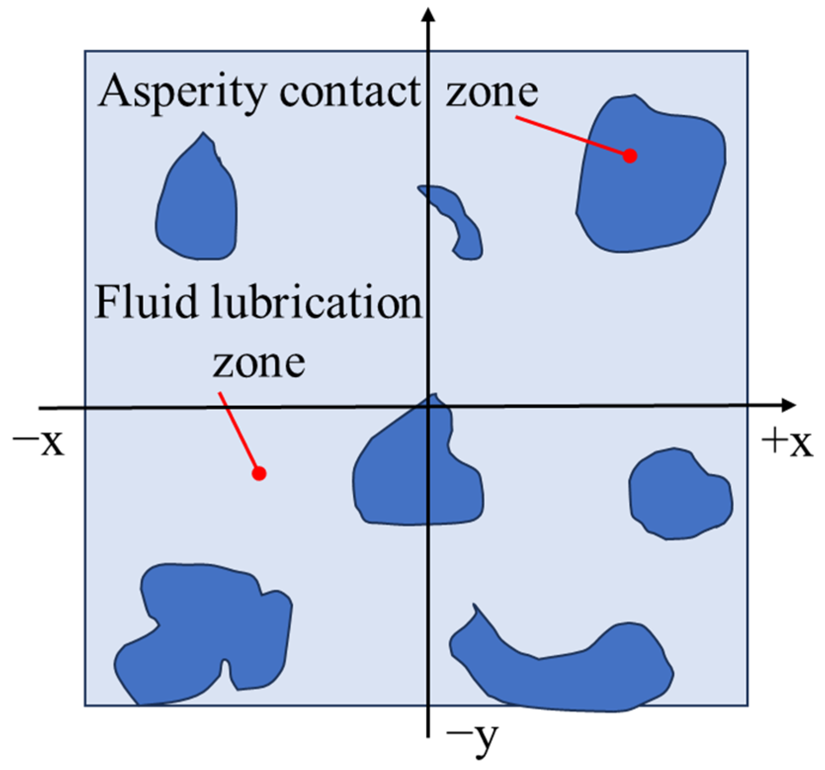
2.3. Contact and Lubrication Model
2.4. Torque Model
3. Experiments
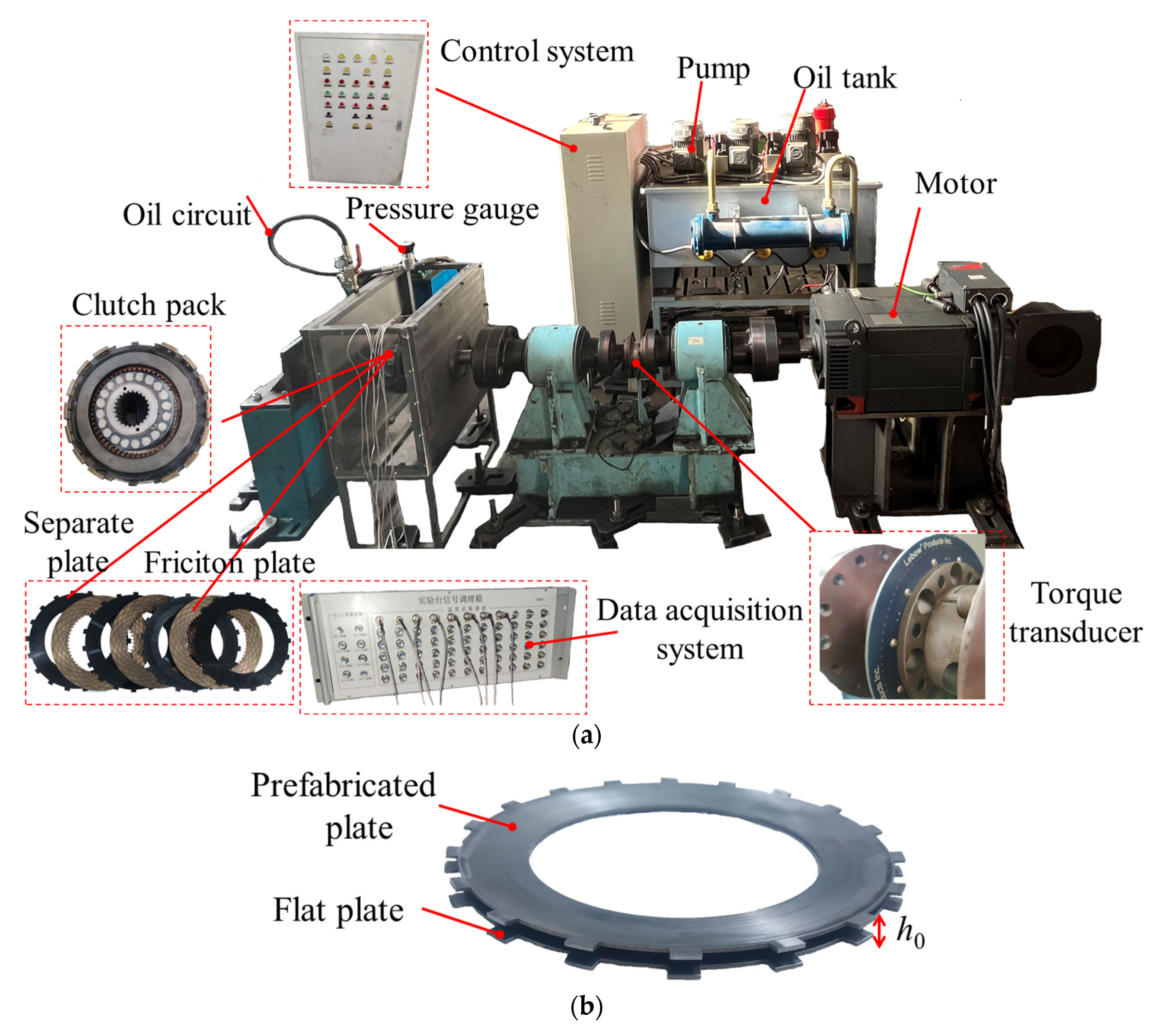
3.1. Apparatus
3.2. Methods
4. Results and Discussion
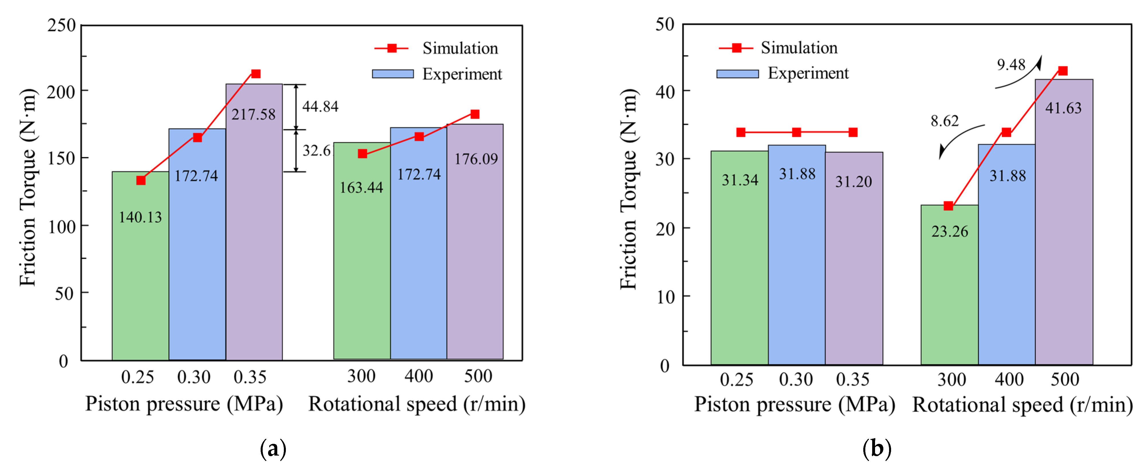
4.1. Model Verification
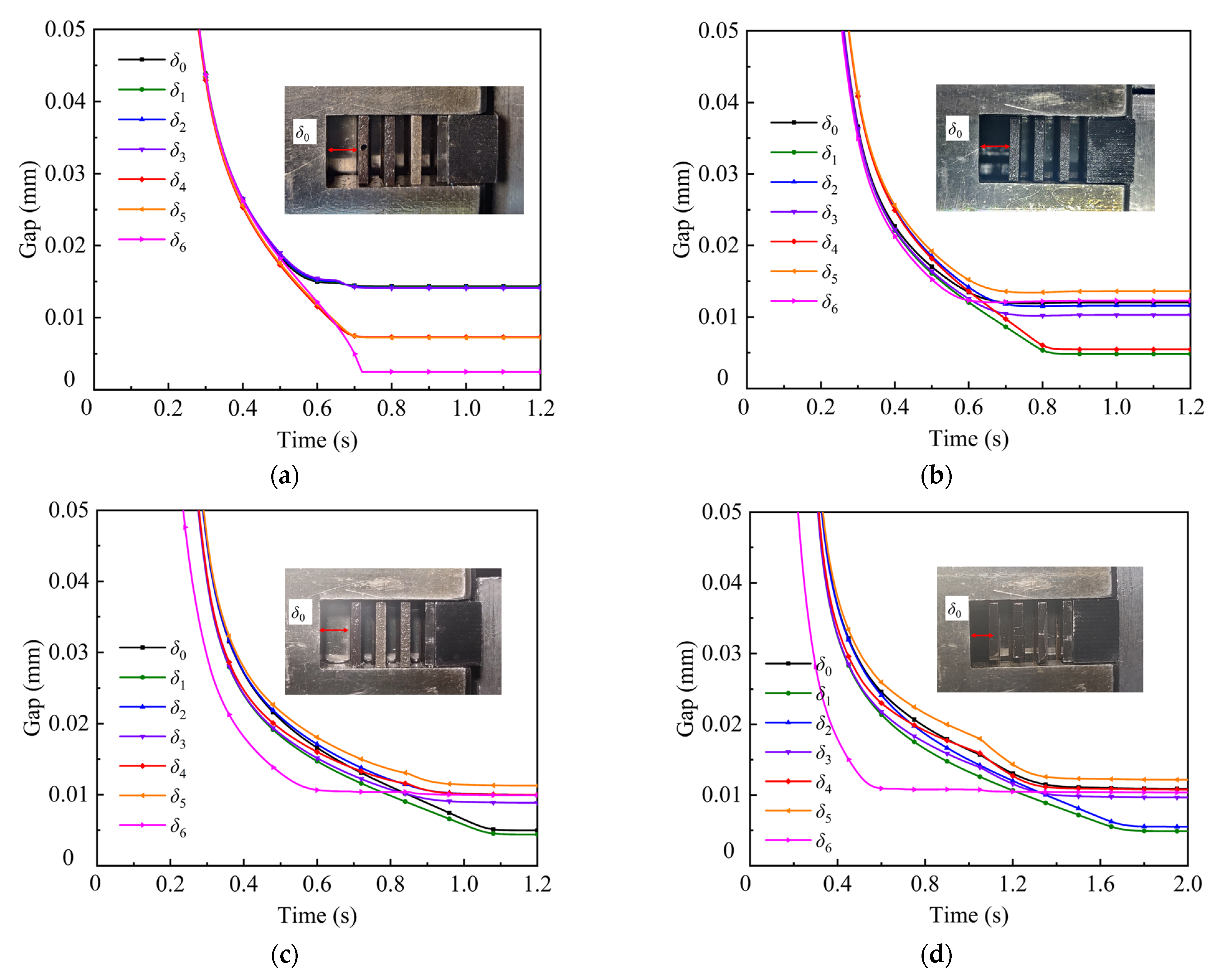
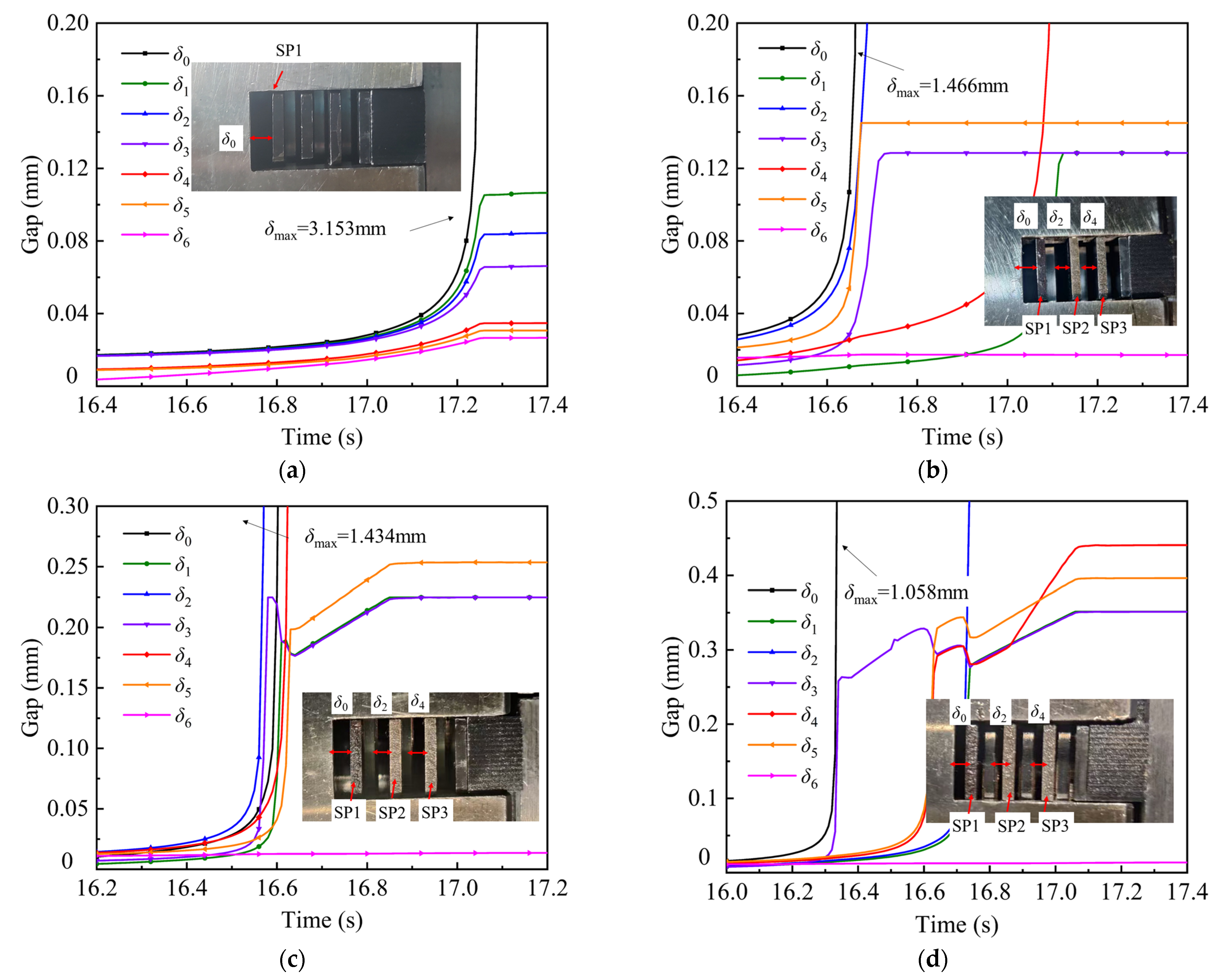
4.2. Gap Characteristics
4.3. Torque Characteristics
5. Conclusions
- (1)
- The conical plate can provide elastic restoring force during the separation process to assist separation, reducing the separation time by 18.78%. The uniformity of the gaps is increased by 25.31%, resulting in a change in the lubrication status from the mixture lubrication to the hydrodynamic lubrication.
- (2)
- The established numerical model can effectively describe the clutch engagement and separation characteristics, and its feasibility is verified by experiments. As evidenced by the simulations and experiments, the best layout is the 1° conical plates.
- (3)
- By avoiding the sticking of the friction components, 37.73% of the drag torque is reduced and the transmitted torque is reduced by 10.31%. Since the separation status occupies most of the operating time, the trade-off is acceptable. In addition, under higher-piston-pressure conditions, the influence on the transmitted torque, but not the drag torque, can be reduced.
Author Contributions
Funding
Data Availability Statement
Conflicts of Interest
References
- Šabík, V.; Futáš, P.; Pribulová, A. Failure analysis of a clutch wheel for wind turbines with the use of casting process simulation. Eng. Fail. Anal. 2022, 135, 106159. [Google Scholar] [CrossRef]
- Zhang, Z.; Mu, Z.; Yu, X. Mechanistic Study of Groove Parameters on the Thermoelastic Instability of Wet Clutch. Lubricants 2025, 13, 150. [Google Scholar] [CrossRef]
- Wu, J.; Wang, L.; Li, L.; Shu, Y.; Yang, L.; Lei, T.J.M. Sliding State Analysis of Fractal Rough Interface Based on the Finite Element Method. Materials 2021, 14, 2121. [Google Scholar] [CrossRef] [PubMed]
- Wu, Y.; Liu, Y.; Chen, H.; Chen, Y.; Xie, D. An investigation into the failure mechanism of severe abrasion of high-speed train brake discs on snowy days. Eng. Fail. Anal. 2019, 101, 121–134. [Google Scholar] [CrossRef]
- Zhang, Z.; Zou, L.; Liu, H.; Feng, J.; Chen, Z. Response Characteristics of Dynamic Torque for Wet Clutch Engagement: A Numerical and Experimental Study. Shock Vib. 2021, 2021, 5522998. [Google Scholar] [CrossRef]
- Pointner-Gabriel, L.; Schermer, E.; Schneider, T.; Stahl, K. Experimental analysis of oil flow and drag torque generation in disengaged wet clutches. Sci. Rep. 2023, 13, 17193. [Google Scholar] [CrossRef]
- Falade, A.; Brenner, H. First-order wall curvature effects upon the Stokes resistance of a spherical particle moving in close proximity to a solid wall. J. Fluid Mech. 1988, 193, 533–568. [Google Scholar] [CrossRef]
- Yuan, Y.; Liu, E.A.; Hill, J.; Zou, Q. An Improved Hydrodynamic Model for Open Wet Transmission Clutches. J. Fluids Eng. 2006, 129, 333–337. [Google Scholar] [CrossRef]
- Jakubov, T.S.; Mainwaring, D.E. The surface tension of a solid at the solid–vacuum interface, an evaluation from adsorption and wall potential calculations. J. Colloid Interface Sci. 2007, 307, 477–480. [Google Scholar] [CrossRef]
- Pointner-Gabriel, L.; Flamm, S.; Menzel, M.; Voelkel, K.; Stahl, K. Experimental investigation of drag loss and plate separation behavior of wet clutches under external forces. Results Eng. 2024, 24, 102918. [Google Scholar] [CrossRef]
- Mahmud, S.F.; Pahlovy, S.A.; Kubota, M.; Ogawa, M.; Takakura, N. Multi-Phase Simulation for Studying the Effect of Different Groove Profiles on the Drag Torque Characteristics of Transmission Wet Clutch; 2016-01-1144; SAE International: Warrendale, PA, USA, 2016. [Google Scholar]
- Fish, R.L. Using the SAE #2 Machine to Evaluate Wet Clutch Drag Losses. SAE Trans. 1991, 100, 1041–1054. [Google Scholar]
- Pointner-Gabriel, L.; Menzel, M.; Voelkel, K.; Schneider, T.; Stahl, K. Experimental investigation of drag loss behavior of dip-lubricated wet clutches for building a data-driven prediction model. Sci. Rep. 2024, 14, 9241. [Google Scholar] [CrossRef] [PubMed]
- Leister, R.; Najafi, A.F.; Gatti, D.; Kriegseis, J.; Frohnapfel, B. Non-dimensional characteristics of open wet clutches for advanced drag torque and aeration predictions. Tribol. Int. 2020, 152, 106442. [Google Scholar] [CrossRef]
- Neupert, T.; Bartel, D. Evaluation of Various Shear-Thinning Models for Squalane Using Traction Measurements, TEHD and NEMD Simulations. Lubricants 2023, 11, 178. [Google Scholar] [CrossRef]
- Hilpert, C.R. Gyroscopically Induced Failure in Multiple Disc Clutches, Its Causes, Its Characteristics and Its Cures. SAE Trans. 1969, 78, 354–371. [Google Scholar]
- Hou, S.; Hu, J.; Peng, Z. Experimental Investigation on Unstable Vibration Characteristics of Plates and Drag Torque in Open Multiplate Wet Clutch at High Circumferential Speed. J. Fluids Eng. 2017, 139, 111103. [Google Scholar] [CrossRef]
- Yu, Y.; Peng, Y.; Lan, S.; Zhou, P. Finite Element Analysis for Wave Spring of Multi-Disc Wet Clutch Based on ANSYS. Appl. Mech. Mater. 2013, 419, 203–208. [Google Scholar] [CrossRef]
- Erfanian-Naziftoosi, H.R.; Shams, S.S.; Elhajjar, R. Composite wave springs: Theory and design. Mater. Des. 2016, 95, 48–53. [Google Scholar] [CrossRef]
- Li, S.-X.; Liao, H.-R.; Li, S.-C.; Chen, L.; Li, Q.-Z.; Cheng, T.-F.; Chen, K.-Y. Effect of structural parameters on the bearing characteristics of wave spring. J. Mach. Des. 2020, 37, 22–27. [Google Scholar] [CrossRef]
- Yan, Z.; Wu, B.; Gao, X.; Bai, X. Engagement/Disengagement Characteristics of Pull-Type Diaphragm Spring Clutch for Heavy-Duty Commercial Vehicles. Chin. J. Mech. Eng. 2024, 37, 124. [Google Scholar] [CrossRef]
- Wang, H.; Zhu, C.; Yang, X.; Niu, Y.; Bao, H.; Zhu, R. Study on the engagement characteristics of wet multi-plate friction clutch based on separating spring. Forsch. Im Ingenieurwesen 2024, 88, 3. [Google Scholar] [CrossRef]
- Wu, J.; Cui, J.; Shu, W.; Wang, L.; Li, H. Coupling mechanism and data-driven approaches for high power wet clutch torque modeling and analysis. Tribol. Int. 2024, 191, 109166. [Google Scholar] [CrossRef]
- Zhao, Q.; Ma, B.; Yu, L.; Zhang, Y.; Dong, Y.; Zhou, R. Numerical and experimental studies on the thermodynamic characteristics of post-buckling separate plate in the clutch. Tribol. Int. 2024, 195, 109607. [Google Scholar] [CrossRef]
- Matsuoka, T. Study on Effect of Oiliness Agents in the Presence of Detergents on Friction Characteristics of Paper-Based Friction Materials Under Low Sliding Velocity. Jpn. J. Tribol. 2002, 47, 488–497. [Google Scholar]
- Greenwood, J.; Williamson, J. Contact of Nominally Flat Surfaces. Proc. R. Soc. Lond. 1966, 295, 300–319. [Google Scholar] [CrossRef]
- Jung, W.; Hyeon, J.; Doh, N. Robust Cuboid Modeling from Noisy and Incomplete 3D Point Clouds Using Gaussian Mixture Model. Remote Sens. 2022, 14, 5035. [Google Scholar] [CrossRef]
- Bao, H.; Xu, T.; Jin, G.; Huang, W. Analysis of Dynamic Engaged Characteristics of Wet Clutch in Variable Speed Transmission of a Helicopter. Processes 2020, 8, 1474. [Google Scholar] [CrossRef]
- Zheng, L.; Ma, B.; Chen, M.; Yu, L.; Xue, J. Numerical studies on the dynamic characteristics of a wet multi-disc clutch during the disengaging process. J. Mech. Sci. Technol. 2022, 36, 3277–3289. [Google Scholar] [CrossRef]
- Shutin, D.; Kazakov, Y. Theoretical and Numerical Investigation of Reduction of Viscous Friction in Circular and Non-Circular Journal Bearings Using Active Lubrication. Lubricants 2023, 11, 218. [Google Scholar] [CrossRef]
- Yu, L.; Ma, B.; Chen, M.; Li, H.; Liu, J.; Li, M. Investigation on the failure mechanism and safety mechanical-thermal boundary of a multi-disc clutch. Eng. Fail. Anal. 2019, 103, 319–334. [Google Scholar] [CrossRef]


| Case | Cone Angle (°) | Piston Pressure (MPa) | Rotational Speed (r/min) |
|---|---|---|---|
| C-0 | 0 | 0.25, 0.3, 0.35 | 300, 400, 500 |
| C-1 | 0.5 | ||
| C-2 | 1 | ||
| C-3 | 1.5 |
| 0° | 0.5° | 1° | 1.5° | |
|---|---|---|---|---|
| te (s) | 0.79 | 0.90 | 1.18 | 1.87 |
| ts (s) | 2.29 | 2.03 | 1.86 | 2.09 |
| δ0 (mm) | 3.153 | 1.466 | 1.434 | 1.058 |
| δu | 0.9208 | 0.7315 | 0.6877 | 0.6528 |
Disclaimer/Publisher’s Note: The statements, opinions and data contained in all publications are solely those of the individual author(s) and contributor(s) and not of MDPI and/or the editor(s). MDPI and/or the editor(s) disclaim responsibility for any injury to people or property resulting from any ideas, methods, instructions or products referred to in the content. |
© 2025 by the authors. Licensee MDPI, Basel, Switzerland. This article is an open access article distributed under the terms and conditions of the Creative Commons Attribution (CC BY) license (https://creativecommons.org/licenses/by/4.0/).
Share and Cite
Zhao, Q.; Ma, B.; Xiong, C.; Yu, L.; Fu, B.; Yan, S. Modeling of the Dynamics of Conical Separate Plates in a Wet Multi-Disc Clutch. Lubricants 2025, 13, 262. https://doi.org/10.3390/lubricants13060262
Zhao Q, Ma B, Xiong C, Yu L, Fu B, Yan S. Modeling of the Dynamics of Conical Separate Plates in a Wet Multi-Disc Clutch. Lubricants. 2025; 13(6):262. https://doi.org/10.3390/lubricants13060262
Chicago/Turabian StyleZhao, Qin, Biao Ma, Cenbo Xiong, Liang Yu, Bing Fu, and Shufa Yan. 2025. "Modeling of the Dynamics of Conical Separate Plates in a Wet Multi-Disc Clutch" Lubricants 13, no. 6: 262. https://doi.org/10.3390/lubricants13060262
APA StyleZhao, Q., Ma, B., Xiong, C., Yu, L., Fu, B., & Yan, S. (2025). Modeling of the Dynamics of Conical Separate Plates in a Wet Multi-Disc Clutch. Lubricants, 13(6), 262. https://doi.org/10.3390/lubricants13060262