Abstract
The aim of the present study was to develop a concept for the inverse analysis of wear mechanisms in cast steel wheels of a pig iron wagon after long-term operation. Samples were taken from the flange and the tread edge area of fourteen wheels. The impact of wheel parameters and repair methods on their wear was assessed. An analysis was carried out to determine whether welds were made as part of casting correction or as repair welds. Changes in the microstructure of the weld area, the heat-affected zone, and the parent material resulting from operation were determined. The main wear mechanism in the area of the welds and the parent material is the plastic flow of the material resulting from high unit pressures. The hardness of the material is found to be contingent upon its chemical composition, the microstructural components, and the degree of plastic deformation resulting from wear (it has been established that increasing alloying results in increased hardness; a comparable effect is observed in the formation of non-equilibrium structures (bainite)). The increase in hardness is attributed to strain hardening, a consequence of exploitation. Research and analytical methods have been developed to differentiate the results of repair processes for wear effects in a highly loaded friction node with non-stationary lubrication conditions from repair processes applied to castings of large structural components.
1. Introduction
The smelting of raw iron from ore is typically accomplished through the utilization of the blast furnace process [1,2,3]. The resultant pig iron is then transported via rail to the bottling stations, mostly using the ladles for this purpose. The smelted ore is transported by rail using specialized wagons known as pig iron wagons [4].
The design of special railway platforms employed within the metallurgical industry is mainly based on a designed wheel set, comprising an axle and two wheels, the function of which is to roll on the rails. The main tasks of the wheel set include [1,5]:
- allowing the vehicle to move on the track;
- transferring the weight of the loaded vehicle;
- transferring the driving and braking forces, as well as dynamic loads caused by track unevenness.
Monolithic wheels may have indirect or direct contact with the rail. In railway transport, two types of wheels can be distinguished (Figure 1) [1,5]:
- monoblock wheels;
- tired wheels, which include a bare wheel and the tire around the outside.
 Figure 1. Comparison of bare wheel (a) and tyred wheel (b) [6].Figure 1. Comparison of bare wheel (a) and tyred wheel (b) [6].
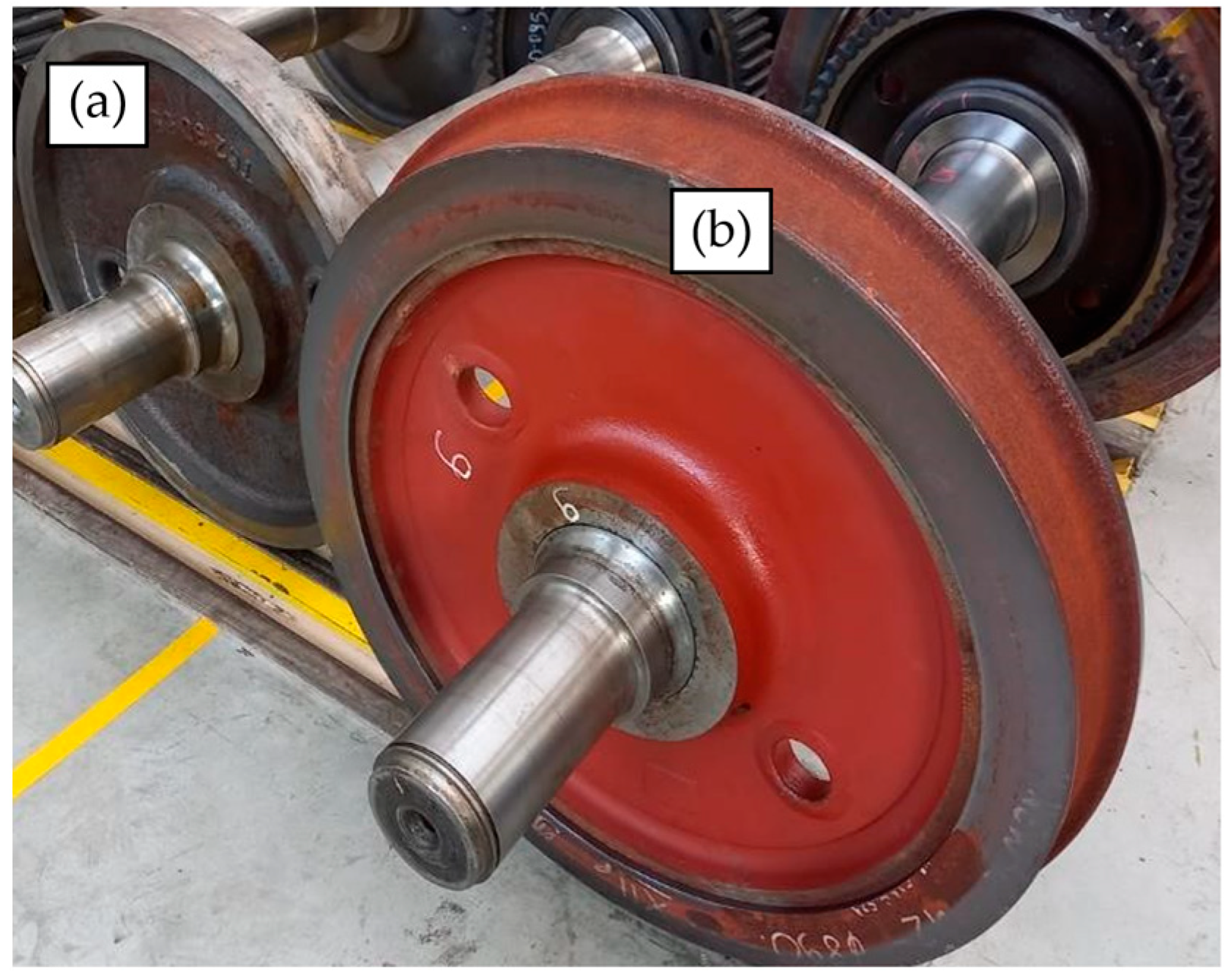
The utilization of a monoblock wheel, owing to its monolithic nature, is significantly economical than a tyred wheel. This is primarily attributed to its enhanced durability and reduced manufacturing expenses [1,6].
1.1. Monoblock Wheel Construction
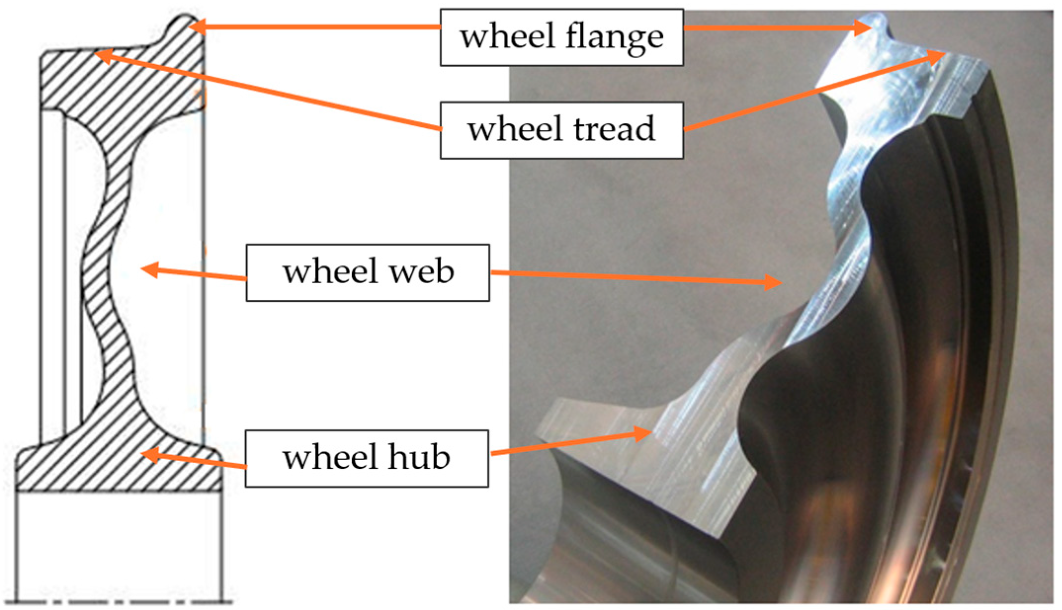
The monoblock wheels’ monolithic nature simplifies their construction and production. The manufacturing process involves machining a monoblock to obtain the designed shape [1,5,6]. The wheel’s design comprises a flange and a tread that are in direct contact with rails, and a web (Figure 2).
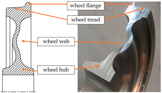
Figure 2.
Cross-section of a monoblock wheel [6].
Wheel sets used in the railway industry represent critical components of rail vehicles, significantly influencing vehicle mobility and transport safety during movement. This is attributable to the impact of static and dynamic forces on the axles associated with the wheels. The utilization of these wheel sets under continuous conditions, whilst the vehicle is in motion and bearing substantial loads, including those stemming from track irregularities, results in the tribological deterioration of the surface layers of the working elements [7,8,9,10]. The decision to repair road wheels rather than replace them has been prompted by the emergence of damage in the form of large gaps and cracks. Furthermore, the continuous increase in the cost of the materials required for such repairs has led to a shift in focus towards the regeneration of existing components. This approach is regarded as a significant ecological measure, as it facilitates the reuse of parts, thereby reducing the environmental impact associated with the production of new materials [1]. One method of enhancing the durability of elements that are in direct contact with railway rails is the process of welding [11,12,13]. In order to ensure the effective and responsible execution of welding operations on critical elements, a set of standards has been developed. These standards, to which service companies are expected to comply, form a framework for the responsible practice of welding [1,5,14,15].
1.2. Operation of a Railway Wheel
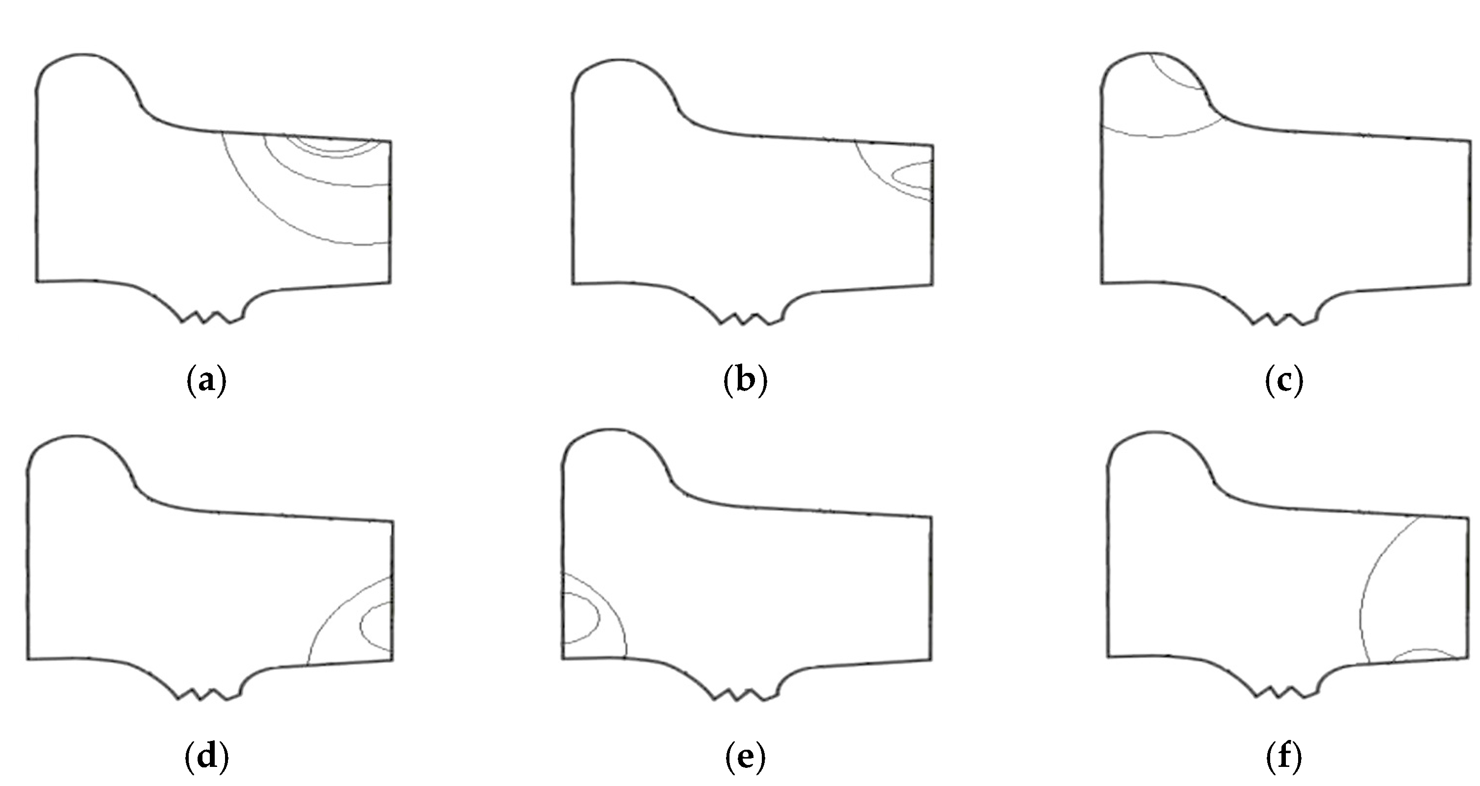
Railway wheels are subject to a multitude of operating factors, including static loads, dynamic loads, and impact loads. These phenomena are the result of external forces, internal stresses, corrosion, thermal and mechanical phenomena, or friction. Due to the wide range of tasks assigned to wheel sets, damage occurs in the form of discontinuities or wear marks [1,16,17]. The most common damages include fatigue cracks that appear in various places on the flange and tread. The following areas are of particular significance in terms of crack formation (Figure 3):
- (a)
- rolling surface (6–17%);
- (b)
- outer edge (40–60%);
- (c)
- flange (2–10%);
- (d)
- marks on the outer side surface (3–10%);
- (e)
- marks on the inner side surface (2–5%);
- (f)
- defective attachment surface (10–35%).
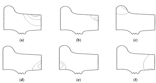
Figure 3.
Location of fatigue crack formation in the wheel.
Figure 3.
Location of fatigue crack formation in the wheel.
The deterioration of the monoblock wheel is contingent on the dimensions and category of the load during transportation, with the utilization of load levels that exceed the established limits resulting in a reduction in the operational longevity of the wheel set [18,19]. The prolonged use of monoblock wheels frequently results in surface destruction and the formation of cracks. The damage to the wheelset Maglio et al. conducted a study to examine the impact of railway wheel tread damage on rail wheel impact loads and the durability of wheelsets. They investigated the correlation between the magnitude of the impact load and various operational parameters and presented a methodology for predicting the effects of three-dimensional scanned wheel tread degradation on the durability of railway wheels, axles, and bearings [20].
1.3. Welding Repair Method of Cast Wheels
In order to avoid the replacement of the entire wheel, which would require a significant financial investment, the process of regeneration is performed in accordance with the [15]. This standard concerns the requirements and tests of steel castings for use in the railway industry [1,15]. The repair process may be carried out using welding or other methods agreed between the service ordering party and the contractor [15,19].
Welding is widely used in industrial processes that play a crucial role in prolonging the lifetime of the worn-out components or protecting machine parts from wear. Various welding techniques such as plasma transfer arc welding, gas metal arc welding, laser beam welding, and submerged arc welding are employed for overlay welding [11,19].
During the 1990s, the Paton Electric Welding Institute undertook extensive research on the welding and repair technology of railway wheels, which is still in use today [18,19]. The Welding Institute (TWI), as part of the AURORA project, researched the use of submerged arc welding technology for the repair of railway wheels. The primary objective of this research was to ensure stability and to minimize defects by welding [21]. Goo et al. restored the flange of the wheel, by overlay welding using the CO2 arc welding technique and evaluated the mechanical and wear characteristics of the restored railway wheel [18]. Coo and Lee conducted a study to repair a railway wheel by welding using the submerged arc welding technique and analyzed the changes in mechanical properties due to welding [22]. Byung-Ryeol et al. undertook a study of a welding repair method that minimizes the wheel cutting thickness and extends the service life. This was achieved by locally welding and cutting the wheel flange, which is a major wear area. It is anticipated that the implementation of the welding repair method, employing submerged arc welding to achieve a bainitic microstructure in the weld metal, will have the effect of extending the service life by more than 1.5 times [19].
The process of wheel regeneration by welding is accomplished through the utilization of arc welding techniques, incorporating the application of a filler material that exhibits a chemical composition analogous to that of the wheel undergoing regeneration. Alternatively, the use of a dissimilar material, characterized by superior mechanical properties in comparison to the wear mechanisms that are the catalyst for regeneration, may be employed [12,13,18,22,23,24]. It is imperative that the technology employed for regeneration is subject to rigorous verification and precise adjustment. This is due to the inherent differences in microstructure that can be observed between the weld deposit, the heat-affected zone (HAZ), and the parent material. Furthermore, the potential for various welding inconsistencies, such as the formation of cracks or sticking, must be taken into consideration [25,26,27].
1.4. Cast Steel Used for Monoblock Wheels
In the case of monoblock wheels, it is essential to ensure not only that adequate levels of strength and wear resistance are attained but also that the requisite levels of machinability and weldability are met [9,28]. It is evident that these properties enable the acquisition of the final shape, the appropriate roughness, and subsequent repair processes [10,29]. The use of high-strength steel is not feasible as a solution to the identified requirements, primarily due to its proclivity for cracking, a consequence of both welding and the heat-deformation cycle. The manufacturing of the final wheel shape from steel is accompanied by substantial expenses stemming from material wastage during the machining process [1]. The previously mentioned requirements for road wheels imply that the most frequently used material for these components is cast steel. Casting facilitates the attainment of a wheel shape that is as close as possible to the final shape while minimizing machining and welding processes. Monoblock castings are also characterized by uniform properties in all directions, a quality that is highly desirable in these components [1]. The significant role of monoblock wheels in the context of railway transport precludes the use of all types of cast steel. Consequently, standards have been devised to present appropriate guidelines for the materials used in the manufacture of these components [1,30].
In this study, a detailed analysis was conducted on fourteen monoblock wheels that had been withdrawn from service following extended operation and potential subsequent repairs. The primary reason for this withdrawal was the identification of significant changes in the geometry of the wheel tread edge, which rendered further utilization of the wheels unfeasible. Access to reliable information regarding the manufacturing process of the wheels and their subsequent operation history was limited. The objective of the research was to develop a concept for the inverse analysis of wear mechanisms in cast steel wheels of a pig iron wagon after long-term operation, with a focus on assessing the impact of wheel parameters and repair methods on their wear. This is of significant importance for the issue of failure analysis, leading to the design of new materials used for castings in highly loaded rolling systems in changing weather conditions.
2. Materials and Methods
The material for the tests was obtained from fourteen monoblock cast steel wheels of the pig iron wagons, which exhibited signs of wear due to previous service. Samples were collected from the wheel flange and from the wheel tread edge area, i.e., the area that was exposed to the most severe working conditions. Figure 4 shows photographs of the monoblock wheels with the marked areas where the samples were taken. As part of the work, the following investigations were carried out:
- macroscopic observations;
- microstructural analysis;
- chemical composition analysis;
- hardness measurements.
The samples were embedded in resin, ground, and polished so that the surface was even, smooth, and free of scratches. In order to reveal the microstructure and potential banding, etching with 2% nital was carried out.
The macroscopic analysis was based on the observation of the geometry of the given samples in the cross-section of etched metallographic sections. ImageJ was used to assess the volume fraction of areas modified by post-casting processing. Additionally, measurements were taken of the primary austenite grain cross-sectional area, and the ferrite volume fraction was made.
A range of degrees of etching allowed for the preliminary identification of characteristic areas, including welding: pad weld, heat-affected zone, and parent material. Additionally, at the locations previously defined as deformed, three qualitative types of degree of deformation were distinguished: small, medium, and large. Microscopic documentation, hardness measurements, and chemical composition analysis were carried out on the characteristic areas of the samples examined. The documentation of the microstructure was made on a Phenom XL scanning electron microscope (Pik-Instruments, Piaseczno, Poland) and an Axiovert 200 MAT light microscope (Carl Zeiss, Chrzanów, Poland).
The chemical composition of the samples was analyzed using a FoundryMaster WAS spectrometer (Hitachi, Wellesweg, Germany) and a Phenom XL scanning electron microscope. Hardness measurements were performed using a TUKON 2500 hardness tester (WILSON-HARDNESS, Spectro–Lab, Warszawa, Poland). The Vickers method was used with a load of 294 N (HV30) and a test time of 15 s.
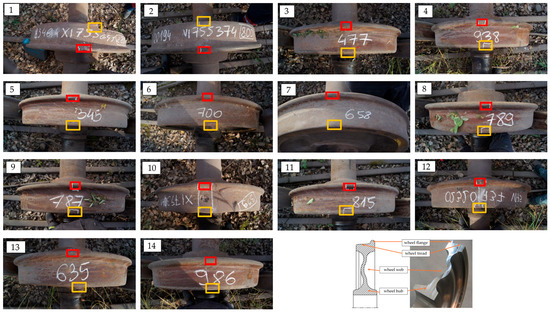
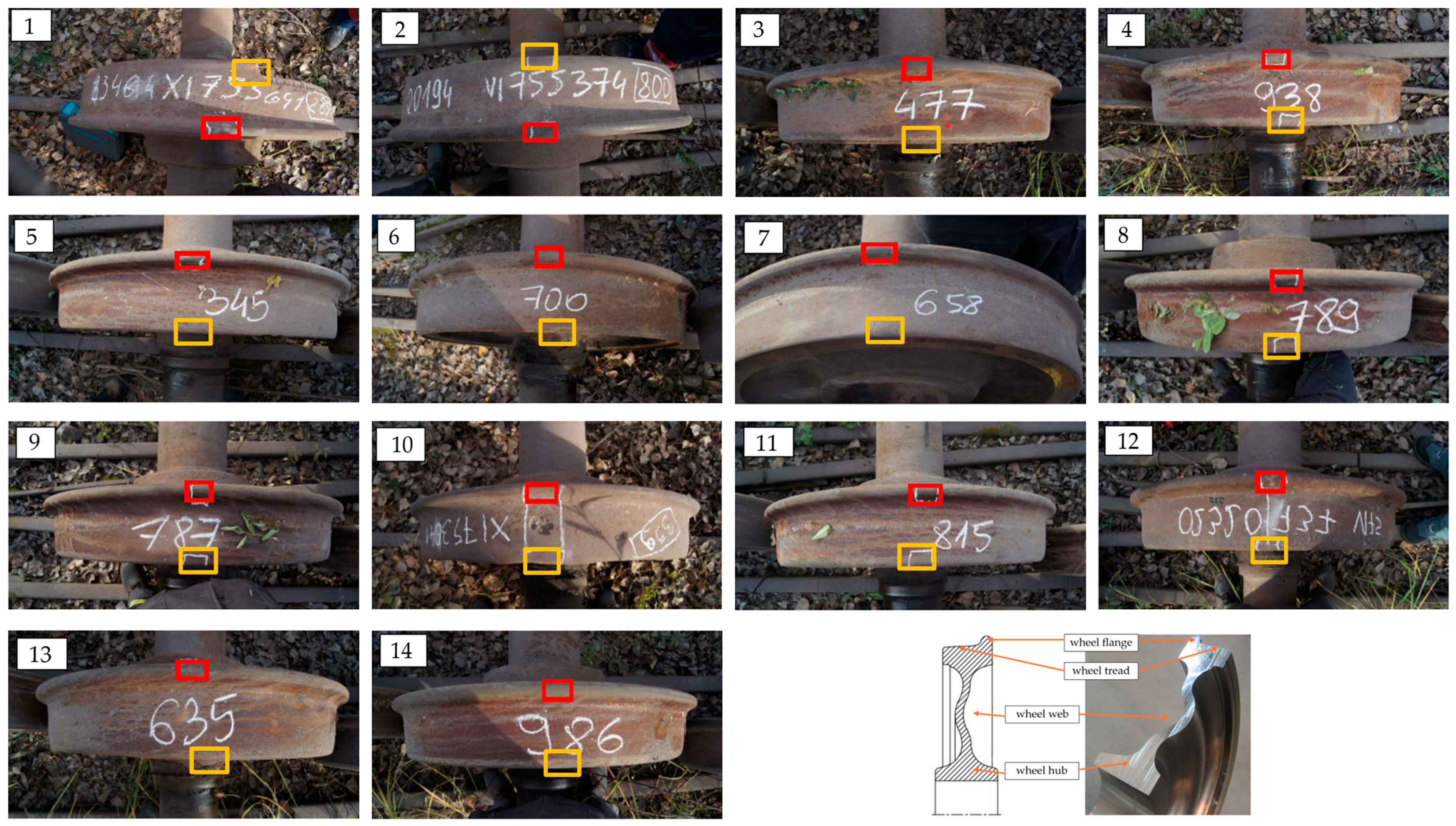
Figure 4.
The tested wheels with the marked areas of sample collection: red—wheel flange, yellow—wheel tread edge area. (1–14): wheel number.
Figure 4.
The tested wheels with the marked areas of sample collection: red—wheel flange, yellow—wheel tread edge area. (1–14): wheel number.
3. Results
3.1. Analysis of the Samples Taken from the Wheel Flange
3.1.1. Macroscopic Assessment of the Fraction of Areas Modified by Post Foundry Processing
Figure 5 shows macroscopic images of the samples cross sections with marked areas for chemical composition analysis (yellow line) and hardness measurements (red line). These macroscopic images enable an assessment of the volume fraction of areas modified as a result of post foundry processing of the tested samples. It can be noticed that samples 1, 2, and 10 exhibit the highest surface fraction of modified areas, while the macrostructure of samples 6 and 7 reveals an absence of welding treatments.
The assessment of the parent material of the cast pig iron wagon wheels was carried out on the basis of microstructural observations and hardness measurements within the area delineated by the red line (Figure 5). For this area, the chemical composition was analyzed using two methods (spark spectrometer and EDS). In order to verify the genesis of the microstructural changes, a control analysis of the chemical composition was performed in the areas limited by the yellow line.
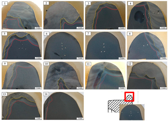
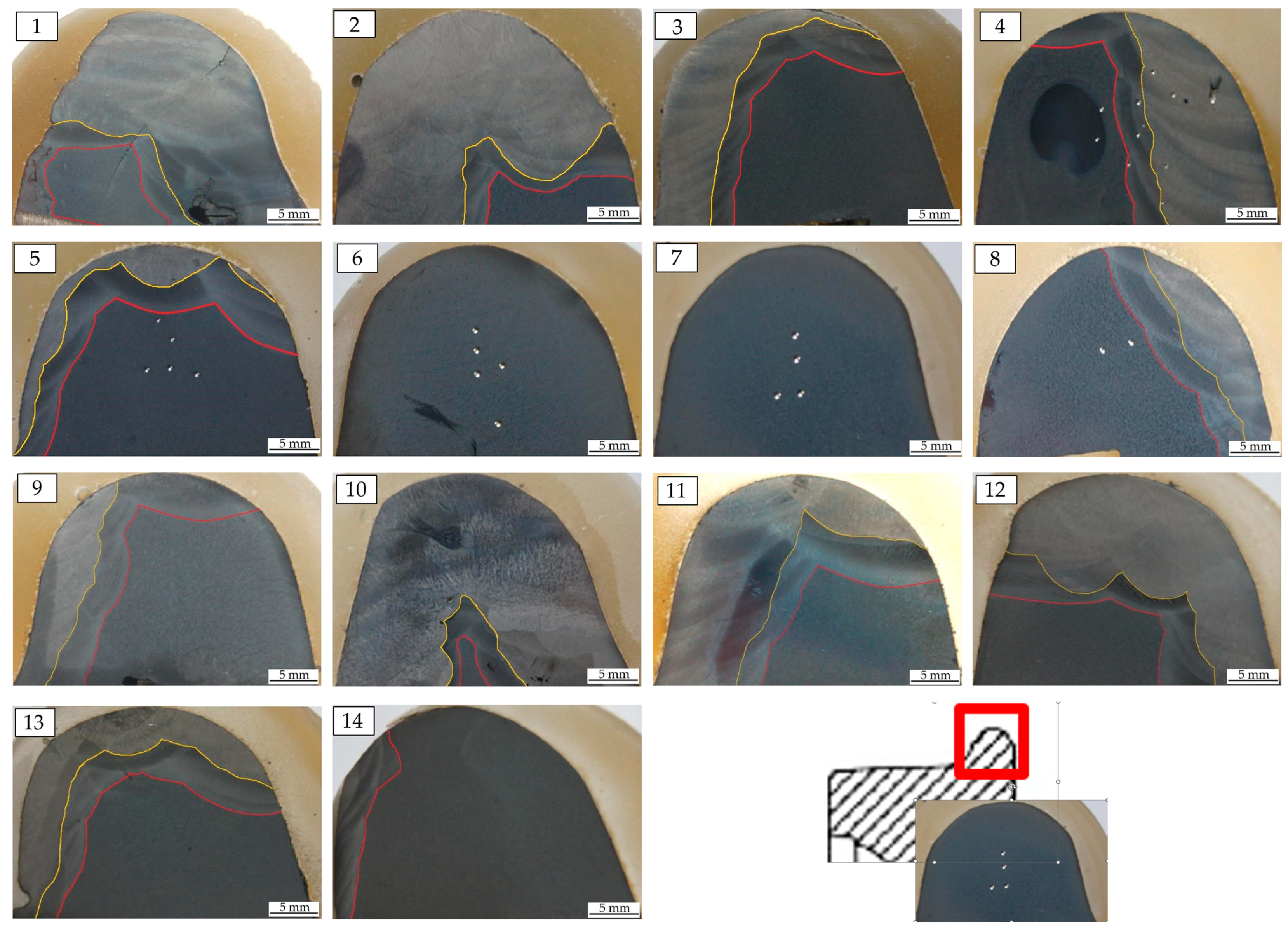
Figure 5.
Macro images of etched metallographic cross sections of the wheels flange with marked hardness test areas in the parent material (red line) and fusion line (yellow line). (1–14): wheel number.
Figure 5.
Macro images of etched metallographic cross sections of the wheels flange with marked hardness test areas in the parent material (red line) and fusion line (yellow line). (1–14): wheel number.
3.1.2. Chemical Composition Analysis
The average results of the chemical composition analysis of the parent material carried out with the spark spectrometer are presented in Table 1. It can be stated that the cast steel used is non-alloy cast steel with increased chromium content and carbon content, which is indicative of a hypoeutectoid cast steel. These cast steels can be classified within the range of materials from C45 through C50 to C55 (according to the UE classification system for unalloyed steels [31,32]). Nevertheless, based on the chemical composition results (Table 1) and the verification of areas with a modified structural character, three known steel grades were selected. The material in these areas can be classified as 100CrMn6 (in most cases), 38MnSi4, and in one case, P355NL1. It should be noted that deficiencies in the production process of cast steel monoblock wheels can be filled through the welding process. The described macrostructure of the samples is most likely the result of repair processes used in the production of cast steel monoblock wheels [22,23,24].

Table 1.
Chemical composition of the parent material (Foundry-Master WAS spectrometer).
The chemical composition of the matrix was verified using a scanning electron microscope. The results of this analysis are presented in Table 2. It should be noted that the chemical composition assessment using a scanning electron microscope did not take into account the content of carbon and other microadditives and impurities. Consequently, the results indicate an average higher content of silicon, manganese, and chromium compared to the analysis performed using a spark spectrometer. However, it should be noted that this will not have a significant effect on the comparative analysis of alloy element content but rather will only affect the absolute amount. When comparing the results of chemical composition analyses in this way, there is not always a correlation between the contents of individual elements. Nevertheless, it can be hypothesized that the assessment of alloy elements performed using a scanning electron microscope more closely corresponds to the qualitative differences in the chemical composition of the matrix of the tested cast steels.
Table 2.
Chemical composition of the parent material (Scanning Electron Microscope Phenom XL).
3.1.3. Microstructural Analysis
The microstructure of the parent material of the cast monoblock wheel tested, documented using a light microscope, is shown in Figure 6. The analyzed microstructure corresponds to a hypoeutectoid cast steel. A network of ferrite precipitates is visible along the grain boundaries of the former primary austenite. In some cases, some of the ferrite precipitations are similar to the Widmanstätten structure, indicating accelerated cooling in the temperature range of ferrite precipitation from austenite (Figure 6(1,6,12)). In certain cases (Figure 6(14)), the morphological characteristic of the matrix clearly suggests the presence of pearlitic structure. The characteristic lamellar arrangement of ferrite and cementite for the eutectoid in iron alloys is visible, but it was often difficult to observe lamellar patterns in most cases.
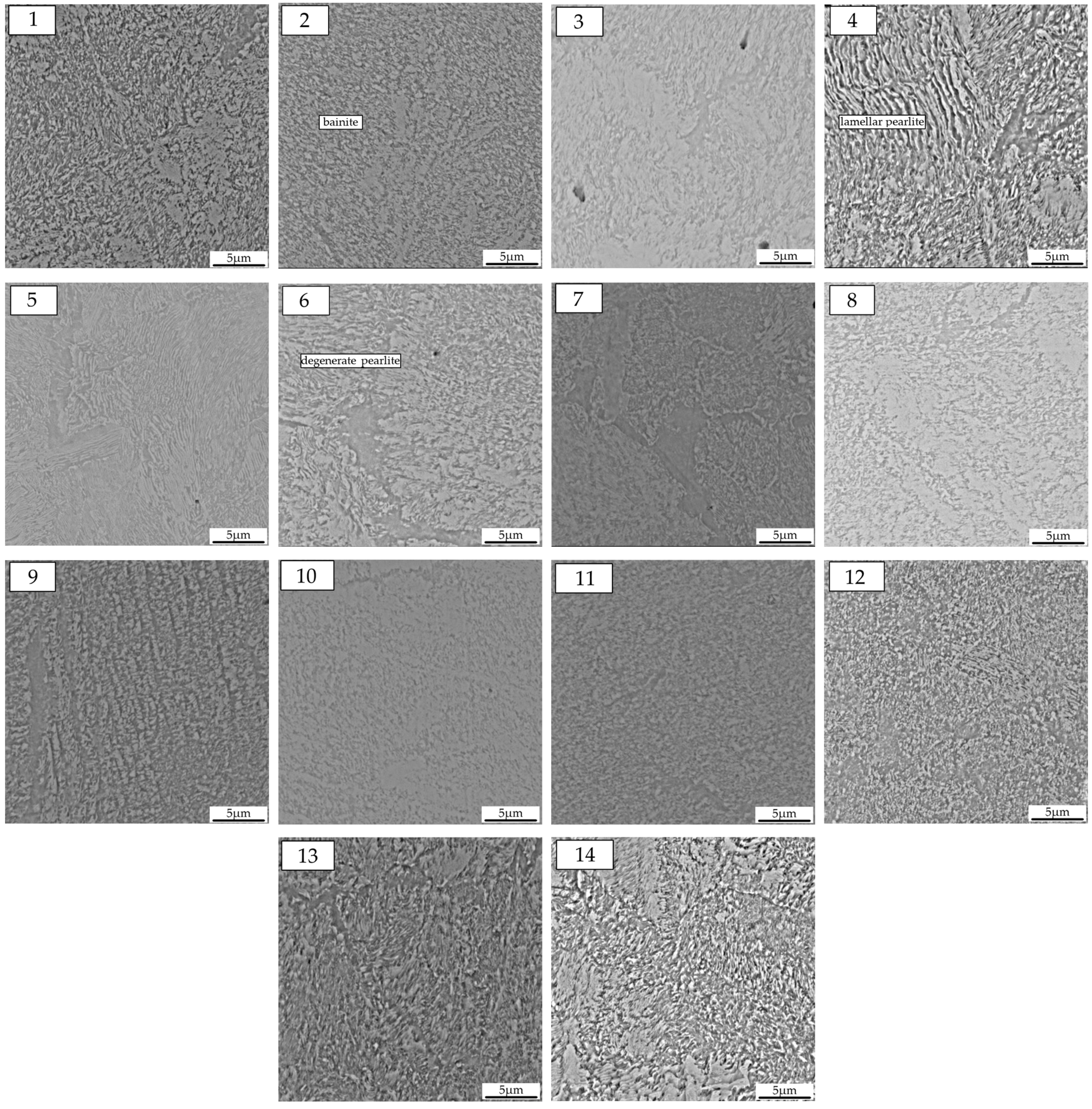
In order to gain a more accurate visualization of the matrix of the study materials, it was decided that observations would also be performed using a scanning electron microscopy (SEM). The matrix microstructure of the parent material in the tested pig iron wagon wheels exhibited significant differences in some cases. There are cases where the matrix is more similar to bainitic structures (Figure 7(2,3,10,11)). These findings indicate that the wheels may have undergone accelerated cooling during the crystallization or heat treatment process.

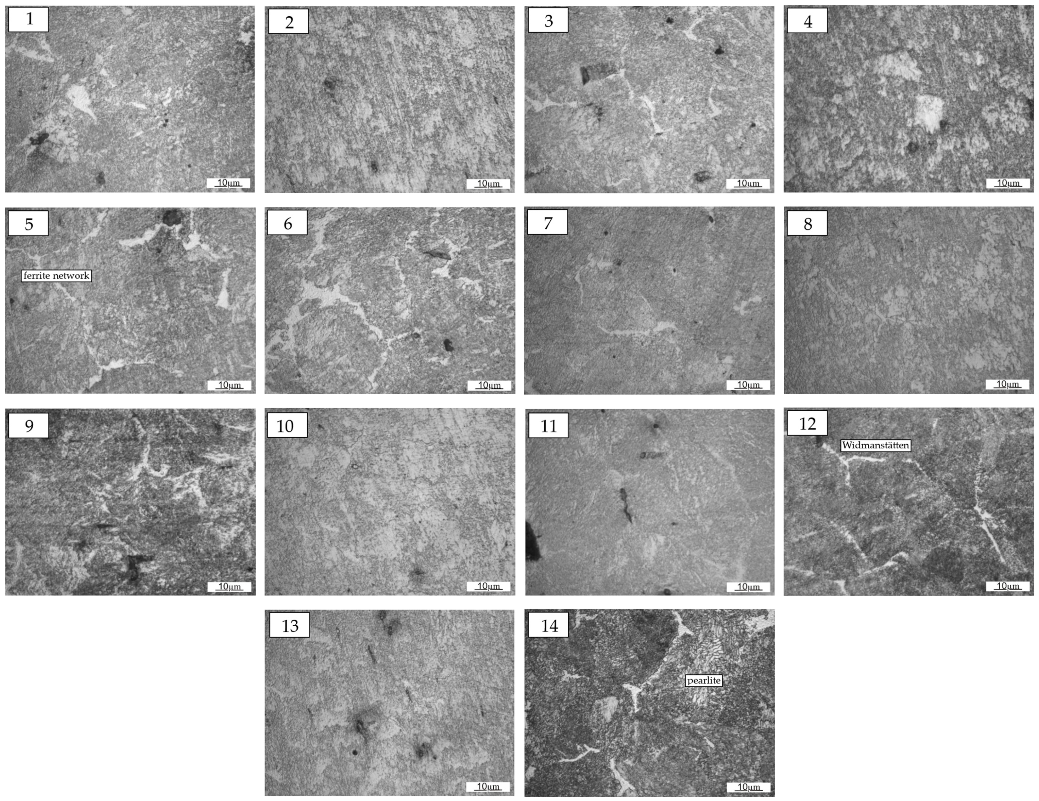
Figure 6.
Microstructure of the cast steel parent material used for the production of monoblock wheels. (1–14): wheel number.
Figure 6.
Microstructure of the cast steel parent material used for the production of monoblock wheels. (1–14): wheel number.

Figure 7.
Microstructure of the parent material of monoblock wheels, SEM. (1–14): wheel number.
3.1.4. Quantitative Evaluation of Macro and Microstructural Characteristics
Further insight was gained through calculations of the fraction of modified areas (post-casting), the area of primary austenite grains, and the ferrite volume fraction; the results of the tests are presented in Table 3. Hardness measurements were made in the parent material, with the obtained results falling within the range of 257 to 297 HV30 (Table 3). It should be noted that assuming the hardness of railway rails to be approximately 300 HB (303HV30), the materials used for the pig iron wagon wheels should exhibit a marginally lower hardness. Therefore, it can be assumed that the hardnesses of the tested wheels are in alignment with the assumed requirements [8].
Table 3.
Results of quantitative analysis of macro and microstructure morphological features.
3.2. Analysis of Samples Collected from the Wheel Tread Edge Area
3.2.1. Macroscopic Evaluation of the Prevalence of Typical Welding Zones
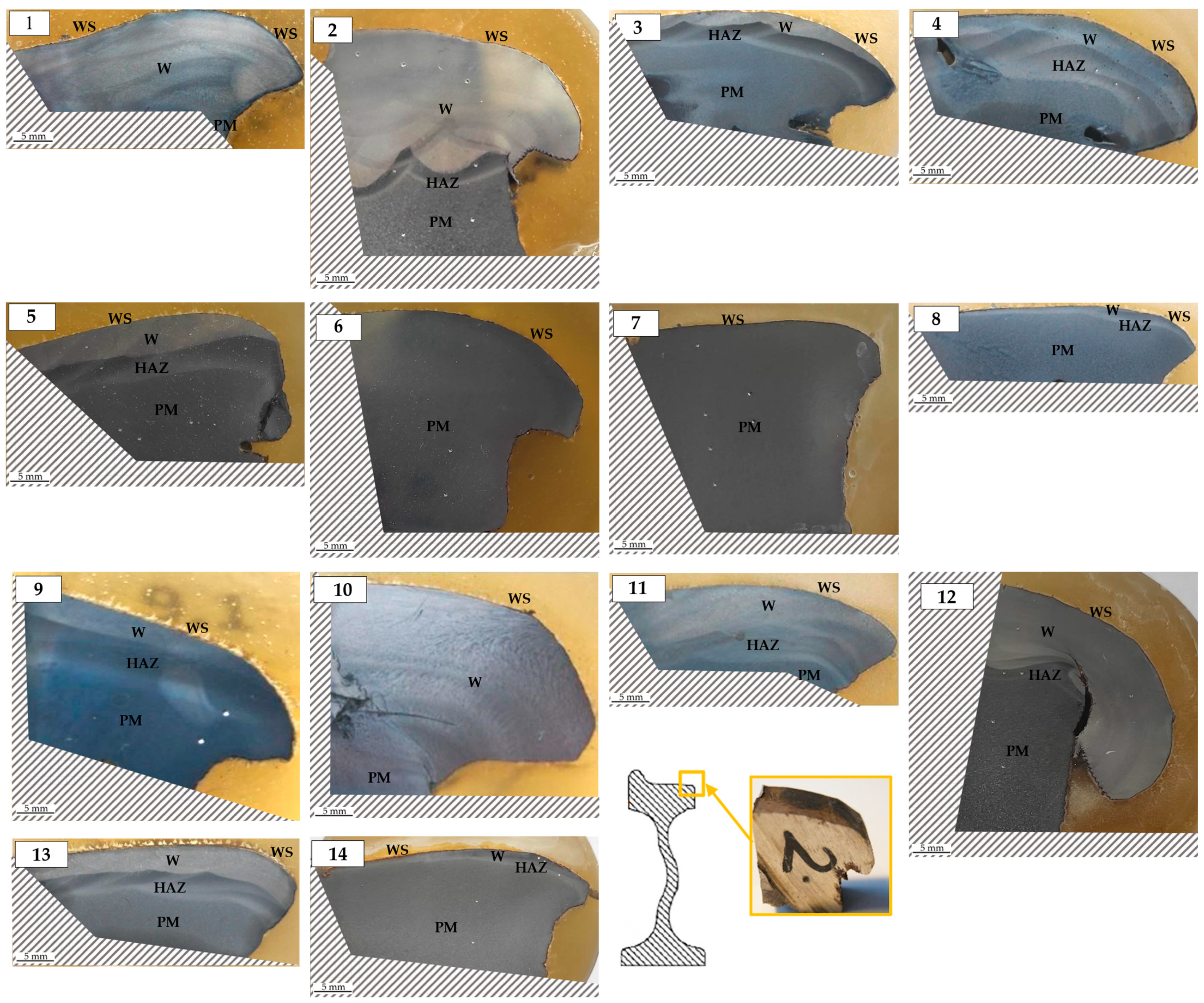
Figure 8 presents macroscopic images of fourteen metallographic sections with the marked working surface (WS). Differences in the degree of etching of the samples allowed a preliminary identification of the weld zones, i.e., the padding weld (W), the heat-affected zone (HAZ), and the parent material (PM). Subsequently, these areas were later tested for chemical composition and hardness. A visual evaluation of the metallographic sections indicates that samples taken from wheels No. 1, 2, 4, 10, and 11 exhibit the highest volume fraction of areas considered to be padding welds, while samples from wheels No. 6 and 7 may indicate the absence of welding.
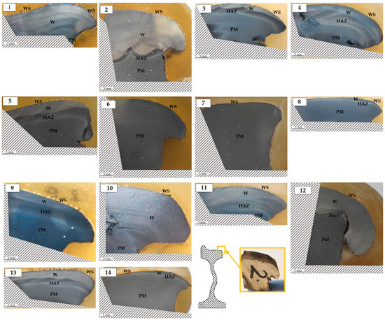
Figure 8.
Macro image of etched metallographic sections with marked areas: W—weld, HAZ—heat-affected zone, PR—parent material, WS—working surface. (1–14): number of the wheel.
3.2.2. Chemical Composition Test Results
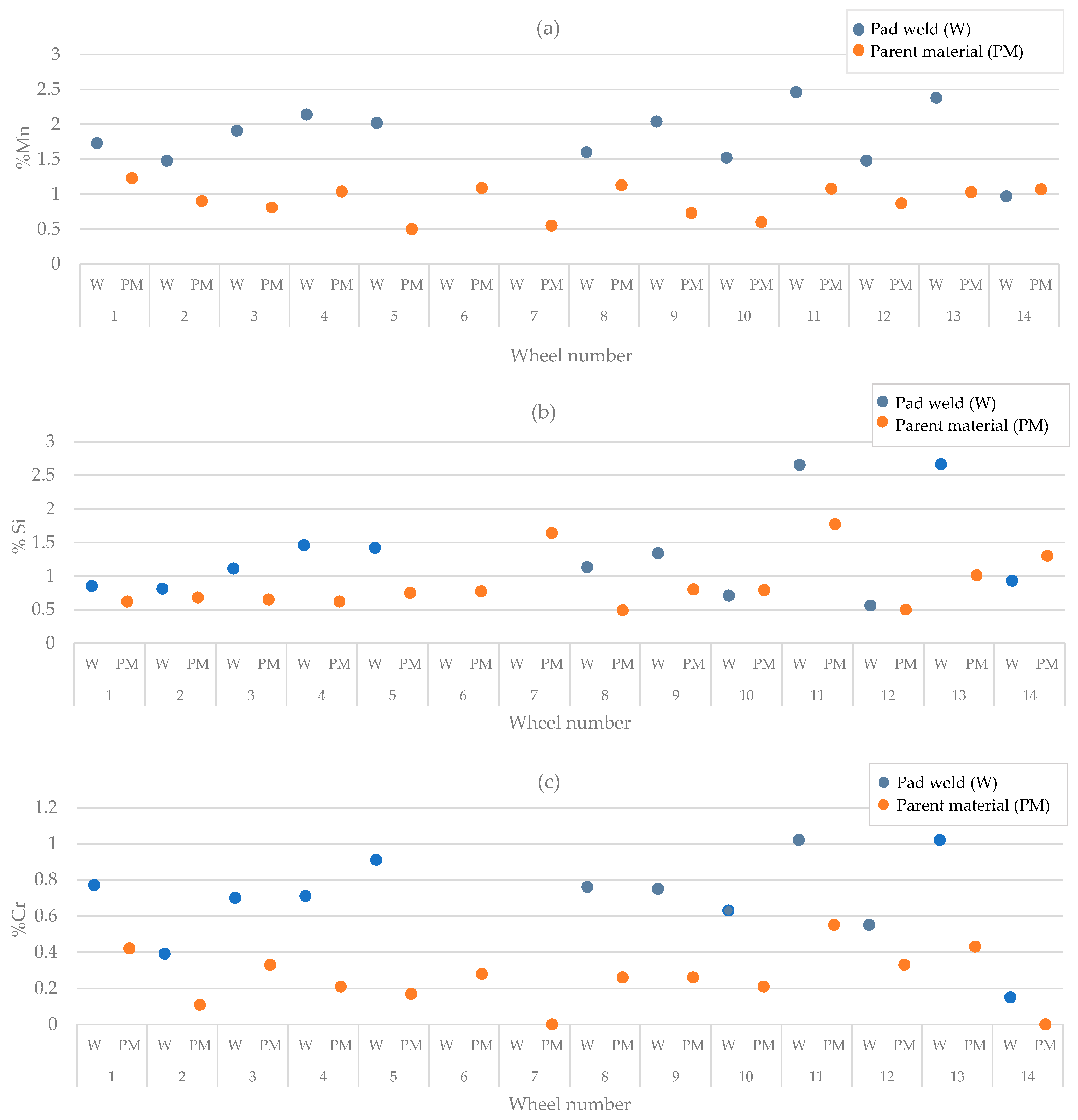
The chemical composition of the parent material of the undeformed areas of the wheel (i.e., the flange) was obtained using a spark spectrometer (Table 1). The results of this analysis determined that the monoblock wheels were made of hypoeutectoid unalloyed cast steel [29,30]. The chemical composition of samples taken from the wheel tread edge area was examined using an EDS (Energy Dispersive Spectroscopy) analysis in a scanning electron microscope, and the obtained results were presented in the Table 4 and the form of graphs (Figure 9) showing the contents of the given elements in the adopted padding weld and parent material. Analyzing Figure 9 reveals that, in most of the samples, the content of alloying elements in the adopted padding weld is higher than in the parent material. This finding suggests the possibility of the use of additional material during the welding process.
Table 4.
Chemical composition of the parent material (PM) and the weld (W) in samples taken from the wheel tread edge area (Scanning Electron Microscope Phenom XL).
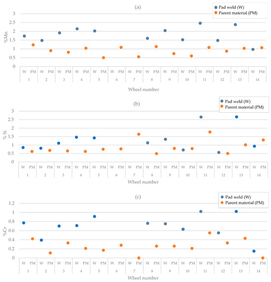
Figure 9.
Contents of manganese (a), chromium (b), and silicon (c) in the areas adopted in accordance with Section 3.2.1: weld (W), parent material (PM).
3.2.3. Microstructural Analysis
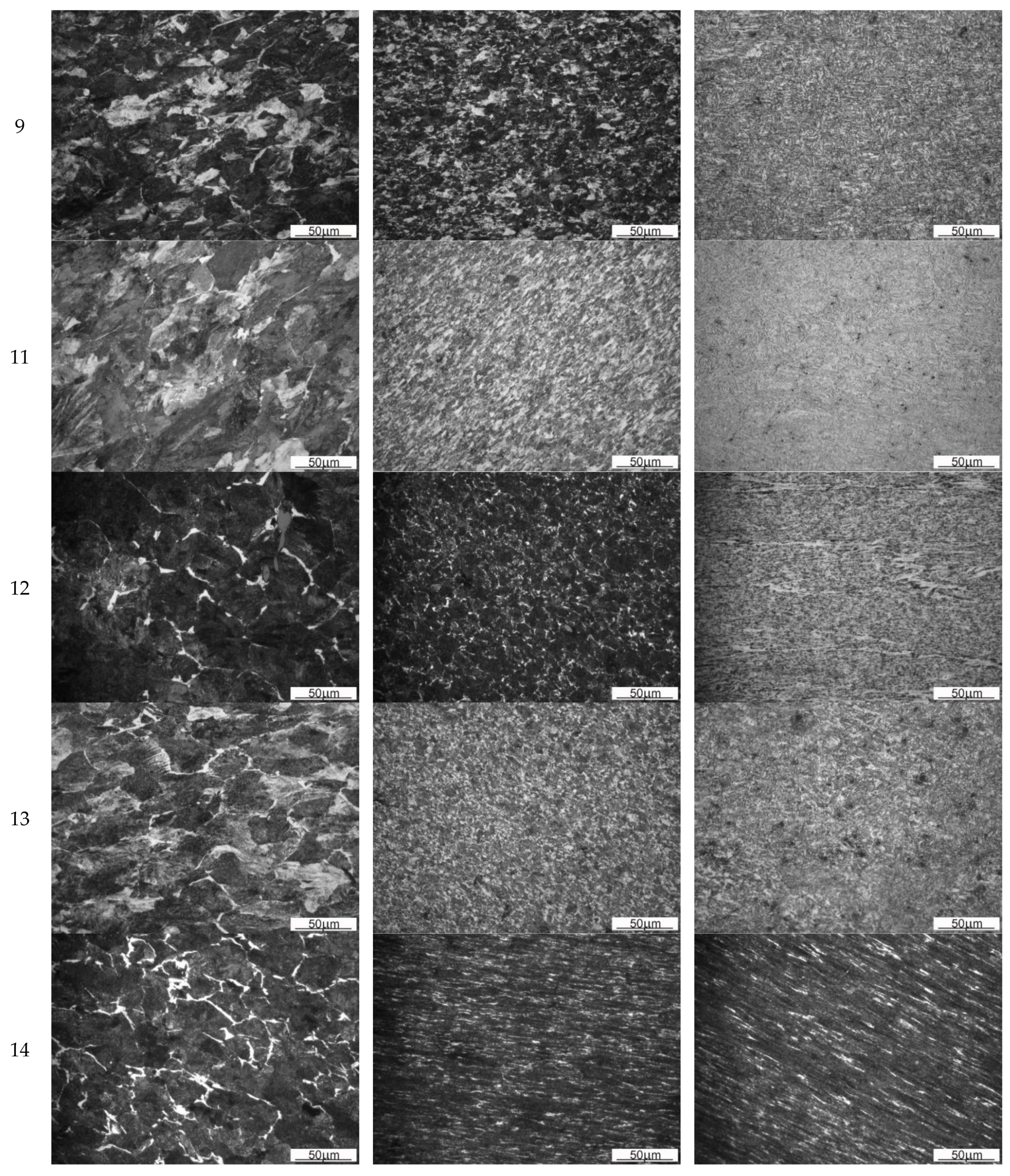
Microstructural documentation was prepared with a light microscope for the zones adopted in Section 3.2.1 and was presented in Figure 10.
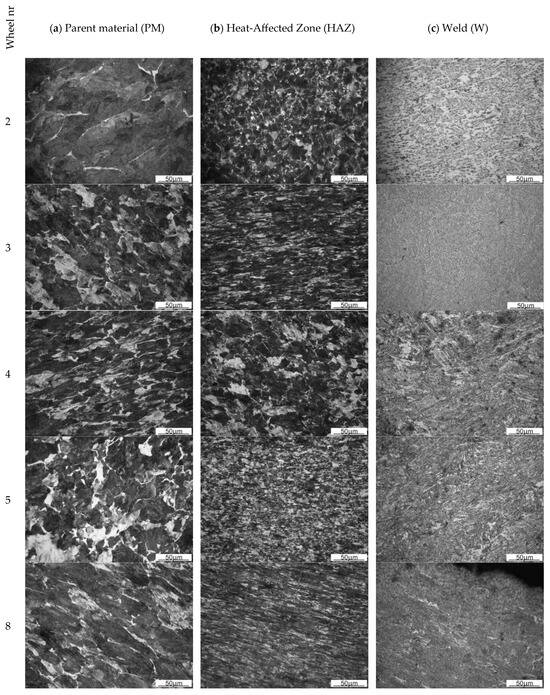
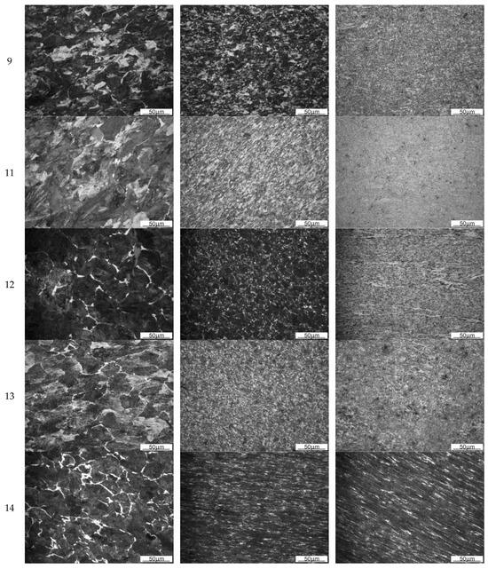
Figure 10.
Microstructure of selected wheels: parent material (a), heat-affected zone (b), and weld (c).
In the case of the materials tested, the microstructure of the material in the surface area is characterized by a distinct igneous morphology. The character of the microstructure of the surface varies for the different monoblock wheels tested. It is possible to observe samples characterized by a significantly larger needle size (Figure 10(4c)) and materials with a significantly finer microstructure (Figure 10(11c)). The observed differences are also significantly influenced by the plastic deformation of the material about its service life. This is particularly evident in the case of wheel 14 (Figure 10(14c)).
The microstructure of the parent material and the heat-affected zone corresponds to the pearlitic-ferritic structure (e.g., Figure 10(4a,b)). At the grain boundaries of former austenite, a lattice morphology of ferrite precipitates is also observed (e.g., Figure 10(14a)). In the regions where the padding weld is identified, the typical for this process bainitic feathery structure (e.g., Figure 10(11c)) and the bainitic structure of acicular nature (e.g., Figure 10(4c)) are observed. In the weld area of sample 12, in addition to bainite, a small fraction of fine pearlite can be seen (Figure 10(12c)). The initial interpretation of the areas of sample 14 as characterized by the presence of a padding weld is thus rather attributed to differences in the intensity of plastic deformation and thermal impact resulting from friction as a result of operation. In the weld area, a columnar structure with marked interdendritic spaces and a strongly deformed columnar structure, characteristic of the crystallization process, is visible. In places of strong deformation, a tendency for grains to elongate in the direction of plastic flow of the material was also observed (Figure 10(4c)).
A comparison of the grain size in the parent material and in the heat-affected zone reveals that, in the area created after the welding process, there is a smaller grain size. This phenomenon may be the result of recrystallization of the structure. The prepared documentation clearly shows that the degree of plastic deformation of the material decreases as it moves from the working surface into the volume of the bare wheel. This indicates that the process of plastic material flowing towards the free (side) surface of the wheel contributes significantly to the wear of bare wheels. Therefore, the properties of the parent material and the padding weld should be shaped to strengthen the material in order to resist the loss of stability to a greater extent than resistance to abrasive wear, and the rheological parameters of the padding should be considered correctly.
3.2.4. Hardness Measurement
Hardness measurements were made for each area specified in Section 3.2.1. i.e., the weld (W), the heat-affected zone (HAZ), and the parent material (PM). Analysis of the results obtained (Table 5) shows that the hardness for the assumed areas is within the following ranges: 240–430 HV30 for the weld; 230–400 HV30 for the heat-affected zone; 260–320 HV30 for the parent material.
Table 5.
Hardness measurement results (HV) for parent material, heat-affected zone, and weld.
For most samples, hardness decreases from the weld through the heat-affected zone to the parent material. The values obtained for the areas created by the welding process, which reach over 350 HV, may indicate that the non-diffusion transformation of austenite to bainite has occurred during crystallization. Strain hardening due to wear can also be responsible for increased hardness in the weld area.
4. Discussion
4.1. Effect of Chemical Composition on Microstructure and Hardness
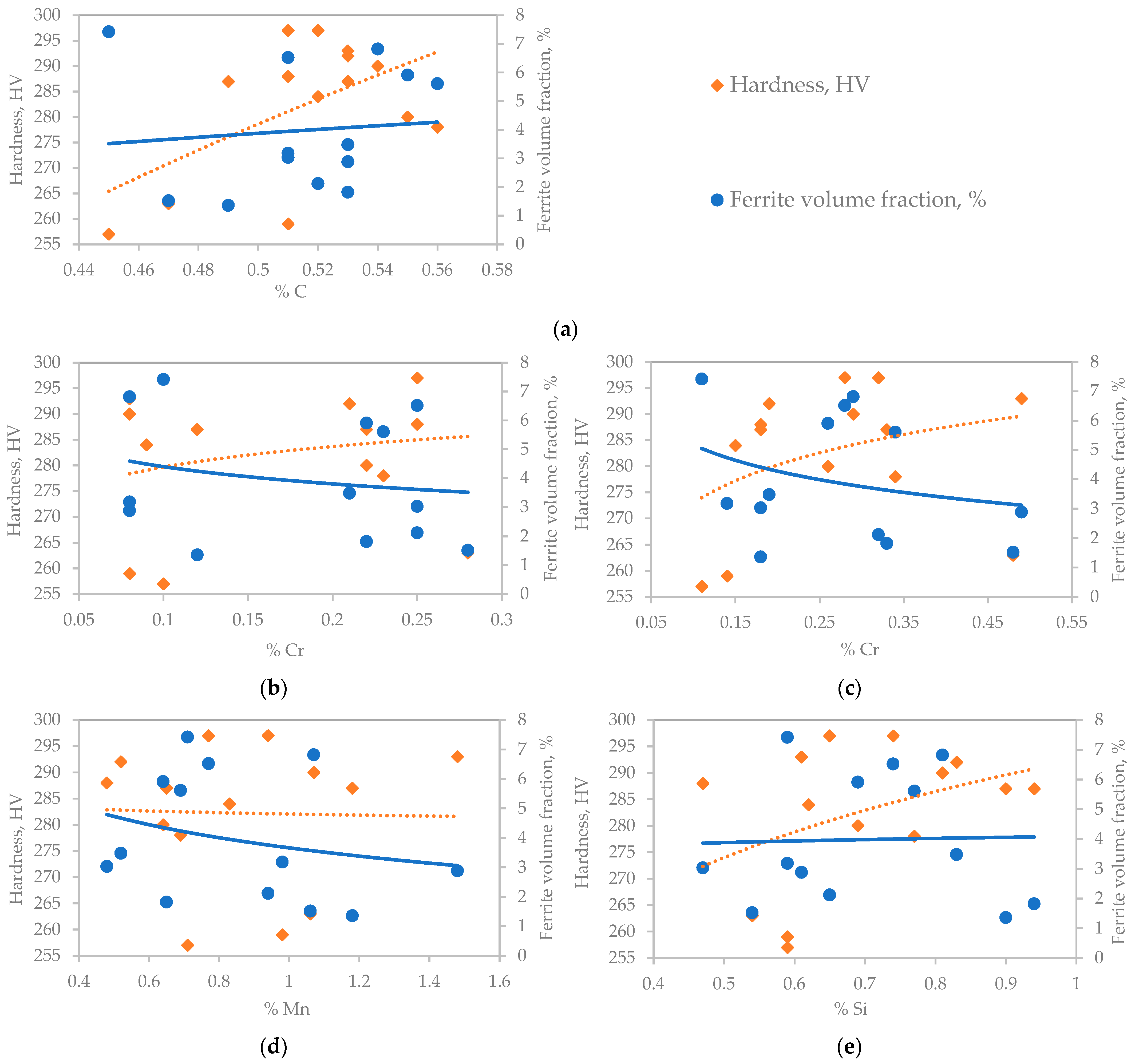
Figure 11 shows the effect of chemical composition on hardness. Utilizing a spark spectrometer, the results presented in Figure 11a,b were obtained, while the results depicted in Figure 11c–e were obtained through the implementation of EDS analysis. The observations indicate that the hardness of the material exhibits an increase in correlation with the elevated carbon content. Therefore, the volume fraction of ferrite should be expected to decrease as the carbon content increases, but the results show an inverse relationship. An increase in hardness and a decrease in the volume fraction of ferrite with increasing content of alloying elements such as Cr, Mn, and Si would be expected. Only the effect of manganese on hardness is not consistent with the above assumption from the results presented.
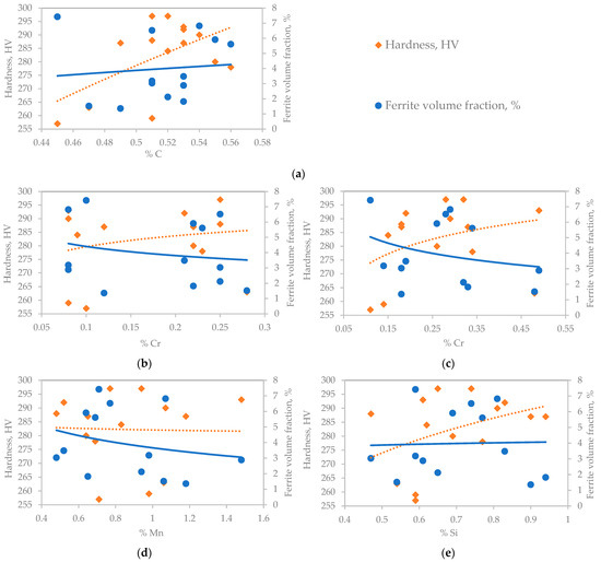
Figure 11.
Dependence of hardness and ferrite volume fraction on: carbon content obtained on spark spectrometer (a), chromium content obtained on spark spectrometer (b), chromium content from EDS analysis (c), manganese content from EDS analysis (d), silicon content from EDS analysis (e).
4.2. Influence of Microstructure on Hardness
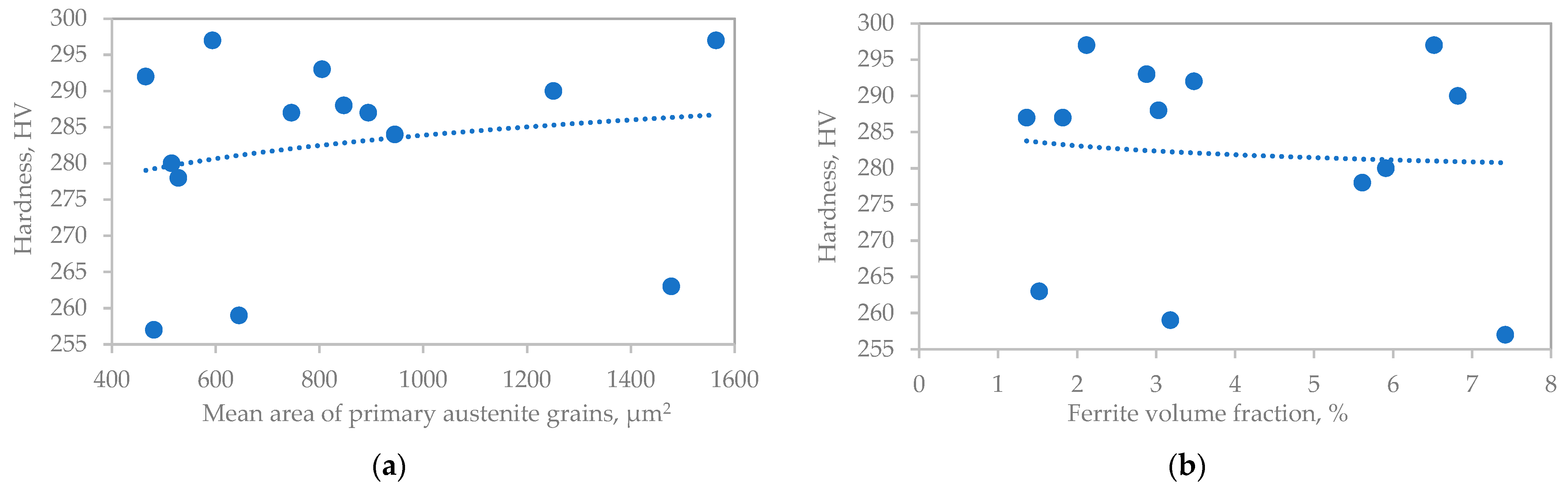
Figure 12a illustrates the relationship between the mean area of primary austenite grains and material hardness, whereas Figure 12b presents the correlation between hardness and ferrite volume fraction. The data indicate a tendency for hardness to increase with an increase in the mean cross-section area of primary austenite grains and to decrease with an increase in the ferrite volume fraction.
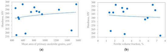
Figure 12.
Dependence of hardness on: the cross-sectional area of primary austenite grain (a), ferrite volume fraction (b).
4.3. Analysis of the Correctness of the Assumptions Regarding the Occurrence and Nature of the Weld, the Heat-Affected Zone, and the Parent Material
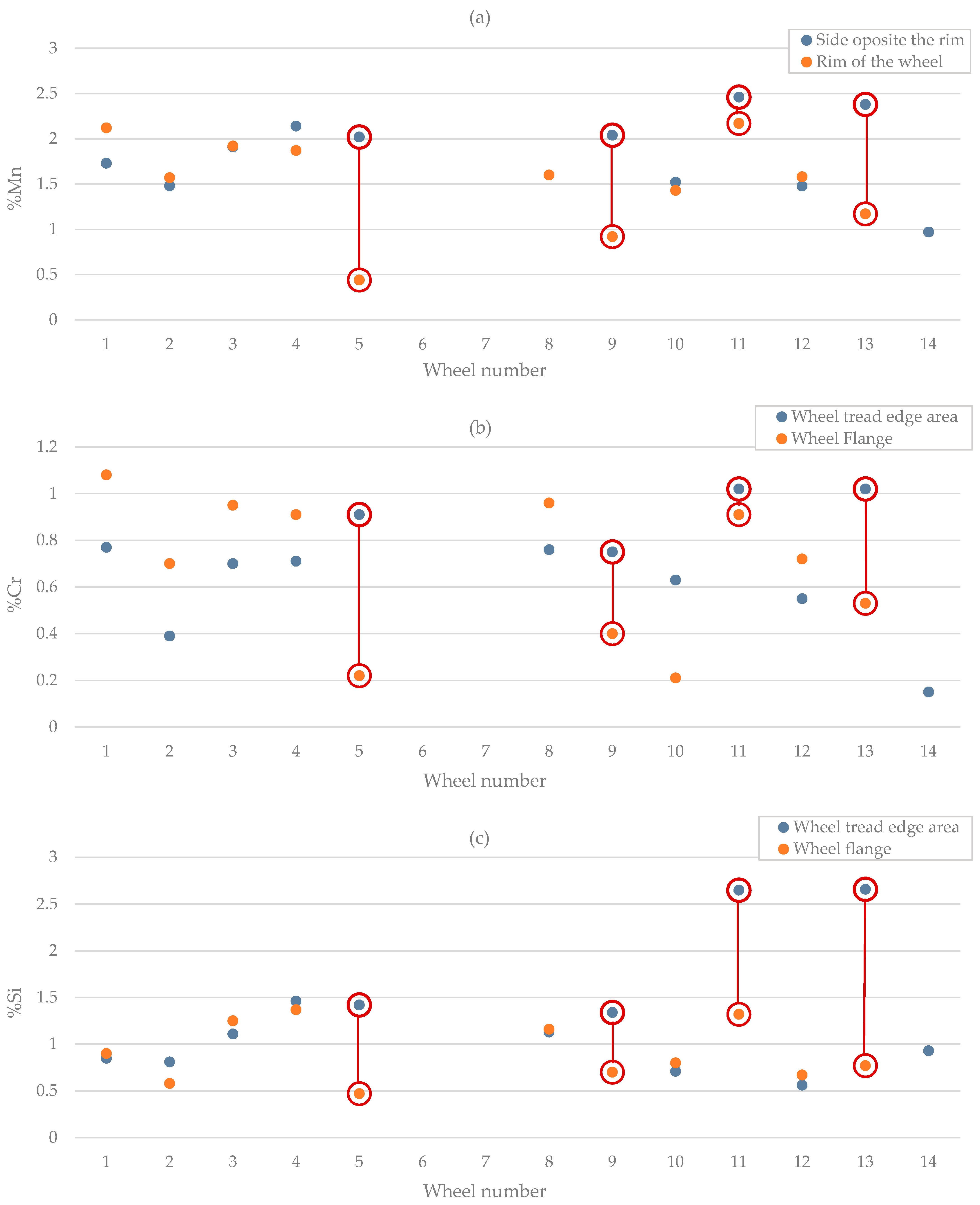
Macroscopic observations of samples taken from the wheel flange no. 1–5 and 8–13 are characterized by the so-called area modified as a result of post-casting processing (Figure 8). Most likely, these are places where casting defects were repaired by welding. To select regenerative weld (RW), the obtained contents of manganese, silicon, and chromium of samples taken from the wheel tread edge area were compared with the measurement values of samples taken from the flange (Figure 13). Preliminary analysis showed that samples taken from the treat edge area from wheels 1–4, 8, 10, and 12 most likely contain only foundry weld (W). Differences in chemical composition can be seen for samples from wheels 5–7, 9, 11, 13, and 14, which may indicate that the welding was carried out only after the wheels (RW) were worn out. These assumptions were confirmed by microstructural documentation for samples from wheels 5, 9, 11, and 13 (Figure 10). Wheels 6 and 7 were rejected based on previous macroscopic observations that indicated no welding was used (Figure 8). In the microstructural documentation for the sample from wheel nr 14, a microstructure characteristic of the parent material was observed (Figure 10). The low hardness also confirmed that the welding process was not applied to wheel 14, and thus, the analysis will be focused on samples from wheels 5, 9, 11, and 13.
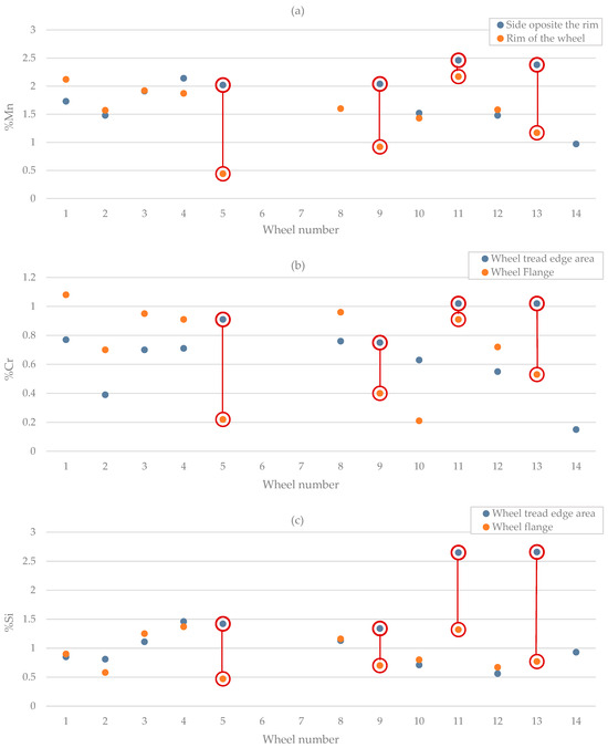
Figure 13.
Contents of manganese (a), chromium (b), and silicon (c) in the modified area for samples taken from the flange and in the assumed pad weld for samples taken from the tread edge area.
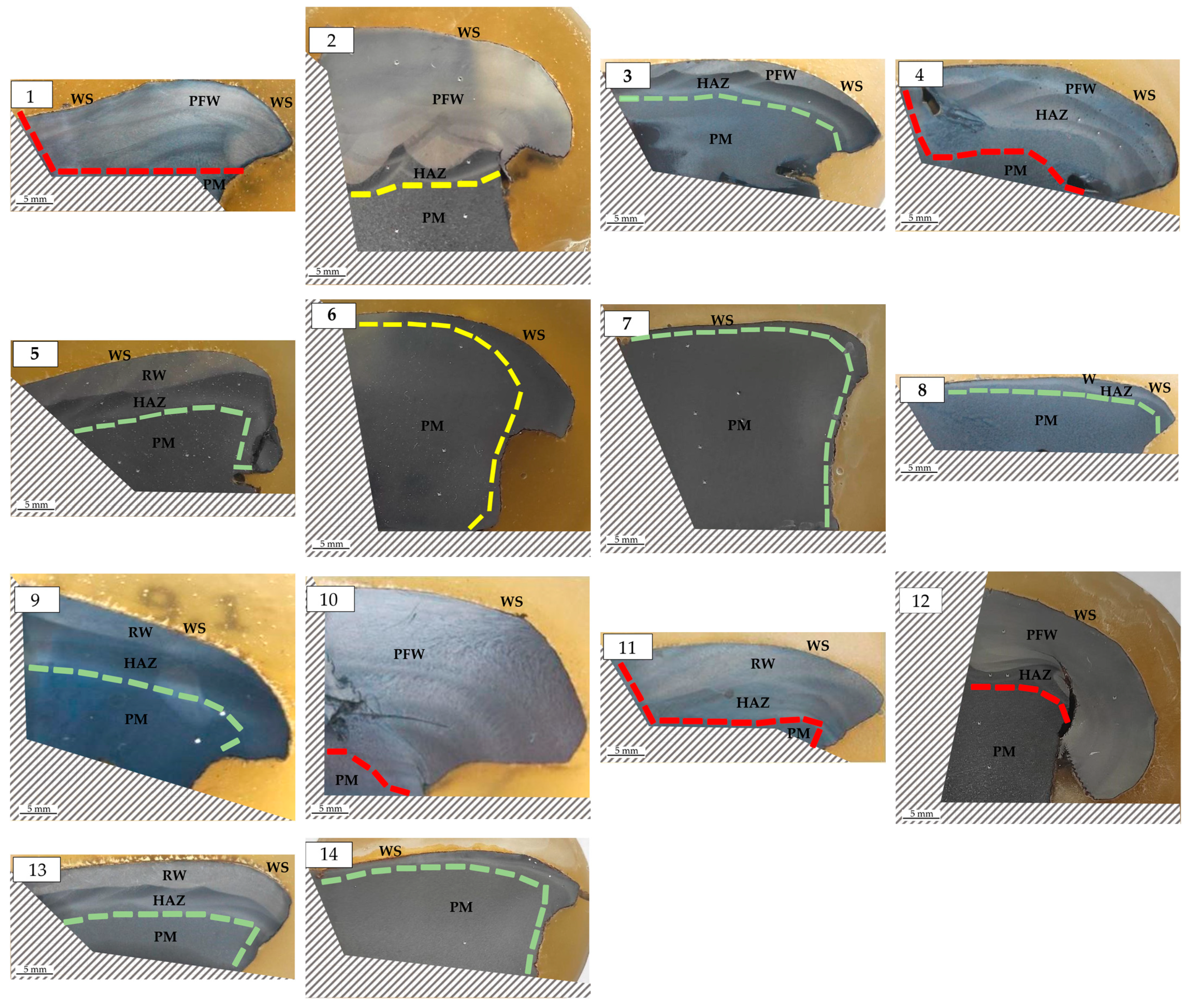
Figure 14 shows the welding zones along with the parent material after a comprehensive analysis, including chemical composition, microstructure, and hardness. Based on macro- and microstructural observations, each sample was also classified according to the degree of deformation (large, medium, small).
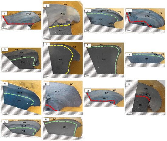
Figure 14.
Macro image of etched metallographic sections with marked deformation degree (large deformation—red line, medium deformation—yellow line, small deformation—green line) and areas: repair weld (RW), post foundry weld (PFW), heat-affected zone (HAZ), parent material (PM), working surface (WS). (1–14): wheel number.
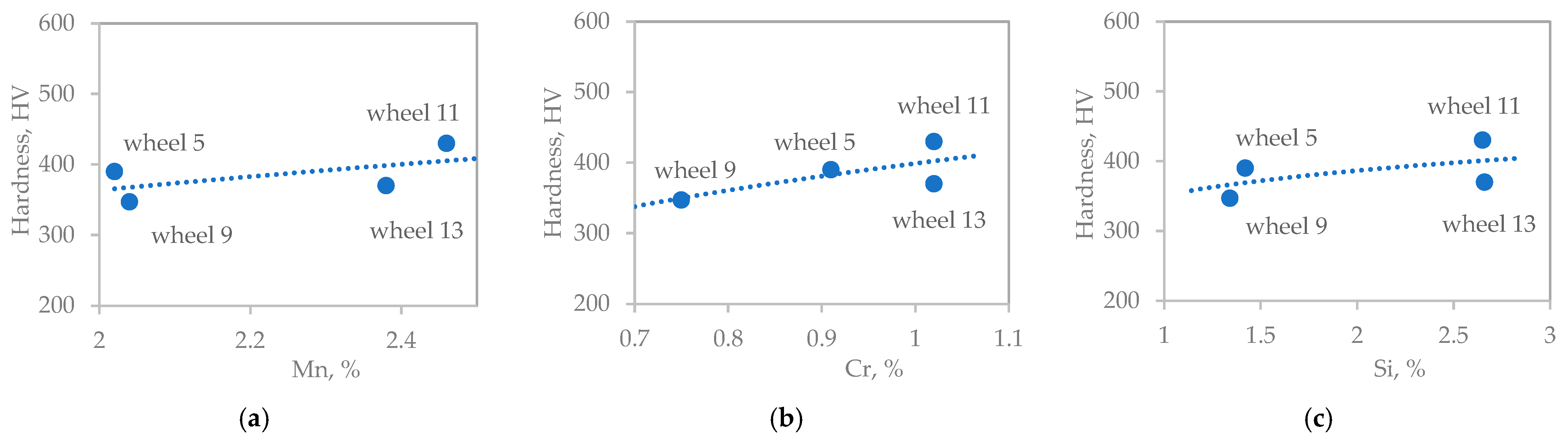
4.4. Influence of Chemical Composition on Weld Hardness
Figure 15 illustrates the impact of chemical composition on the hardness of the regenerative weld. There is a modest tendency for the hardness of the tested material to increase with increasing content of manganese, chromium, and silicon. This phenomenon can be attributed to the positive influence of Cr and Mn on the potential formation of banite, as well as the solid solution strengthening effect provided by silicon.
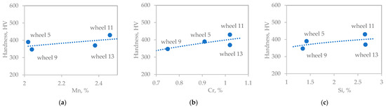
Figure 15.
Effect of manganese (a), chromium (b), and silicon (c) on the weld hardness.
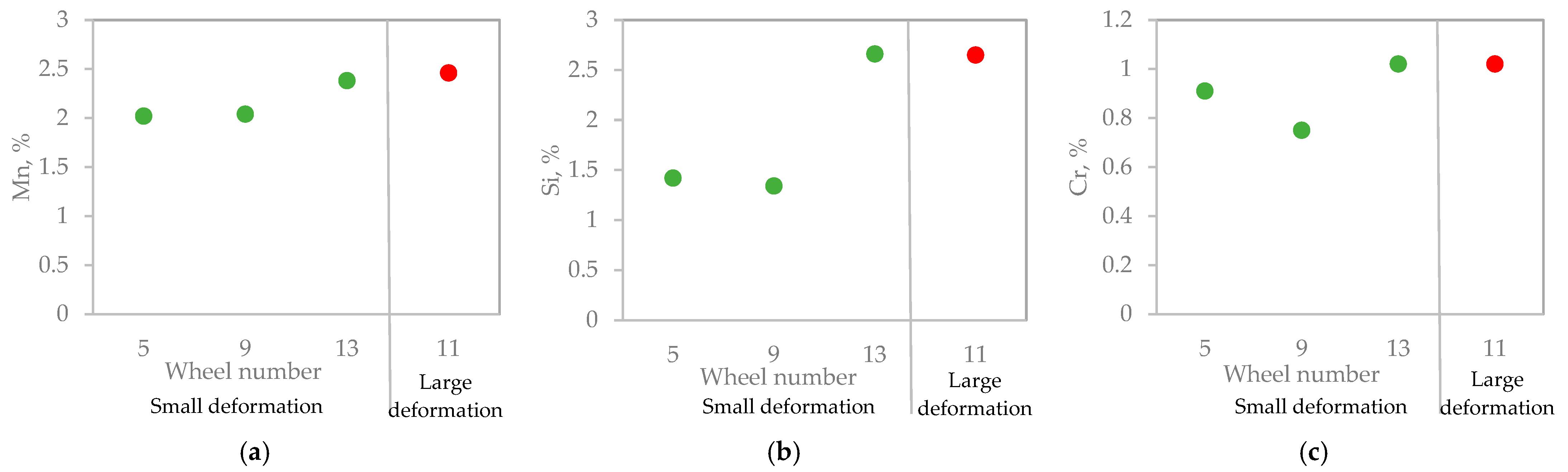
4.5. Relationship Between Chemical Composition and Deformation Degree
Figure 16 shows the dependence of the degree of deformation on the content of manganese, chromium, and silicon. It can be seen that elevated concentrations of these elements correspond to higher deformation, a phenomenon that is influenced by numerous factors. This is most likely attributed to the fact that manganese, chromium, and silicon reduce the material’s susceptibility to abrasive wear and increase the tendency to wear through plastic flow.
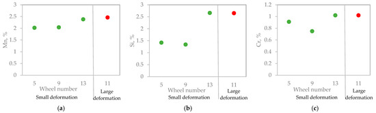
Figure 16.
Effect of manganese (a), chromium (b), and silicon (c) on the repair weld deformation degree (large deformation—red dots, small deformation—green dots).
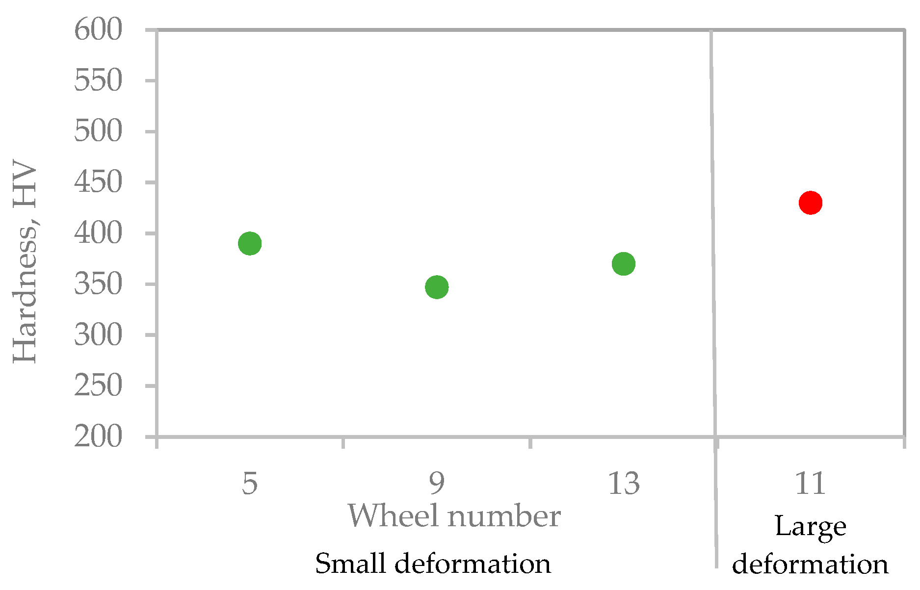
4.6. Influence of Deformation Degree on Hardness
The influence of the deformation degree of the regenerative weld on its hardness is shown in Figure 17. It can be seen that the hardness values correspond to a higher deformation degree, which can be related to the so-called deformation strengthening. The material strengthens due to the slip of dislocations on intersecting slip planes. The accumulation of dislocations at these specific locations leads to a decrease in ductility, accompanied by an increase in strength and hardness.
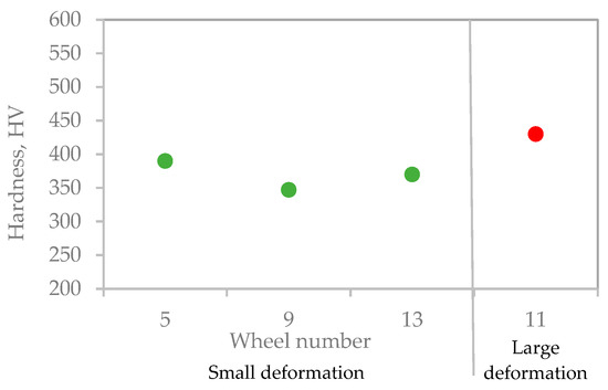
Figure 17.
Effect of repair weld deformation degree on hardness. (large deformation—red dots, small deformation—green dots).
5. Conclusions
The findings of the research and analysis conducted allow for the following conclusions to be drawn:
- It was discovered that padding welds were conducted at two distinct stages: initially, during the repair of bare wheel castings, and subsequently, following the completion of post-operation repairs.
- The microstructure of the weld is predominantly bainitic.
- The primary mechanism of wear observed in bare wheel components, both in the vicinity of welds and in the parent material, is the plastic flow of the material. It resulted in a change in the geometry of the wheel tread edge area, making further operation of the wheel impossible. Plastic flow occurred towards the free surface, and the presence of regenerative welds in the area of the wheel working surface may indicate earlier wear of the wheels due to the fatigue mechanism. Cracking was initiated on the surface or just below the surface in the area of the maximum shear stress (Hertz), and these cracks most likely resulted in defects that were filled by surfacing.
- The hardness of the material is dependent upon the chemical composition, the microstructural components, and the degree of plastic deformation.
- The addition of alloying elements results in increased hardness;
- The formation of non-equilibrium structures (bainite) also results in increased hardness;
- The observed increase in hardness is a consequence of strain hardening due to exploitation.
- Increasing the alloyability as a result of the padding weld helps to achieve greater plasticity of the material.
- The proposed methodology for analyzing the research results enables the drawing of conclusions regarding the origin of the padding weld (repair of castings and regeneration after operation). It allows us to distinguish the results of repair processes of wear effects in a highly loaded friction node with unsteady lubrication conditions (environmental influence) from repair processes applied to castings of large construction components.
Author Contributions
Conceptualization. J.K.; methodology. Ł.F.; investigation. Ł.F. and J.K.; writing—original draft preparation. P.M.; writing—review and editing Ł.F and P.M.; supervision J.K.; validation, Ł.F. and P.M. All authors have read and agreed to the published version of the manuscript.
Funding
The research was financed by the Ministry of Education and Science (AGH—research subsidy No. 16.16.110.663).
Data Availability Statement
Data are contained within the article.
Acknowledgments
The authors would like to thank Jagoda Kaptur and Elżbieta Dudek for their support with the research.
Conflicts of Interest
The authors declare no conflict of interest.
References
- Szudyga, M. Diagnostics of Fatigue by Magnetic Methods of Steel Used in Railway Wheels and Rims of Railway Wheel Sets. Ph.D. Thesis, Silesian University of Technology, Katowice, Poland, 2011. [Google Scholar]
- Zhou, H.; Zhang, H.; Yang, C. Hybrid-model-based intelligent optimization of ironmaking process. IEEE Trans. Ind. Electron. 2019, 67, 2469–2479. [Google Scholar] [CrossRef]
- Adilson de Castro, J.; Medeiros, G.A.d.; Oliveira, E.M.d.; de Campos, M.F.; Nogami, H. The Mini Blast Furnace Process: An Efficient Reactor for Green Pig Iron Production Using Charcoal and Hydrogen-Rich Gas: A Study of Cases. Metals 2020, 10, 1501. [Google Scholar] [CrossRef]
- Łędzki, A.; Zieliński, K.; Klimczyk, A. Basics of Manufacturing and Processing Technology. Part V. Steelmaking; AGH University of Kraków: Cracow, Poland, 2015. [Google Scholar]
- EN 13262:2020; Railway Application. Wheelsets and Bogies. Wheels. Product Requirements. European Standard: Brussels, Belgium, 2020.
- Available online: https://www.transportszynowy.pl/Kolej/zestawykolowe-kola (accessed on 30 November 2024).
- Zani, N.; Mazzù, A.; Solazzi, L.; Petrogalli, C. Examining Wear Mechanisms in Railway Wheel Steels: Experimental Insights and Predictive Mapping. Lubricants 2024, 12, 93. [Google Scholar] [CrossRef]
- Shi, Z.; Nencioni, L.; Meli, E.; Ding, H.; Wang, W.; Andrea, R. Effect of Material Hardness Ratio on Wear and Rolling Contact Fatigue: Development and Validation of New Laws. Wear 2023, 514–515, 204561. [Google Scholar] [CrossRef]
- Zhou, G.Y.; Liu, J.H.; Wang, W.J.; Wen, G.; Liu, Q.Y. Study on the fatigue and wear characteristics of four wheel materials. J. Mod. Transport. 2013, 21, 182–193. [Google Scholar] [CrossRef]
- Pointner, P. High strength rail steels—The importance of material properties in contact mechanics problems. Wear 2008, 265, 1373–1379. [Google Scholar] [CrossRef]
- Mendez, P.F.; Barnes, N.; Bell, K.; Borlea, S.D.; Gajapathi, S.S.; Guest, S.D.; Izadi, H.A.; Gol, K.; Wood, G. Welding processes for wear resistant overlays. J. Manuf. Process 2014, 16, 4–25. [Google Scholar] [CrossRef]
- SaifulAkmal, M.N.; Wahab, M.N. Characterization of UIC-54 Rail Head Surface Welded by Hardfacing Using Flux-Cored Steel Wire. In Recent Trends in Manufacturing and Materials Towards Industry 4.0; Lecture Notes in Mechanical Engineering; Osman Zahid, M.N., Abdul Sani, A.S., Mohamad Yasin, M.R., Ismail, Z., Che Lah, N.A., Mohd Turan, F., Eds.; Springer: Singapore, 2021. [Google Scholar] [CrossRef]
- Goo, B.-C.; Seo, J.-W.; Lee, Y.-J. Effect of Welding Polarity on Mechanical Properties of Submerged Arc Welded Railway Vehicle Wheels. Metals 2022, 12, 1381. [Google Scholar] [CrossRef]
- ISO 1005-1:1994; Railway Rolling Stock Material. Part 1: Rough-Rolled Tyres for Tractive and Trailing Stock—Technical Delivery Conditions. International Standard: Geneve, Switzerland, 1994.
- PN-K-88202:1996; Railway Rolling Stock-Steel Castings-Requirements and Tests. Polish Standard: Warsaw, Poland, 1996.
- Bogacz, R.; Świderski, Z. Simulation of exploitation conditions induced damage of rolling surface of rails and wheels. Symulacja w Badaniach i Rozwoju 2010, 1, 119–129. [Google Scholar]
- Vakkalagadda, M.; Vineesh, K. Causes and failure forms of railway Wheels. Mater. Today Proc. 2024, 98, 97–101. [Google Scholar] [CrossRef]
- Goo, B.C.; Hwang, S.; Choi, S.Y.; Lee, Y.J. Worn-Wheel Restoration by Welding and Evaluation of Mechanical Properties. J. Korean Soc. Railw. 2018, 21, 241–248. [Google Scholar] [CrossRef]
- Kim, B.-R.; Moon, K.Y.; Cho, J.S.; Lee, Y.J. Applicability Verification of Restoration by Welding to Extend the Lifetime of Railway Wheel. Acad. Soc. Appropr. Technol. 2023, 9, 81–88. [Google Scholar] [CrossRef]
- Maglio, M.; Vernersson, T.; Nielsen, J.C.O.; Ekberg, A.; Kabo, E. Influence of railway wheel tread damage on wheel–rail impact loads and the durability of wheelsets. Rail. Eng. Sci. 2024, 32, 20–35. [Google Scholar] [CrossRef]
- The Welding Institute (TWI). Remanufacture of Rail Wheels: Aurora Project. Available online: https://www.twi-global.com/media-and-events/insights/aurora-project-remanufacture-of-rail-wheels (accessed on 11 January 2024).
- Coo, B.C.; Lee, Y.J. Railway Vehicle Wheel Restoration by Submerged Arc Welding and Its Characterization. Sci 2020, 2, 33. [Google Scholar] [CrossRef]
- Gajvoronsky, A.A.; Poznyakov, V.D.; Sarzhevsky, V.A.; Vasiliev, V.G.; Orlovsky, V.Y. Influence of thermo-deformational cycle of hardfacing on the structure and properties of railway wheels at their reconditioning. Paton Weld. Sci. Tech. 2010, 5, 15–18. [Google Scholar] [CrossRef]
- Markisha, L.I.; Poznyakov, V.D.; Gajvoronsky, A.A.; Berdinkova, E.N.; Alekseenko, T.A. Structure and properties of railway wheel surface after restoration surfacing and service loading. Paton Weld. J. 2015, 5–6, 96–100. [Google Scholar] [CrossRef]
- Mičian, M.; Winczek, J.; Gucwa, M.; Koňár, R.; Málek, M.; Postawa, P. Investigation of Welds and Heat Affected Zones in Weld Surfacing Steel Plates Taking into Account the Bead Sequence. Materials 2020, 13, 5666. [Google Scholar] [CrossRef]
- Janiczak, R.; Pańcikiewicz, K. Laser welding of austenitic ferrofluid container for the KRAKsat satellite. Weld. World 2021, 65, 1347–1357. [Google Scholar] [CrossRef]
- Pańcikiewicz, K.; Radomski, W. Lack of tightness analysis of concealed welded radiators. Eng. Fail. Anal. 2020, 114, 104579. [Google Scholar] [CrossRef]
- Mi, G.-F.; Liu, Y.-L.; Zhang, B.; Fu, X.-Q.; Zhang, H.; Song, G.-X. Wear property of cast steel wheel material in rail truck. J. Iron Steel Res. Int. 2009, 16, 73–77. [Google Scholar] [CrossRef]
- Getmanova, M.E.; Ilyukhin, D.S.; Nikulin, A.N.; Filippov, G.A. Composition and properties of steel in cast and forged railroad wheels. Steel Transl. 2017, 47, 70–77. [Google Scholar] [CrossRef]
- PN-H-84027-1:1994; Railway Steel-Wheels-Types. Polish Standard: Warsaw, Poland, 1994.
- EN 10027-1:2016; Designation Systems for Steels-Part 1: Steel Names. European Standard: Brussels, Belgium, 2016.
- EN 10027-2:2015; Designation Systems for Steels-Part 2: Numerical System. European Standard: Brussels, Belgium, 2015.

Disclaimer/Publisher’s Note: The statements, opinions and data contained in all publications are solely those of the individual author(s) and contributor(s) and not of MDPI and/or the editor(s). MDPI and/or the editor(s) disclaim responsibility for any injury to people or property resulting from any ideas, methods, instructions or products referred to in the content. |
© 2025 by the authors. Licensee MDPI, Basel, Switzerland. This article is an open access article distributed under the terms and conditions of the Creative Commons Attribution (CC BY) license (https://creativecommons.org/licenses/by/4.0/).