Abstract
This study systematically investigates the influence of nitrogen (N2) flow rates and nitrocarburized (PNC) interlayers on the mechanical and tribological properties of TiAlN coatings deposited on 300M steel substrates via magnetron sputtering. The coatings were fabricated under three N2 flow rates (30, 90, and 150 sccm), with microstructure evolution, elemental composition, and phase transitions analyzed using SEM, EDS, AFM, and XRD. The results indicate that the PNC/TiAlN composite coatings exhibited superior interfacial adhesion and load-bearing capacity compared to standalone TiAlN coatings, attributed to the graded hardness transition and stress distribution optimization at the coating–substrate interface. Nanoindentation tests revealed enhanced hardness and elastic modulus in PNC/TiAlN systems under high N2 flow conditions. Tribological evaluations demonstrated that the composite coatings achieved lower specific wear rates (25.23 × 10⁻⁸ mm3·N−1·m−1) under 7.3 N, outperforming monolithic TiAlN coatings by mitigating abrasive wear and delamination. The synergy between N2 flow modulation and nitrocarburizing pretreatment effectively optimized coating–substrate compatibility, establishing a robust framework for designing wear-resistant TiAlN coatings in extreme service environments. This work provides critical insights into tailoring PVD coating architectures for aerospace and heavy-load applications.
1. Introduction
The material 300M steel, a low-alloy ultra-high-strength steel, exhibits a tensile strength of 1.8–2.1 GPa while retaining substantial toughness, rendering it extensively utilized in aircraft landing gears and critical load-bearing structural components [1,2,3]. Nevertheless, under extreme service environments, this material still demonstrates critical limitations in wear resistance and fatigue strength performance [4,5]. Although conventional nitrocarburizing can enhance surface hardness up to 1000 HV, the monolithic diffusion layer structure is prone to premature failure under extreme friction conditions [6,7,8]. Physical vapor deposition (PVD) superhard coatings (e.g., TiN, CrN, and TiAlN), exhibiting superior hardness and elastic modulus compared to traditional thermal treatments, enable substantial enhancement in both the surface hardness and wear resistance of 300M steel [9,10,11].
The TiAlN coating, developed as an advanced derivative of TiN coatings, represents a ternary nitride system with enhanced comprehensive properties. Over recent decades, TiAlN coatings have been extensively applied to cutting tool surfaces due to their exceptional wear resistance and oxidation stability under severe operational conditions. However, current research predominantly focuses on bias voltage optimization in the TiAlN coating fabrication process, while both the elemental composition ratio of target materials and nitrogen flow rate significantly influence coating performance [12,13,14]. Hemmati et al. [15] deposited Ti0.50Al0.50N, Ti0.40Al0.60N, Ti0.33Al0.67N, and Ti0.27Al0.73N coatings on WC-Co substrates using multi-arc ion plating with Ti1−xAlx targets of varying compositions. Their study demonstrated that the TiAlN coating structure transits from a face-centered cubic (FCC) phase (c-TiAlN) to a wurtzite (w-TiAlN) phase when the Al content exceeds a critical threshold (x ≥ 0.5), as illustrated in Figure 1. The study revealed that the wurtzite-structured w-TiAlN exhibits a marked reduction in hardness and elevated residual compressive stress, thereby resulting in deteriorated wear resistance and machining performance. Similarly, Hörling [16] and Mayrhofer et al. [17,18] have observed analogous phase evolution phenomena, with the distinction that their studies identified coexisting c-TiAlN and w-TiAlN structures within different aluminum content ranges. Through a systematic review of comparable literature, we ascertain that the biphasic transition region between c-TiAlN and w-TiAlN structures occurs at aluminum content levels spanning 0.65 ≤ x ≤ 0.75. Chakrabarti [19] and Jeong et al. [20] conducted systematic investigations into the influence of nitrogen flow rate on the growth mechanisms of TiAlN coatings. Their research demonstrated that increasing nitrogen flow rate induces a transition in the preferred crystallographic orientation of the coating phase structure, evolving from the (111) plane to the (200) plane. Bujak et al. [21] fabricated (Ti, Al)N structural coatings under varying nitrogen partial pressures via multi-arc ion plating. Their study demonstrated that increasing nitrogen partial pressure significantly reduces surface defects, while coating hardness initially increases and subsequently decreases. Notably, the interfacial bonding strength exhibited a pronounced downward trend, which analysis attributes to elevated stress levels and excessive hardness-induced embrittlement. Biro [22] and Chen et al. [23] revealed, through experimental studies, that when nitrogen partial pressure exceeds a critical threshold, the TiAl alloy target exhibits “target poisoning” phenomena, leading to a marked reduction in TiAlN coating deposition rate. Notably, the Gibbs free energy values of AlN (−287.0 kJ/mol) and TiN (−308.3 kJ/mol) indicate that aluminum elements in alloy targets demonstrate higher poisoning susceptibility compared to titanium elements during reactive sputtering processes [11,24,25].
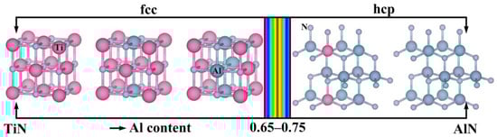
Figure 1.
Schematic diagram of the phase structure of TiAlN coating varying with the content of the Al element.
With technological advancements, tribological systems for friction-pair components demand enhanced performance. Consequently, PVD coatings require optimization to achieve higher adhesion strength, substrate load-bearing capacity, and coating–substrate compatibility. Recent studies demonstrate that novel coatings (e.g., multilayer and hybrid diffusion-PVD coatings) effectively improve these properties, significantly enhancing reliability and service life [26,27]. The significant disparity in physical properties between PVD hard coatings and substrates induces stress concentration at the interface, which may trigger coating delamination failure under mechanical loading [28]. The plasma nitriding-PVD hybrid technique addresses this issue by establishing a gradient transition layer on the substrate surface (comprising a high-hardness compound layer and a graded diffusion layer), effectively mitigating the stress distribution mismatch at the coating–substrate interface and substantially enhancing the load-bearing capacity of the coating system [29,30,31]. Niu et al. [32] fabricated TiAlN coatings via cathodic arc evaporation on ion-nitrided Ti6Al4V substrates. Their analysis demonstrated that nitrogen content modulation facilitated the formation of a graded transition layer between the compound layer and TiAlN coating. XRD characterization revealed a pronounced (200) crystallographic orientation in both the PN/TiAlN coating and TiN phase within the PN substrate. This coherent orientation relationship, combined with the graded transition layer, significantly enhanced the interfacial bonding integrity of the coating system. Deng et al. [33] conducted systematic investigations through Vickers hardness indentation testing to characterize the load-bearing capacity and interfacial bonding strength of coatings. Experimental results demonstrated that the PN/AlTiN composite coating achieved a bonding strength classification of HF 1, whereas the monolithic AlTiN coating exhibited significantly lower bonding strength, ranging between HF 3 and 4. Chen et al. [28] fabricated AlCrN coatings on SKD11 steel substrates following nitrocarburizing pretreatment, which exhibited a hardness of up to 43 GPa. Comparative analysis revealed that the nitrocarburizing pretreatment served as a critical factor in enhancing both coating hardness and load-bearing capacity, thereby constituting an effective approach to improve mechanical properties and wear resistance of the coatings.
In the framework of this study, TiAlN coatings were deposited via magnetron sputtering technology on nitrocarburized substrates, with a focused examination of N2 flow rate effects and nitrocarburized interlayer contributions to the mechanical/tribological performance of PNC/TiAlN composite systems. By implementing graded transition layers and optimizing reactive gas parameters, this work addresses critical knowledge gaps in designing robust TiAlN coatings for aerospace components under extreme tribological stresses. The systematic characterization establishes fundamental insights for optimizing wear-resistant TiAlN coatings through strategic PVD parameter engineering.
2. Materials and Methods
2.1. Specimen Preparation
The initial material was 300M high-strength alloy steel (40CrNi2Si2MoVA), the chemical composition of which is listed in Table 1 [1,2]. The workpieces were cut into 6 mm × 18 mm × 18 mm by the WEDM-CNC device. Before plasma nitrocarburizing and hard coating deposition, all workpieces were grounded using 1200-grit sandpaper, polished with 2.5 μm diamond grinding paste, and ultrasonically cleaned in ethanol.

Table 1.
The chemical composition of 300M steel (wt.%).
2.2. Modified Coatings Preparation
Using RF magnetron sputtering equipment, TiAlN coatings were applied to both 300M steel substrates and nitrocarburized specimens. A Ti0.5Al0.5 target, measuring 100 mm in diameter and 5 mm in thickness and boasting 99.99% purity, was positioned on the magnetron. The separation between the target and the samples was set at 25 mm. Before deposition, the vacuum chamber’s background pressure was reduced to 5.0 × 10⁻⁴ Pa, while the sputtering gas pressure was kept constant at 0.6 Pa. The process parameters for TiAlN coating preparation are as follows: sputtering power of 280 W and holding time for 3.5 h. In order to focus on studying the influence of the inflow amount of the reactive gas N2 on the TiAlN hard coating and the comprehensive performance of the prepared TiAlN coating, coupled with the nitrocarburized sample, three N2 inflow amounts are set for comparison, as specifically shown in Table 2.
Table 2.
The N2 flow rate of different TiAlN samples.
2.3. Characterization of Coatings
The microstructure morphologies and compositions of the as-prepared composite coatings were analyzed using field emission scanning electron microscopy (SEM, TESCAN-LYRA3, TESCAN ORSAY HOLDING a.s., Brno, Czech Republic) equipped with energy dispersive spectroscopy (EDS, XFlash® 6|60, Bruker Nano GmbH, Berlin, Germany). Surface roughness was evaluated through contact-mode atomic force microscopy (AFM, NTEGRA PRIMA, NT-MDT Spectrum Instruments, Moscow, Russia). Phase identification of the TiAlN coatings was performed via X-ray diffraction (XRD, Bruker D8 ADVANCE, Bruker AXS GmbH, Karlsruhe, Germany) with Cu Kα radiation, covering a range of 20°–90°, while grazing incidence XRD at 1° was specifically employed to determine the crystallographic phases of the TiAlN coatings. Mechanical properties were assessed through nanoindentation testing (Nanoindenter G200, Agilent Technologies Inc., Santa Clara, USA) with an indentation load of 80 mN. The continuous stiffness measurement (CSM) method utilized a Berkovich diamond to penetrate the TiAlN coating, deriving hardness and modulus of elasticity based on penetration depth, with a maximum indentation depth of tmax = 1000 nm. Adhesion, carrying capacity, and toughness were evaluated using Hardness Rockwell C indentations at a load of 1439 N, and the resulting indentation profiles were examined using a high-precision 3D profiler (3D Optical Profilometer, CONTOUR GT-K, Bruker Nano GmbH, Berlin, Germany).
2.4. Wear Tests
The PNC/TiAlN composite coatings studied in this project are primarily applied under heavy load conditions. According to Hertz’s analysis, different coatings can produce different contact pressures even during the friction and wear process under the same load, with the specific calculation formula as follows [34,35]:
where a is the Hertz contact radius, W is the normal applied load, R is the radius of the abrasive ball, and E* is the effective elastic modulus. The value of E* can be calculated using Formula (2) as follows:
In the equation, vball and vfilms represent the Poisson’s ratios of the abrasive ball and the coating material, respectively, while Eball and Efilms denote the elastic modulus of the abrasive ball and the coating material, respectively. Finally, the contact pressure P0 can be derived from Equation (3) as follows:
Through the analysis of the Hertzian contact theory, it is evident that the applied load significantly influences the friction and wear processes. Moreover, variations in the elastic modulus of different coatings result in distinct contact pressures, thereby leading to diverse wear mechanisms. In this study, a systematic investigation was conducted to examine the friction and wear behaviors of TiAlN and PNC/TiAlN coatings prepared under varying N2 flow rates and subjected to different loading conditions. The tribological characterization was carried out on a ball-disc-tester (HT-500, Lanzhou Institute of Chemical and Physics, Lanzhou, China). The experimental setup employed a ZrO2 ball with a diameter of 5.0 mm as the friction pair, the friction radius was 2 mm, with a rotating speed of 560 rpm, a test duration of 15 min, and ambient temperature conditions. Drawing on the prior research experience of our group and calculations based on the aforementioned theoretical framework, the wear tests were performed under two distinct loading conditions: 3.3 N (light load) and 7.3 N (heavy load). To further explore the wear mechanism, a high-precision 3D profiler (3D Optical Profilometer, CONTOUR GT-K, Bruker Nano GmbH, Berlin, Germany) was used to observe the depth of wear scars. The wear volumes V and specific wear rates K of samples were calculated on the basis of the following formula [36,37].
The parameter h represents the depth of the wear track, r is the rotating radius, b is the width of the wear track, P is the applied normal load, and S is the sliding distance.
3. Results and Discussion
3.1. Microstructure and Phases
Figure 2 presents the SEM morphology and EDS analysis results of the surface of No. (1–6) TiAlN and PNC/TiAlN samples prepared at N2 flow rates of 30 sccm, 90 sccm, and 150 sccm. The low-magnification SEM images reveal clear differences in surface morphologies between TiAlN and PNC/TiAlN samples. The TiAlN samples exhibit a uniform and dense surface without noticeable pores, whereas the TiAlN coatings in the PNC/TiAlN samples are grown in situ on the protruding structures of the substrate. Combined with the etching effect of the plasma, the TiAlN coating on the PNC/TiAlN sample also displays a protruding morphology, with localized fine voids present. Additionally, with an increasing N2 flow rate, agglomerated particles gradually form on the sample surface, and this phenomenon intensifies significantly at 150 sccm. As reported in previous studies [21,22], these agglomerated particles enhance the adsorption of background gases during the condensation process, thereby promoting a higher nitrogen ion incorporation ratio. High-magnification SEM observations (×30,000) reveal that both TiAlN and PNC/TiAlN coatings exhibit a characteristic island growth mode, with statistically consistent particle dimensions under identical deposition parameters. The particle dimensions increase with the N2 flow rate, accompanied by increasingly distinct intergranular boundaries, as demonstrated by image analysis in Figure 2(a1,b1,e1,h1). During the preparation process, the reaction pressure was maintained constant, while the gradual increase in the N2 flow rate resulted in a reduction of argon concentration within the chamber. This depletion directly suppressed the sputtering yield of alloy elements, thereby reducing the nucleation density on the substrate surface. Consequently, these synergistic effects promoted the coarsening and eventual agglomeration of surface particles.
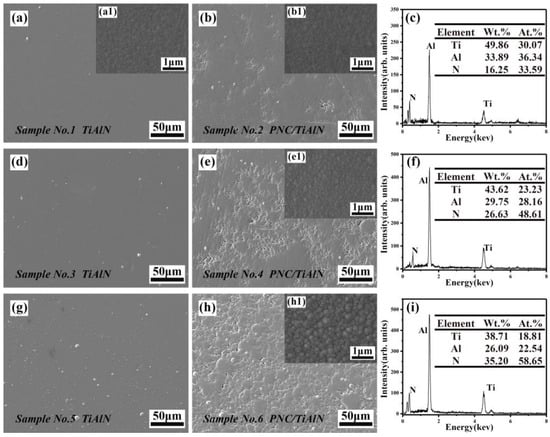
Figure 2.
The surface morphologies and EDS results of sample No. (1–6). (a,d,g) No. (1, 3, 5) TiAlN samples; (b,e,h) No. (2, 4, 6) PNC/TiAlN samples; (a1,b1,e1,h1) higher-magnification SEM at 30,000× for representative samples; (c,f,i) the corresponding EDS results of sample No. (1, 4, 6).
EDS elemental analysis was performed on TiAlN and PNC/TiAlN sample surfaces, as illustrated in Figure 2c,f,i. It was quantitatively observed that the elemental composition underwent substantial variation with increasing N2 flow rates. When the N2 flow rate was increased from 30 sccm to 150 sccm, the nitrogen content in the TiAlN coatings exhibited a significant enhancement from 33.59 at.% to 58.65 at.%. This nitrogen concentration gradient exerted profound impacts on the coating microstructure evolution, which consequently dictated the divergence in mechanical properties among specimens. The existing literature reveals that face-centered cubic (FCC) structured TiNx exhibits a broad compositional range (0.6 < x < 1.2), while AlNx demonstrates an analogous FCC configuration with similar non-stoichiometric characteristics [38,39]. Therefore, relying solely on EDS analysis cannot conclusively determine whether metallic Ti-Al phases (e.g., Ti3Al) or Ti2N phases exist in TiAlN coatings. A comprehensive phase identification should instead prioritize XRD-based phase characterization techniques, which provide crystallographic evidence for distinguishing atomic bonding types and lattice distortions. For TiAlN and PNC/TiAlN samples subjected to the same N2 flow rate, which were prepared in the same batch, their surface elemental compositions are essentially similar (minor errors in EDS measurements are considered acceptable here). Additionally, across various TiAlN samples, it is consistently observed that the Al atomic content is slightly higher than that of Ti. According to references [40,41], the sputtering yield of Al atoms is 1.05/500 eV (Ar+), whereas that of Ti atoms is only 0.51/500 eV (Ar+). Given that the Ti-Al alloy target used in this experiment has a composition of Ti0.5Al0.5, the Al content is expected to be marginally higher than that of Ti.
Figure 3 presents the AFM-3D topographies of TiAlN and PNC/TiAlN coatings deposited under varying N2 flow rates, with a scanning area of 5 μm × 5 μm. Notably, as the N2 flow rate increased, the average surface roughness of the TiAlN samples increased from 5.50 nm to 7.89 nm, whereas that of PNC/TiAlN coatings exhibited a more pronounced increase from 19.10 nm to 28.10 nm. This roughness evolution aligns quantitatively with the SEM surface morphology observations presented earlier.
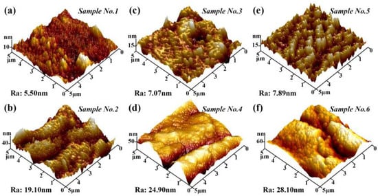
Figure 3.
No. (1–6) samples surface AFM 3D topography. (a,c,e) No. (1, 3, 5) TiAlN samples; (b,d,f) No. (2, 4, 6) PNC/TiAlN samples.
Figure 4 depicts the cross-sectional morphologies and the corresponding EDS line-scan spectra of samples No. (1–6) TiAlN and PNC/TiAlN under different N2 flow rates. To facilitate the distinction between the TiAlN and PNC/TiAlN samples, the latter were etched using 4% nitric acid alcohol solution. As shown in the figure, the TiAlN sample consists solely of a TiAlN coating and a 300M steel substrate, whereas the PNC/TiAlN sample is composed of a TiAlN coating, a nitrocarburized layer, and the substrate. The nitrocarburized layer further includes a compound layer and an internal diffusion layer, thereby forming a continuous hardness gradient from the surface to the interior of the substrate, which synergistically enhances interfacial adhesion and wear resistance through optimized phase distribution and stress gradient mitigation. Upon closer examination, it is observed that the boundary between the coating and the substrate in the TiAlN sample is remarkably straight and well-defined. In contrast, the interface between the TiAlN coating and the compound layer appears slightly blurred in some regions. This phenomenon can be attributed to the surface roughness of the nitrocarburized sample, as previously mentioned, which results in an uneven boundary between the TiAlN coating grown in situ on the surface and the compound layer. Additionally, the presence of fine voids caused by plasma etching leads to a “pinning”-like effect in localized areas of the TiAlN coating. Previous studies have demonstrated that moderately increasing the surface roughness of substrates significantly enhances the interfacial adhesion strength of hard coatings. Notably, the surface micro-voids observed in PNC/TiAlN specimens were absent in cross-sectional SEM observations, indicating that these micro-defects are superficial rather than penetrating the entire coating architecture.
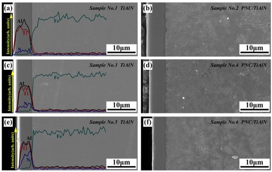
Figure 4.
The cross-sectional SEM images of samples No. (1–6). (a,c,e) No. (1, 3, 5) TiAlN samples and corresponding EDS line scan spectra; (b,d,f) No. (2, 4, 6) PNC/TiAlN samples.
As demonstrated in Figure 4, TiAlN and PNC/TiAlN samples fabricated in the same batch exhibit identical coating thicknesses under equivalent N2 flow rates. Systematic analysis reveals a monotonic thickness reduction (from 6.8 μm at 30 sccm to 4.6 μm at 150 sccm) with increasing N2 flux, accompanied by EDS spectral intensity variations indicating nitrogen enrichment in the coating matrix. This stoichiometric evolution aligns with surface EDS mapping, confirming nitrogen-incorporation-dominated growth kinetics. Deposition rate quantification (Figure 5) further demonstrates a decline across the tested N2 flow range, attributable to sputtering yield suppression under higher nitrogen partial pressures. The observed reduction in deposition rate is mechanistically attributed to three interdependent phenomena: (1) Ar+ ion depletion effect: under constant chamber pressure, progressive increases in N2 flux induce Ar+ concentration decay, directly impairing sputtering efficiency as per modified Berg–Sacher mode; (2) collision-induced scattering loss: excess N2 amplifies gas-phase collisions, diverting energetic particles from substrate-directed trajectories, thereby diminishing net effective deposition flux; (3) reactive target poisoning: accumulated N2 promotes rapid TiN and AlN phases formation on the target, establishing insulating ceramic layers that suppress sputtering yields.
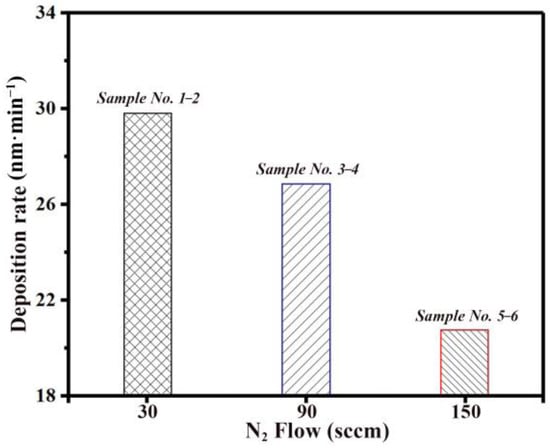
Figure 5.
The distribution of the deposition rate of TiAlN coating varies with the N2 flow rate.
Figure 6 presents the XRD patterns of TiAlN coatings deposited under varying N2 flow rates. Based on complementary surface and cross-sectional EDS analyses, the PNC/TiAlN specimen fabricated with a 90 sccm N2 flow rate was selected as the reference system. XRD analysis reveals that all TiAlN coatings are exclusively composed of FCC (Ti, Al)N solid-solution phases, exhibiting characteristic (200), (220), and (222) diffraction peaks at 2θ = 35.8°, 41.7°, and 60.3°, respectively. No detectable signatures of Ti-Al intermetallic compounds (e.g., Ti3Al) or sub-stoichiometric Ti2N phases were observed within the detection limits of conventional XRD instrumentation. The (Ti, Al)N diffraction peaks show negligible angular shifts with N2 flux escalation, and no detectable hcp-AlN signatures were observed, particularly the characteristic (100) peak at 2θ = 33.2° (PDF#25-1495), confirming the effective moderation of Al content during the preparation process. Notably, the PNC/TiAlN coating system displays two distinct Fe4N phase diffraction signatures at 2θ = 43.6° (111) and 50.8° (200). Cross-referencing with the PDF database reveals that the diffraction angles of the AlN phase (PDF#: 25-1495) exhibit significant overlap with those of the α-Fe phase (PDF#: 85-1410). Grazing-incidence XRD analysis of the TiAlN coating suggests possible α-Fe diffraction features, though these signals may be obscured by dominant (Ti, Al)N peaks. Crucially, the grazing-incidence XRD patterns provide definitive evidence that the observed diffraction features originate from the (Ti, Al)N solid solution phase, not the substrate’s α-Fe phase.
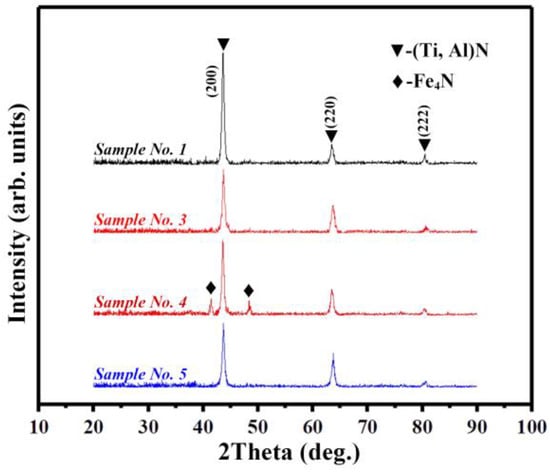
Figure 6.
XRD patterns of No. (1, 3, 5) TiAlN samples and No. 4 PNC/TiAlN sample.
3.2. Mechanical Properties
Figure 7 presents nanoindentation profiles of No. (1–6) TiAlN and PNC/TiAlN coatings deposited under varying N2 flow rates. As evidenced by panel (a), the load–displacement curves of TiAlN and PNC/TiAlN coatings fabricated at identical N2 flow rates exhibit remarkable similarity, demonstrating comparable maximum penetration depths and residual indentation depths under equivalent loading conditions. This consistency in indentation response indicates that specimens from the same deposition batch possess nearly identical mechanical properties, including hardness and elastic modulus. Comparative analysis reveals that the PNC/TiAlN specimen exhibits marginally higher hardness than its TiAlN counterpart. This enhancement is attributed to the nitrocarburizing pretreatment, which generates a hardened subsurface layer through interstitial solid solution strengthening. The modified substrate–coating interface effectively suppresses stress concentration during indentation, thus endowing the outer TiAlN coating with superior resistance to plastic deformation. To further investigate the hardness variation of the TiAlN coatings along the depth direction, we conducted depth-dependent hardness measurements on samples No. (3, 4) using the continuous stiffness method, as illustrated in Figure 7b. Both coatings exhibited nearly identical initial hardness values within the shallow penetration regime (<80 nm). However, the PNC/TiAlN system demonstrated superior hardness retention compared to conventional TiAlN in the 80–500 nm depth range, which is primarily attributed to the presence of a coherent compound layer at the coating–substrate interface.
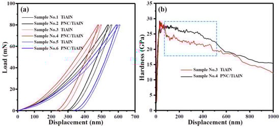
Figure 7.
(a) Load-displacement curves for samples No. (1–6) TiAlN and PNC/TiAlN; (b) hardness-displacement curves for samples No. 3 TiAlN and No. 4 PNC/TiAlN.
The primary mechanical parameters of specimens No. (1–6) prepared under varying N2 flow rates are summarized in Table 3. Under identical loading conditions, specimens No. 2, No. 4, and No. 6 exhibited distinct deformation responses, with maximum penetration depths of 542.2 nm, 482.7 nm, and 595.3 nm, respectively, and corresponding residual indentation depths of 290.1 nm, 227.9 nm, and 333.7 nm. This pronounced variation in mechanical behavior directly correlates with N2 flow rate-induced microstructural modifications, which synergistically enhance dislocation pinning efficacy and strain accommodation capabilities. Comparative analysis reveals significant hardness discrepancies governed by N2 flow rate optimization: the specimen prepared at 30 sccm N2 flux (No. 2) demonstrates substantially lower hardness (H = 23.77 ± 1.1 GPa) compared to the 90 sccm counterpart (No. 4, H = 27.13 ± 0.9 GPa), attributed to insufficient nitride formation. This phase deficiency results in compromised solid solution strengthening efficacy and reduced lattice distortion effects. As for sample No. 6 prepared at an N2 flow rate of 150 sccm, although a higher amount of nitrides is formed in the coating, the excessive N content leads to an inhomogeneous phase composition of (Ti, Al)Nx. Additionally, the relatively thinner thickness of this coating contributes to its lowest hardness (H = 19.14 ± 1.4 GPa) among the samples. Generally, the H/E and H3/(E)2 ratios, widely recognized as critical indices for evaluating wear resistance in tribological coatings, demonstrate a strong positive correlation with hardness and plastic deformation resistance. Comparative analysis reveals that the No. 4 PNC/TiAlN specimen exhibits superior mechanical performance, achieving an average nanoindentation hardness of 27.13 ± 1.1 GPa.
Table 3.
The corresponding mechanical property parameters of sample No. (1–6) TiAlN and PNC/TiAlN.
A comprehensive evaluation of coating fracture toughness and load-bearing capacity was conducted through standardized spherical indentation testing (ASTM E10, WC-Co indenter Ø1.588 mm) under 1439 N constant load (10 s dwell time), with post-indentation crack propagation patterns and coating failure modes analyzed via SEM. Figure 8 presents the systematic comparison of indentation morphologies across specimens No. (1–6) deposited under varying N2 flow rates (30–150 sccm), where subfigures (a,c,e) correspond to conventional TiAlN coatings, while Figure 8b,d,f represent the PNC/TiAlN variants, revealing fundamentally distinct mechanical responses between the two systems. The TiAlN coating specimens exhibited pronounced radial cracking patterns along the indentation periphery under high-load spherical indentation testing, attributed to the substantial hardness differential between the TiAlN coating and the 300M steel substrate, coupled with inadequate interfacial adhesion. This mismatch of mechanical properties will result in great interfacial shear stress, which exacerbates coating–substrate delamination. At a N2 flow rate of 30 sccm, severe warping of the coating around the indentation periphery was observed, accompanied by partial delamination at the edges, likely attributed to the inhomogeneous distribution of the (Ti, Al)Nx phase. At 90 sccm, significant warping was also observed around the indentation edges, but the coating remained relatively intact without large-scale delamination. This indicates that the internal connectivity of the TiAlN coating is enhanced when the (Ti+Al)/N ratio approaches 1:1, leading to a more uniform phase composition. In contrast, at 150 sccm, extensive delamination occurred around the indentation periphery, likely due to the significant difference in elastic modulus between the TiAlN coating and the 300M steel substrate, resulting in differential deformation behaviors under applied load and stress distribution. When the stress within the coating exceeded its fracture strength, catastrophic failure occurred, indicating inferior quality of the TiAlN coating under these conditions.
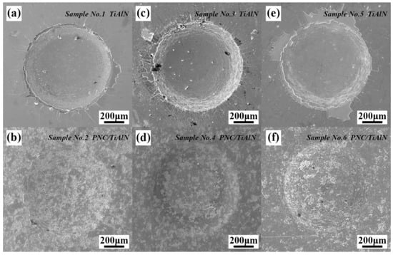
Figure 8.
The Rockwell C-Brale indentation SEM surface morphologies of samples No. (1–6) TiAlN and PNC/TiAlN. (a,c,e) No. (1, 3, 5) TiAlN samples; (b,d,f) No. (2, 4, 6) PNC/TiAlN samples.
Spherical indentation analysis of PNC/TiAlN nanocomposite coatings revealed fundamentally distinct fracture behaviors compared to conventional TiAlN systems. Across the full N2 flux range, the indentation morphologies were relatively similar. Systematic observations revealed the presence of multiple circular cracks within the indentation zones, while radial crack propagation or coating delamination were notably absent in the surrounding peripheral regions. This remarkable mechanical stability demonstrates the effectiveness of the PNC substrate in developing crack-resistant hard coatings. The compound layer formed through plasma nitrocarburization exhibits elevated hardness, thereby providing robust mechanical support to the TiAlN hard coating. During indentation testing, as the load is applied, the surface TiAlN hard coating sequentially transfers the imposed stress to the compound layer and the underlying diffusion layer. This mechanism facilitates the uniform distribution of stress within the substrate, effectively mitigating localized stress concentrations. Furthermore, the protruding topography of the compound layer induces a conformal convex morphology in the TiAlN hard coating, which mechanically suppresses localized crack propagation through interfacial stress redistribution. Consequently, the PNC/TiAlN coating system exhibits superior interfacial adhesion strength and enhanced coating toughness due to this synergistic geometric–mechanical coupling effect.
To qualitatively evaluate the coating’s load-bearing capacity, white-light interferometry was employed to conduct three-dimensional topographical scanning of indentation profiles for both TiAlN and PNC/TiAlN specimens, as systematically illustrated in Figure 9. This comparative analysis specifically focused on representative samples No. (1, 3, 5, 4) to elucidate critical differences in deformation characteristics between the coating systems. As illustrated in Figure 9a–c, the indentation depths of specimens No. 1, 3, and 5 exhibit remarkable consistency, revealing a substrate-dominated deformation mechanism under heavy-load conditions. The thickness of the coating is insufficient to manifest its intrinsic mechanical influence, with the substrate’s bulk properties governing the overall response. In contrast, Figure 9d reveals the enhanced load-bearing capability of the PNC/TiAlN system, where both indentation depth and width are significantly reduced compared to conventional TiAlN coatings, particularly with a notable reduction in depth of 30 μm. This highlights the enhanced mechanical performance and load-bearing capacity as well as adhesion properties of the PNC/TiAlN coating system.
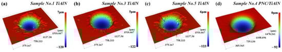
Figure 9.
Three-dimensional topography of the Rockwell C-Brale indentation test. (a–c) No. (1, 3, 5) TiAlN samples; (d) No. 4 PNC/TiAlN sample.
3.3. Tribological Properties
The friction coefficient curve serves as a critical diagnostic parameter for reconstructing wear evolution processes. In accordance with fundamental tribological principles, systematic analysis of these curves enables identification of material-specific wear mechanisms and quantitative evaluation of wear resistance. Consequently, a comparative wear performance analysis was conducted on No. (1–6) TiAlN and PNC/TiAlN coatings fabricated under varying N2 flow rates. Figure 10 presents the friction coefficient curves of No. (1–6) TiAlN and PNC/TiAlN coatings under a 3.3 N applied load. As evidenced in panels (a–c), the TiAlN coatings exhibit severe oscillatory behavior in their friction coefficient profiles across all tested N2 flow rates. This phenomenon is attributed to intermittent stick-slip phenomena at the ball–coating interface under light-load conditions, which results in rapid wear progression and significant localized delamination. In contrast, the PNC/TiAlN specimens exhibit gradual breaking during wear testing due to the protrusion architecture of the nitrocarburized substrate layer, effectively mitigating large-scale brittle spallation and maintaining stable friction coefficient evolution. However, their inherent surface roughness leads to comparatively elevated friction coefficients. As shown in panel (d), both TiAlN and PNC/TiAlN coatings demonstrate a positive correlation between average friction coefficients and N2 flow rates, a phenomenon predominantly attributed to synergistic effects of compositional variations and surface roughness characteristics at higher gas flux levels.
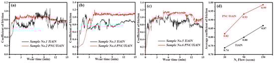
Figure 10.
The friction coefficient curves of samples No. (1–6) TiAlN and PNC/TiAlN at the load of 3.3 N. (a) Samples No. (1, 2); (b) samples No. (3, 4); (c) samples No. (5, 6); (d) average friction coefficient of samples No. (1–6).
Figure 11 compares the wear scar morphology of No. (1, 2) TiAlN and PNC/TiAlN coatings under the 3.3 N load with N2 flow rate fixed at 30 sccm. As revealed in Figure 11a, the wear track of the TiAlN coating exhibits extensive wear debris accumulation, accompanied by localized flattened zones observed in the central contact area. Figure 11b further demonstrates that the deeper regions outside these flattened areas are predominantly characterized by lamellar structures with pronounced delamination features, indicative of severe fatigue-induced damage under cyclic stress. Figure 11c presents the wear track morphology of the PNC/TiAlN coating, revealing a marginally reduced track width compared to its TiAlN counterpart. While similar flattening and fatigue-induced damage patterns are observed within the wear scar, the PNC/TiAlN system demonstrates an edge morphology smooth, devoid of the pronounced edge delamination or warping phenomenon in Figure 11a. High-magnification analysis reveals that the pervasive presence of finely dispersed wear debris adhered to the surface, with the wear track regions predominantly exhibiting lamellar morphological features (panel d). This observation suggests that the comparable wear track dimensions between the two coatings stem from their analogous mechanical properties in the TiAlN-dominated regimes. Notably, post-coating failure, the exposed high-hardness compound layer and its embedded carbide phases effectively mitigate progressive substrate degradation through load-bearing reinforcement and crack deflection mechanisms, thereby conferring enhanced wear resistance to the composite system.
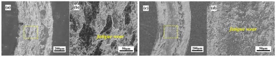
Figure 11.
The wear scar morphologies of No. (1, 2) TiAlN and PNC/TiAlN coatings at N2 flow rate of 30 sccm under 3.3 N loading condition. (a) Sample No. 1 TiAlN; (b) magnified SEM image at the yellow box region of panel (a); (c) sample No. 2 PNC/TiAlN; (d) magnified SEM image at the yellow box region of panel (c).
Figure 12 compares the wear scar morphology of No. (3, 4) TiAlN and PNC/TiAlN coatings under an elevated N2 flow rate of 90 sccm, revealing an evident reduction in scar width and wear depth compared to lower N2 flow conditions. The increase in N2 flow rate promotes a more uniform distribution of TiN and AlN phases within the coating, thereby enhancing its mechanical properties. Figure 12a displays the low-magnification wear scar morphology of the TiAlN coating. The scar region exhibits extensive flattened zones accompanied by fine wear debris distributed across the entire contact area. The analysis suggests that, under light-load conditions, stick-slip phenomena during friction induce inhomogeneous stress distribution across the coating surface. This mechanical instability leads to localized delamination of the coating in certain areas, while residual TiAlN fragments remain embedded within the scar. These residual fragments undergo progressive consumption or further fragmentation into debris under cyclic frictional loading. Furthermore, substantial remnants of the TiAlN coating were observed within the inner regions of the wear scar, while extensive brittle fracture phenomena were evident along the outer edges. This phenomenon can be attributed to the significant disparity in elastic modulus between the TiAlN coating and the substrate, coupled with the relatively low bonding strength at the coating–substrate interface, which collectively contribute to the heightened brittleness of the coating. During the wear process, the inner regions of the wear scar were subjected to compressive forces exerted by the grinding ball, whereas the outer regions experienced tensile stresses, leading to varying degrees of fracture. Figure 12b presents an enlarged view of localized areas, where numerous residual coating fragments are interconnected, thereby confirming their identity as remnants of the TiAlN coating. Figure 12c exhibits the wear scar morphology of the PNC/TiAlN coating. Notably, the outer periphery of the scar demonstrates an absence of pronounced spallation, while the inner periphery retains locally continuous residual TiAlN coating layers. This phenomenon can be attributed to the reciprocating compressive action of the grinding ball induces plastic deformation and localized densification of the coating. Figure 12d reveals the underlying compound layer morphology following TiAlN coating failure, characterized by protuberant surface architecture. This structural configuration demonstrates dual tribological enhancement mechanisms: (1) the increased specific surface area relative to the 300M steel substrate enhances particle adsorption capacity during coating deposition, thereby optimizing interfacial cohesion and wear resistance; (2) the recessed voids within the protrusions can accommodate and store wear debris, thereby mitigating the occurrence of abrasive wear.
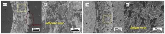
Figure 12.
The wear scar morphologies of No. (3, 4) TiAlN and PNC/TiAlN coatings at a N2 flow rate of 90 sccm under 3.3 N loading conditions. (a) Sample No. 3 TiAlN; (b) magnified SEM image at the yellow box region of panel (a); (c) sample No. 4 PNC/TiAlN; (d) magnified SEM image at the yellow box region of panel (c).
Figure 13 presents the wear track morphologies of TiAlN and PNC/TiAlN coatings for samples No. (5, 6) at an N2 flow rate of 150 sccm. Compared to the previous two sets of samples, it can be observed that the wear track width has significantly increased, and the amount of wear debris has substantially risen, with small areas of flattening occurring in some regions, as shown in Figure 13a,b. For the PNC/TiAlN coating, the wear scar width was comparable to that of the TiAlN specimen, accompanied by substantial debris accumulation and numerous flattened regions. The wear debris and flattened fragments within the entire scar area exhibited exceptional looseness. Under low-load conditions, the flattened regions demonstrated weak adhesion to the substrate surface, failing to establish robust bonding with the scar base, as illustrated in Figure 13c,d. For this group, the relatively inferior wear resistance originated primarily from the inherent limitations of lower coating hardness and insufficient thickness, which accelerated material removal and led to premature coating penetration. Consequently, both TiAlN specimens exhibited wear mechanisms predominantly characterized by cyclic fatigue-induced material delamination, with secondary contributions from abrasive wear and localized adhesive wear phenomena.
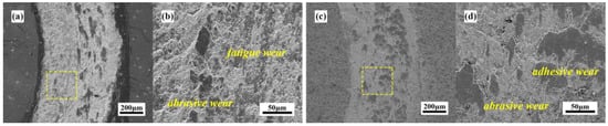
Figure 13.
The wear scar morphologies of No. (5, 6) TiAlN and PNC/TiAlN coatings at N2 flow rate of 150 sccm under 3.3 N loading condition. (a) Sample No. 5 TiAlN; (b) magnified SEM image at the yellow box region of panel (a); (c) sample No. 6 PNC/TiAlN; (d) magnified SEM image at the yellow box region of panel (c).
To quantitatively characterize the wear behavior of the specimen series, Figure 14 presents two-dimensional wear scar depth profiles for both TiAlN and PNC/TiAlN samples (No. 1–6) under a 3.3 N load. The corresponding specific wear rates were systematically calculated using the tribological model defined in Equations (4) and (5), enabling comparative analysis of coating degradation mechanisms. As evidenced by the cross-sectional profiles in Figure 14a,b, the TiAlN specimen exhibited a significantly larger wear scar cross-sectional area compared to its PNC/TiAlN counterpart under identical N2 flow rates, with the presence of relatively deep scratches, indicating the formation of deeper grooves during the wear process. As demonstrated in Figure 14c, the specific wear rates of specimens No. 1–6 reveal a notable reduction at the N2 flow rate of 90 sccm. Among these, the No. 4 PNC/TiAlN coating exhibited the lowest specific wear rate of 14.82 × 10⁻⁸ mm3·N−1·m−1, indicating superior wear resistance compared to other samples in the series.
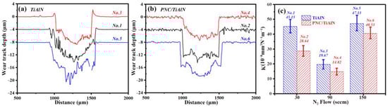
Figure 14.
Two-dimensional wear depth curves and specific wear rates of No. (1–6) TiAlN and PNC/TiAlN samples under 3.3 N loading conditions. (a) Two-dimensional wear mark depth curves of No. (1, 3, 5) TiAlN samples; (b) two-dimensional wear mark depth curves of No. (2, 4, 6) PNC/TiAlN samples; (c) the wear rates of No. (1–6) TiAlN and PNC/TiAlN samples.
Due to the differing wear mechanisms of materials under light and heavy load conditions, to contrast with the wear resistance and mechanisms discussed previously under light loads, and considering the heavy load application environment of PNC/TiAlN samples, dry friction tests were conducted under a load of 7.3 N. Similarly, an HT-500-type tribometer was employed with a sliding velocity of 7.03 m/min, a ZrO2 ball with a diameter of 5.0 mm as the counterface, and a test duration of 15 min, and the testing environment was at room temperature.
Figure 15 presents the coefficient of friction for TiAlN and PNC/TiAlN samples (No. (1–6)) under a 7.3 N load. As evident from the friction coefficient curves in Figure 15a–c, the TiAlN coating exhibited pronounced fluctuation amplitudes during sliding wear, which can be attributed to the occurrence of large-scale brittle spalling and micro-vibrations caused by abrasive wear. In contrast, the PNC/TiAlN coating exhibited significantly stabilized friction coefficient curves, which can be attributed to its enhanced fracture toughness that effectively confined coating damage within the wear track. Consequently, as evidenced in Figure 15d, the PNC/TiAlN coating demonstrated a markedly lower friction coefficient compared to the TiAlN counterpart under severe loading conditions of 7.3 N. Compared to the 3.3 N low-load testing condition, the friction coefficient exhibited a significant reduction under heavy-load 7.3 N conditions. This phenomenon can be attributed to the combined effects of reduced stick-slip phenomena between the tribological pair and increased actual contact area at the coating interface, both of which contributed to the effective reduction in frictional forces.
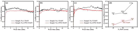
Figure 15.
The friction coefficient curves of the samples No. (1–6) TiAlN and PNC/TiAlN at the load of 7.3 N. (a) Samples No. (1, 2); (b) samples No. (3, 4); (c) samples No. (5, 6); (d) average friction coefficient of the samples No. (1–6).
Figure 16 illustrates the wear scar morphology of No. (1, 2) TiAlN and PNC/TiAlN coatings under a 7.3 N applied load. As shown in Figure 16a, the wear scar exhibited significant widening compared to the 3.3 N loading condition, accompanied by the formation of multiple lamellar tearing features and substantial debris accumulation across the scar surface. Figure 16b further revealed extensive crack propagation surrounding the lamellar tearing zones, with localized regions demonstrating characteristic adhesive wear patterns. Under high-load conditions, the effective contact area between the coating and the counterface ball increases. Once coating failure occurs, TiAlN-derived wear debris intensifies substrate abrasion, generating proliferated wear products that induce deep plowing grooves and material tearing within the substrate. This substantiates a wear regime dominated by abrasive wear and fatigue-induced delamination, with limited adhesive wear manifestations. Figure 16c illustrates the microscopic morphology of the PNC/TiAlN wear track, where the wear track width is slightly reduced compared to sample No. 1, with no evident plowing or deep scratches, and the amount of wear debris is significantly diminished. Furthermore, Figure 16d reveals localized regions retaining partially delaminated TiAlN coating fragments, indicating incomplete spallation during the testing. The analysis suggests that the PNC substrate provides robust support for the TiAlN coating, effectively reducing the plastic deformation of the coating during the wear process. Under heavy-load conditions, the bouncing phenomenon between the loading ball and the coating is also diminished, thereby delaying the coating’s failure. After the coating is damaged, some unevenly distributed TiAlN coating remnants remain on the wear scar surface. This phenomenon is likely attributed to the “pinning” effect induced by the protruding structures of the nitrocarburized layer, which enhances the local interfacial bonding strength. As a result, the residual coating continues to offer a certain degree of protection to the substrate. In summary, the wear mechanism of the PNC/TiAlN coating at this time is mainly fatigue wear, and its wear resistance is significantly improved compared to the TiAlN coating.
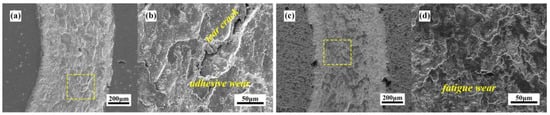
Figure 16.
The wear scar morphologies of No. (1, 2) TiAlN and PNC/TiAlN coatings at a N2 flow rate of 30 sccm under a 7.3 N loading condition. (a) Sample No. 1 TiAlN; (b) magnified SEM image at the yellow box region of panel (a); (c) sample No. 2 PNC/TiAlN; (d) magnified SEM image at the yellow box region of panel (c).
Figure 17a displays the wear scar morphology of the TiAlN coating deposited at a 90 sccm N2 flow rate. Compared with the specimen prepared at 30 sccm, both coatings demonstrated comparable wear severity, characterized by deeply penetrating plowing grooves and extensive debris accumulation. The No. 3 TiAlN specimen exhibited a slight reduction in wear scar width attributed to its enhanced coating hardness. However, under high-load conditions, intensified compressive stresses at the scar periphery from the counterbody induced localized brittle delamination. As distinctly observed in Figure 17b, substantial debris accumulation occurred at the trench base while bulk flattened zones formed across elevated regions. These tribological signatures collectively confirm abrasive wear as the dominant wear mechanism for the TiAlN coating under such loading regimes. As shown in Figure 17c, the wear scar morphology of the PNC/TiAlN coating exhibits substantial retention of the TiAlN layer, indicating its protective capacity. Furthermore, the serrated inner edges of the scar further indicated localized compressive spallation under high-load conditions, which occurred sporadically without developing into the extensive brittle delamination observed in sample No. 3. As shown in Figure 17d, the residual TiAlN coating within the wear scar demonstrated excellent interfacial adhesion to the nitrocarburized layer. Following localized delamination of the TiAlN coating, the exposed granular nitrocarburized sublayer still demonstrates a certain degree of protective efficacy. The analytical results demonstrate that the TiAlN coating fabricated at a 90 sccm N2 flow rate exhibited optimal compatibility in mechanical properties with the nitrogen–carbon co-diffusion layer, which contributed to enhanced interfacial bonding strength. Under heavy-load conditions, the TiAlN coating effectively transferred frictional stresses progressively through the compound layer, internal diffusion layer, and substrate, resulting in a more uniform stress distribution across the multilayer architecture. Consequently, the PNC/TiAlN coating experienced predominantly fatigue wear mechanisms with limited adhesive wear initiation under this load regime.
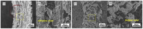
Figure 17.
The wear scar morphologies of No. (3, 4) TiAlN and PNC/TiAlN coatings at a N2 flow rate of 90 sccm under a 7.3 N loading condition. (a) Sample No. 3 TiAlN; (b) magnified SEM image at the yellow box region of panel (a); (c) sample No. 4 PNC/TiAlN; (d) magnified SEM image at the yellow box region of panel (c).
Figure 18 shows the wear track morphologies of No. (5, 6) TiAlN and PNC/TiAlN coatings at the N2 flow rate of 150 sccm. The diminished hardness and reduced thickness of the TiAlN coating resulted in a significant deterioration of its wear resistance, consequently leading to a pronounced increase in wear scar width under heavy-load conditions. Furthermore, the non-uniform load distribution from the grinding ball during the wear process likely contributed to the formation of multi-depth grooves on the left side of the scar, while the right side exhibited relatively uniform abrasive scratches characterized by planarized wear morphology. As observed in Figure 18b, the wear scar exhibited a bimodal debris distribution comprising both fine particulate debris and coarse bulk particles. These macroscopic particles originated from the tearing and subsequent compaction of the substrate material during cyclic tribological loading. Consequently, the predominant wear mechanism of the TiAlN coating under these conditions is identified as abrasive wear. Figure 18c illustrates the wear scar morphology of the PNC/TiAlN coating. Despite the comparable surface hardness between the two coatings and the mechanical support provided by the PNC substrate to the TiAlN layer, the combination of lower surface hardness and PNC substrate interaction failed to enhance wear resistance effectively. The observed reduction in wear scar width is attributed to the exposed nitrocarburized layer after coating failure, which exhibited superior tribological properties compared to the original coating system. As revealed in Figure 18d, the wear scar morphology exhibited a relatively smooth topography with localized debris accumulation yet showed no particulate structures analogous to those observed in sample No. 4. This absence of granular features suggests severe wear progression, where original particulate architectures were completely abraded into planar configurations.
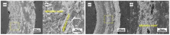
Figure 18.
The wear scar morphologies of No. (5, 6) TiAlN and PNC/TiAlN coatings at a N2 flow rate of 150 sccm under a 7.3 N loading condition. (a) Sample No. 5 TiAlN; (b) magnified SEM image at the yellow box region of panel (a); (c) sample No. 6 PNC/TiAlN; (d) magnified SEM image at the yellow box region of panel (c).
Figure 19 presents the two-dimensional wear scar depth profiles and specific wear rates of No. (1–6) TiAlN and PNC/TiAlN samples under the 7.3 N applied load. As shown in Figure 18a,b, the cross-sectional profiles of wear scars demonstrate comparable scar widths between samples No. (1, 3, 5) and No. (2, 4, 6), but distinct deep grooves were observed in the wear tracks of samples No. (1, 3, 5). Figure 19c delineates the specific wear rates of specimens No. 1–6 under the 7.3 N applied load. The TiAlN samples exhibited consistently higher specific wear rate values compared to their PNC/TiAlN counterparts, with the No. 4 specimen demonstrating the lowest specific wear rate of 25.23 × 10⁻⁸ mm3·N−1·m−1. Comparative analysis with the 3.3 N wear results revealed a pronounced increase in wear scar width under high-load conditions, while the corresponding depth increment exhibited a relatively smaller increase. This disparity in dimensional wear evolution directly contributed to the observed upward trend in specific wear rate at elevated loads. Consequently, the No. 4 PNC/TiAlN specimen demonstrated superior mechanical properties and wear resistance, confirming its enhanced suitability for heavy-load operational environments.
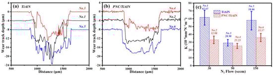
Figure 19.
Two-dimensional wear depth curves and specific wear rates of No. (1–6) TiAlN and PNC/TiAlN samples under 7.3 N loading conditions. (a) Two-dimensional wear mark depth curves of No. (1, 3, 5) TiAlN samples; (b) two-dimensional wear mark depth curves of No. (2, 4, 6) PNC/TiAlN samples; (c) the wear rates of No. (1–6) TiAlN and PNC/TiAlN samples.
4. Conclusions
This study elucidates the critical role of N2 flow rate modulation and nitrocarburized (PNC) interlayers in governing the microstructure, mechanical properties, and tribological performance of TiAlN coatings deposited on 300M steel substrates. The PNC/TiAlN composite coatings exhibited superior interfacial adhesion and load-bearing capacity compared to monolithic TiAlN coatings, primarily attributed to the graded hardness transition and optimized stress distribution at the coating–substrate interface. The nitrocarburizing pretreatment generated a functionally graded diffusion layer, which effectively mitigated the abrupt mechanical property mismatch between the hard TiAlN coating and the ductile substrate, thereby suppressing stress concentration and delamination tendencies, leading to the following conclusions:
Increasing N2 flow rates from 30 to 150 sccm significantly influenced elemental composition and phase evolution. EDS analysis confirmed a progressive enhancement in nitrogen content (33.59–58.65 at.%), correlating with microstructural coarsening and particle agglomeration due to reduced argon concentration and sputtering yield. XRD characterization suggested that higher N2 flow rates promoted phase stabilization of the face-centered cubic (FCC) TiAlN structure while suppressing metastable phases, which contributed to enhanced hardness (19.41–27.13 GPa) and elastic modulus (220 ± 9–267 ± 12 GPa) in PNC/TiAlN systems. The synergistic effect of nitrogen enrichment and PNC interlayers facilitated the formation of a coherent interfacial structure, as evidenced by the aligned (200) crystallographic orientation between the TiAlN coating and substrate phases.
Tribological performance improvements in PNC/TiAlN coatings stemmed from multiple mechanisms: (1) the graded hardness profile minimized plastic deformation under shear stress, (2) optimized stress distribution reduced crack initiation and propagation, and (3) nitrocarburized pretreatment enhanced resistance to abrasive wear. Notably, when the load conditions increased to 7.3 N, a relative reduction in the friction coefficient was observed. The composite coatings demonstrated superior wear resistance (specific wear rate: 25.23 × 10⁻⁸ mm3·N−1·m−1) compared to the monolithic TiAlN coatings. The PNC substrate provided substantial mechanical support to the residual coating, while the interfacial “pinning” effect between the two phases generated enhanced bonding strength at their interface. This synergistic interaction effectively mitigated plastic deformation of the coating during the wear process, demonstrating that the PNC/TiAlN composite exhibits superior suitability for heavy-load applications.
The findings establish a paradigm for designing robust TiAlN coating systems, emphasizing the necessity of coupling reactive gas modulation with substrate preconditioning to achieve balanced mechanical tribological performance. Future work should focus on optimizing the N2 flow to maximize interfacial coherence while mitigating particle agglomeration, particularly for aerospace components requiring extended service lifespans in extreme environments.
Author Contributions
Conceptualization, S.Z., Q.L. and Z.F.; methodology, S.Z., Q.L., Z.F. and X.T.; software, X.W., H.X., Q.S. and T.J.; validation, Q.L., Z.F. and X.W.; formal analysis, S.Z., Q.L., Z.F., X.T., X.W., H.X., Q.S., T.J. and H.W.; writing—original draft preparation, S.Z., Q.L., Z.F. and X.T.; writing—review and editing, S.Z., X.W., Q.S. and T.J.; supervision, H.W.; funding acquisition, S.Z., X.W., H.X. and Q.S. All authors have read and agreed to the published version of the manuscript.
Funding
This research received no external funding.
Data Availability Statement
Dataset available on request from the authors.
Acknowledgments
This work was supported by the Doctor of Suzhou University Scientific Research Foundation (2023BSK013, 2023BSK010, 2023BSK017, 2023BSK054).
Conflicts of Interest
Author Tianshi Jia was employed by Zhengtai Anneng Digital Energy (Zhejiang) Co., Ltd. The remaining authors declare that the research was conducted in the absence of any commercial or financial relationships that could be construed as a potential conflict of interest.
References
- Dang, J.Q.; Wang, C.G.; Wang, H.H.; An, Q.L.; Wei, J.; Gao, B.; Liu, Z.M.; Chen, M. Deformation behavior and microstructure evolution of 300M ultrahigh strength steel subjected to high strain rate: An analytical approach. J. Mater. Res. Technol. 2023, 25, 812–831. [Google Scholar] [CrossRef]
- Dong, Y.; Lan, X.Q.; Yang, S.Q.; Lu, J.X.; Yan, S.Y.; Wei, K.W.; Wang, Z.M. Effect of quenching and tempering treatments on microstructure and mechanical properties of 300M ultra-high strength steel fabricated by laser powder bed fusion. Mater. Charact. 2024, 212, 113935. [Google Scholar] [CrossRef]
- Xiong, Y.B.; Wen, D.X.; Zheng, Z.Z.; Sun, C.Y.; Xie, J.; Li, J.J. Effect of heat treatment on microstructure and mechanical properties of directed energy deposition-Arc 300M steel. Mater. Charact. 2023, 198, 112756. [Google Scholar] [CrossRef]
- Cong, J.H.; Wang, J.H.; Zhou, S.; Wang, L.; Hui, L. Correction: Impact of Ultrasonic Surface Rolling Processes on Microstructures and Fatigue Properties of 300M Steel Laser-Cladding-Repaired Components. J. Mater. Eng. Perform. 2025, 34, 1470. [Google Scholar] [CrossRef]
- Lepitre, P.; Merlet, L.M.; Doudard, C.; Dhondt, M.; Surand, M.; Calloch, S.S. Influence of shot-peening on the self-heating behavior and fatigue properties of 300M steel. Mech. Mater. 2024, 199, 105174. [Google Scholar] [CrossRef]
- Zhao, W.D.; Liu, D.X.; Hao, Z.Q.; Shi, H.L.; Zhang, H.; Sun, N.N.; Liu, H.; Tang, F.H.; Li, H.Y.; Liu, Q.; et al. Improvement of corrosion and wear resistances of 300M ultra high strength steel by low temperature cathode assisted plasma nitriding. Surf. Coat. Technol. 2024, 479, 130518. [Google Scholar] [CrossRef]
- Zhang, M.M.; Zhai, L.; Xue, Y.; Xu, Y.J.; Wu, W.J.; Jiang, Y.; Gong, J.M. Unusual intermediate layer precipitation in low-temperature salt bath nitrocarburized 316L austenitic stainless steel. Surf. Coat. Technol. 2024, 494, 131521. [Google Scholar] [CrossRef]
- Dou, H.C.; Zhang, Z.H.; Zhang, M.Y.; Zhou, Z.L.; Yi, X.N.; Wang, Z.W.; Jiang, M.Q.; He, Y.Y.; Li, Y. Tribological properties of the modified layers prepared on 38CrMoAl steel by plasma nitrocarburized and post-sulfurized method. Vacuum 2024, 228, 1134473. [Google Scholar] [CrossRef]
- Alves, U.C.; Ricci, V.P.; Mota, I.G.C.; Koga, G.Y.; Hassui, A.; Ventura, C.E. Mechanical and tribological characterization of TiAlN/TiN and TiSiN/AlTiN coating systems for cutting tools. J. Manuf. Process. 2025, 145, 522–535. [Google Scholar] [CrossRef]
- Chang, W.; Zhang, H.; Tian, C.; Xue, Y.; Liu, G. nfluence of La/Al Doping via Magnetron Sputtering on the Mechanical and Tribological Properties of TiN Coatings. Coatings 2025, 15, 284. [Google Scholar] [CrossRef]
- Zhang, M.M.; Li, R.Z.; Zhang, Y.Q.; Li, Y.F.; Niu, Y.S.; Xin, L.; Zhu, S.L.; Wang, F.H. Comparison of microstructure stability and oxidation resistance of Ti/TiN, Ti/TiAlN, and Cr/TiAlN multilayer coatings on TC4 titanium alloy under thermal cycling. J. Alloys Compd. 2025, 1019, 179310. [Google Scholar] [CrossRef]
- Zhao, J.F.; Liu, Z.Q. Influences of coating thickness on cutting temperature for dry hard turning Inconel 718 with PVD TiAlN coated carbide tools in initial tool wear stage. J. Manuf. Process. 2020, 56, 1155–1165. [Google Scholar] [CrossRef]
- Yang, X.; Lin, H.; Chen, Y.; He, Y.; Shen, Z. Effect of AlTiN Coating Structure on the Cutting Performance of Cemented Carbide PCB Microdrills. Coatings 2025, 15, 520. [Google Scholar] [CrossRef]
- Akhter, R.; Bendavid, A.; Munroe, P. Improving the wear resistance and scratch adhesion strength of TiAlN coatings via Al incorporation. Thin Solid Films 2025, 816, 140650. [Google Scholar] [CrossRef]
- Hemmati, A.; Paiva, J.; Veldhuis, S. Thermal stability and machining performance of arc evaporated Ti1−xAlxN hard PVD coatings with x = 0.5–0.73 ratios using an integrative approach. Materialia 2021, 17, 101132. [Google Scholar] [CrossRef]
- Hörling, A.; Hultman, L.; Odén, M.; Sjölén, J.; Karlsson, L. Thermal stability of arc evaporated high aluminum-content Ti1−xAlxN thin films. J. Vac. Sci. Technol. A 2002, 20, 1815–1823. [Google Scholar] [CrossRef]
- Mayrhofer, P.H.; Hörling, A.; Karlsson, L.; Sjölén, J.; Larsson, T.; Mitterer, C.; Hultman, L. Self-organized nanostructures in the Ti–Al–N system. Appl. Phys. Lett. 2003, 83, 2049–2051. [Google Scholar] [CrossRef]
- Santana, A.E.; Karimi, A.; Derflinger, V.H.; Schütze, A. The role of hcp-AlN on hardness behavior of TiAlN nanocomposite during annealing. Thin Solid Films 2004, 469, 339–344. [Google Scholar] [CrossRef]
- Chakrabarti, K.; Jeong, J.J.; Hwang, S.K.; Yoo, Y.C.; Lee, M.C. Effects of nitrogen flow rates on the growth morphology of TiAlN films prepared by an rf-reactive sputtering technique. Thin Solid Films 2002, 406, 159–163. [Google Scholar] [CrossRef]
- Jeong, J.J.; Hwang, K.S.; Lee, M.C. Nitrogen flow rate dependence of the growth morphology of TiAlN films deposited by reactive sputtering. Surf. Coat. Technol. 2002, 151–152, 82–85. [Google Scholar] [CrossRef]
- Bujak, J.; Walkowicz, J.; Kusiński, J. Influence of the nitrogen pressure on the structure and properties of (Ti,Al)N coatings deposited by cathodic vacuum arc PVD process. Surf. Coat. Technol. 2004, 180–181, 150–157. [Google Scholar] [CrossRef]
- Biro, D.; Barna, P.B.; Szekely, L.; Geszti, O.; Hattori, T.; Devenyi, A. Preparation of multilayered nanocrystalline thin films with composition-modulated interfaces. Nucl. Instrum. Methods Phys. Res. Sect. A Accel. Spectrometers Detect. Assoc. Equip. 2008, 590, 99–106. [Google Scholar] [CrossRef]
- Chen, L.; Moser, M.; Du, Y.; Mayrhofer, P.H. Compositional and structural evolution of sputtered Ti-Al-N. Thin Solid Films 2009, 517, 6635–6641. [Google Scholar] [CrossRef]
- Soni, R.; Sarin, V.K.; Rao, P.; Srinivasan, E.; Basu, S.N. Growth of AlN coating on Al-6061 alloy surface. Surf. Coat. Technol. 2023, 476, 130254. [Google Scholar] [CrossRef]
- Cheon, J.M.; Jung, I.H. Critical evaluation and thermodynamic modeling of the AlN-Al2O3 and the AlN-Al2O3-MgO systems and applications to AlN and MgAlON sintering process. J. Eur. Ceram. Soc. 2024, 45, 117168. [Google Scholar] [CrossRef]
- Paldey, S.; Deevi, S.C. Single layer and multilayer wear resistant coatings of (Ti, Al)N: A review. Mat. Sci. Eng. A-Struct. 2003, 342, 58–79. [Google Scholar] [CrossRef]
- Musil, J.; Hruby, H. Superhard nanocomposite Ti1-xAlxN films prepared by magnetron sputtering. Thin Solid Films 2000, 365, 104–109. [Google Scholar] [CrossRef]
- Chen, W.L.; Zheng, J.; Meng, X.N.; Kwon, S.; Zhang, S.H. Investigation on microstructures and mechanical properties of AlCrN coatings deposited on the surface of plasma nitrocarburized cool-work tool steels. Vacuum 2015, 121, 194–201. [Google Scholar] [CrossRef]
- Hawryluk, M.; Gronostajski, Z.; Widomski, P.; Kaszuba, M.; Ziemba, J.; Smolik, J. Influence of the application of a PN+Cr/CrN hybrid layer on the improvement of the lifetime of hot forging tools. J. Mater. Process. Technol. 2018, 258, 226–238. [Google Scholar] [CrossRef]
- Feng, X.G.; Hu, H.J.; Gui, B.H.; Guo, F.J.; Wang, K.L.; Zheng, Y.G.; Zhou, H. Corrosion behavior of W-DLC and DLC films deposited on plasma nitrided CF170 steel in H2SO4 solution. Vacuum 2022, 204, 111385. [Google Scholar] [CrossRef]
- Zuo, S.W.; Miao, Q.; Liang, W.P.; Xiao, F.N.; Liu, R.X.; Liu, Y.Y.; Ding, Z.; Yang, Z.G. A study on the mechanical performance and medium temperature tribological behavior of plasma nitrocarburizing/TiAlSiN/DLC composite coating. Surf. Interfaces 2021, 27, 101489. [Google Scholar] [CrossRef]
- Niu, R.L.; Li, J.L.; Wang, Y.X.; Chen, J.M.; Xue, Q.J. Structure and high temperature tribological behavior of TiAlN/nitride duplex treated coatings on Ti6Al4V. J. Surf. Coat. Technol. 2017, 309, 232–241. [Google Scholar] [CrossRef]
- Deng, Y.; Tan, C.L.; Wang, Y.; Chen, L.; Cai, P.P.; Kuang, T.C.; Lei, S.M.; Zhou, K.S. Effects of Tailored Nitriding Layers on Comprehensive Properties of Duplex Plasma-treated AlTiN coatings. Ceram. Int. 2017, 43, 8721–8729. [Google Scholar] [CrossRef]
- Huang, J.X.; Wan, S.H.; Wang, L.P.; Xue, Q.J. Tribological Properties of Si-Doped Graphite-Like Amorphous Carbon Film of PEEK Rubbing with Different Counterparts in SBF Medium. Tribol. Lett. 2015, 57, 10. [Google Scholar] [CrossRef]
- Timoshenko, S.P.; Goodier, J.N. Theory of Elasticity, 3rd ed.; McGraw-Hill Book Company: New York, NY, USA, 1970. [Google Scholar]
- Li, C.; Tang, Z.L.; Chai, Y.D.; Wei, S.Y.; Du, F.; Yang, L.; Zhou, Y.C. Critical parameters on sliding wear behavior in abradable sealing coatings. Wear 2025, 574–575, 206072. [Google Scholar] [CrossRef]
- Wu, J.X.; Wang, Z.; Yang, H.J.; Qiao, J.W. Sliding wear behavior and mechanism of Zr-based bulk metallic glasses and metallic glass matrix composites. Wear 2025, 658, 123520. [Google Scholar] [CrossRef]
- Yu, S.Y.; Zeng, Q.F.; Oganov, A.R.; Frapper, G.; Zhang, L.T. Phase stability, chemical bonding and mechanical properties of titanium nitrides: A first-principles study. Phys. Chem. Chem. Phys. 2014, 17, 11763. [Google Scholar] [CrossRef]
- Ling, L.; Song, B.; Cao, P.L. Theoretical study on structures of small nonstoichiometric AlN clusters. J. Mol. Struct. THEOCHEM 2005, 728, 215–223. [Google Scholar] [CrossRef]
- Fenker, M.; Eichenhofer, G.T.; Baeurer, D.; Gruenwald, J.; Oberberg, M.; Albrecht, J.; Kaßner, H. Pioneering work for the implementation of the inverted fireball technology for more effective PVD magnetron sputtering. Surf. Coat. Technol. 2025, 505, 132119. [Google Scholar] [CrossRef]
- Bermanschläger, S.C.; Hajas, B.I.; Wojcik, T.; Ntemou, E.; Primetzhofer, D.; Kolozsvari, S.; Bleicher, F.; Mayrhofer, P.H. Structure, chemistry, and mechanical properties of non-reactively sputtered Ti-Al-N. Mater. Des. 2025, 252, 113803. [Google Scholar] [CrossRef]
Disclaimer/Publisher’s Note: The statements, opinions and data contained in all publications are solely those of the individual author(s) and contributor(s) and not of MDPI and/or the editor(s). MDPI and/or the editor(s) disclaim responsibility for any injury to people or property resulting from any ideas, methods, instructions or products referred to in the content. |
© 2025 by the authors. Licensee MDPI, Basel, Switzerland. This article is an open access article distributed under the terms and conditions of the Creative Commons Attribution (CC BY) license (https://creativecommons.org/licenses/by/4.0/).