1. Introduction
Journal bearings are one of the key components of rotating machinery. They ensure the normal operation, smooth rotation, and long service life of various rotating equipment, such as industrial motors and aero engines. They are crucial for supporting the accurate position of the rotating shaft and maintaining its stable motion, thereby guaranteeing the normal operation of the entire system. However, under actual working conditions, journal bearings are often subjected to harsh environments. Friction, wear, and heat are the main factors that affect the performance of journal bearings. Wear can significantly reduce the efficiency of bearings [
1,
2], while the temperature–viscosity characteristic of lubricants has a marked impact on bearing lubrication [
3].
In response to the above challenges, the existing literature focuses on elucidating the influence of the surface roughness and geometric structure of journal bearings on its working performance. The research shows that the surface texture has beneficial effects on the bearing’s performance, such as lubrication, pressure distribution, and the LCC [
4]. Changing the shape, position, and geometric parameters of the surface texture directly affects the bearing’s performance. When the surface texture is optimized, the lubricating oil is evenly distributed, leading to improved lubrication, an increased LCC, reduced friction and heat generation, and minimized energy loss [
5,
6,
7,
8,
9,
10]. In 2017, Shinde et al. studied the effect of partial grooving on the performance of hydrodynamic bearings. They found that partial textures in the 90–180° range significantly improved the maximum oil film pressure and LCC while reducing the friction power loss and torque, and in the following year, they investigated the effect of deterministic micro-textures on the performance of hydrodynamic journal bearings using numerical analysis [
11,
12]. Manser (2019) studied the tribological characteristics of micro-textured surfaces under shaft misalignment and reported significant improvements in the LCC and energy efficiency [
13]. Sharma demonstrated that a V-shaped surface texture enhances the bearing performance under specific depth, area, and low shaft eccentricity ratio conditions [
14]. Mohammad Arif et al., in 2022, investigated the combined effects of slip boundary conditions and pseudoplastic lubricants on the tribological performance of hydrodynamic textured journal bearings [
15]. In 2024, Dass et al. used the Barus variable viscosity formula, ferrofluid as a magnetic lubricant, and the Finite Difference Method (FDM) to study the effects of variable viscosity, sinusoidal surface texturing, slip velocity, magnetic fluid, and couple-stress lubricants on journal bearing characteristics [
16]. Marey et al. investigated the journal bearing performance under slow speeds and varying loads through a novel CFD model and experimental validation [
17].
In recent years, more novel and sophisticated optimization strategies have been employed in the design of journal bearings, thereby enhancing their efficiency and reliability. In 2020, Bhasker et al. used a Taguchi-fuzzy optimization approach to analyze the hydrodynamic performance of phosphorous bronze journal bearings under various operating conditions [
18]. Codrignani et al. (2020) used the adjoint optimization method to optimize surface textures in hydrodynamic lubrication with cavitating flows [
19]. In 2022, DJ Ramos et al. combined particle swarm optimization (PSO) with gradient-based optimization to optimize texture depth, ultimately achieving an increased LCC, reduced fluid shear, and minimized lubricant temperature rise [
20]. Smolík et al. (2023) used theoretical and experimental methods to investigate how mechanical indentation textures affect the stability of lightly loaded journal bearings and concluded that the computational mesh density significantly impacts the numerical results and that textures can enhance stability and reduce vibrations under certain conditions [
21]. More recently, in 2024, Fabrizio Antonio Stefani et al. conducted a study on the coupling of torsional and lateral vibrations in drive lines supported by hydrodynamic journal bearings using experimental and numerical methods [
22]. In the same year, Profito et al. integrated experimental and numerical simulation approaches to explore the impact of laser-etched textures on the tribological performance of journal bearings [
23].
Previous research has paid more attention to the impact of parameters on the bearing performance, but overlooked exploring a flexible and universal method to optimize the geometry of the journal bearing, despite its significant impact on bearing performance. This study aims to enhance the theoretical understanding of journal bearings by analyzing the impact of bearing parameters on the LCC and oil film thickness. The surface texture is optimized through a combination of the Solid Isotropic Material with Penalization (SIMP) method, specifically to enhance the LCC and improve the overall performance of the bearing. It also investigates the effects of key parameters such as the rotational speed and shaft eccentricity ratio on the optimization outcomes. The findings are expected to provide innovative theoretical support for optimizing the bearing performance, contributing to industrial efficiency and sustainable development.
2. Theoretical Model
This section begins by introducing the model for the journal bearing. In this model, the Reynolds equation is solved simultaneously to determine pressure distribution. Next, the evaluation indicators used to characterize bearing performance and assess improvements are explained. Finally, the principle of topology optimization is described to determine the optimal distribution and shape of the texture.
2.1. Journal Bearing
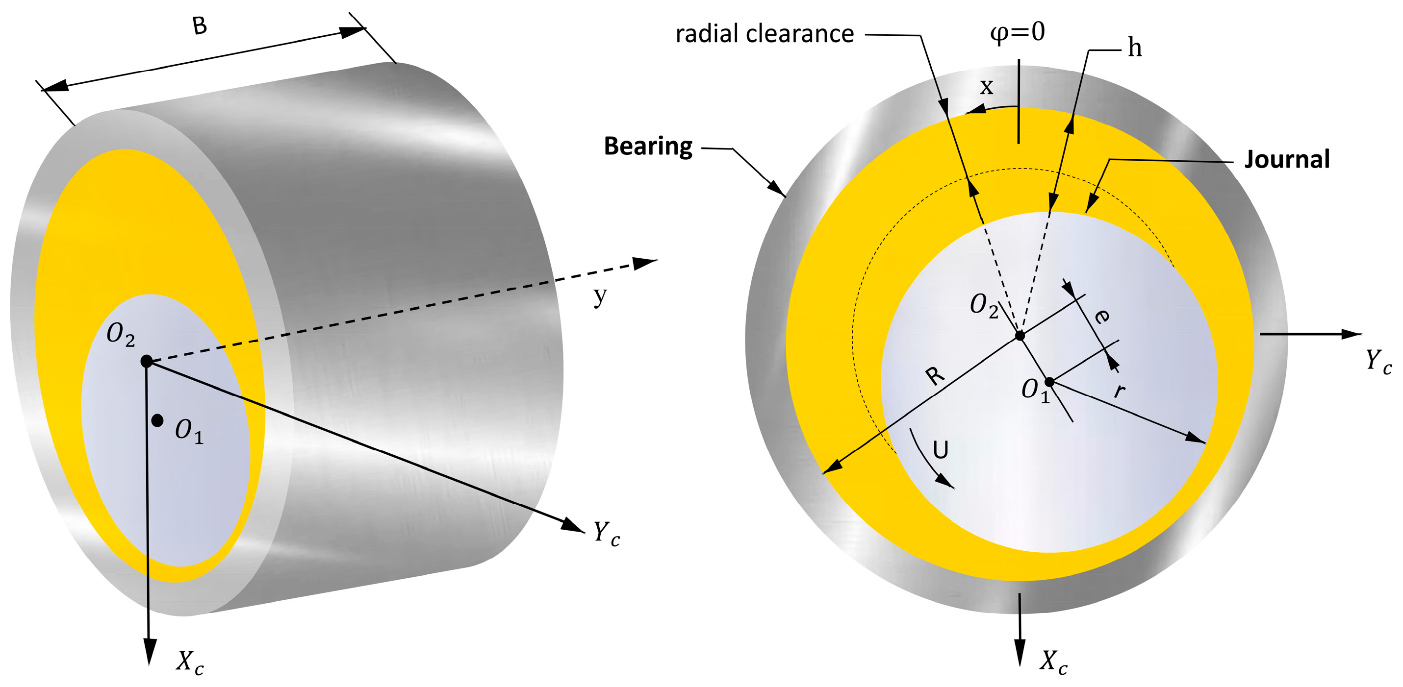
Journal bearings are frequently employed in rotating machinery. The rotation of the journal generates a pumping action, which, in turn, forms a lubricating film on the friction surface. The primary parameters of this component are illustrated in
Figure 1.
There are two coordinate systems in
Figure 1. Employing an alternative methodology can help ascertain the distribution of pressure and oil film thickness. The parameters depicted in
Figure 1 include the journal center
, the bearing center
, the journal radius
r, the bearing radius
R, shaft eccentricity ratio e, translational coordinates (
,
), angular coordinate (
x,
y), rotational speed
, and bearing width
B.
The oil film thickness
h is determined by the geometrical structure of the journal bearing and the position of the shaft center, and it is defined mathematically in Equation (1).
where
C is the radial clearance of the bearing,
,
is the circumferential length in the
direction.
and
denote the position of the shaft center
.
and
are dimensionless. The boundary conditions in this equation are assumed as follows:
. Note that the journal misalignment and texture are not considered here.
In the field of rotor dynamics, journal bearings are widely used to support rotating machinery because of their excellent LCC and long lifespan. The radial clearance between the journal and the bearing is filled with a thin layer of fluid. The pressure field of this fluid is described by the classical Reynolds equation, which is derived from considering mass and momentum balances.
This study used the Jakobsson–Floberg–Olsson (JFO) [
24,
25] model to predict lubricant flow in the journal bearing system. In addition, by incorporating the flow factor method proposed by Patir and Cheng [
26], the model fully accounts for the effects of surface irregularities on lubricant flow, and the equations are shown below:
where
is the oil film thickness,
p is the hydrodynamic pressure,
is the lubricant viscosity,
is the density of the lubricant,
is the time step, and
is the rotational speed. δ is the cavity fraction, which is related to the cavitation affected by the pressure.
and
are the pressure flow factors,
is the shear flow factor,
is the contact flow factor, and t is the time step.
σ denotes the comprehensive surface roughness and is calculated by
, in which
and
respectively, present the roughness of the journal and the bearing. Equation (3) is equivalent to the following conditions:
δ ≥ 0,
p ≥ 0,
p = 0.
This study utilizes the classical Greenwood and Tripp (GT) model [
27] to calculate the asperity contact pressure. The expressions were formulated as follows, and the effective elastic modulus is calculated using Equation (4).
In Equation (5),
is the asperity density, and
is the radius of the curvature of the asperity. The dimensionless parameter film thickness ratio
is an important criterion for the mixed lubrication transition from hydrodynamic lubrication.
represents a statistical function associated with the film thickness ratio
λ, and can be computed in accordance with Equation (6) [
28].
where
represents the hydrodynamic lubrication regime and
represents the mixed lubrication regime.
2.2. Performance Metrics for the Hydrodynamic Bearing
The journal bearing’s performance metrics chiefly revolve around its LCC, friction, and energy loss. The LCC is of particular importance as it indicates the maximum load that the bearing can support, thereby significantly impacting its stability and lifespan. Finding the maximum value of the LCC is helpful to determine the optimal film thickness, effectively reduce the possibility of rough contact, and play a key role in minimizing wear. The LCC can be calculated as follows:
The total friction is the sum of the viscous friction
and asperity contact friction
in the mixed lubrication regime, as indicated in Equation (8).
where
is calculated using the following integral formula:
where the terms
,
, and
represent friction-induced flow factors. Meanwhile,
can be calculated as follows:
where
is the asperity friction coefficient, and
= 0.02 in [
29].
2.3. Topology Optimization Principle
In general, topology optimization enhances the structural performance by optimizing material distribution within a design space, under specific constraints. It employs various mathematical and algorithmic approaches, primarily categorized into implicit and explicit methods. The explicit direct method, especially the Solid Isotropic Material with Penalization (SIMP) approach, is preferred due to its computational efficiency and physical clarity.
The SIMP method controls the material distribution continuity and pore count through a penalty coefficient, promoting binary material states to minimize ineffective pores. This method effectively handles multi-objective, multi-constraint scenarios and provides a robust optimization framework when combined with techniques such as the moving asymptotes method. This combination is particularly effective for complex, nonlinear problems, demonstrating high computational efficiency and robustness.
The Helmholtz filter introduces a grayscale value that needs to be reduced, necessitating the application of a smooth projection function. In variable density situations, this projection is performed using the density topology function, which employs a hyperbolic tangent-based method [
30]. The subsequent computation of the material volume factor, denoted as
θ, is performed using the following formula:
In this model,
β signifies the projection slope, while
indicates the projection point. To decrease the influence and visibility of the gray scale, an interpolation function is applied. Previously, the model predominantly used a solid isotropic material penalty function. The equation for the associated penalty material volume factor
is provided by Equation (12):
The SIMP index, denoted as , is employed to modulate the stiffness of the intermediate value, consequently diminishing the gray level, while denotes the minimum penalty volume fraction.
The grid’s management is contingent upon a physical field, namely, a hydrodynamic bearing. The approach to grid division significantly impacts the simulation’s accuracy and efficiency. Improper division can result in divergent or imprecise calculation outcomes. On the other hand, excessively dense grids may enhance calculation precision, but they also substantially escalate computational requirements. This could potentially reduce the computing efficiency or even precipitate system failure. Consequently, while preserving calculation accuracy is vital, striking a balance with suitable grid division is crucial for successful simulation.
3. Numerical Results
3.1. Model Verification
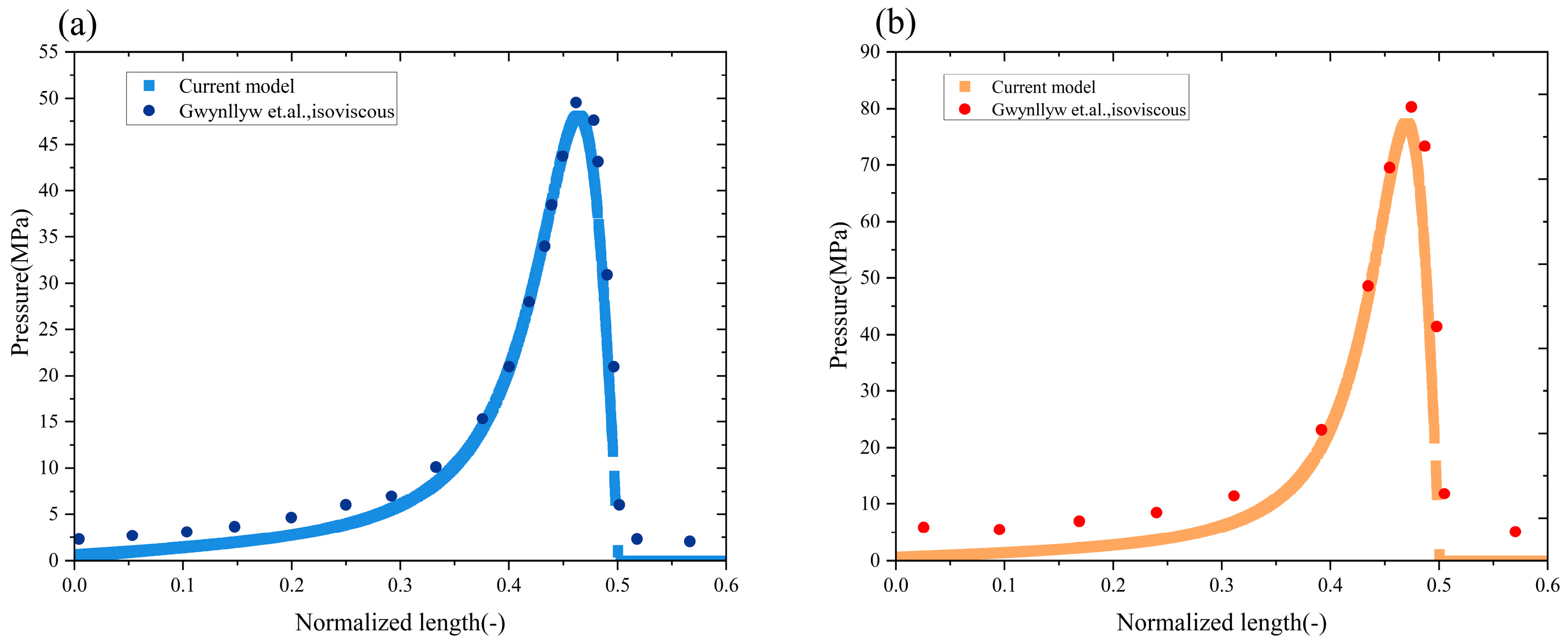
To verify the theoretical model, the simulation results of a journal bearing were compared with the computational results from reference [
31]. Gwynllyw et al. investigated the performance of an infinitely long journal bearing under isoviscous lubrication for different eccentricity ratios (
e/
C = 0.93 and
e/
C = 0.95). The parameters are provided in
Table 1.
Table 2 compares the verified pressure peaks with those from Gwynllyw’s study, and
Figure 2 presents a comparison of the pressure distributions obtained from the current model and from the work of Gwynllyw et al. These comparisons indicate that the relative error between the pressure peaks from the two methods is within 3%, which confirms the model’s high computational accuracy and acceptable error range.
Apart from this, to further validate the reliability of this model, it is compared with the experimental results of Patel et al. [
32]. In Patel’s experiment, the pressure peaks when using ISOVG46 lubricating oil in a brass bearing system under different loads and journal speeds is provided, and the experimental parameters are shown in
Table 3. As shown in
Table 4, a comparison is made between the pressure peak obtained from Patel’s experiment and that of the current model. The relative error of the pressure peak values between the two approaches is within 8%. Therefore, both the comparison with the experimental results and the aforementioned comparison with the numerical results validate the reliability of the model.
In topology optimization, threshold selection is crucial for the performance of the optimized result. Different thresholds produce textured shapes with different hydrodynamic properties. A lower threshold leads to an overly sparse structure, reducing the LCC. Conversely, a higher threshold makes the structure too dense, increasing material use and restricting fluid flow. Previous research shows that a threshold of 0.5 ensures structural stability while optimizing the hydrodynamic load-carrying performance [
33]. Therefore, this study sets the filter threshold at 0.5 to achieve shape optimization and enhance hydrodynamic performance.
A specific operating environment was chosen as the reference benchmark for all evaluation indicators in this study. This allows for a precise assessment of the performance improvements resulting from topology optimization. Hydrodynamic journal bearings were selected as the case study objects, with their relevant performance data presented in
Table 5.
3.2. Topology Optimization Result
The process of SIMP method topology optimization for textured bearings under hydrodynamic pressure involves iterative algorithms to adjust the topology and spatial distribution of the texture. The aim is to achieve a uniform oil film thickness and maximize the LCC. The process of topology optimization underwent 26 iterations.
Figure 3 depicts the initial state and the eight optimized solutions that exhibited the most pronounced texture alterations. In the initial state (0 in
Figure 3),
is recorded as
μm, while
is 1
μm.
As shown in optimization solutions 1 and 2, the refined texture morphology consistently appears as a curved strip, resembling flame contours, extending along the bearing surface. Optimization solution 3 generates a “bud-like” texture branch on the outer side of the bearing surface. This branch gradually enlarges in solutions 4 through 9, becoming more pronounced with each iteration. By solution 12, the “bud-like” branches have matured and stabilized, closely resembling the final design observed in optimization solution 26. This progression demonstrates a systematic evolution of the texture morphology, with the branches growing in complexity and size until they achieve a stable, optimized configuration. The incremental changes from solution 3 onward highlight the iterative refinement process that leads to the final hydrodynamic design.
Following topology optimization, the hydrodynamic bearing’s texture exhibits distinct distribution characteristics. The optimized texture, depicted in 26, aligns more closely with the principles of hydrodynamics, significantly enhancing the LCC and stability of the oil film. SIMP method topology optimization notably increased the oil film thickness, thereby improving the performance of the optimized bearing. At the same time,
Figure 4 reflects the topology optimization performance: when compared to pre-optimization measurements, the post-optimization h exhibited an increase of 57%. Throughout the iterative process from optimization solution 2 to solution 26, both
and
remained consistently stable at
μm and
μm, respectively. Simultaneously, the LCC, defined as the maximum load a bearing can support, sees a sharp increase of 110%. This significant enhancement substantially improves the stability and lifespan of the bearing, thereby providing a quantitative foundation for the engineering design of the bearing surface texture.
The optimized texture design significantly improves the oil film thickness distribution of the hydrodynamic journal bearing.
Figure 4 shows the comparison of the oil film thickness distribution before and after optimization. As shown in
Figure 4a, before optimization, the
is
μm and
is
μm, while, as shown in
Figure 4b, after optimization, the
increases to
μm. This indicates that the optimized texture can better control the oil film thickness distribution, making it stable over a wider range, thereby reducing the risk of lubrication failure caused by localized excessive or insufficient oil film thickness.
Through the application of SIMP method topology optimization, there is a notable enhancement in the distribution of fluid pressure. An illustration of the fluid pressure distribution and respective values, before and after optimization, is depicted in
Figure 5. In
Figure 5a, it is indicated that the maximum fluid pressure prior to optimization is denoted as 0.2845 MPa. On the other hand, in
Figure 5b, post-optimization, the maximum fluid pressure
reaches 0.584 MPa, marking a significant increase of 105% compared to pre-optimization levels. This substantial improvement underscores the capability of topology optimization to not only refine the oil film thickness distribution but also to significantly bolster the fluid pressure distribution. Consequently, the overall performance and operational efficiency of the system are enhanced. These findings provide a crucial theoretical foundation and technical support for the design and application optimization of hydrodynamic journal bearings.
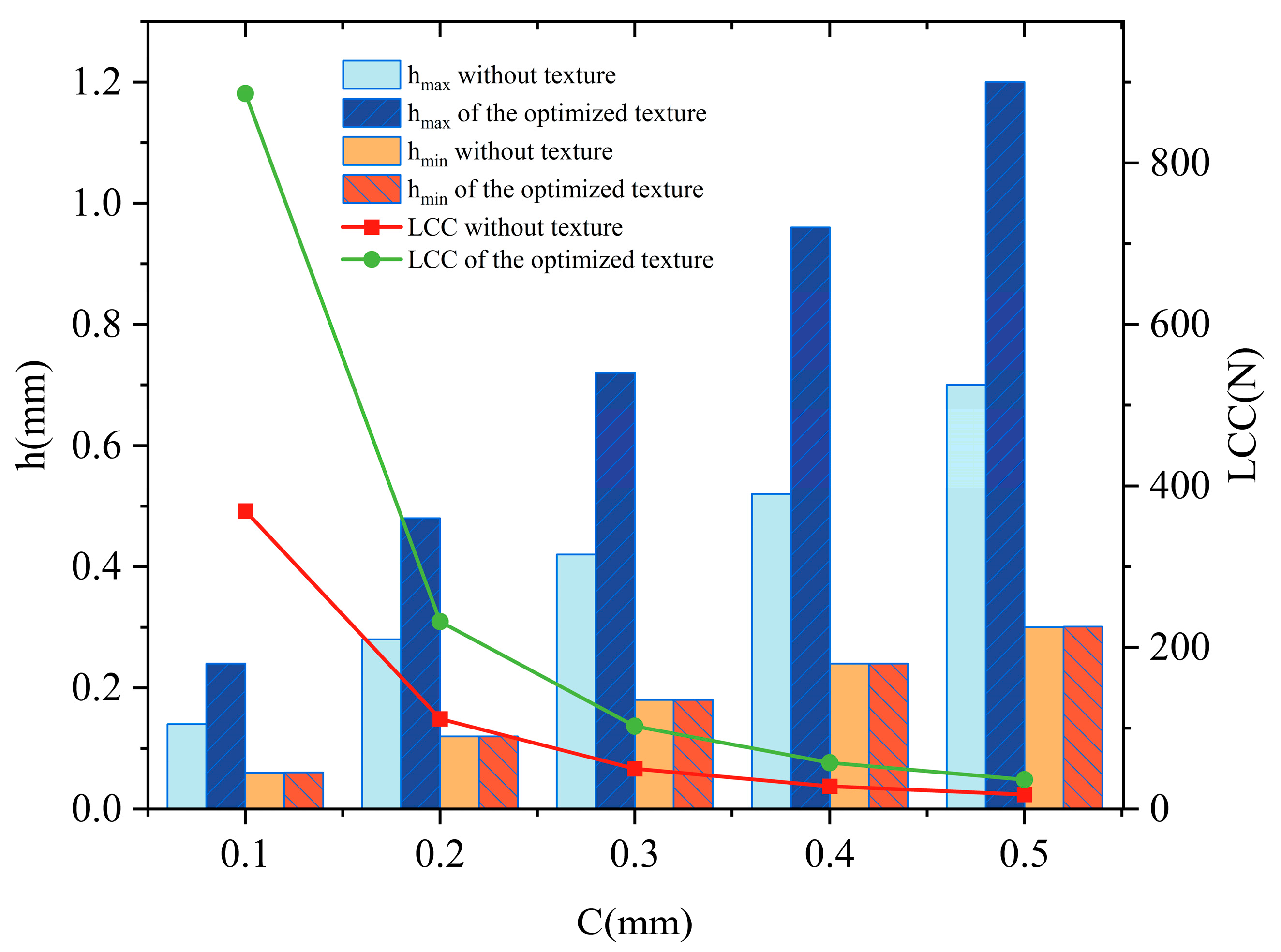
3.3. Influence of Journal Clearance on Optimization Result
This section discusses the impact of journal clearance on texture optimization. To maximize LCC, the SIMP approach is employed to determine the optimal surface texture pattern. By adjusting the journal radius and modifying the journal clearance, the study observes changes in the shape of the optimized texture, then further analyzes how journal clearance influences texture optimization. The journal clearance is varied between 24.5 mm and 24.9 mm, while other parameters remain consistent with those listed in
Table 1. The results of this optimization process are illustrated in
Figure 6, which includes visualizations of the material volume factor
θ, fluid pressure
p, and oil film thickness
h.
For
Figure 6a–c,
r varies between 24.5 mm and 24.7 mm. The texture’s primary structure resembles an “elongated shuttle” shape, characterized by a wide and thick mid-section that gradually tapers towards either end. This configuration exhibits notable continuity, devoid of significant morphological alterations, with only minor modifications in transitional zones. For
d, where the r is 24.8 mm, there is a pronounced “retraction” trend on the right side of the texture, while the extended form persists on the left. Nonetheless, the overall texture compactness has escalated. This image begins to show discernible differences compared to the preceding three. For
e, featuring a journal radius of 24.9 mm, the texture edge manifests a “bifurcation” pattern, reminiscent of “multi-lobed leaf expansion”. Originating from the foundational shuttle-shaped body, this texture evolves into intricate branching forms on both edges. The overarching structure transitions from a singular shuttle shape to an expansive form spanning multiple areas, markedly elevating the texture’s complexity. The generated textures are located in the exit corner of the sliding surface. This positioning significantly reduces the surface shear stress while maintaining the fluid pressure.
The changes in the shapes of the generated textures, which illustrate how optimization results vary with different journal clearances, enhance the fluid pressure and improve oil film thickness distribution in journal bearings. The results underscore the need for more detailed texture structures as clearances decrease, to optimize the flow field, enhance hydrodynamic pressure effects, and meet the hydrodynamic performance requirements of hydrodynamic journal bearings under limited clearances. This finding highlights the direct impact of clearance on topology optimization for texture design.
The analysis of the surface shear stress and fluid pressure
p distributions shows that the specific surface texture pattern under discussion can effectively reduce shear force while maintaining fluid pressure to the greatest extent possible. Under the same conditions, the LCC and h of an optimized texture are compared with those of common textured journal bearings. As illustrated in
Figure 7, the LCC exhibits a declining trend as the journal clearance increases. However, the topology optimization consistently proves crucial for enhancing journal bearing performance, particularly when the bearing clearance is minimal. For instance, with a bearing clearance of 0.1 mm, the LCC post-optimization increases by 139% compared to its pre-optimization value. While C is 0.5 mm, the LCC post-optimization rises by 105% relative to its pre-optimization value. Both
and
without texture gradually increase as the journal clearance expands. Through topology optimization, the
increases by 70%, while the
remains largely unchanged.
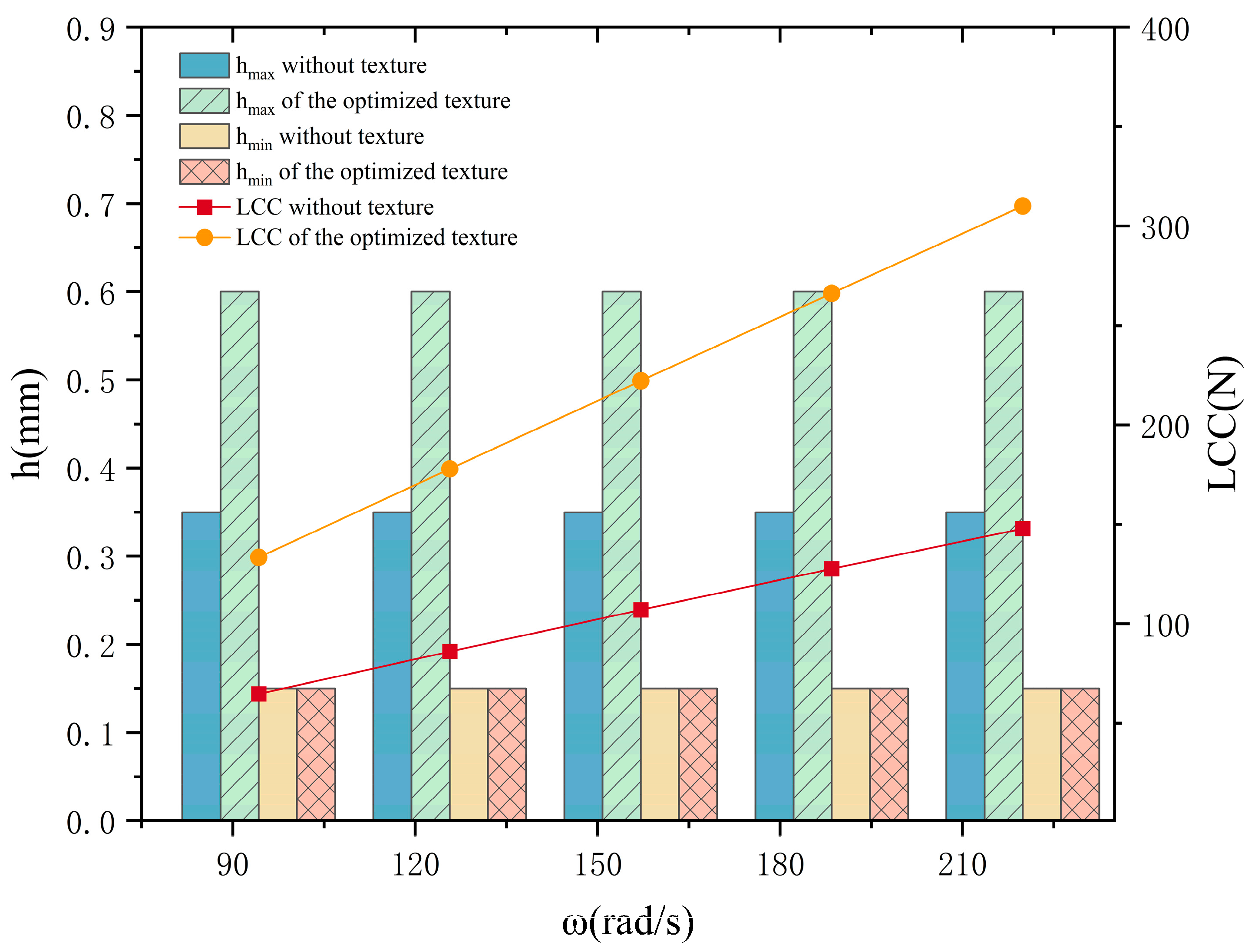
3.4. Influence of Rotational Speed on Optimization Result
Texture has the capacity to reduce friction, primarily through hydrodynamic and cavitation effects. However, to generate hydrodynamic pressure, relative motion is a prerequisite. This section examines the impact of rotational speed on texture optimization.
To enhance the universality of the research, this study focuses on changing the rotational angular speed ω to explore the impact of different rotational speeds on the optimization results. As ω escalates from 94.25 rad/s to 125.66 rad/s, the texture undergoes a notable transformation. Initially, at lower rotational angular speeds, the texture exhibits a “shuttle” shape, characterized by its broad and thick midsection with gradual extensions to either side in
Figure 8a. However, as ω increases, the texture begins to “shrink” on both sides, particularly the right, reducing its extensional reach and becoming more compact (b and c). This results in the formation of branches based on the original shuttle shape. In the later stages (d and e), distinct “bifurcation-like” fine structures emerge at the texture’s edges, transitioning it from a simple, regular form to a more intricate and complex morphology. Thus, at lower rotational angular speeds, the texture predominantly comprises large-area shuttle-shaped structures that regulate the flow field through an expansive morphology. Conversely, at higher speeds, the texture contracts and generates bifurcation structures, suggesting that increased rotational angular speeds necessitate more sophisticated texture shapes for optimizing fluid pressure distribution. This adaptation indicates that the texture modifies its edge structures and compactness in response to high-speed flow field characteristics, thereby enhancing the bearing’s lubrication effect and the LCC. This underscores the direct influence of the rotational angular speed on the SIMP topology optimization direction of texture.
Figure 9 indicates that, as the rotational angular speed increases, the LCC of the optimized textures rises almost linearly in comparison to regular textures. Through topology optimization, there is an increase in the LCC by a range of 106% to 110% relative to the pre-optimization values, with this growth rate amplifying alongside the increase in the rotational angular speed. However, both
and
are unaffected by the changes in the rotational angular speed. Additionally,
Figure 9 illustrates that although
has markedly improved post-optimization compared to pre-optimization values, there is a negligible difference in the
before and after optimization.
3.5. Influence of Shaft Eccentricity Ratio on Optimization Results
In addition, the shaft eccentricity ratio significantly influences the formation of the oil film, fluid pressure distribution, and the oil film thickness, making it a critical parameter in both design and application. As the shaft eccentricity ratio escalates, the wedge-shaped gap between the journal and the bearing becomes increasingly pronounced. This results in an acceleration of the speed at which the lubricating oil is drawn into the load area, subsequently leading to an increase in h. When the shaft eccentricity ratio reaches a range of 8% to 10%, h is within an optimal range. This not only ensures effective lubrication but also minimizes excessive friction.
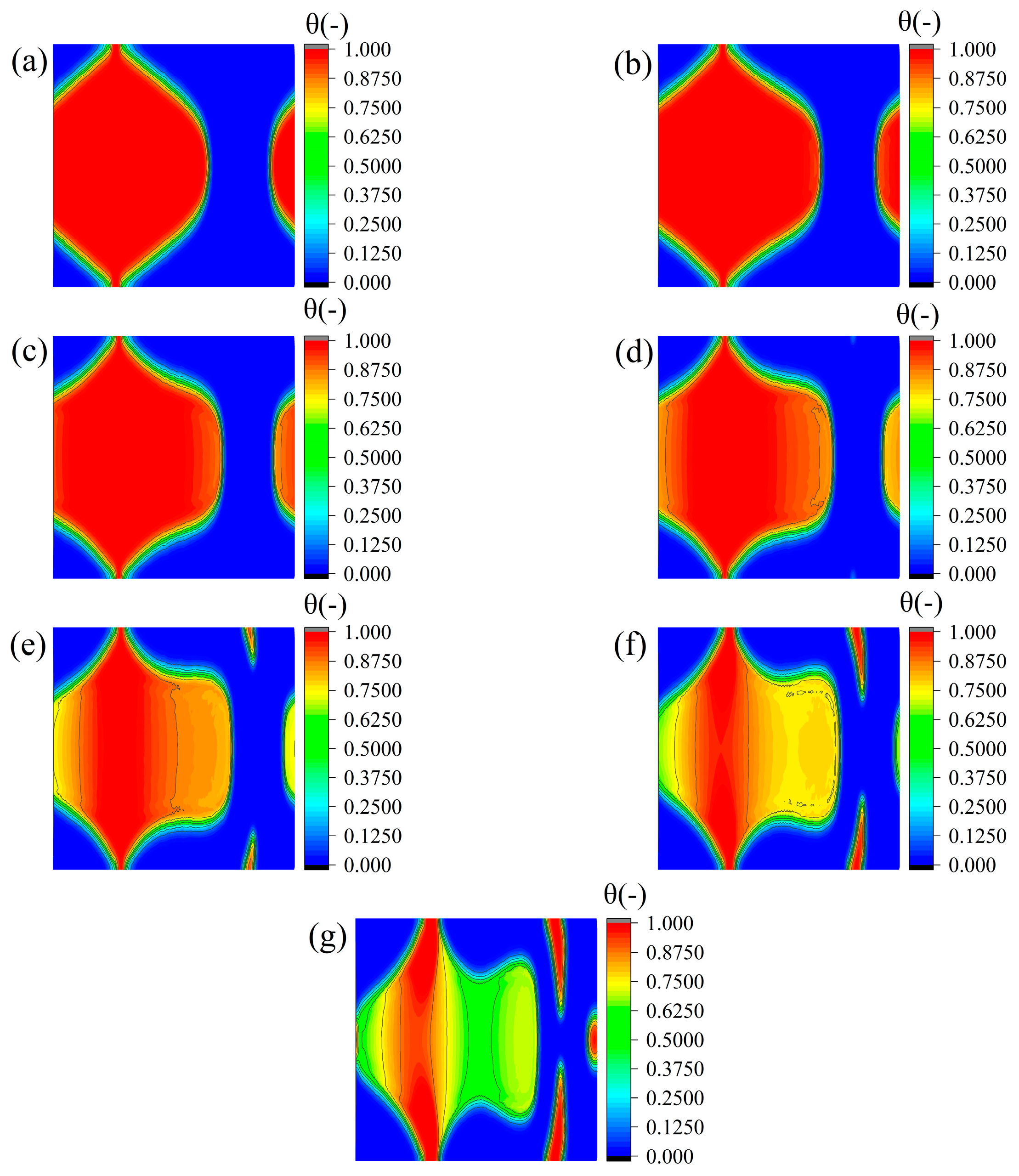
Figure 10 presents the results of topology optimization under varying eccentricity ratios, with the other parameters held constant. In
Figure 10a, where e is 0.1, the red high-θ area forms a distinct “spindle shape”. This shape is characterized by a deeper texture depth at the center, which gradually decreases toward both sides. From b to d, where e ranges from 0.2 to 0.4, the central region of deeper texture depth becomes narrower, and the depth on both sides decreases. From e to g, where e increases from 0.5 to 0.7, the central width continues to decrease. Sparse branch structures with depth gradients emerge on either side of the spindle shape. These branch structures become more prominent with an increasing shaft eccentricity ratio, evolving into a pronounced “lobed shape” at an shaft eccentricity ratio of 0.7. A reduced depth transition zone also appears in the center.
The morphological evolution begins with a concentrated spindle shape at lower eccentricity ratios and progresses to a complex structure with a deeper central core, lateral branches, and scattered depth domains. This transformation indicates that increasing shaft eccentricity ratios promotes texture optimization through material redistribution, particularly by adjusting the extent of deeper depth regions. The analysis shows that as the optimized area for texture design becomes smaller, its depth tends to decrease. This suggests that deeper textures require larger surface areas to achieve a significant improvement in LCC performance.
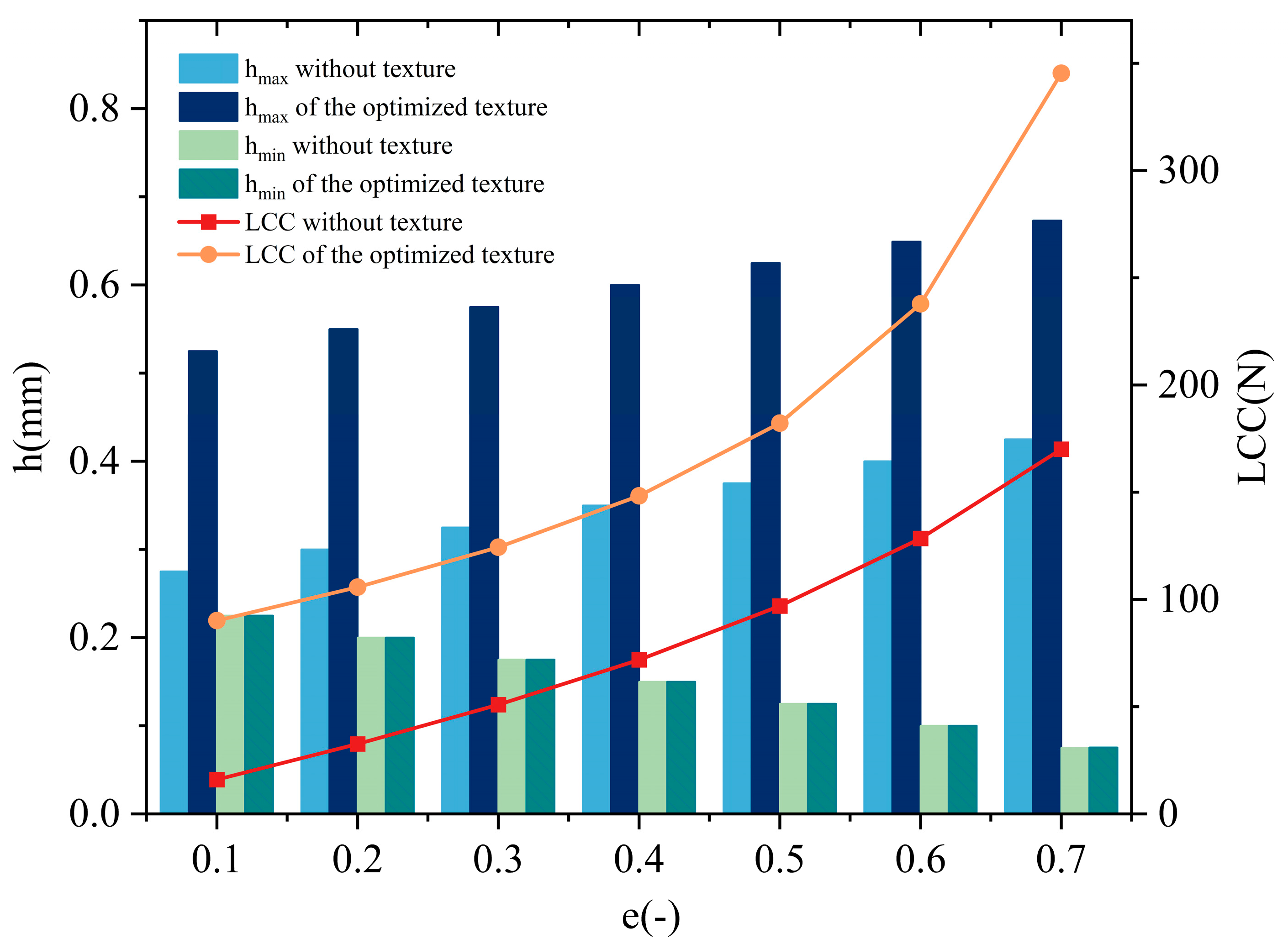
Figure 11 illustrates the impact of the shaft eccentricity ratio on the LCC and h, both pre-optimization and post-optimization, under identical conditions. As the shaft eccentricity ratio increases, the LCC shows a notable upward trend, with its growth rate accelerating in line with the increase in the shaft eccentricity ratio. The effect of the topology optimization on the LCC is more pronounced at lower eccentricity ratios. For example, at a shaft eccentricity ratio of 0.1, the optimized LCC increases by 464% compared to its pre-optimization value, significantly enhancing the bearing performance. However, at a shaft eccentricity ratio of 0.7, the growth rate is 104%, still indicating a substantial improvement in the LCC. Meanwhile, as the shaft eccentricity ratio increases, both the
and
gradually rise. Topology optimization notably boosts the
, but the growth rate of the
decreases with the increasing shaft eccentricity ratio. For instance, when e is 0.7, the growth rate reaches 90%, while when e is 0.7, it drops to 58%. Notably, the optimized
remains relatively consistent.
4. Conclusions
In this study, the SIMP method topology optimization is used to investigate the influence of surface texture on the performance of journal bearings under different parameters. The main research conclusions are as follows:
(1) The findings suggest that journal clearances significantly influence the optimization of the texture topology and the overall bearing performance. A larger clearance results in a more relaxed, “shuttle” shape for the texture, while a smaller clearance leads to complex bifurcations. Following optimization, the LCC and h increase significantly, with this effect being particularly pronounced when the clearance is small.
(2) The findings suggest that the rotational speed plays a pivotal role in texture optimization. At lower rotational speeds, the texture manifests as a broad, robust “shuttle” shape; however, at elevated speeds, it narrows and evolves to exhibit branching, thus increasing its morphological complexity. This optimized texture enhances both lubrication and the LCC. The LCC of the refined texture demonstrates a linear relationship with increasing rotational angular speed. Notably, the peak h shows significant enhancement but remains unaffected by rotational angular speed variations, whereas the minimal value remains largely consistent.
(3) Following optimization, at a low shaft eccentricity ratio, the unilateral texture depth is deep with few branches. However, as the shaft eccentricity ratio increases, the number of texture branches increases significantly and the middle depth decreases, creating a more complex texture. Through the optimization process, both the LCC and h are improved. It should be noted that these enhancements are especially significant at a lower shaft eccentricity ratio.
In addition, at high shaft speeds, the effects of fluid inertia can become non-negligible. However, the JFO model used in this work is based on assumptions that are valid in the low-inertia regime. This limitation should be acknowledged. Furthermore, the effect of optimized textures on the transient performance of journal bearings, encompassing wear, starting, and stopping processes, also requires consideration. It is ongoing work.


