Article

Study of Corrosion, Power Consumption, and Wear Characteristics of Herringbone-Grooved Fan Bearings in High-Temperature and High-Humidity Environments

Department of Power Mechanical Engineering, National Formosa University, Yunlin 632, Taiwan
*
Author to whom correspondence should be addressed.
Lubricants 2025, 13(6), 245; https://doi.org/10.3390/lubricants13060245
Submission received: 2 April 2025 / Revised: 20 May 2025 / Accepted: 24 May 2025 / Published: 28 May 2025
(This article belongs to the Special Issue Recent Advances in Tribological Properties of Machine Tools)

Abstract

:
Fans are essential electronic components for heat dissipation in electronic systems, with fan bearings being critical parts that determine fan performance and lifespan. This paper investigates the corrosion, wear, power consumption, temperature, and vibration characteristics of a newly designed and manufactured powder metallurgy bearing with herringbone oil grooves for fans under high-humidity and high-temperature conditions. Corrosion experiments on iron–copper powder metallurgy bearings show that a higher environmental temperature and humidity result in greater corrosion current and reduced corrosion resistance. Bearings operated under high humidity (85% RH) and a high temperature (80 °C) for 0, 3, and 8 days, respectively, revealed that wear and corrosion occur simultaneously. The longer the operating time, the more significant the wear and corrosion. After 3 and 8 days, the lubricating oil flow in the oil grooves decreased by 9.8% and 51.5%, respectively. When bearings subjected to varying degrees of corrosion were tested under the same standard operating conditions, it was found that the bearings corroded for 3 and 8 days, resulting in a significant increase in the number of wear debris particles, higher RMS vibration values, and a power consumption increase of 6.9% and 7.8%, respectively. The percentage of iron elements on the surface gradually decreased, with the copper elements being the primary wear particles during the wear process. However, due to the increased clearance between the rotating shaft and the bearing caused by wear, the fan temperature slightly decreased with increased surface wear.

1. Introduction

Due to the growing performance needs of electronic devices, automobiles, and instruments, their heat dissipation is on the rise, demanding cooling fans with progressively better performance. Fan bearings are crucial components in any device that uses a fan for cooling or ventilation. They are responsible for supporting the fan blades and allowing them to rotate smoothly and efficiently. The type of bearing used in a fan can significantly impact its performance, lifespan, and noise level. Fluid Dynamic Bearings (FDBs) are the most advanced type of fan bearing. They use a thin layer of fluid to lubricate the moving parts, resulting in very low friction and noise levels. FDBs also have a long lifespan and are highly reliable. However, they are more expensive than other types of bearings [1,2,3]. The herringbone bearing is a type of FDB that uses a thin film of fluid to separate the moving parts. The herringbone grooves help to pump the fluid and maintain a stable film, even at high speeds. This results in lower friction, less wear, and quieter operation compared to traditional bearings [4,5,6].
Porous bearings, produced via the sintering of compressed metal powders, feature a porosity of approximately 25% by volume, enabling oil retention within the pores. Due to its favorable electrical and thermal conductivity, as well as its low coefficient of friction, copper powder is most commonly used in self-lubricating bearings, which consume roughly 70% of the total copper powder production [7,8,9,10]. It has become a key manufacturing process for fan bearings. Over the years, various materials mixed with copper have been used to enhance performance. Incorporating graphene to reinforce copper offers a practical means to improve the mechanical and abrasive resistance characteristics of copper-matrix composites [11]. A Cu–Sn porous bearing containing 90% copper and 10% tin can effectively reduce the coefficient of friction [12,13]. During the experiment, two commercial oils (SAE 20W50) exhibited friction coefficients of approximately 0.101–0.097 in the initial stage due to surface contact. Subsequently, they entered hydrodynamic lubrication, with the friction coefficients being approximately 0.067–0.049 [12]. Ball-on-disk tribometer testing of Fe–Cu–Sn porous bearings demonstrated that a composite containing 0.5 wt% MoS2 and 2.0 wt% ZrO2 exhibited lower friction (0.128) and wear rates [14]. Bronze-matrix composites, fabricated by powder metallurgy by utilizing graphite lubrication, demonstrated a reduced wear rate when titanium carbide (TiC) was applied to the graphite surface relative to pure bronze [15].
However, herringbone-grooved journal bearings (HGJBs) exhibit an additional self-pumping pressure effect, enhancing bearing stability [16], load capacity [17], and reducing friction loss [4,18]. Tomioka and Miyanaga [16] demonstrated through stability charts that varying the external spring coefficients and damping ratios significantly improves the HGJB’s stability. Jang and Yoon [18] derived Reynolds equations for both smooth shafts in grooved sleeves and grooved shafts in smooth sleeves, finding that the smooth shafts in grooved sleeves resulted in substantially higher frictional power loss compared to the grooved shafts in smooth sleeves. The occurrence of third-body particles or wear debris is inherent in the operation of lubricated interfaces, and these particles influence friction and vibration characteristics [19,20,21]. It is especially important to note that both the interfacial clearance and surface roughness significantly affect the lubrication regime at the third-body interface, and the size of the third-body particles is another critical parameter [22,23]. Nevertheless, herringbone porous bearings have received limited attention in research. Therefore, this paper manufactured herringbone-grooved oil grooves on the surface of powder metallurgy bearings and conducted characteristic analyses under high-temperature and high-humidity conditions to understand their performance changes when applied in extreme environments.
Heat dissipation fans have a wide range of applications, typically in low-temperature environments, to maintain high heat dissipation efficiency. However, in steel mills, textile factories, paper factories, or heat treatment plants, the temperature and humidity are relatively high. Especially in high-temperature working environments during rainy days, high temperatures and high humidity inevitably cause bearing corrosion. However, how high-temperature and high-humidity corrosion and wear affect the vibration and energy consumption of herringbone-grooved journal bearings is rarely discussed in depth in the existing literature. This is the focus of this paper.

2. Experimental Methods and Workpiece

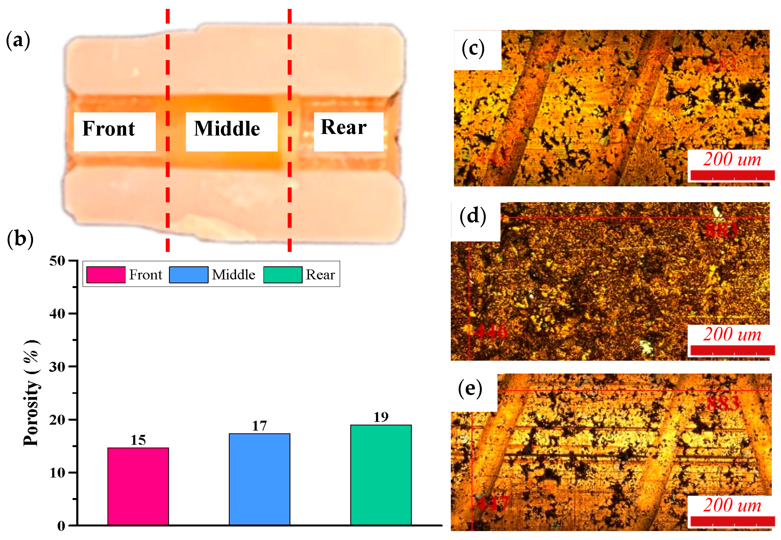
Figure 1 shows the fan appearance and powder metallurgy bearing assembly designed and manufactured in this paper. The bearing is installed in the center of the fan. The inner surface of the bearing sleeve is machined with herringbone oil grooves, utilizing die-casting techniques at the front and rear ends. The inner diameter of the bearing sleeve is 3.0 mm, and the length is 12.0 mm. Figure 2a divides the inner surface of the sleeve into three regions: a middle region without oil grooves and front and rear regions with herringbone oil grooves. The porosity of these three regions was measured using optical methods, as shown in Figure 2b, which shows that the average porosity of the bearing sleeve surface is 17.0%. Since the oil grooves can assist more lubricant to enter the interface than the porous surface, the bearing in this paper can have less porosity than the powder metallurgy bearings without oil grooves, thereby increasing the bearing strength. The rotating shaft is made of chromium-molybdenum steel material to increase its rigidity.
The experimental procedure of this paper is divided into two parts. The first part analyzes the corrosion current of the bearing under different temperatures and humidity to illustrate its static corrosion resistance. The environmental conditions include three types: 25 °C + 35% RH, 45 °C + 60% RH, and 80 °C + 85% RH. The first type is the laboratory environment, and the latter two harsh conditions were tested for 3 days and 8 days to understand the basic corrosion resistance of this bearing under different temperatures and humidity. The second part analyzes the corrosion and wear effects of the powder metallurgy bearing under high-temperature and high-humidity conditions of 80 °C + 85% RH, with the bearing running for 0 days, 3 days, and 8 days to facilitate the explanation of the vibration, temperature, wear, and corrosion changes and causes under general test conditions (45 °C and 60% RH). Figure 3 illustrates the corrosion testing apparatus. The electrolyte solution employed in this equipment consisted of a 3.5 wt% NaCl solution. A platinum (Pt) electrode served as the counter electrode, while a saturated calomel electrode (SCE, Hg/Hg2Cl2) was utilized as the reference electrode. The test temperature was maintained at 25 °C, and the duration of the corrosion scan was 1800 s.
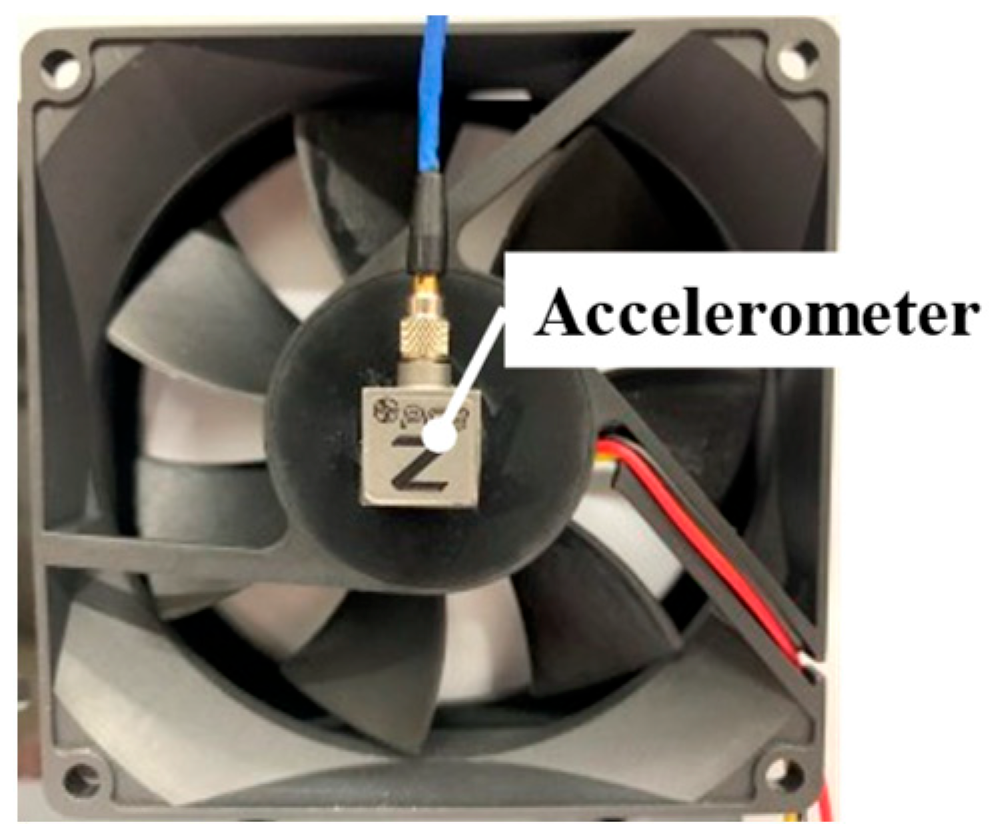
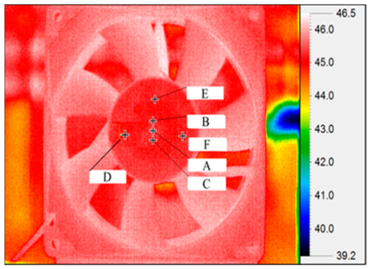
The basic properties of the lubricating oils used in this study are shown in Table 1. The environmental control equipment for the porous bearing experiment is shown in Figure 4. The humidity measurement range is RH 20% to RH 90%, and the temperature measurement range is 0 °C to 90 °C. To measure the impact of the bearing affected by high temperatures and high humidity on a fan’s vibration, an accelerometer was placed at the center of the fan’s surface, as shown in Figure 5. The accelerometer has acquisition frequencies and an acceleration of 2.0~5000 Hz and 0.5 g, respectively. Wear debris particles are an important indicator of performance in powder metallurgy bearings. Therefore, a particle counter (PAMAS S40) was used to measure the change in wear debris particle size, as its measurement range was from 0.5 μm to 20 μm. The surface morphology and oil groove size of the bearing sleeve before and after the operation were measured using an optical roughness tester (Bruker Contour GT-K, Tucson, AZ, USA) with a surface accuracy of ±0.1 nm. In this paper, temperature measurements on the accelerometer’s back surface were conducted using an infrared thermometer with a resolution of 0.05 °C and a pixel size of 10.0 μm, as illustrated in Figure 6.

3. Results and Discussion

3.1. Measurement of Basic Properties

Figure 7 shows the oil groove dimensions of the fan bearing designed in this paper under laboratory environment conditions (25 °C + 35% RH). The oil grooves provide a larger percentage of lubricant, which is necessary for bearing lubrication. The average depth of the oil grooves is 4.4 μm, and the average width is 107.6 μm. The black areas in the figure are surface pores, which can also afford lubricant to enter the bearing interface during operation. The surface composition of the bearing was analyzed by EDS composition analysis, as shown in Figure 8. The main components are copper (84.2%) and iron (8.5%). The corrosion situation and the surface wear depth and composition changes of the bearing caused by the operation will be explained in Figure 9, Figure 10, Figure 11 and Figure 12 later.
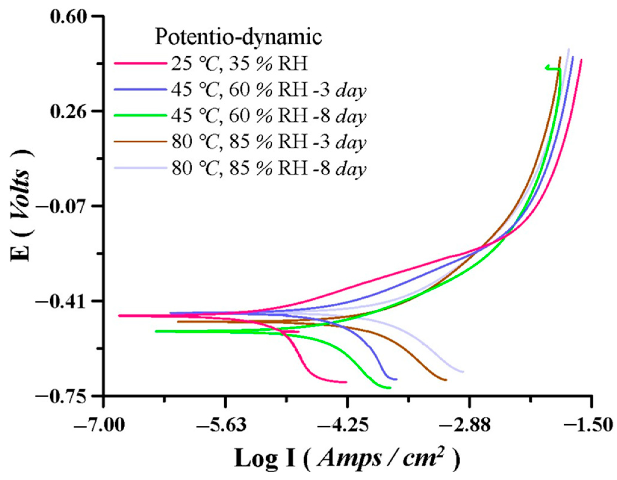
To investigate the static corrosion resistance of this bearing, corrosion experiments were carried out using the equipment in Figure 3 and Figure 9, which show the polarization curve. Table 2 presents the corrosion current data for the bearing immersed in a 3.5% NaCl solution. Figure 9 shows the polarization curve under different corrosion conditions. The coated display shows that the corrosion potentials, Ecorr, from low to high temperatures are −0.48 V, −0.32 V, and −0.26 V, respectively. The higher the corrosion potential, the less likely corrosion occurs. Table 2 presents that under a laboratory environment of 25 °C + 35% RH, the corrosion current of the iron–copper bearing is 1.29 × 10⁻⁶. However, after being placed in an environment of 80 °C + 85% RH for 3 days and 8 days, its corrosion current increased to 6.04 × 10⁻⁵ and 7.55 × 10⁻⁵, indicating a significant decrease in its corrosion resistance. Of course, under the 45 °C + 60% RH environment, when the time increased from 3 days to 8 days, its corrosion potential also increased with time, but it was still less than the corrosion current value of 80 °C + 85% RH. In summary, the surface corrosion of this bearing increases with an increase in temperature, humidity, and time.

3.2. Performance of Porous Bearing Under High Temperatures and Humidity

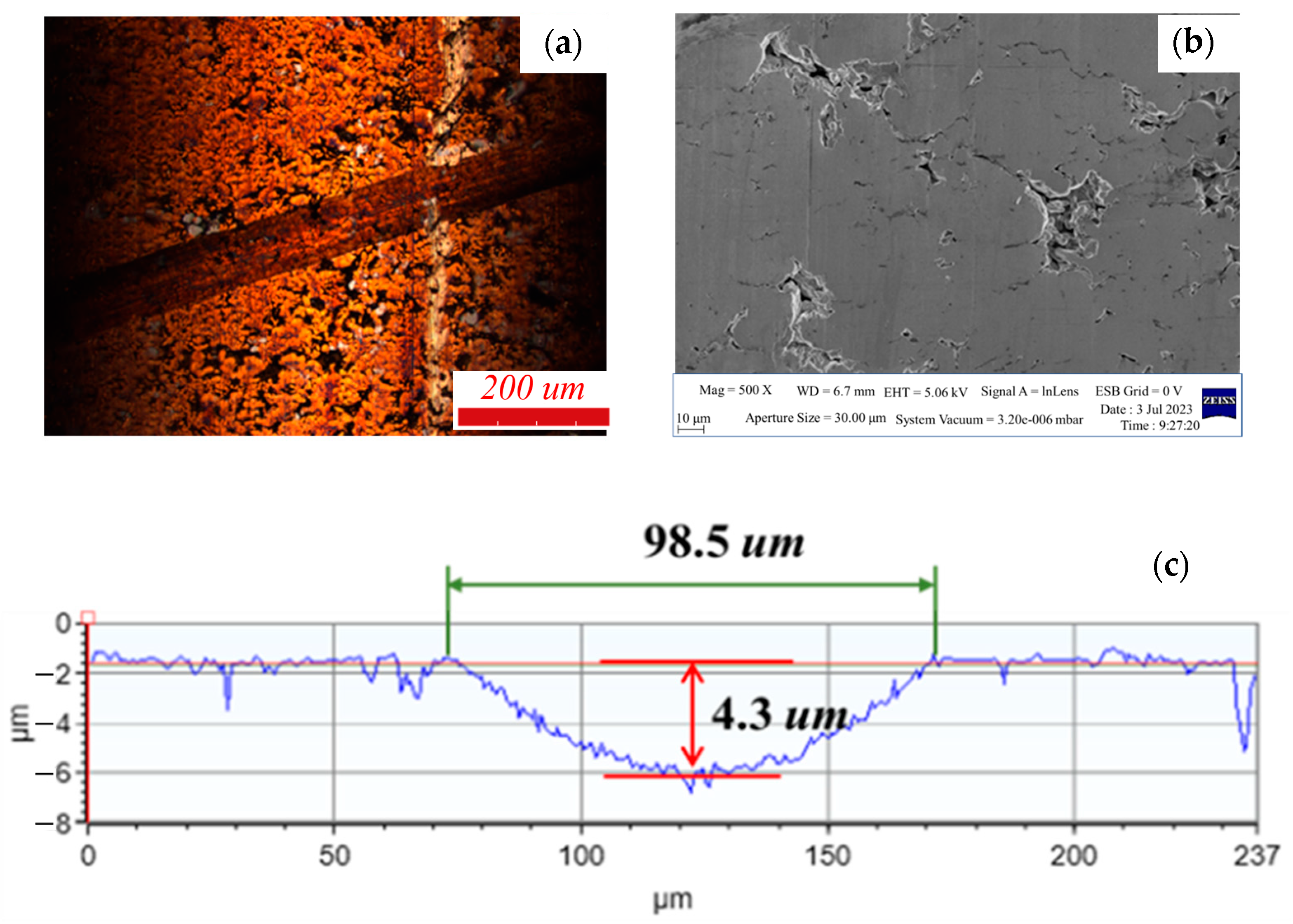
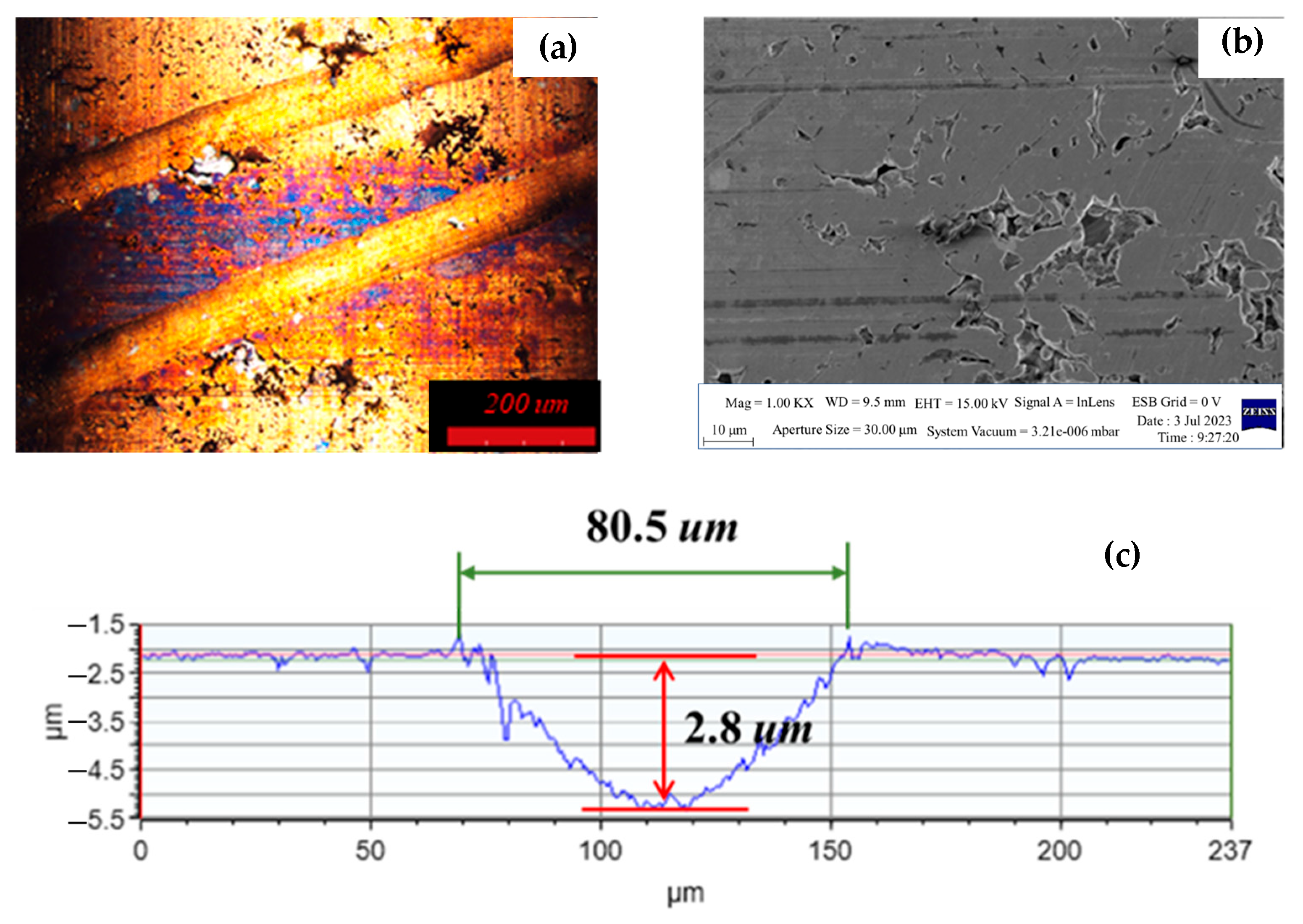
To understand the surface wear performance of the bearing during long-term operation in a corrosive environment, the bearing was installed in a fan and operated at 12 volts and 2100 rpm in a humidity- and temperature-controlled chamber. Figure 10 illustrates the OM image, SEM image, and oil groove changes of the bearing operated at 80 °C and 85% RH for 3 days. Figure 11 shows that the oil groove depth decreased from the original 4.4 μm to 4.3 μm after 3 days and further decreased to 2.8 μm after 8 days. Obvious wear marks are visible in the image. At the same time, the oil groove width also gradually decreased to 80.5 μm, indicating that corrosion and wear occurred simultaneously during operation under these conditions. As wear gradually increased and reduced the oil groove space, the lubricant volume decreased to 9.8% and 51.0% after 3 days and 8 days, respectively, resulting in a reduction in the lubricant’s ability to provide lubrication from the oil groove.
To understand the bearing’s lubrication regime and interfacial characteristics, the relationship between specific film thickness and wear is analyzed below. The Reynolds equation used to analyze the oil film thickness is as follows [24]:
x ( h 3 p x ) + z ( h 3 p z ) = 6 U μ h x  
where h is the oil film thickness, x is the axial direction, z is the radial direction, p is the pressure, μ is the lubricant viscosity, and U is the velocity. Based on the lubricant properties in Table 1 and the operating condition of 2100 rpm, the calculated oil film thickness is 4.52 μm [24]. Given that the composite surface roughness (σ) of the bearing at the initial stage, as well as after 3 days and after 8 days, is 0.67 μm, 0.92 μm, and 1.54 μm, respectively, the wear depths of the bearing after 3 days and 8 days are 0.1 μm and 1.6 μm, as shown in Figure 10 and Figure 11. Therefore, the specific film thicknesses (h/σ) are 6.75, 5.02, and 3.97, respectively. These values indicate that the bearing operates under hydrodynamic lubrication during stable operation. It is noteworthy that the gradual decrease in specific film thickness with the increasing operating time is due to the increase in surface roughness caused by corrosion. Based on the wear depth in Figure 10, the estimated wear rate for the first 3 days is 1.58 × 10⁻⁴ mm3/h, and the average wear rate for the subsequent 5 days is 1.52 × 10⁻³ mm3/h. This indicates that the primary mechanical wear occurs during the running-in process in the first three days [12], while the corrosion wear rate in the following 5 days is greater than the sum of the mechanical wear rate and the corrosion wear rate.
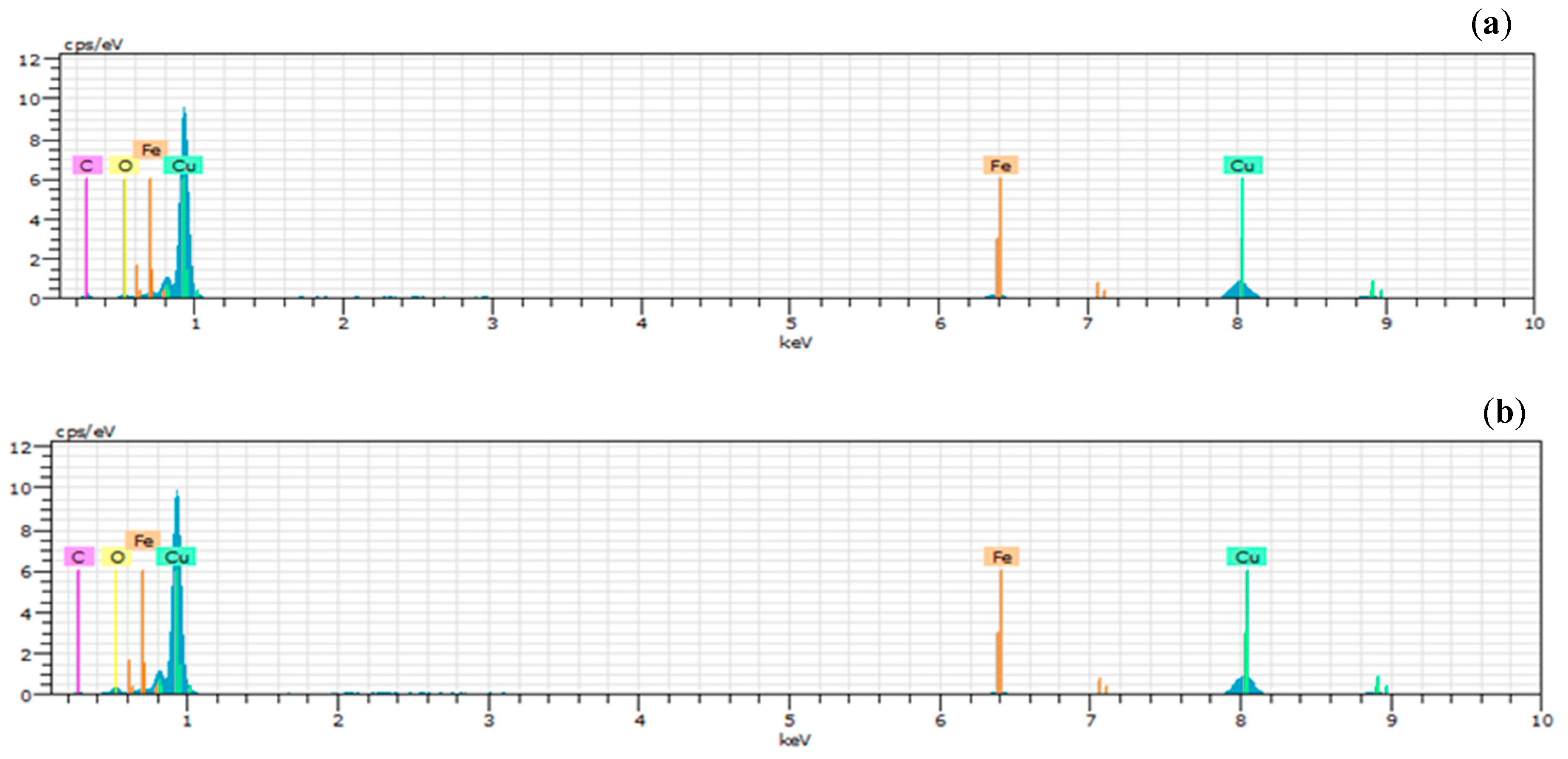
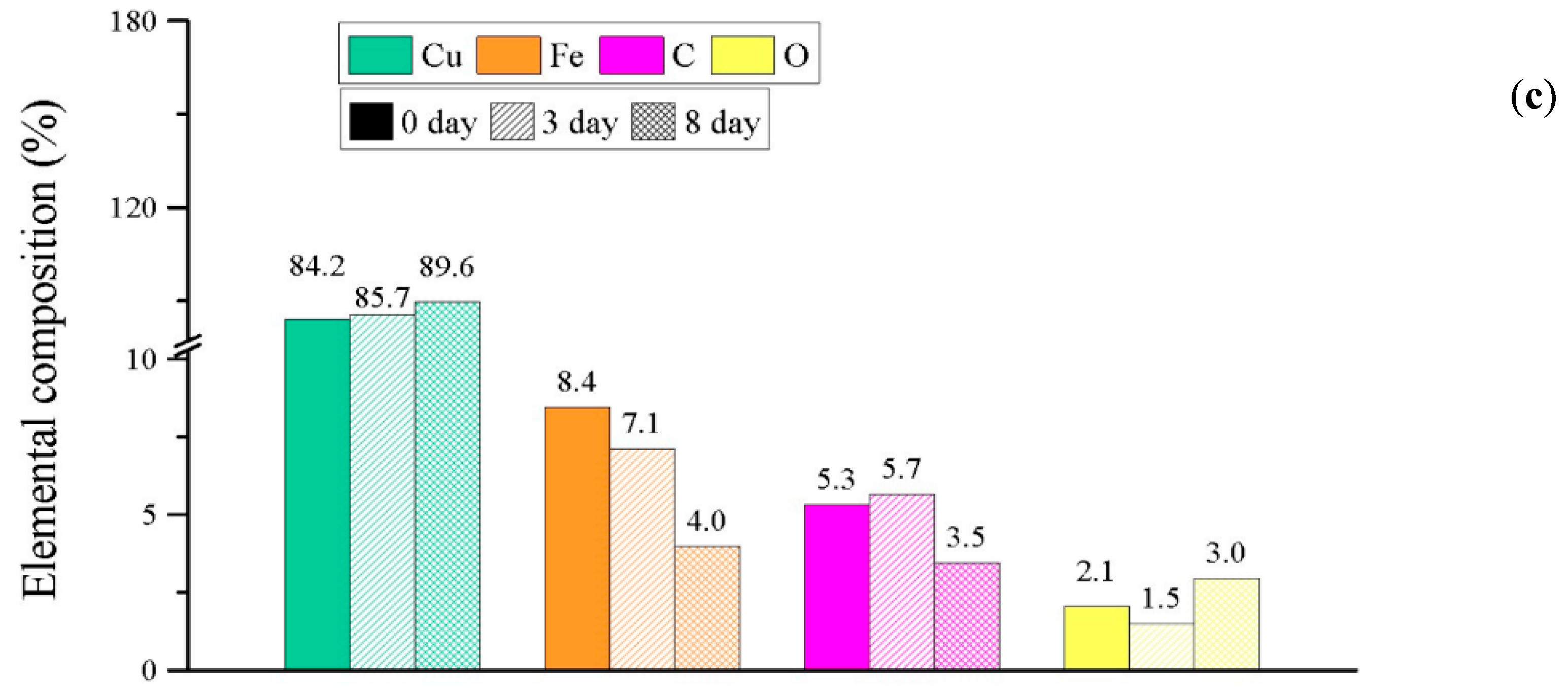
Figure 12 illustrates the changes in the surface material composition of the bearing after operating at 80 °C + 85% RH for different durations. Figure 12a,b show the EDS spectra of the surface material, indicating the presence of Fe, Cu, C, and O, which are the same elements found in the new bearing in Figure 8b. Combining Figure 8b and Figure 12a–c, the changes in the percentage composition of Fe, Cu, C, and O on the bearing surface over different operating durations are described. The graph shows that the Fe content significantly decreases during operation while the Cu content percentage increases. This is because the standard electrode potential of iron (−0.44) is lower than that of copper (+0.337). Therefore, in a high-temperature and high-humidity environment, the iron component corrodes first, leading to a decrease in the iron content percentage and an increase in the copper content percentage.
The operational test conditions for general powder metallurgy bearings are typically conducted at a fixed temperature of 45 °C and a humidity of 65% RH. Therefore, the experiment in Section 2 of this paper involves subjecting bearings with varying degrees of corrosion damage to a 20-day accelerated operational test (45 °C + 65% RH) to analyze the performance changes in vibration, wear, energy consumption, and temperature rise. Figure 13a shows the vibration RMS value changes during the 20-day operation after the bearings were subjected to three different operating conditions. It demonstrates that the vibration RMS value increases with the number of days in a high-temperature and high-humidity environment. Under the 8-day operating condition, compared to the 0-day condition, not only is the vibration value change greater, but the average vibration value also increases by approximately 1.40 times (from 0.033 to 0.046), as shown in Figure 13b. Figure 13b illustrates the average vibration values and average current values of the bearings after being subjected to different durations of high-temperature and high-humidity environments during the 20-day standard experiment. From the graph, it is observed that the current consumption increases with the number of days. Since the voltage input in this experiment is consistently 12 V, it indicates that the energy consumption increases with the number of days in a high-temperature and high-humidity environment. A 6.9% and 7.8% rise in power consumption was observed for 3-day and 8-day corroded bearings, respectively, compared to the new bearing. This increase in current consumption is likely influenced by vibration, as demonstrated in Figure 13b.
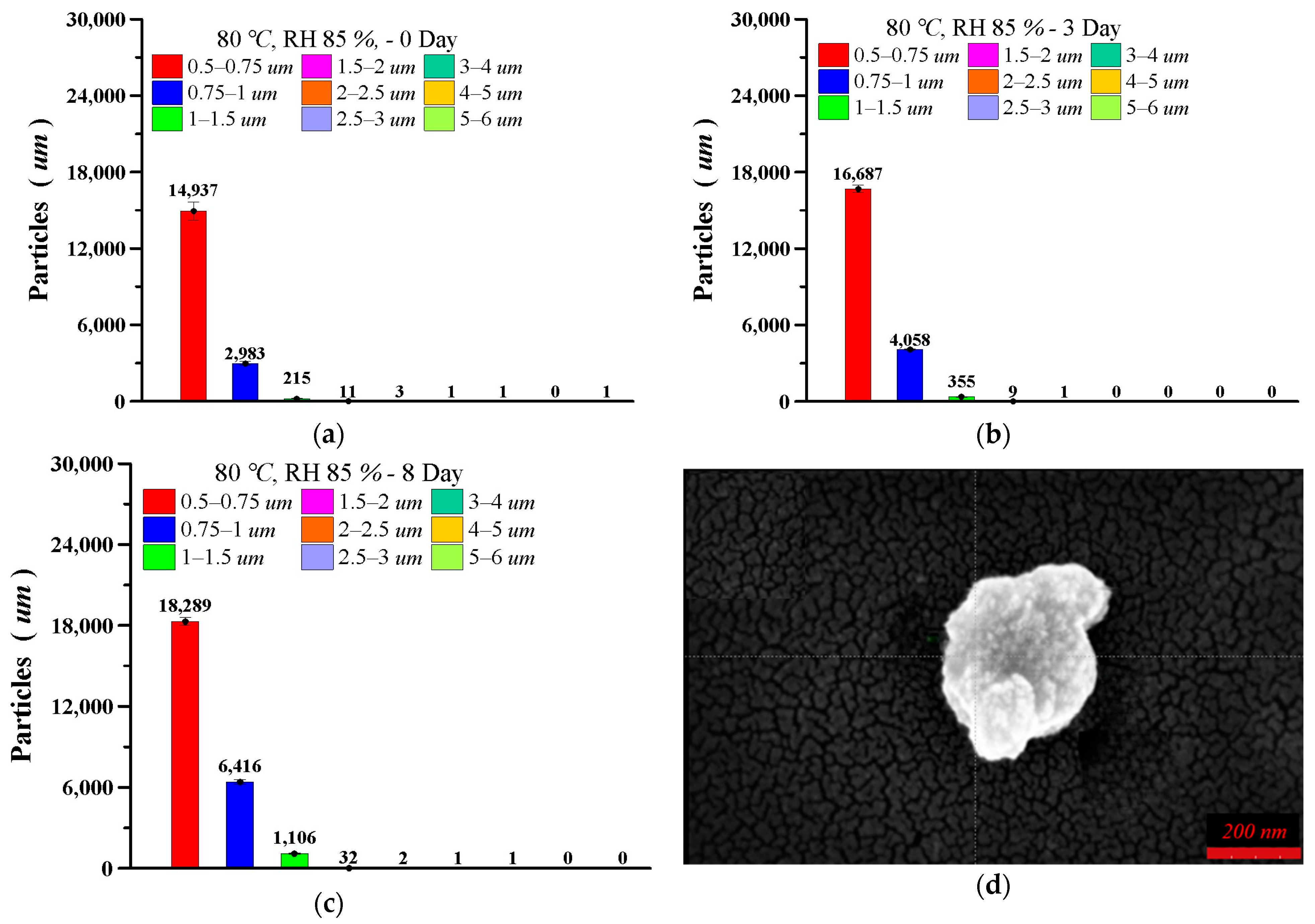
This bearing was manufactured by powder metallurgy pressing, which makes it prone to wear debris mixing into the lubricating oil. Figure 14 illustrates the particle size and quantity of the wear debris extracted from the lubricating oil after 20 days of operation under the same experimental conditions for bearings with varying degrees of corrosion. Figure 14a–c shows that the number of particles in the 0.5 μm~0.75 μm range increased from 14,937 particles for the new bearing to 16,687 particles for the 3-day corroded bearing and further increased to 16,687 particles for the 8-day corroded bearing. Similarly, the number of wear debris particles in the 0.75 μm~1.0 μm and 1.0 μm~1.5 μm size ranges also increased with the severity of corrosion. This increase in wear debris particles also contributes to the increase in the vibration RMS values observed in Figure 13. Changes occurred in the (a) vibration RMS value and (b) average current consumption vs. the vibration RMS value during 20 days of operation for bearings under different levels of corrosion [25]. As for the particles that were larger than 1.5 μm, they were scarce under all three operating conditions. This indicates that bearings with higher degrees of corrosion, therefore, experience more severe wear during subsequent operation. Figure 14d shows the SEM image of the wear debris particles, which are slightly larger than 0.5 μm. The EDS elemental analysis shows that the main element is copper, as shown in Table 3.
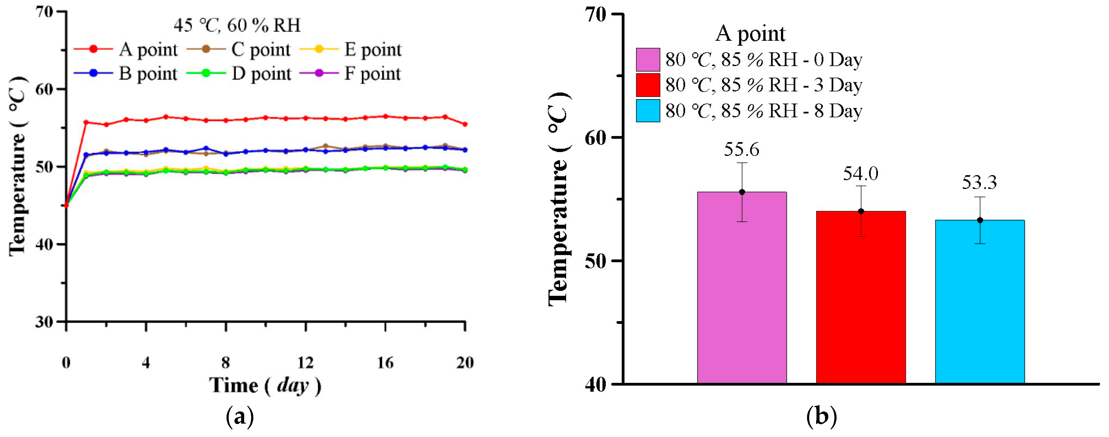
Figure 15 illustrates the temperature distribution on the bearing end cap surface of the fan. The positions A, B, C, D, E, and F are shown in Figure 6. In Figure 15a, the temperatures at different positions all rise to a stable value after one day of operation. The temperatures over the remaining 19 days remain relatively stable. The figure shows that the highest temperature is at the center point A, with an average temperature of approximately 56.1 °C. Points B and C, which are equidistant from the center, almost overlap, with an average temperature of approximately 52.1 °C. The temperature variations at points D, E, and F, which are furthest from the center, also nearly overlap, with an average temperature of approximately 49.6 °C. This indicates that the temperature distribution on the fan surface is concentric (with the highest temperature at the center point) and gradually decreases with increasing distance from the center. Figure 15b shows the temperature variations at the center point under three corrosion conditions. The figure shows that the temperature slightly decreases with increasing corrosion days. As Figure 10 and Figure 11 illustrate, extended corrosion leads to increased wear on the bearing sleeve, consequently creating a larger gap between the shaft and the bearing. As a result, the increased flow of lubricating oil filling the clearance effectively carries away more heat, causing the temperature to decrease.

4. Conclusions

This paper designed and manufactured a herringbone groove iron–copper powder metallurgy bearing for use in heat dissipation fans and investigated the performance and characteristics of this bearing in high-temperature and high-humidity environments. The main results are summarized as follows:
  • Under high-temperature and high-humidity conditions (80 °C + 85% RH) for different operating durations, both corrosion and wear occur simultaneously, as evidenced by the corrosion current and surface wear marks. The severity of corrosion and wear increases with the number of operating days. Iron is the primary element subject to corrosion, resulting in a gradual decrease in its surface iron content.
  • The powder metallurgy bearing subjected to high-temperature and high-humidity environments exhibits a significant increase in both power consumption and vibration RMS values with longer operating durations. After 8 days of operation in a high-temperature and high-humidity environment, the power consumption is 7.8% higher than that of a new bearing.
  • As the operating duration of the bearing increases in a high-temperature and high-humidity environment, the number of wear debris particles of various sizes in the oil gradually increases. The wear debris particles are predominantly composed of copper.
  • The surface end cap temperature of the powder metallurgy bearing in this study exhibits a concentric circular temperature distribution, with the highest temperature at the center point and a gradual decrease in surface temperature with increasing distance from the center. As the operating duration of the powder metallurgy bearing in a high-temperature and high-humidity environment increases, wear and corrosion lead to a reduction in the shaft’s diameter, an increase in bearing clearance, and enhanced heat dissipation, resulting in a decrease in surface temperature.
  • Based on the industrial demands for high-temperature and high-humidity environments and the experimental results of this paper, the impact of corrosion wear debris creating a three-body interface on porous bearing performance will be an important direction for future research. Furthermore, at the three-body interface, the influence of high-speed conditions to enhance heat dissipation is also a parameter to be considered in future studies.

Author Contributions

Conceptualization, J.-C.Y., Y.-C.L. and C.-C.W.; methodology, J.-C.Y., C.-C.W. and Y.-C.L.; validation, Y.-C.L., C.-H.H. and M.-Y.L.; formal analysis, J.-C.Y., Y.-C.L., C.-H.H., C.-C.W. and M.-Y.L.; investigation, J.-C.Y., C.-H.H. and M.-Y.L.; resources, J.-C.Y. and Y.-C.L.; data curation, J.-C.Y., C.-H.H. and M.-Y.L.; writing—original draft preparation, J.-C.Y., C.-H.H. and M.-Y.L.; writing—review and editing, J.-C.Y. and M.-Y.L.; supervision, J.-C.Y. All authors have read and agreed to the published version of the manuscript.

Funding

We thank Jialian Technology Company for the financial support of this study (113-AF-060).

Data Availability Statement

The original contributions presented in the study are included in the article; further inquiries can be directed to the corresponding author.

Conflicts of Interest

The authors declare no conflicts of interest.

References

  1. Cheng, J.A.; Lawley, A.; Smith, W.E.; Robertson, J.M. Structure property and performance relations in self-lubricating bronze bearings: Commercial premixes. Int. J. Powder Metall. 1986, 22, 149–162. [Google Scholar]
  2. Cantor, B.; Kim, K.B.; Warren, P.J. Novel multicomponent amorphous alloys. J. Metastable Nanocrystalline Mater. 2002, 13, 27–32. [Google Scholar] [CrossRef]
  3. Chaira, D. Powder metallurgy routes for composite materials production. Encycl. Mater. Compos. 2021, 2, 588–604. [Google Scholar] [CrossRef]
  4. Luan, W.; Liu, Y.; Wang, Y.; Xu, F. Effect of herringbone groove structure parameters on the static performance of gas foil herringbone groove thrust bearings. Tribol. Int. 2023, 177, 107979. [Google Scholar] [CrossRef]
  5. Schlums, H.; Hühne, C.; Sinapius, M. Design of a Herringbone-Grooved Bearing for Application in an Electrically Driven Air Compressor. Machines 2022, 10, 662. [Google Scholar] [CrossRef]
  6. Mishra, H.P.; Behera, S.K. Design of herringbone grooved thrust bearing for locomotive turbocharger rotor. Eng. Res. Express 2024, 6, 025558. [Google Scholar] [CrossRef]
  7. Cameron, A.; Morgan, T.V.; Stainsby, E.A. Critical conditions of hydrodynamic lubrication of porous metal bearings. Proc. Inst. Mech. Eng. 1960, 176, 761–770. [Google Scholar] [CrossRef]
  8. Cusano, C.; Phelan, R.M. Experimental investigation of porous bronze bearings. J. Lubr. Technol. 1973, 95, 173–180. [Google Scholar] [CrossRef]
  9. Kovalchenko, A.M.; Fushchich, O.I.; Danyluk, S. The tribological properties and mechanism of wear of Cu-based sintered powder materials containing molybdenum disulfide and molybdenum diselenite under unlubricated sliding against copper. Wear 2012, 290–291, 106–123. [Google Scholar] [CrossRef]
  10. Suman, P.; Bannaravuri, P.K.; Baburao, G.; Kandavalli, S.R.; Alam, S.; Raju, M.S.; Pulisheru, K.S. Integrity on properties of Cu-based composites with the addition of reinforcement: A review. Mater. Today Proc. 2021, 19, 6609–6613. [Google Scholar] [CrossRef]
  11. Pelletiers, T.; Nadkarni, A.; Ijeoma, R.; Murphy, T. Improving performance from self-lubricating bronze bearings. Met. Powder Rep. 2007, 62, 26–31. [Google Scholar] [CrossRef]
  12. Durak, E. Experimental investigation of porous bearings under different lubricant and lubricating conditions. KSME Int. J. 2003, 17, 1276–1286. [Google Scholar] [CrossRef]
  13. Wei, X.U.; Rui, H.U.; Li, J.S. Tribological behavior of CNTs-Cu and graphite- Cu composites with electric current. Trans. Nonferrous Met. Soc. China 2012, 22, 78–84. [Google Scholar] [CrossRef]
  14. Unlu, B.S. Tribological and mechanical properties of PM journal bearings. Powder Metall. 2011, 54, 338–342. [Google Scholar] [CrossRef]
  15. Parveez, B.; Wani, M.F. Tribological behaviour of nano-zirconia reinforced iron-based self-lubricating composites for bearing applications. Tribol. Int. 2021, 159, 106969. [Google Scholar] [CrossRef]
  16. Tomioka, J.; Miyanaga, N. Stability Threshold of Herringbone Grooved Aerodynamic Journal Bearings with External Stiffness and Damping Elements. J. Adv. Mech. Des. Syst. Manuf. 2013, 7, 876–887. [Google Scholar] [CrossRef]
  17. Pawlak, Z.; Urbaniak, W.; Kaldonski, T.; Oloyede, A. Importance of bearing porosity in engineering and natural lubrication. In Biomaterials and Medical Tribology; Woodhead Publishing: Sawston, UK, 2013; pp. 311–354. [Google Scholar] [CrossRef]
  18. Jang, G.H.; Yoon, J.W. Dynamic characteristics of a coupled journal and thrust hydrodynamic bearing in a HDD spindle system due to its groove location. Microsyst. Technol. 2002, 8, 261–270. [Google Scholar] [CrossRef]
  19. Nabhan, A.; Rashed, A.; Ghazay, N.M.; Abdo, J.; Haneef, M.D. Tribological Properties of Al2O3 Nanoparticles as Lithium Grease Additives. Lubricants 2021, 9, 9. [Google Scholar] [CrossRef]
  20. Ta, T.N.; Horng, J.H.; Hwang, Y.L. Correlation between tribological and vibration behaviors in sliding lubricated contacts. ASME J. Tribol. 2022, 144, 111603. [Google Scholar] [CrossRef]
  21. Horng, J.H.; Yu, C.C.; Chen, Y.Y. Effect of third-particle material and contact mode on tribology contact characteristics at interface. Lubricants 2023, 11, 184. [Google Scholar] [CrossRef]
  22. Santos, F.I. Controllable sliding bearings and controllable lubrication principles—An overview. Lubricants 2018, 6, 16. [Google Scholar] [CrossRef]
  23. Horng, J.H.; Yu, C.C.; Chen, Y.Y. Tribological characteristics and load-sharing of point-contact interface in three-body mixed lubrication. ASME J. Tribol. 2022, 144, 052201. [Google Scholar] [CrossRef]
  24. Lu, C.R.; Wei, C.C.; Xiao, B.T. Transmission study of high-speed journal bearing with herringbone pattern. In Proceedings of the International Conference on Engineering Tribology and Applied Technology, Nantou, Taiwan, 18–20 October 2024; pp. 1–2. [Google Scholar]
  25. Chern, S.Y.; Ta, T.N.; Horng, J.H.; Wu, Y.S. Wear and vibration behavior of ZDDP-Containing oil considering scuffing failure. Wear 2021, 478-479, 203923. [Google Scholar] [CrossRef]
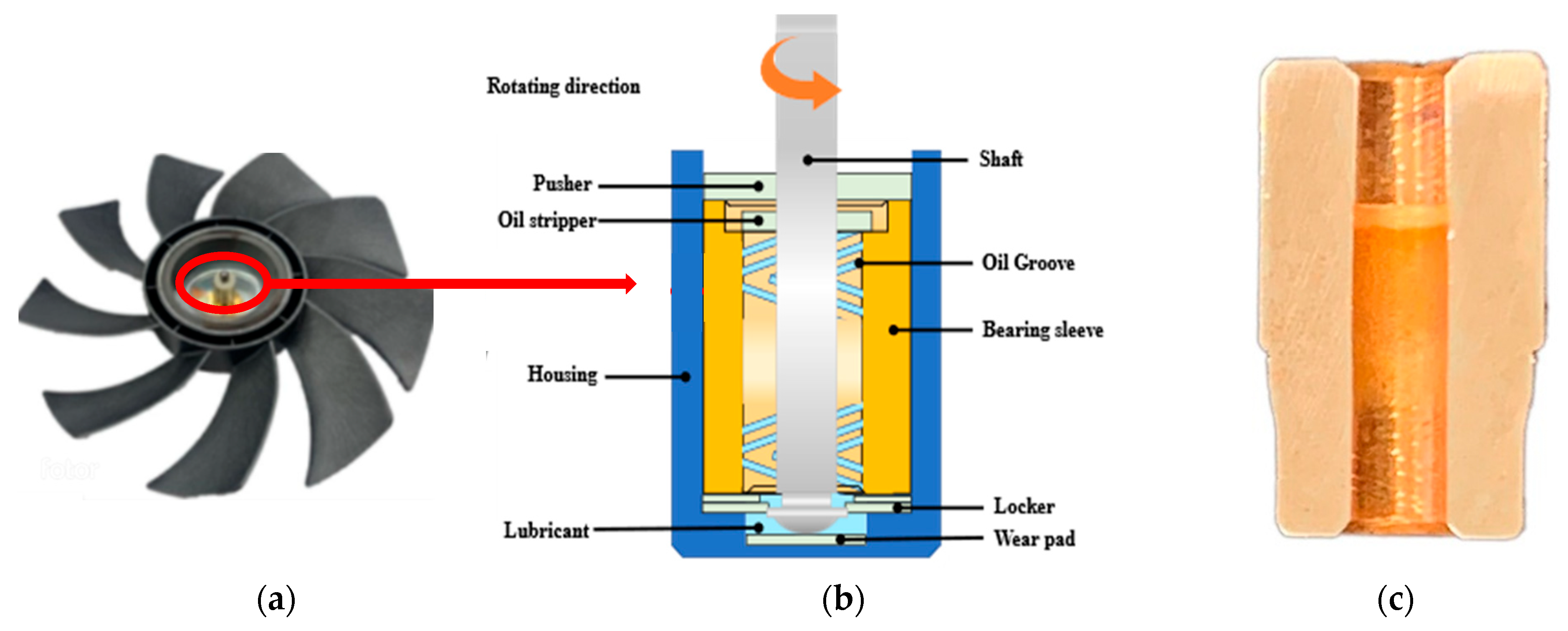
Figure 1. Physical and schematic diagrams of the powder metallurgy bearing: (a) fan, (b) bearing schematic diagram, and (c) bearing sleeve.
Lubricants 13 00245 g001
Figure 2. (a) Bearing cross-section region classification: (b) porosity distribution of each region, (c) OM image of the front region surface, (d) OM image of the middle region surface, and (e) OM image of the rear region surface.
Lubricants 13 00245 g002
Figure 3. Corrosion testing equipment: (a) physical photograph, (b) schematic diagram of the corrosion chamber, and (c) schematic diagram of the analysis computer.
Lubricants 13 00245 g003
Figure 4. Temperature and humidity control chamber.
Lubricants 13 00245 g004
Figure 5. Accelerometer on the fan.
Lubricants 13 00245 g005
Figure 6. Schematic diagram of infrared thermometer measurement points (A, B, C, D, E, F).
Lubricants 13 00245 g006
Figure 7. Oil groove of the fan bearing before operation: (a) OM image and (b) surface profile of the oil groove.
Lubricants 13 00245 g007
Figure 8. Elemental composition analysis of the new bearing: (a) SEM image and (b) EDS composition analysis.
Lubricants 13 00245 g008
Figure 9. Polarization curves of the bearing in 3.5% NaCl electrolyte solution under different testing conditions.
Lubricants 13 00245 g009
Figure 10. (a) OM image, (b) SEM image, and (c) wear track diagram of the bearing after 3 days of operation at 80 °C and 85% humidity.
Lubricants 13 00245 g010
Figure 11. (a) OM image, (b) SEM image, and (c) wear track diagram of the bearing after 8 days of operation at 80 °C and 85% humidity.
Lubricants 13 00245 g011
Figure 12. Surface composition of bearing after operating at 80 °C and 85% humidity for different durations: (a) EDS spectrum after 3 days, (b) EDS spectrum after 8 days, and (c) changes in the surface element composition percentage.
Lubricants 13 00245 g012aLubricants 13 00245 g012b
Figure 13. Changes in the (a) vibration RMS value and (b) average current consumption vs. the vibration RMS value during 20 days of operation for bearings under different levels of corrosion.
Lubricants 13 00245 g013
Figure 14. Wear debris particle distribution of 3 bearings with different degrees of corrosion after 20 days of operation at 45 °C and 60% RH: (a) 0 days, (b) 3 days, (c) 8 days, and (d) SEM image of wear debris particles after 3 days.
Lubricants 13 00245 g014
Figure 15. Temperature variations after 20 days of operation at 45 °C and 60% RH for 3 bearings with different degrees of corrosion: (a) end cap surface temperature variation of the new bearing and (b) differences in temperature at the center point of each bearing.
Lubricants 13 00245 g015
Table 1. Property of lubricant.
PropertyValue
Viscosity (cSt)40 °C155.8
100 °C14.5
Density (g/cm3)20 °C0.979
Table 2. Corrosion current under different testing conditions.
ConditionCorrosion Current (amp/cm2)
25 °C + 35% RH1.29 × 10−6
45 °C + 35% RH—3 days1.38 × 10−5
45 °C + 35% RH—8 days1.41 × 10−5
80 °C + 35% RH—3 days6.04 × 10−5
80 °C + 35% RH—8 days7.55 × 10−5
Table 3. Composition of wear particles.
ElementAtom.%
C75.90
O16.97
Cu7.14
Disclaimer/Publisher’s Note: The statements, opinions and data contained in all publications are solely those of the individual author(s) and contributor(s) and not of MDPI and/or the editor(s). MDPI and/or the editor(s) disclaim responsibility for any injury to people or property resulting from any ideas, methods, instructions or products referred to in the content.