Article

Dynamic Precision and Reliability of Multi-Link Linkages with Translational Pair Clearance

1
Swinburne College, Shandong University of Science and Technology, Jinan 250031, China
2
Intelligent Equipment College, Shandong University of Science and Technology, Taian 271000, China
*
Author to whom correspondence should be addressed.
Lubricants 2025, 13(6), 246; https://doi.org/10.3390/lubricants13060246
Submission received: 12 April 2025 / Revised: 22 May 2025 / Accepted: 26 May 2025 / Published: 29 May 2025

Abstract

This study investigates the dynamic behavior and reliability of planar multi-link linkages with clearance in translational pairs. Using the Lagrange multiplier method, a dynamic model that accounts for clearance effects is developed. Furthermore, a reliability model is established by combining the first-order second-moment method with the stress-strength interference theory. Numerical simulations were performed to evaluate the impact of varying clearance sizes and driving speeds on motion errors and system reliability. This study also explores the nonlinear dynamics of the end-effector. The results indicate that increased clearance and higher driving speeds lead to certain changes in motion errors and operational reliability. Phase diagrams and Poincaré maps reveal directional differences in dynamic stability: chaotic motion along the X-direction and periodic oscillations along the Y-direction. These findings provide valuable insights for optimizing mechanism design and enhancing operational reliability.

1. Introduction

With the continuous advancement of precision mechanical manufacturing, mechanical systems are evolving toward higher precision and reliability. In practical industrial applications, planar multi-link mechanisms are extensively employed across various engineering fields, including robotics, automation, and aerospace. However, due to machining tolerances and assembly errors, clearances in kinematic pairs are inevitable. These clearances lead to nonlinear behavior in the motion system, adversely affecting its reliability and overall performance. Among the different types of joints, translational pairs—often serving as the end-effectors of planar multi-link mechanisms—have a substantial impact on the system’s operational stability. While existing reliability studies have predominantly focused on revolute joints, research addressing the reliability of translational pairs remains sparse [1,2,3,4,5,6,7,8]. Specifically, the effects of translational pair clearances on dynamic performance and system stability have not been sufficiently explored, making it a critical area for investigation. Therefore, a detailed investigation into the dynamic response, nonlinear characteristics, and reliability of planar multi-link mechanisms with translational pair clearances is essential for optimizing their design and ensuring operational dependability.
In recent years, extensive research has been conducted on the kinetic behavior of articulated systems with clearances, particularly focusing on planar multi-bar linkages with revolute joint clearances and spatial parallel mechanisms. Chen et al. [9] developed a dynamic model for a six-bar linkage incorporating revolute joint clearances using the Lagrange multiplier method. The study analyzed the parametric dependencies of clearance magnitude and quantity on the global dynamic behavior of the system. Phase diagrams and Poincaré maps were employed to investigate the chaotic behavior of clearance joints. Bai et al. [10] formulated normal and tangential friction force models to analyze contact impacts in revolute joint clearances and, based on the Achard model, quantitatively characterized the wear characteristics of the clearance joints. Huang et al. [11] performed nonlinear dynamic analysis of a gear transmission model with revolute joint clearance, considering clearance size, the impact ratio, and time-varying mesh stiffness. The study examined the influence of clearance on meshing stiffness, load distribution factors, and nonlinear dynamic behavior. Muvengei et al. [12] integrated the LuGre friction law to model stick-slip phenomena in revolute joint clearances, rigorously investigating the dynamic responses of planar rigid multibody systems by analyzing nonlinear oscillations induced by friction-dependent contact transitions and energy dissipation mechanisms. Olyaei et al. [13] developed a Pyragas-based time-delayed feedback control strategy to mitigate contact losses in slider-crank mechanisms with revolute joint clearances, demonstrating enhanced dynamic stability through the suppression of clearance-induced nonlinear oscillations and impact energy dissipation. Li et al. [14] studied the dynamic characteristics of a multi-link hinge mechanism with three revolute joint clearances and further examined the acceleration behavior of the mechanism under varying operational conditions through experimental studies. Lin et al. [15] developed a dynamic precision reliability framework for mechanisms with revolute joint clearances based on strength-stress interference theory and examined how the quantity and magnitude of clearance parameters affect the reliability of planar multi-bar linkages. Marques et al. [16] proposed a novel methodology for modeling spatial revolute joints with radial and axial clearances, systematically evaluating the suitability of normal and tangential contact force formulations for representing contact-impact interactions in clearance joints. Isaac et al. [17] developed a three-dimensional finite element-based methodology to investigate the influence of clearances in spatial revolute joints on the dynamic response of mechanisms, establishing a rigorous framework for modeling nonlinear contact dynamics and multibody interactions under clearance-induced uncertainties. Bai et al. [18] analyzed a planar slider-crank kinematic chain with two revolute joint clearances, performing numerical simulations and experiments under varying clearance dimensions and rotational velocities. Their findings were validated through comparison with simulation results. Yang et al. [19] formulated a dynamic analytical framework for a spatial open-loop mechanism featuring multi-site revolute joint clearances, investigating the effects of clearance location and component structural flexibility on the dynamic behavior. Brutti et al. [20] proposed a nonlinear equivalent force model to characterize revolute joint clearances, rigorously analyzing their influence on the dynamic behavior of slider-crank mechanisms through a multibody framework that captures nonlinear coupling effects between clearance-induced impacts and inertial forces. Farahan et al. [21] developed a Lagrange multiplier-based dynamic model for planar four-bar mechanisms with revolute joint clearances, systematically investigating clearance-dependent dynamic response characteristics while considering nonlinear contact kinematics and constraint violation effects. Zhang et al. [22] constructed a wear model for a vector nozzle adjustment actuator system, incorporating revolute joint clearance, revealing that larger clearance values result in deeper wear.
Research on mechanisms with translational pair clearances has also attracted significant attention in recent years, especially for planar multi-bar linkages and simple spatial parallel mechanisms. Wu et al. [23] analyzed the dynamic motion of a double-crank linkage with translational pair clearance and studied the influence of actuation velocity as well as clearance value using ANSYS/LS-DYNA simulations. Jiang et al. [24] developed a dynamic analytical framework for a 2-DOF 9 bar linkage incorporating translational pair clearance and examined the effects of clearance magnitudes and operational velocities on the nonlinear characteristics through trajectory maps, phase diagrams, integral diagrams, and bifurcation diagrams. Wang et al. [25] proposed a dynamic model for a jaw crusher with translational pair clearance, employing the Lagrange multiplier method. The study investigated the interplay between operational velocities and clearance size on chaotic behavior, with the results validated through ADAMS simulations. Ahmedalbashir et al. [26] proposed a spring compensation strategy to mitigate clearance-induced disturbances in mechanisms, validated through numerical and experimental analyses. Results demonstrated that continuous journal–sleeve contact induced by a spring mechanism effectively reduced nonlinear oscillations and improved dynamic stability. Liu et al. [27] quantified the influence of joint component flexibility and gap lubrication on the dynamic behavior of planar mechanisms with translational pair clearance. Erkaya et al. [28] conducted experimental vibration measurements and numerical investigations on articulated mechanisms, analyzing clearance joint effects on dynamic response characteristics. The results demonstrated that clearance joints adversely affected the mechanism’s operational performance by inducing nonlinear oscillations and reducing kinematic accuracy. Zheng et al. [29] developed a modeling approach for planar mechanisms featuring translational pair clearance, addressing the uncertainty in static analysis and verifying the results through simulations. Dong et al. [30] proposed a dynamic model for a flexible rocker mechanism incorporating translational pair clearance, examining the effect of load and actuation velocity on dynamic behavior. Akhadkar et al. [31] developed a non-smooth dynamics framework for analyzing joint clearance effects in a 42-DOF circuit breaker mechanism. An event-capturing scheme with cone complementarity resolved multibody contacts efficiently, enabling Monte Carlo sensitivity analysis while maintaining experimental correlation despite minimal parameter dependence. Tan et al. [32] formulated a dynamic model for a crank-slider mechanism incorporating translational pair clearance, employing the Lagrange multiplier method. The study analyzed the effect of various types of clearance on the dynamic behavior of constrained systems.
Meanwhile, given the varying performance of mechanisms under diverse operating conditions, evaluating the reliability of such mechanisms assumes critical importance. Consequently, researchers have undertaken in-depth analyses and investigations into reliability. Jiang et al. [33] established a quantitative reliability model for planar multi-link systems with multiple clearances, revealing their synergistic effects. Xiang et al. [34] proposed a sensitivity analysis method for dynamic responses in four-bar mechanisms, incorporating clearance joints and parameter uncertainties. Gao et al. [35] constructed a rigid-body dynamic model for clearance-containing slider-crank mechanisms and quantified reliability sensitivity via Monte Carlo simulations. Chen et al. [36] formulated a reliability assessment framework for mechanical systems through first/second-moment analysis, conducting reliability evaluations on a lubricated 2-DOF 9-linkage system under cyclic clearance conditions. Zhan et al. [37] presented a probabilistic motion reliability framework for planar parallel manipulators considering clearance-induced kinematic deviations. Geng et al. [38] established a stochastic reliability model addressing clearance dimensional uncertainties, verifying predictions through numerical experiments. Zhang and Du [39] implemented an envelope function-based approach to compute motion reliability for four-bar linkages with revolute joint imperfections. Wu et al. [40] created a dry friction clearance reliability predictor for slider-crank systems. Li et al. [41] quantified motion reliability in Delta parallel robots via stress-strength interference modeling. Yang et al. [42] conducted reliability sensitivity studies on enhanced Delta mechanisms using response surface methodology, with Monte Carlo validation. Jia et al. [43] built a metamodel-based reliability predictor for 4-UPS/RPS spatial mechanisms, investigating clearance magnitude and actuation velocity effects. Zhan et al. [44] integrated first/second-moment theory with stochastic simulation for 3-RRR parallel robot reliability analysis.
In summary, previous research on mechanisms with clearances has primarily focused on the effects of clearance on dynamic responses, energy dissipation characteristics, and nonlinear behavior. However, studies addressing the reliability of mechanisms incorporating translational pairs remain relatively scarce. As a key kinematic pair, the translational pair often functions as the end-effector of a mechanism, playing a crucial role in its overall operational performance. Therefore, in this study, a comparative analysis was first conducted to examine the effects of translational and revolute joint clearances on the dynamics of multi-link mechanisms. The importance of studying translational joint clearance in ensuring the stable operation of the mechanism and maintaining machining accuracy was emphasized. In addition, the dynamic responses of multi-link mechanisms with clearance in revolute pairs under different material parameters, different clearance sizes, and driving conditions were analyzed. Meanwhile, systematic studies on the nonlinear characteristics and reliability were conducted. The findings provide valuable theoretical insights for the optimization and reliability assessment of such mechanisms.
The contributions of this research article are presented in the following sections: Section 2 establishes a dynamic model for mechanisms with translational pair clearance. Section 3 develops a reliability assessment methodology for a six-bar mechanism. Section 4 compares the effects of different types of single joint clearances on the dynamics of the six-bar mechanism. The influence of different material parameters, different clearance sizes, and driving speeds on the dynamic characteristics of a six-bar linkage with a translational pair is further investigated, with simulations conducted using ADAMS for validation. Additionally, the nonlinear behavior of the mechanism’s end-effector was analyzed to further elucidate its dynamic performance. Section 5 evaluates the reliability of the mechanism under varying clearance sizes and driving speeds. Section 6 shows the conclusions and summary of the findings.

2. Dynamic Model of Mechanisms with Translational Pair Clearance

2.1. Establishment of the Translational Pair Clearance Motion Model

The clearance model for the translational pair is depicted in Figure 1, where the internal component represents the slider, and the external component represents the guide rail. The separation between the inner surfaces of the guide rail is defined as H T , and the length, width, and thickness of the slider are denoted as L , W T , and T , respectively. The clearance value of the translational pair can be expressed as follows:
c T = H T W T 2
The analysis model of the translational pair clearance is depicted in Figure 2, where component m represents the slider and component n represents the guide rail. The slider is denoted as component m, and the guide rail is denoted as component n. o m and o n represent the mass centroids of the slider and guide rail, respectively. o m - x m y m and o n - x n y n are the local coordinate systems of the slider and guide rail, and O - XY is the global coordinate system.
Let H , I , G , and K be the geometric constraint points on the guide rail that may come into contact with the slider. A m , B m , C m , and D m are the four corner points of the slider, A n , B n , C n , and D n are the four corner points on the guide rail that are closest to the slider. The position equations for the corner points of the slider are similar; here, this paper takes point A as an example. For an arbitrary point H located on component i , the spatial coordinates can be formulated as follows:
r Hi = r i + A i s H i ( i = m , n )
where r i denotes the centroidal displacement vector of component i in the fixed coordinate system, A i denotes the transformation matrix, and s Hi denotes the displacement vector of any point H in the local coordinate system of component i .
The position vector between point A m on the slider and point A n on the guide rail is given by Equation (3). The normal vector of the guide rail surface is defined in Equation (4).
δ T = r A n r A m
n T = ( t T y t T x ) T
where t T x and t T y are the components of the tangent vector t T in the X and Y directions, respectively.
When the slider and guide rail collide, the vector δ T and the normal vector n T are collinear and point in opposite directions.
The collision criterion between the slider and the guide rail is described by Equation (5), while the normal vector of the guide rail surface is defined by Equation (6) [45].
n T T δ T < 0
δ T = δ T T δ T

2.1.1. Establishment of the Normal Collision Force Model

As shown in Figure 3a, when two adjacent corners of the slider collide with the guide rail, the collision force between the slider and the guide rail acts at the center of mass of the penetration region. The collision force is represented by the following:
F n = K δ T
Within the mathematical formulation, the stiffness coefficient is as follows [45]:
K = a 0.475 σ m + σ n
where a represents half the perimeter of the contact side of the slider rectangle, a = T + L , as shown in Figure 1. σ m = 1 μ m 2 E m , σ n = 1 μ n 2 E n , E m , and E n represents the elastic modulus, while μ m and μ n represents the Poisson’s ratio of the slider and the guide rail, respectively.
As shown in Figure 3b, when one or both of the opposite corners of the slider collide, the contact occurs between a spherical and a planar surface. The contact force model is as follows [46,47]:
F n = K δ T n + D δ ˙ T
In the formula, the stiffness coefficient is as follows:
K = 4 3 σ m + σ n R m n 1 2
here, R m n is the radius of curvature of the slider’s corner. The damping coefficient D is as follows:
D = 3 K ( 1 c e 2 ) δ T n 4 δ ˙ ( )

2.1.2. Formulation of the Tangential Friction Force Model

The modified Coulomb friction model addresses the numerical integration instability arising from the direction of the friction force near zero velocity [48,49]. The enhanced Coulomb-based frictional contact formulation is mathematically represented as follows:
F t = c f c d F n v t v t
where c f represents the friction coefficient, and c d serves as the restitution coefficient, defined by the following:
c d = 0 v t < v 0 v t v 0 v 1 v 0 v 0 < v t < v 1 1 v t > v 1
where v t is the relative sliding velocity, and v 0 denotes the maximum static friction speed. v 1 represents the transitional velocity for kinetic friction.

2.2. Dynamic Model of Mechanisms with Translational Pairs

2.2.1. Structural Characteristics of the Press Mechanism’s Linkage System

The mechanism shown in Figure 4 consists of the frame, crank 1 ( L 1 ), connecting rod 2 ( L 2 ), rocker 3 ( L 3 ), connecting rod 4 ( L 4 ), and slider 5. Crank 1, powered by an electric motor, actuates slider 5 to undergo reciprocating displacement through rail guidance.
The six-bar linkage analyzed in this study demonstrates favorable kinematic characteristics.

2.2.2. Dynamic Model of the Six-Bar Linkage Considering the Clearance of Translational Pairs

Figure 4 schematically depicts the coordinate configuration of the six-bar linkage. Each component in the mechanism can be represented by generalized coordinates as follows:
q i = x i y i θ i T i = 1 , 2 , 3 , 4 , 5
In the equations, x i and y i denote the positional components of the link in the x- and y-directions of the global reference frame, respectively, while θ i denotes the orientation angle of the component i .
The generalized coordinates can be aggregated as follows:
q = q 1 q 2 q 3 q 4 q 5 T
When clearance exists in the translational pairs, the displacement constraint equation is formulated as follows:
Φ q , t = x 1 L s 1 c o s θ 1 y 1 L s 1 s i n θ 1 x 2 L s 2 c o s θ 2 x 1 L s 1 c o s θ 1 y 2 L s 2 s i n θ 2 y 1 L s 1 s i n θ 1 x 3 L s 3 c o s θ 3 H x y 3 L s 3 s i n θ 3 H y x 3 x 2 L s 3 c o s θ 3 y 3 y 2 L s 3 s i n θ 3 x 4 L s 4 c o s θ 4 x 3 L s 3 c o s θ 3 y 4 L s 4 s i n θ 4 y 3 L s 3 c o s θ 3 x 5 x 4 L s 4 c o s θ 4 y 5 y 4 L s 4 c o s θ 4 θ 1 ω 2 t 111.36 o = 0
In this study, the upper dead point of the slider is selected as the initial position, where 111.36° is the angle between the crank and the horizontal line measured at the initial position. By differentiating Equation (16) with respect to time, we derive the velocity constraint equation of the system, which accounts for the clearance in the translational pairs:
Φ q q ˙ = Φ t v
where Φ q is the Jacobian matrix of the constraint equation, Φ q = δ Φ δ q , and q ˙ is the generalized velocity vector, Φ t = δ Φ δ t .
The Jacobian matrix of the mechanism Φ q is given as follows:
Φ q = ( Φ q 1 , Φ q 2 , Φ q 3 , , Φ q 13 , Φ q 14 , Φ q 15 )
By differentiating Equation (17) with respect to time, we derive the acceleration constraint equation:
Φ q q ¨ = ( Φ q q ˙ ) q q ˙ 2 Φ q t q ˙ Φ t t γ
where q ¨ represents the generalized acceleration vector of the system, Φ q t = 0 13 × 15 , Φ t t = 0 13 × 1 .
The dynamic equation of the system is given as follows:
M q ¨ + Φ q T λ = g
In the equation, M characterizes the system’s mass matrix, λ characterizes the Lagrange multipliers, and g characterizes the generalized force.
The kinematic state term system is integrated into the dynamic constraint equation by using the Baumgarte stabilization method, effectively enhancing the solution stability. This technique improves the stability of the solution. The improved dynamic equation of the system is as follows [50]:
M Φ q T Φ q 0 q ¨ λ = g γ 2 α Φ ˙ β 2 Φ
where α and β are positive correction parameters, Φ ˙ = d Φ d t .

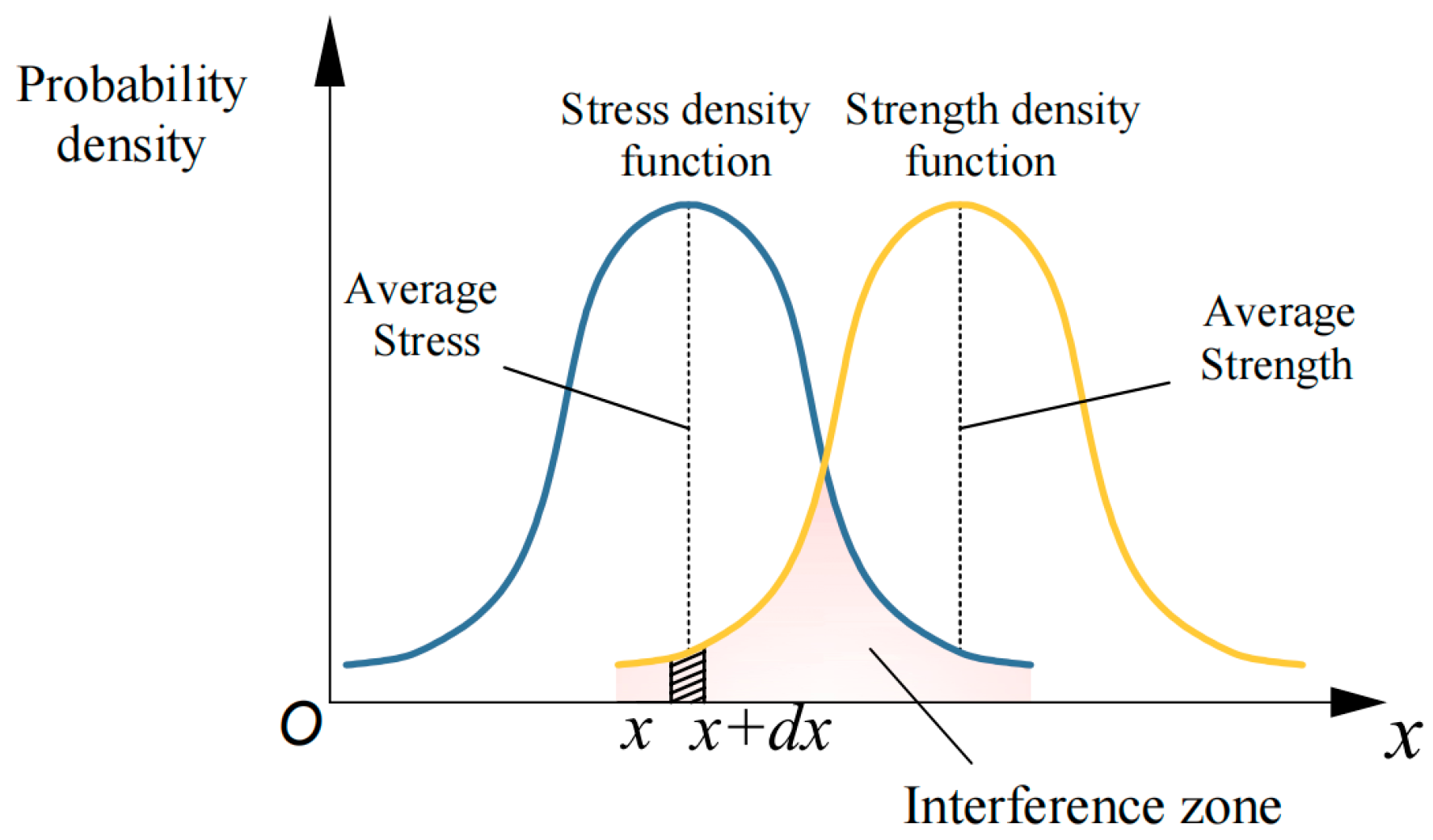
3. Reliability Model Development

3.1. Kinematic Fidelity Reliability Analysis for Planar Multi-Link Systems with Joint Clearances

3.1.1. First-Order Second-Moment Method

The dynamic model presented above offers a quantitative characterization of motion errors in systems with translational pair clearances. However, for practical engineering applications, it is crucial to evaluate the long-term effects of such errors on the reliability of the mechanism. To address this, the present section combines the first-order second-moment (FOSM) method with stress–strength interference theory to develop a dynamic accuracy reliability model. This model is used to quantitatively analyze the influence of different parameter changes on the reliability of the system. The first-order second-moment (FOSM) method provides significant computational efficiency and precision, making it indispensable for assessing the reliability of mechanism motion accuracy [51,52]. This approach quantifies reliability characteristics under various parameter configurations by utilizing mean values and standard deviations as statistical measures, thereby offering a robust quantitative foundation for reliability analysis. In practical applications, factors such as dimensional errors from manufacturing, joint clearances, and processing accuracy can significantly impact the mechanism’s performance. Additionally, manufacturing errors exhibit randomness, leading to stochastic variations in the mechanism’s motion parameters. Let the random variables influencing the kinematic behavior of the mechanism be denoted as X i ( i = 1 , 2 , 3 , n ) , where each variable follows an independent normal distribution. The functional equation of the mechanism is as follows:
Z i = g ( X 1 , X 2 , X 3 X n )
The limit state equation is mathematically defined as follows:
Z i = g ( X i ) = 0
Assuming that the functional equation of the mechanism is linear, it becomes the following:
Z i = a 1 X 1 + a 2 X 2 + a 3 X 3 + a n X n = 0
where a 1 , a 2 , a 3 a n are constants. The mean μ z i and standard deviation σ z i of the functional equation are expressed as follows:
μ z i = i = 1 n a i μ x i
σ z i = i = 1 n a i 2 μ i 2
By applying the FOSM method, the reliability index for planar mechanisms subjected to multifactorial influences is mathematically expressed as follows:
β 0 = μ z i σ z i = i = 1 n a i μ x i i = 1 n a i 2 μ i 2
Given that the actual distribution of the mechanism’s output error and the tolerance limits established in engineering applications adhere to a normal distribution, the stress-strength interference theory facilitates an efficient evaluation of motion precision reliability. The computational framework is graphically detailed in Figure 5. Since the stress and strength are stochastic, both exhibit variability.
As shown in Figure 5, even when the mean strength exceeds the mean stress, an “interference region” may exist where the strength is lower than the stress. Reliability is quantified as the probability that strength exceeds stress:
R = P ( S s > 0 ) = P ( Z > 0 )
Here, S represents strength, s represents stress, and Z = S s denotes the safety margin. The safety margin Z determines whether the mechanical system functions properly. If the strength exceeds the stress, i.e., Z < 0 , the mechanical system is operating normally; otherwise, it fails. Assuming stress and strength follow normal distributions, the safety margin also follows to a normal distribution.
f ( Z ( S , s ) ) = 1 2 π σ Z e 1 2 Z μ Z σ Z 2
Here, μ S and μ s represent the mean values of strength and stress, respectively, while σ S and σ s represent the standard deviations of strength and stress, respectively, μ Z = μ S μ s , σ Z = σ S 2 + σ s 2 .
The reliability, or the probability that the safety margin Z > 0 , can be formulated as follows:
R = P Z S , s > 0 = 0 1 2 π σ Z e 1 2 Z μ Z σ Z 2 d z
Transform into the standard normal distribution form as follows:
R = 0 f Z d Z = z 0 φ z d z = φ z 0
In the equation, φ z = 1 2 π e 1 2 z 2 , z = Z μ Z σ Z , z 0 = μ Z σ Z = μ S μ s σ S 2 + σ s 2 .
The reliability index β 1 is defined as follows:
β 1 = μ z σ z = μ S μ s σ S 2 + σ s 2
Thus, the reliability calculation formula is:
R = 0 f Z d Z = Φ β 1

3.1.2. Dynamic Accuracy Reliability Model of Mechanisms

Define the operational duration of the system as ( t 0 , t 1 ) , and the error function is as follows:
g ( x , t ) = P P
where P and P denote the actual and ideal positions of the slider, respectively. Define the error limit as ε . When the g ( x , t ) ε , the system is considered reliable; otherwise, it fails.
In the context of the operational dependability of the mechanism investigated herein, stress corresponds to the actual positional deviation of the slider, whereas strength indicates the allowable tolerance. Assuming errors in slider displacement, velocity, and acceleration during operation conform to Gaussian distributions, the time-dependent precision reliability under diverse clearance magnitudes and operational velocities can be quantified via the stress-strength interference framework.
Using displacement reliability for illustration, the reliability index for displacement at time ( t 0 , t 1 ) is formulated as follows:
β S = μ z σ z = μ S 1 μ s 1 σ S 1 2 + σ s 1 2
where μ S 1 and σ S 1 denote the mean and standard deviation of the permissible displacement error, while μ s 1 and σ s 1 are the mean and standard deviation of the actual displacement error, respectively.
The mean of the permissible displacement error μ S 1 and the standard deviation of the permissible displacement error σ S 1 can be derived using the established rigid body dynamics model, with these parameters expressed as follows:
μ S 1 = Δ μ + Δ v 2 σ S 1 = Δ μ Δ v 6
In the equation, Δ μ and Δ v represent the upper and lower bounds of the required error, respectively.
The mechanism’s overall reliability is subsequently quantified as follows:
R = Φ β S

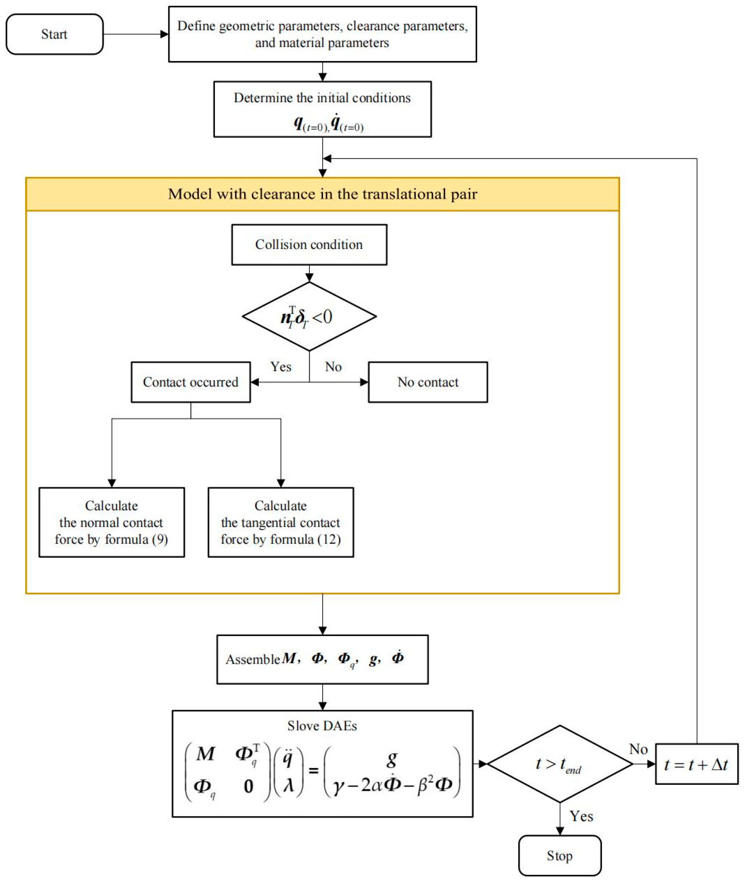
4. Analysis of the Dynamic Behavior and Nonlinear Features Incorporating Clearances in Rigid Body Systems

4.1. Simulation Parameters and Simulation Process

The mass, moment of inertia, and geometric parameters for each component are provided in Table 1. The specific parameters regarding the clearance of the translational joint are outlined in Table 2. Numerical simulations were performed using the MATLAB 2019 platform, utilizing its built-in stiff ordinary differential equation solver, ode15s, to address multi-body dynamics problems. The algorithm was developed and implemented via MATLAB scripts, with computations executed on an i7-10870H CPU for solving the dynamic equations. The workflow is illustrated in Figure 6.

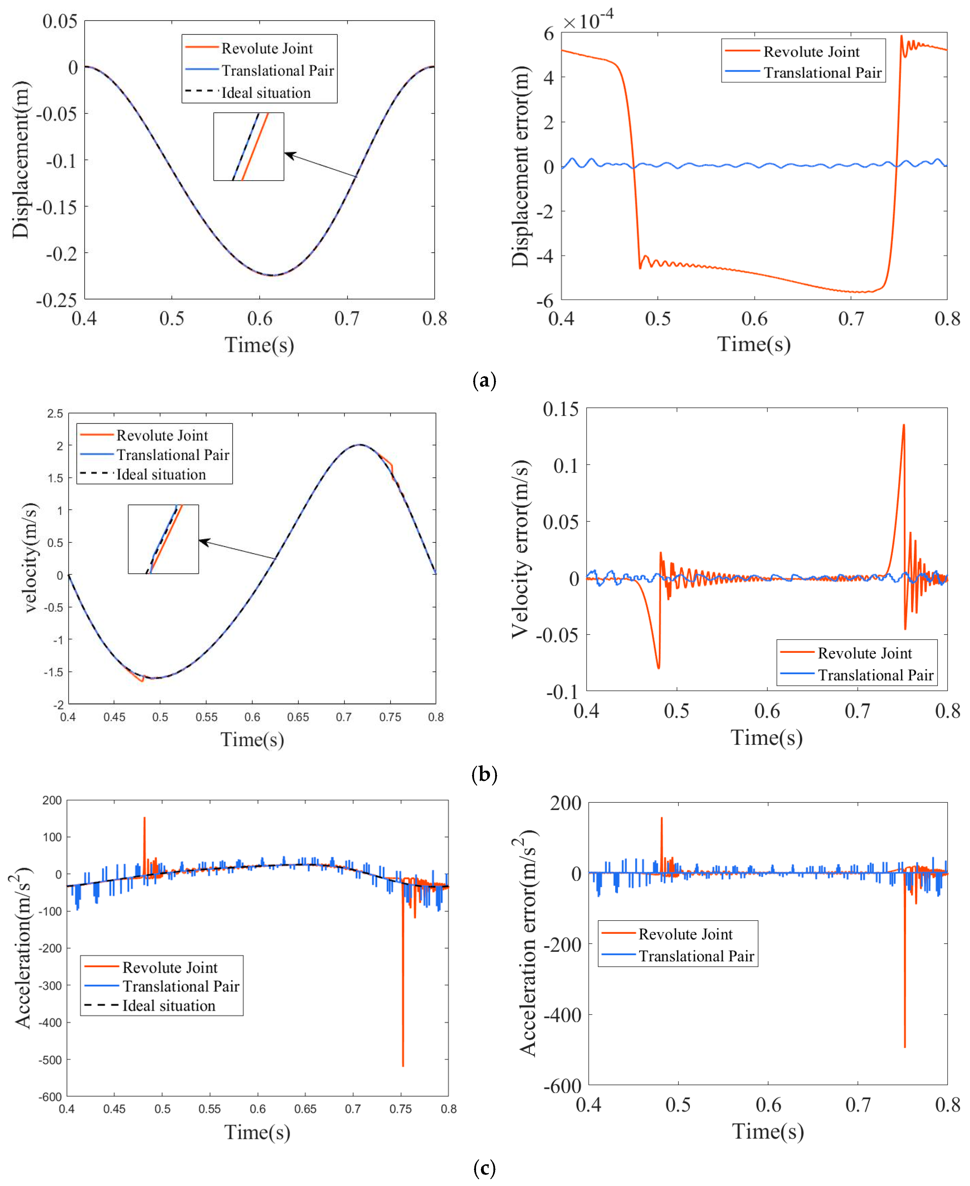
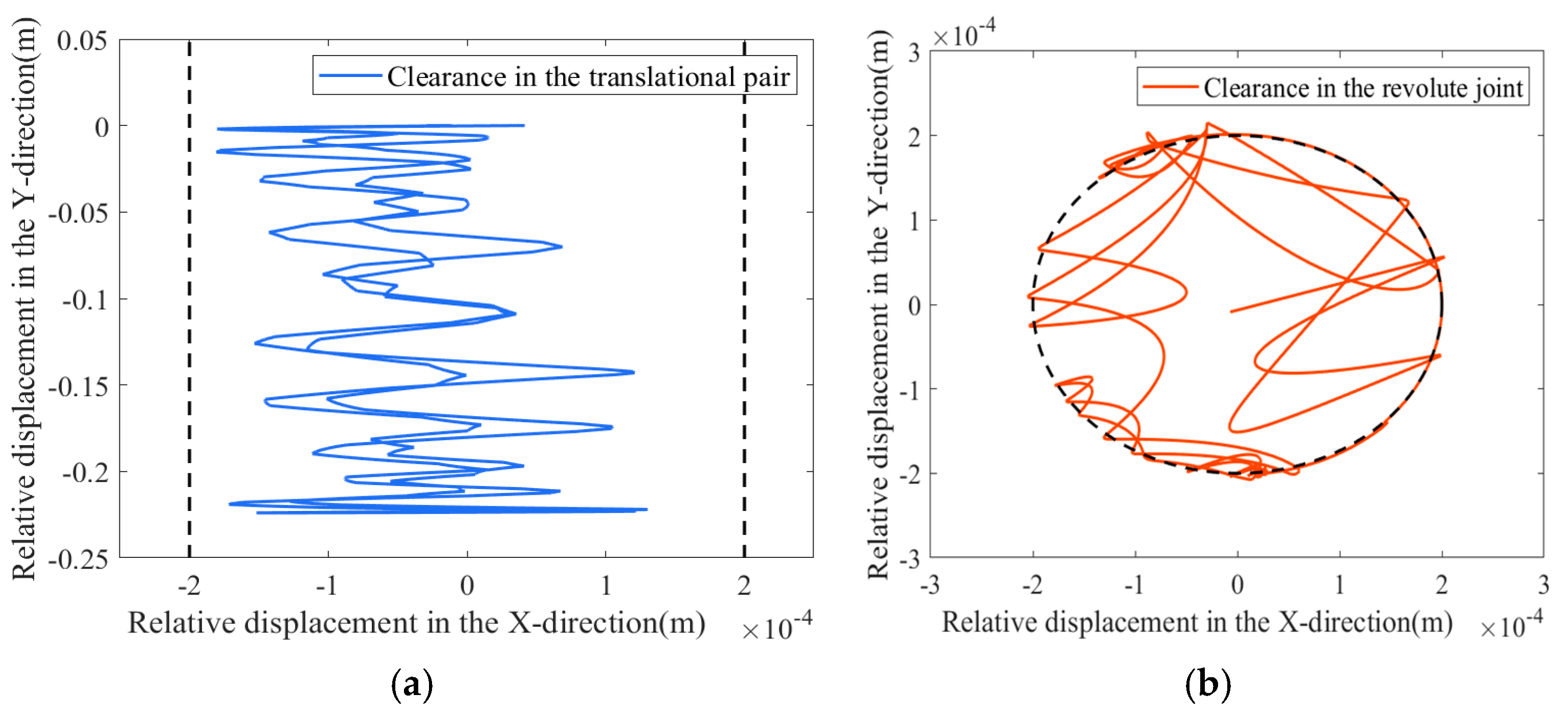
4.2. The Impact of Different Types of Single Joint Clearances on the Mechanism

To explore the influence of different types of single joint clearances on the mechanism, a dynamic analysis was performed under conditions where the driving speed was 150 rpm and the clearance value was 0.2 mm. Various types of single joint clearance were considered, as depicted in Figure 7, where the ideal situation in the figure refers to the dynamic response without including the clearance of the translational pair and revolute joint. Additionally, the directions of displacement, velocity, and acceleration align with the direction of the slider’s motion. Since the crank is directly driven by the motor, the translational pair clearance is associated with the slider. Consequently, the selected single clearances include the translational pair clearance at point F and the revolute joint clearance at point A, as shown in Figure 4. The clearances at points A and F effectively illustrate the impact of single joint clearances on the mechanism’s dynamics. The central trajectories of both the translational pair and the revolute joint during motion are presented in Figure 8.
As illustrated in Figure 7, when only the translational pair clearance is present, the peak values of displacement, velocity, and acceleration are 0.4112 × 10⁻⁵ m, −0.007544 m/s, and −68.24 m/s2, respectively. These peaks occur at 0.4112 s, 0.4141 s, and 0.4112 s, respectively. When only the revolute joint clearance is present, the peak values of displacement, velocity, and acceleration are 5.886 × 10⁻⁴ m, 0.1358 m/s, and −494.9 m/s2, with the peaks occurring at 0.7523 s, 0.7514 s, and 0.7522 s, respectively. Furthermore, as illustrated in Figure 8, the central trajectories of both the translational and revolute joint clearances exhibit evident randomness and uncertainty. When a clearance exists in the translational pair, the center trajectory demonstrates frequent oscillations. This behavior is primarily attributed to the significant angular deviation between the applied driving force and the resultant impact force on the slider, which induces high-frequency impact responses. These dynamic effects are clearly manifested as abrupt fluctuations in acceleration, as depicted in Figure 7c, under translational pair clearance conditions. In contrast, when a clearance is present in the revolute joint, the impact events within the central trajectory are primarily localized in the upper-left and lower-left regions. Consequently, the collision forces are predominantly concentrated in these two zones, which is reflected by the sharp variations in acceleration, specifically observed within these regions in Figure 7c.
Since the six-bar mechanism studied in this paper is a type of multi-link press, during actual operation, the contact position between the end effector and the workpiece occurs near the lowest displacement point of −0.224 m, at approximately 0.6166 s. During this operational phase, the displacement and velocity exhibited by different types of clearances are close to the ideal values. However, when only the translational pair clearance is present, the acceleration in this phase exhibits frequent abrupt changes, which could impact the machining quality of the workpiece during actual production. Therefore, further analysis and investigation are conducted specifically on the translational pair clearance.

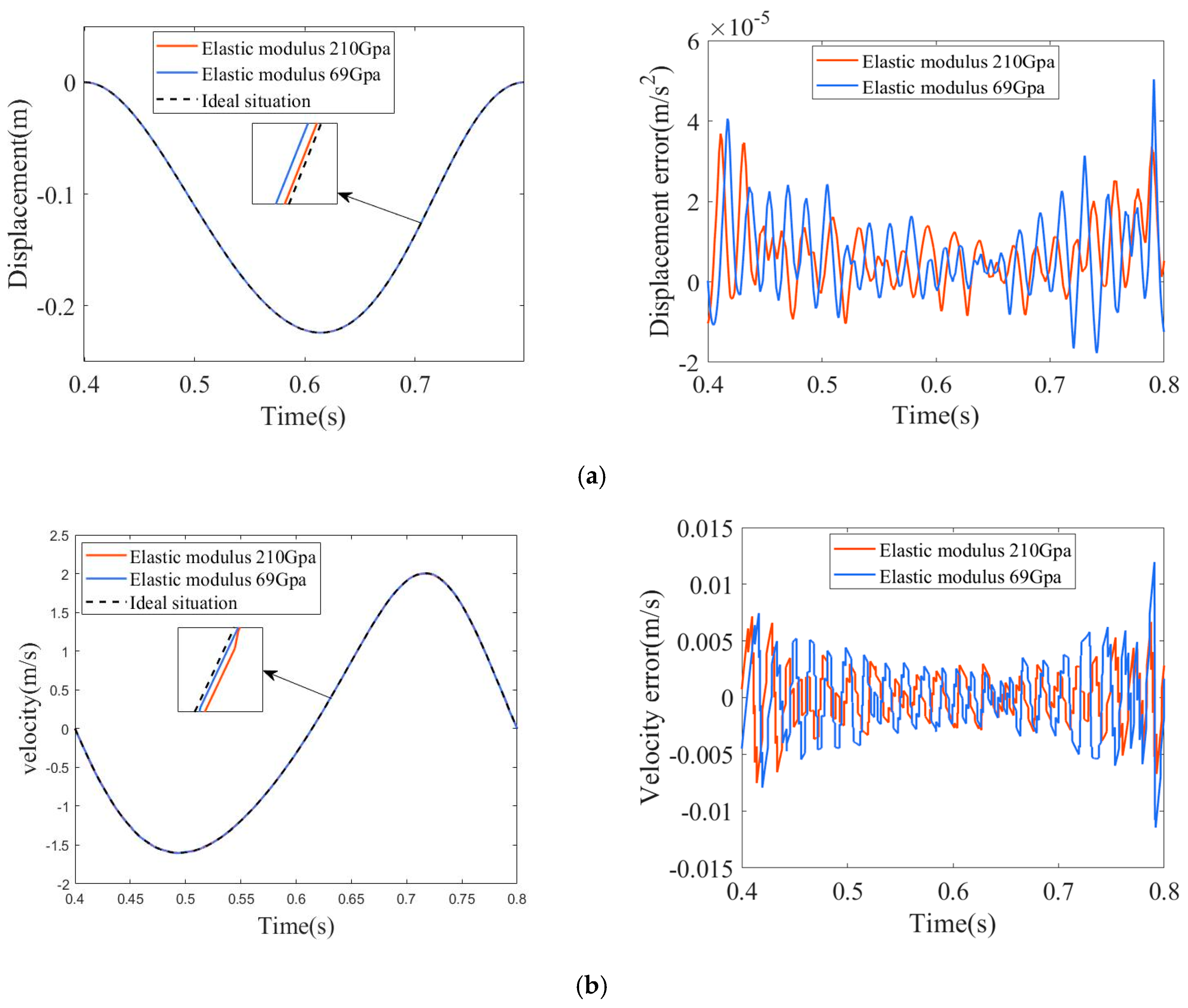
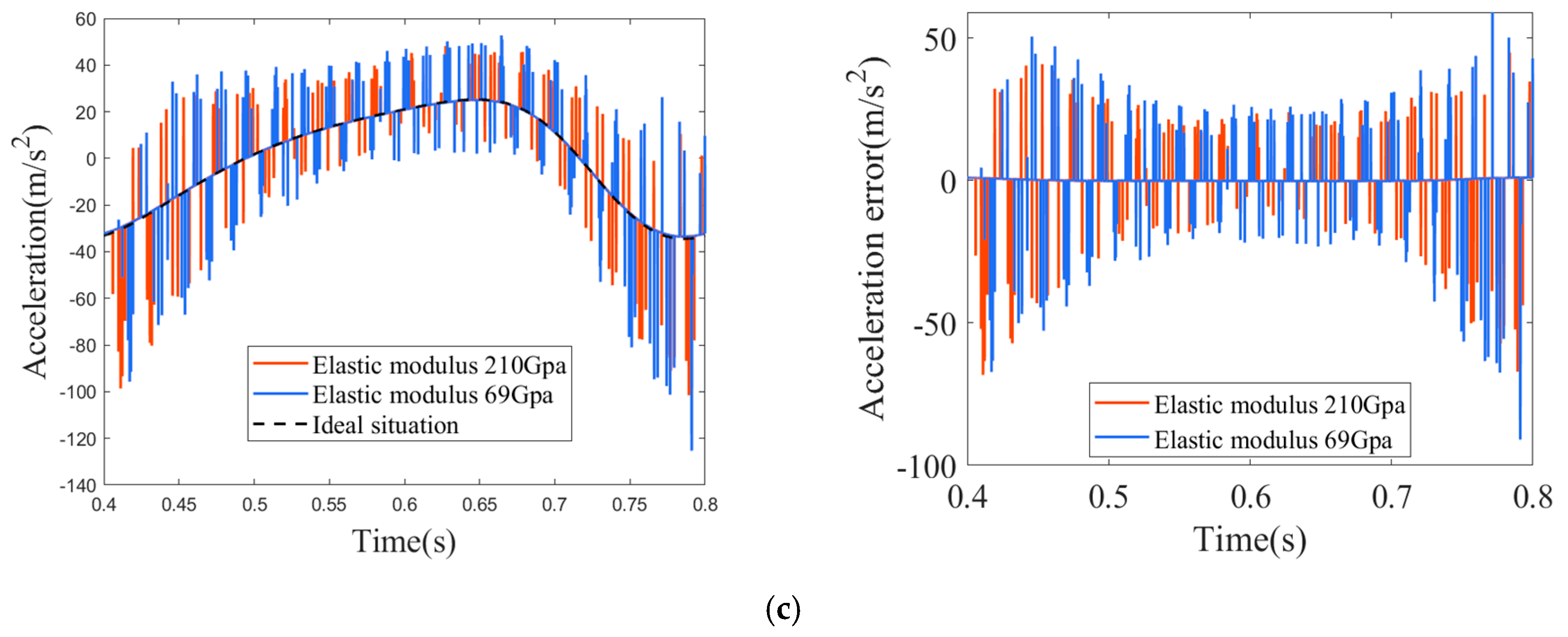
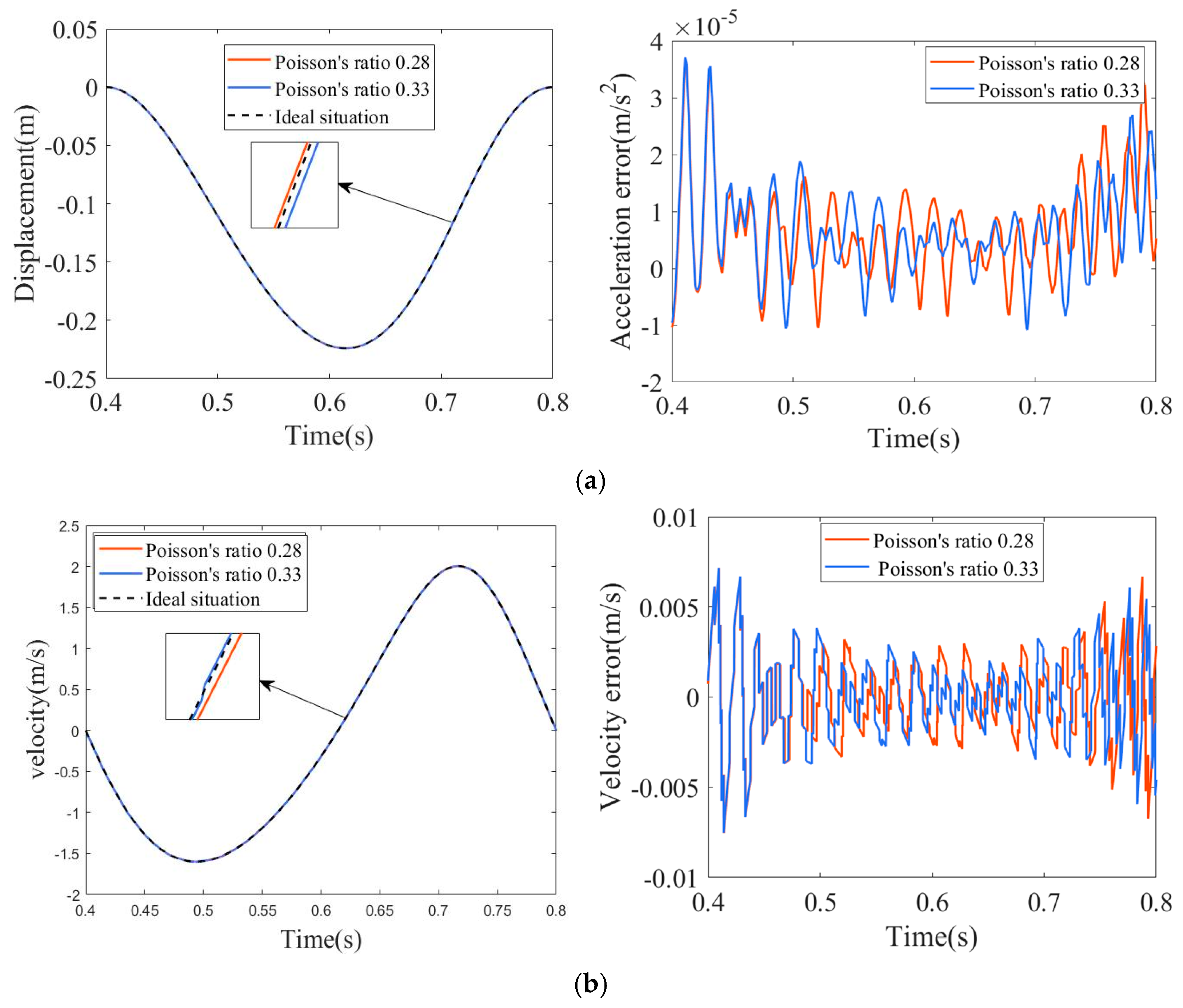
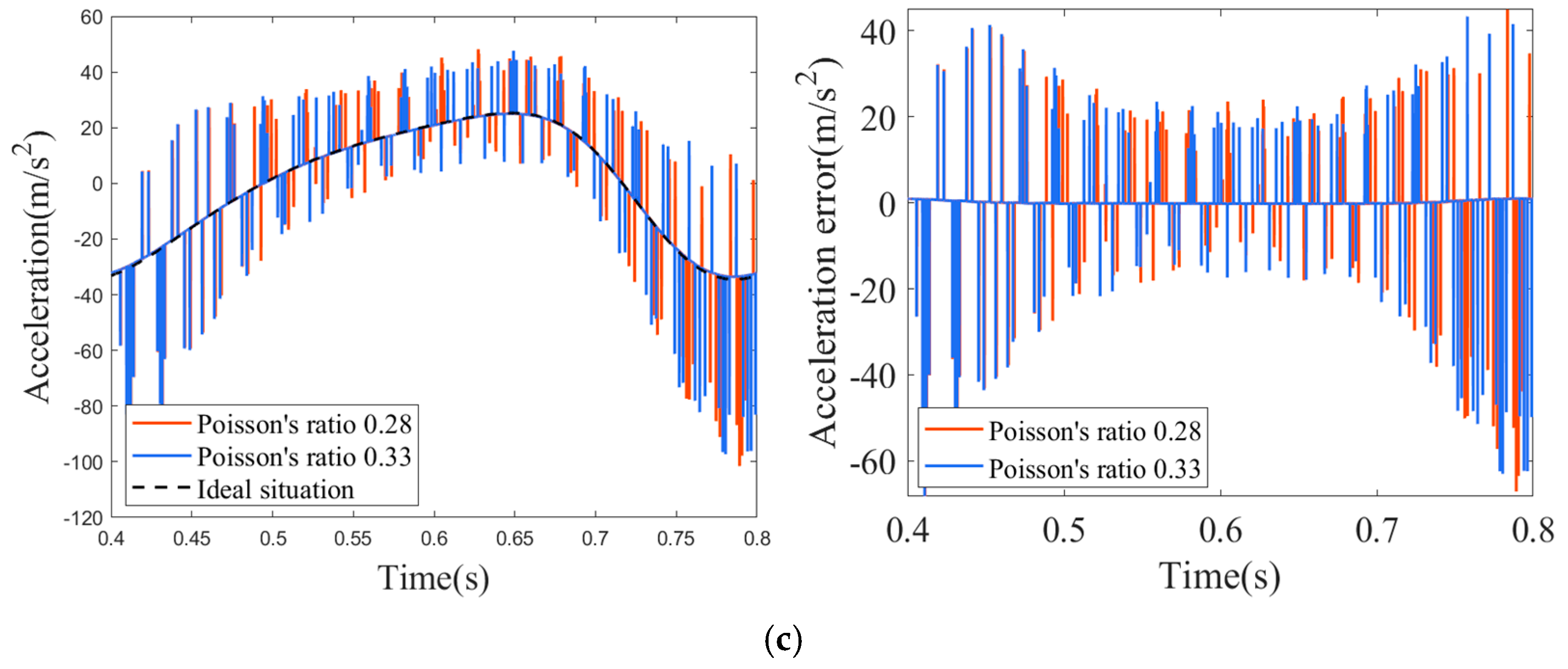
4.3. The Influence of Varying Material Parameters on Dynamic Performance

Under operating conditions defined by a driving speed of 150 rpm and a translational pair clearance of 0.2 mm, this study investigates the influence of material properties on the dynamic performance of a six-bar mechanism with clearance. For this purpose, two commonly used engineering materials—carbon steel and aluminum alloy—were selected for comparative dynamic analysis. The elastic modulus and Poisson’s ratio of carbon steel are 210 GPa and 0.28, respectively, while those of aluminum alloy are 69 GPa and 0.33. The slider’s dynamic response under varying elastic modulus values is illustrated in Figure 9, whereas the corresponding response for different Poisson’s ratios is presented in Figure 10.
The dynamic response of the slider under elastic modulus of 210 GPa and 69 GPa is presented in Figure 9. As shown in Figure 9a, the displacement error reaches peak values of 3.687 × 10⁻⁵ m at 0.4112 s and 4.993 × 10⁻⁵ m at 0.7909 s. Figure 9b depicts the velocity error, with corresponding peaks of −0.007544 m/s at 0.4141 s and 0.011840 m/s at 0.7906 s. The acceleration error, illustrated in Figure 9c, reaches maximum values of 68.24 m/s2 at 0.4110 s and −90.96 m/s2 at 0.7911 s. These results clearly demonstrate that a lower elastic modulus leads to larger displacement, velocity, and acceleration errors. This can be attributed to the increased susceptibility of low-stiffness materials to localized deformation at the contact interfaces. As a result, the slider fabricated from a softer material is more prone to frequent impacts and rebounds within the guideway clearance, which amplifies the dynamic response errors.
The dynamic response of the slider under Poisson’s ratios of 0.28 and 0.33 is illustrated in Figure 10. As shown in Figure 10a, the displacement error reaches peak values of 3.687 × 10⁻⁵ m at 0.4112 s and 3.687 × 10⁻⁵ m at 0.4110 s. The velocity response, depicted in Figure 10b, exhibits peak errors of −0.007544 m/s at 0.4141 s and −0.007526 m/s at 0.4139 s. As illustrated in Figure 10c, the acceleration error reaches peak values of −68.24 m/s2 at 0.4141 s and −68.22 m/s2 at 0.4139 s. These results indicate that the differences in peak errors under varying Poisson’s ratios are minimal, suggesting that Poisson’s ratio has a relatively insignificant effect on the dynamic response of the slider.

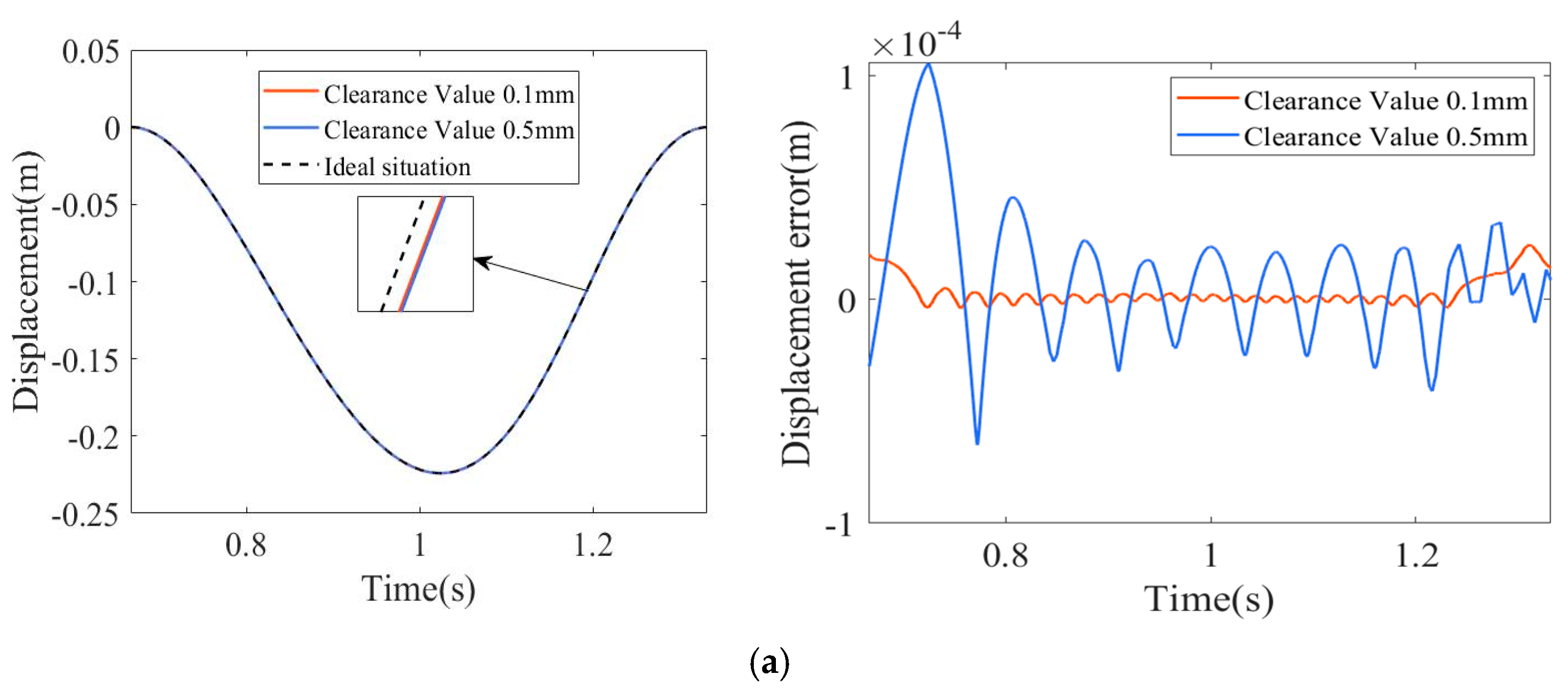
4.4. Impact of Clearance Magnitude on Dynamic Behavior

Figure 11 presents an analysis of the dynamic behavior of a six-bar linkage as the clearance in the translational pair is varied. With the crank rotating at a constant speed of 90 rpm, systematic variations in clearance were introduced to evaluate the resulting errors in slider displacement, velocity, and acceleration.
The displacement responses of the slider under clearance values of 0.1 mm and 0.5 mm are presented in Figure 11a. The corresponding peak displacement errors occur at 1.3110 s and 0.7228 s, with magnitudes of 2.468 × 10⁻⁵ m and 1.046 × 10⁻⁴ m, respectively. As shown in Figure 11b, the peak velocity errors appear at 0.7610 s and 0.7747 s, reaching 0.001085 m/s and 0.006153 m/s, respectively. In Figure 11c, the peak acceleration errors are observed at 0.7558 s and 0.7723 s, with values of 7.19 m/s2 and 31.38 m/s2. These results clearly indicate that increasing the clearance size leads to larger displacement, velocity, and acceleration errors, thereby exacerbating the dynamic instability of the mechanism.

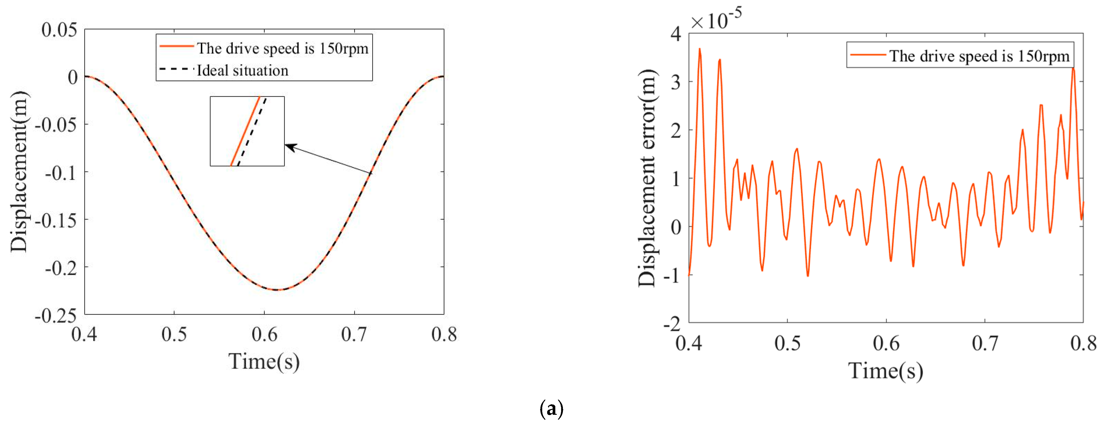
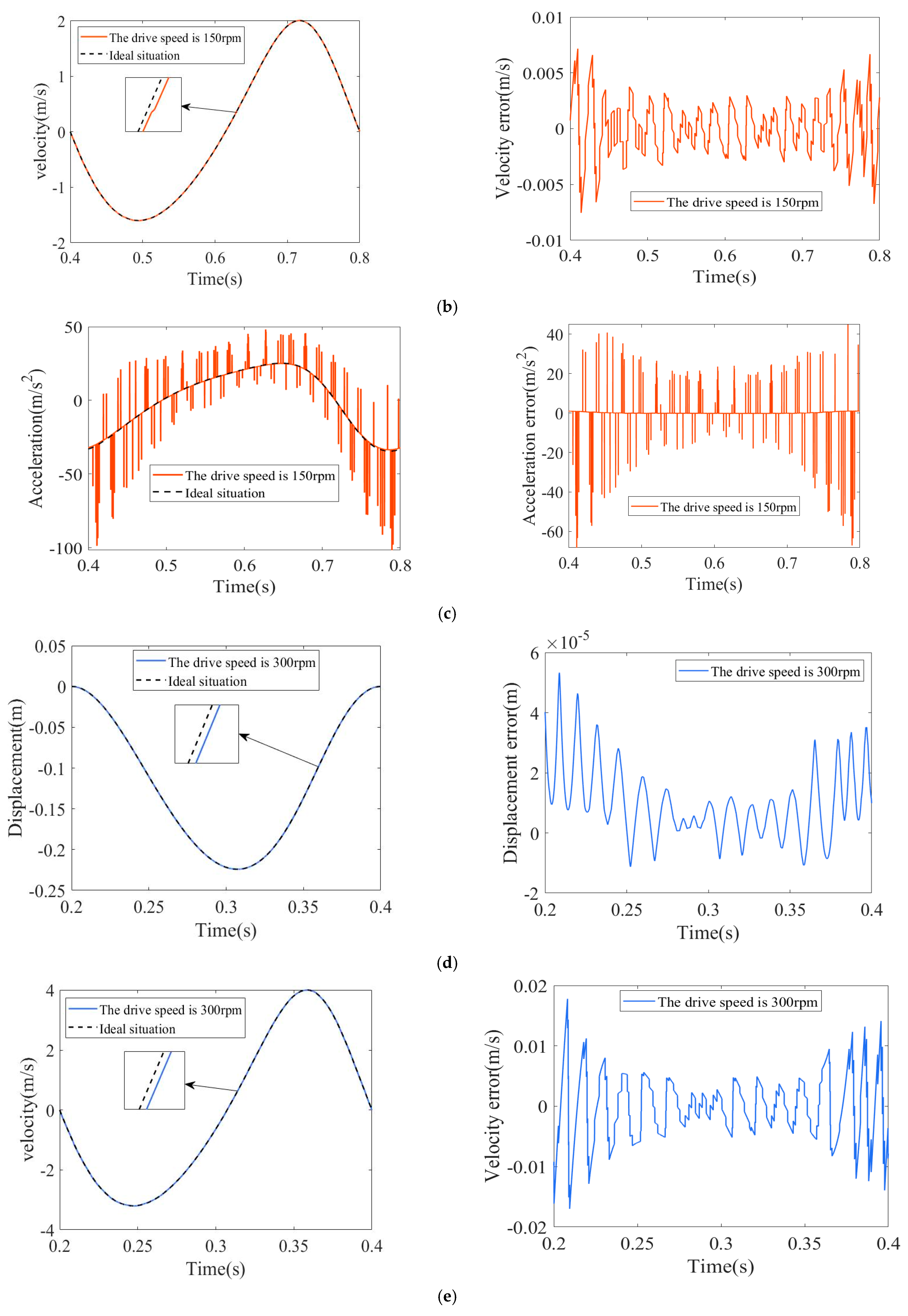
4.5. The Impact of Different Driving Speeds on the Dynamic Response of Rigid Body Mechanisms with Clearances

Figure 12 presents an analysis of the rigid-body dynamic behavior of the six-bar linkage system subjected to incremental crank angular velocities. With a constant 0.2 mm clearance in the translational pair, the study examines how variations in driving speed influence the error magnitudes in the slider’s motion parameters.
Figure 12a,d illustrate that at crank speeds of 150 rpm and 300 rpm, the maximum displacement errors occurred at 0.4112 s and 0.2088 s, with values of 3.687 × 10⁻⁵ m and 5.332 × 10⁻⁵ m, respectively. Figure 12b,e show that the peak velocity errors were detected at 0.4141 s and 0.2082 s, registering −0.007544 m/s and 0.0178 m/s, respectively. Figure 12c,f show that the highest acceleration errors were −68.24 m/s2 and −287.3 m/s2, occurring at 0.4112 s and 0.2088 s, respectively. The results clearly indicate that higher driving speeds amplify motion errors and compromise kinematic stability.
Simultaneously, in the dynamic analysis of the mechanism under varying clearances and driving speeds, the error values exhibit oscillatory behavior within each cycle. This phenomenon arises because the clearance induces collisions of varying intensities between the slider and the guide rail. Each collision generates an instantaneous impact force, which recurs periodically at either the driving frequency or the clearance closure frequency, thereby inducing forced vibrations.

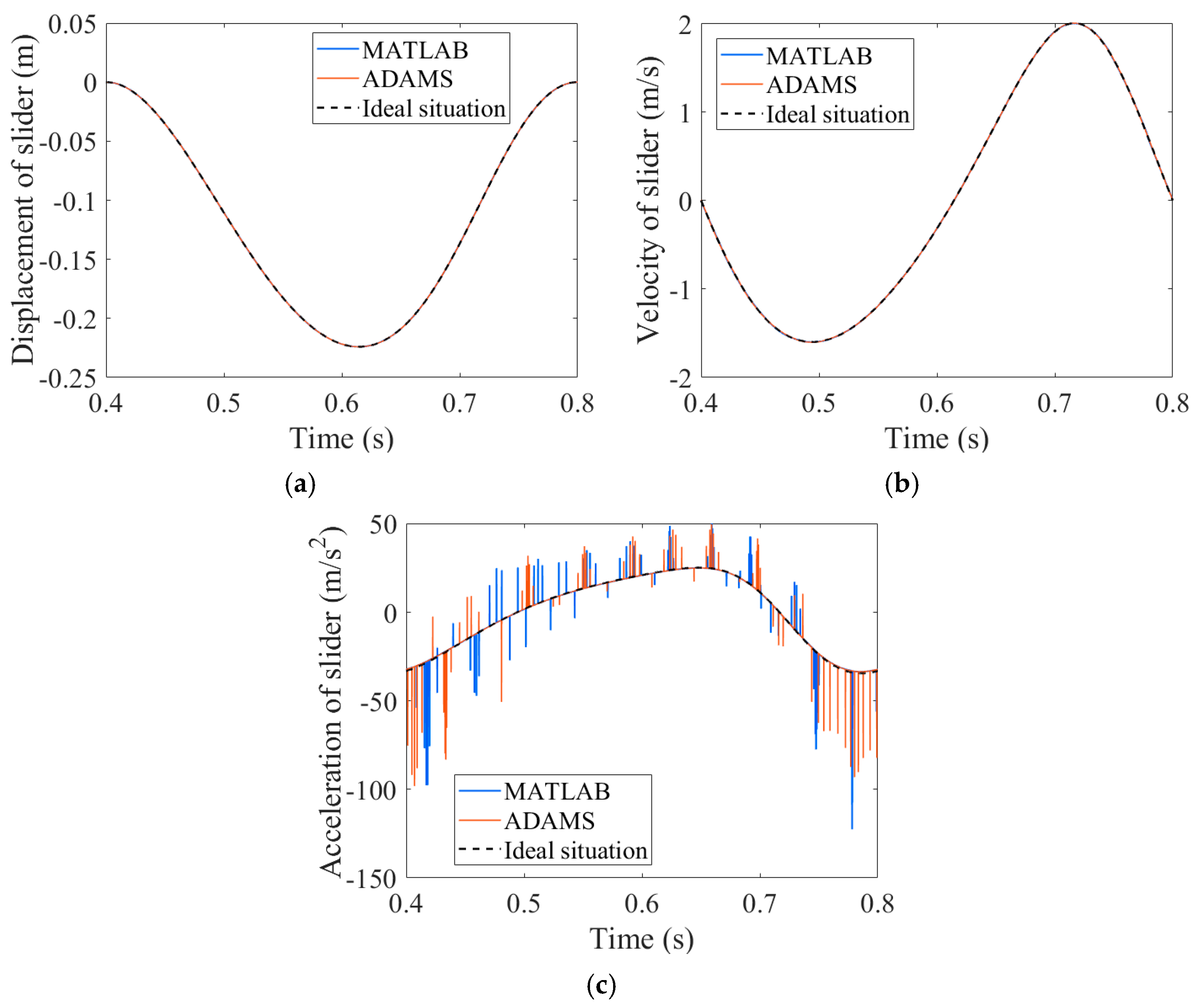
4.6. Virtual Prototype Model of a Mechanism with Translational Pair Clearance

To validate the accuracy of the model and data, the SolidWorks 2022 model of the six-bar mechanism was imported into ADAMS for simulation verification. Figure 13 shows the comparison chart of MATLAB and ADAMS results.
By comparing the results, it can be observed that the trends of the MATLAB and ADAMS result curves are generally consistent. However, the slight deviation observed in the acceleration curve arises from discrepancies between the theoretical calculation model and the virtual simulation model, particularly in their respective modeling and solution methodologies. Furthermore, factors such as step size control and error tolerance, among others, collectively affect the precision in capturing high-frequency impact responses. The correctness and rationality of the model can be largely verified by comparing the simulation results from ADAMS with the numerical analysis results from the model.

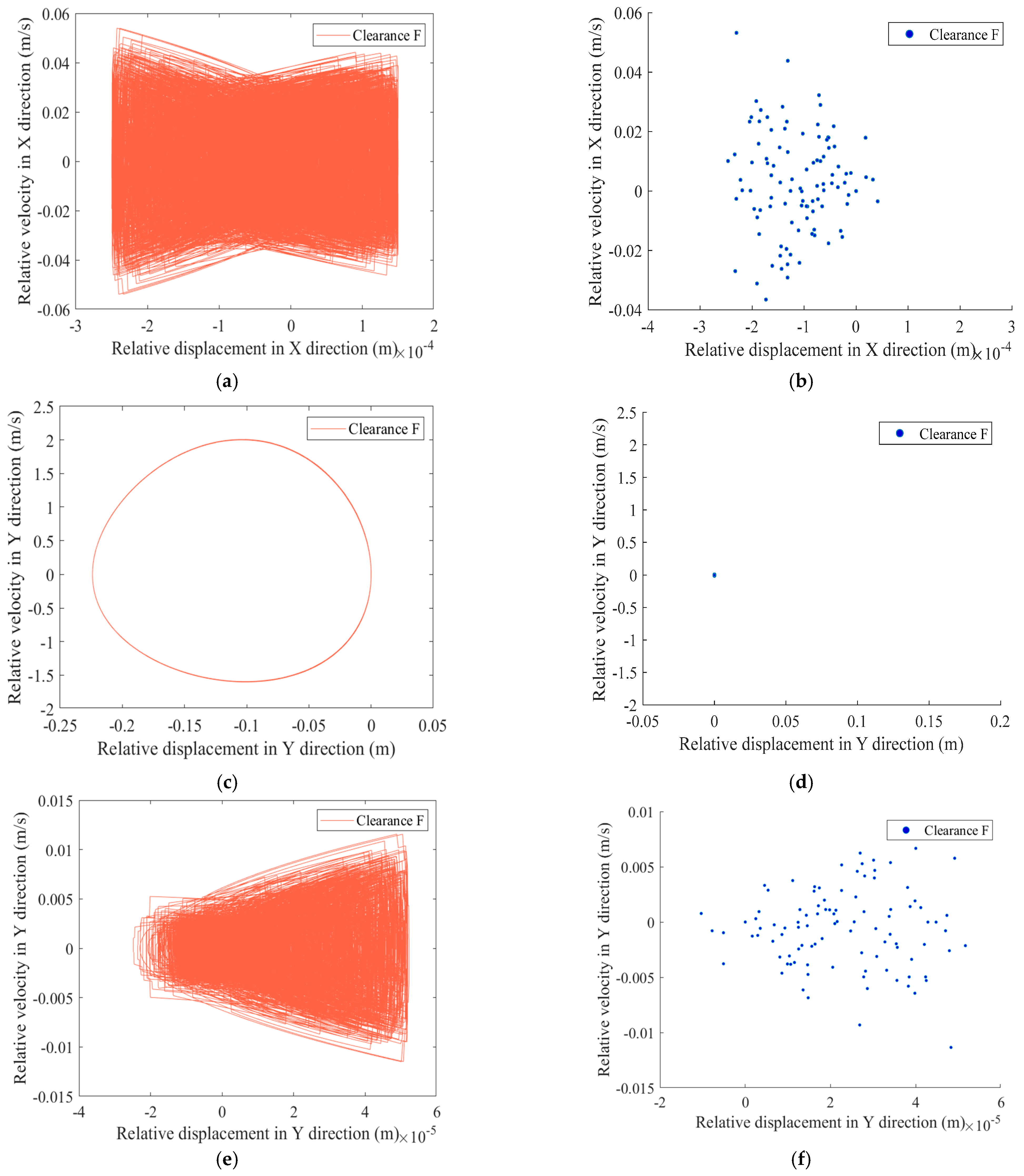
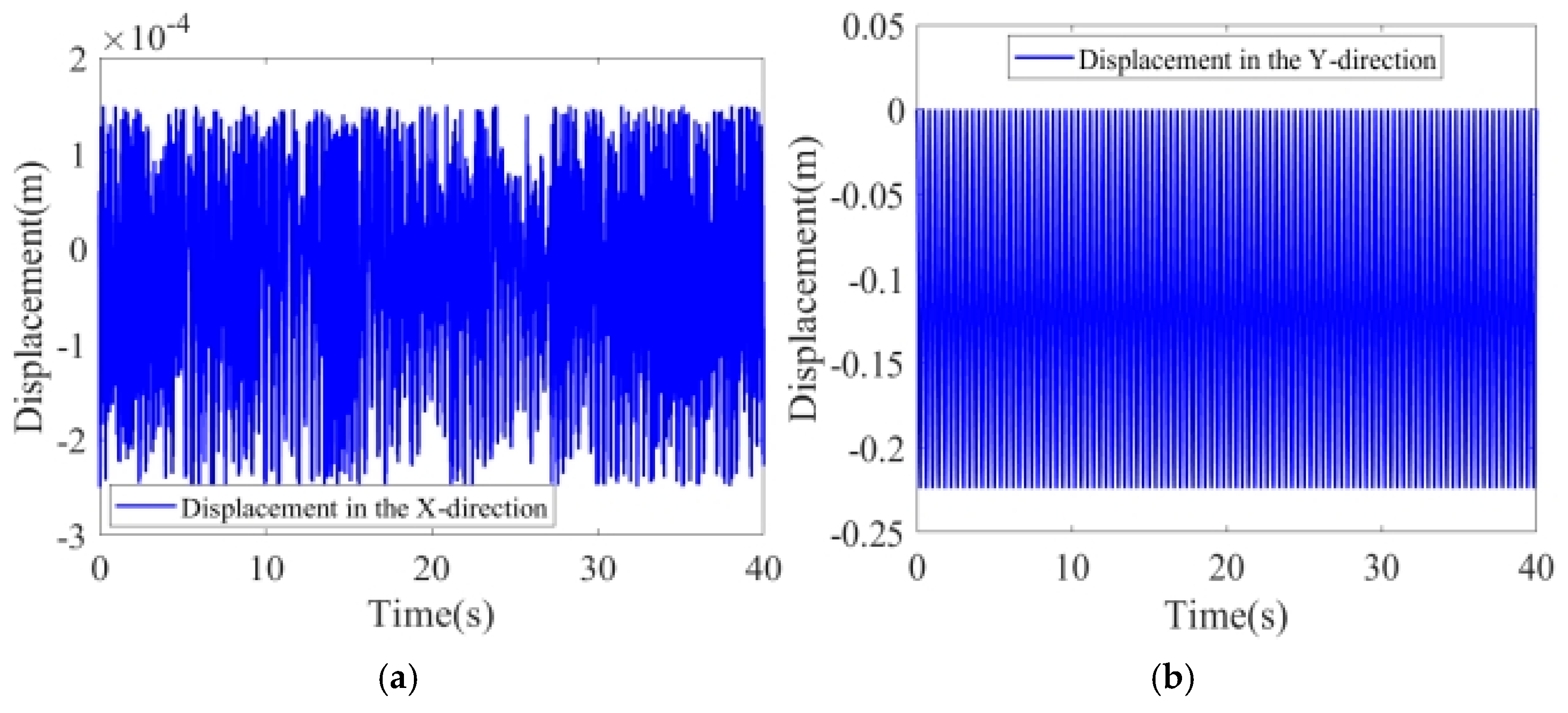
4.7. Nonlinear Characteristics Analysis of Clearance-Containing Mechanisms

Sustained chaotic states may induce friction and wear, adversely affecting system stability and longevity. To mitigate nonlinear effects induced by translational pair clearance and driving speed, minimal parameter values of 150 rpm crank speed and 0.2 mm clearance were selected. The horizontal and vertical coordinate ranges of the X-direction phase diagram shown in Figure 14a are [−2.497 × 10⁻⁴, 1.496 × 10⁻⁴] and [−0.05394, 0.05398], respectively. The Y-direction phase diagram in Figure 14c shows that the ranges of the horizontal and vertical coordinates are [−4.928 × 10⁻⁴, 5.239 × 10⁻⁵] and [−1.602, 2.007]. The Poincaré maps presented in Figure 14b,d revealed scattered points in the X-direction, indicative of chaotic dynamics, whereas Y-direction points demonstrated constrained periodic behavior. However, upon closer examination through the magnification of data in the Y-direction, it is evident that a certain level of chaotic behavior also exists in this direction. As illustrated in Figure 14e,f, the phase diagram for the Y-direction presented in Figure 14e indicates respective ranges of [−2.482 × 10⁻⁵, 5.226 × 10⁻⁵] and [−0.01150, 0.01156] for the horizontal and vertical coordinates. Additionally, the Poincaré map for the Y-direction reveals scattered points. Nevertheless, given the relatively small clearance value compared to the displacement stroke, the chaotic behavior in the Y-direction remains subtle and exerts only minimal influence on the mechanism. As shown in Figure 15, the displacement of the slider in the X-direction exhibits frequent oscillations over 100 cycles, whereas the displacement in the Y-direction demonstrates a distinct periodic pattern over the same duration.

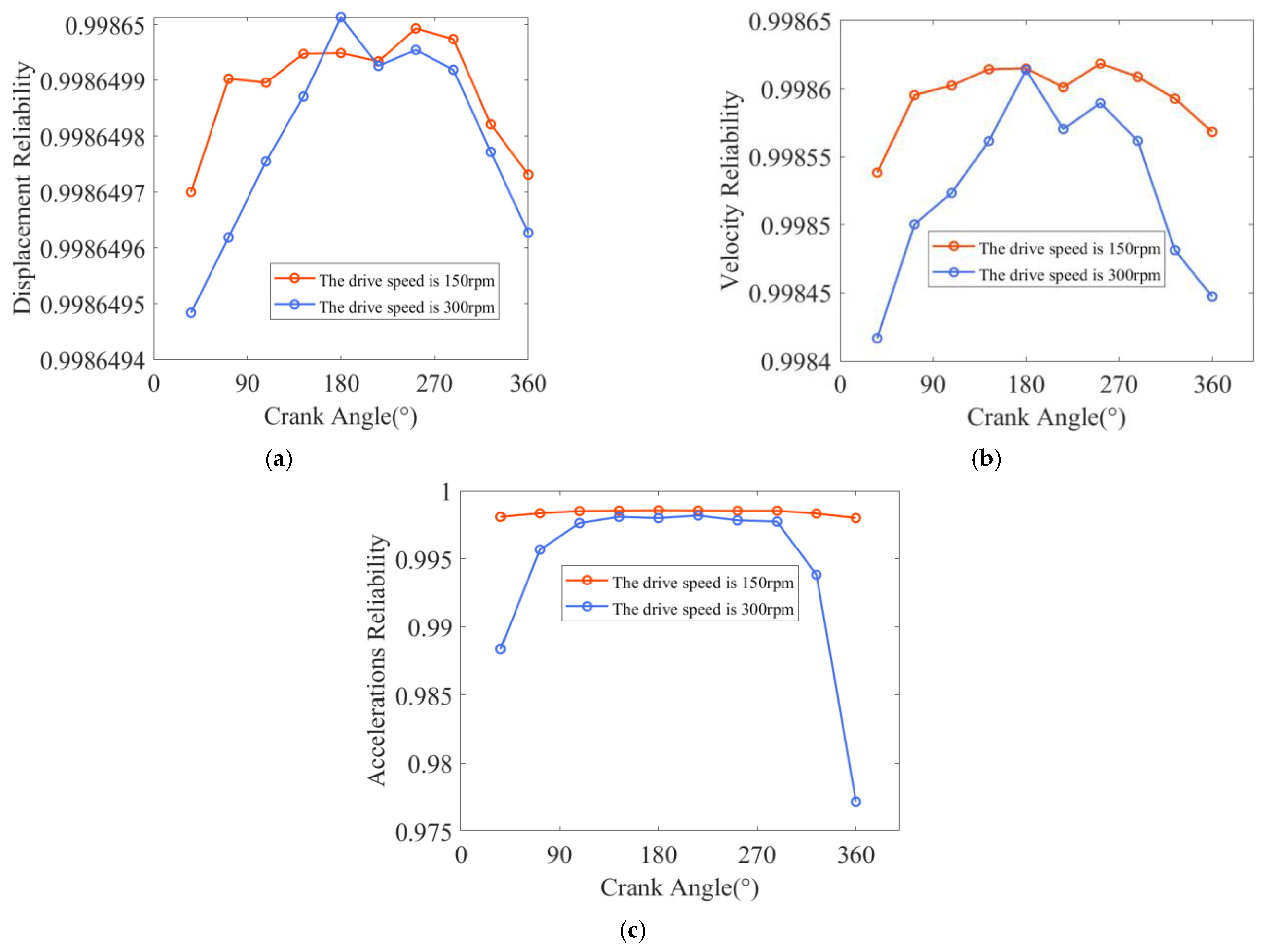
5. Impact on Dynamic Accuracy and Reliability

Operational Reliability Under Variable Clearance Dimensions and Actuation Speeds

Based on dynamic behavior analysis, this section investigates the reliability evolution of slider motion across crank angles during one operational cycle. The reliability metrics under varying translational pair clearances and driving speeds are quantified in Figure 16 and Figure 17.
Figure 16 highlights that under operational conditions of 90 rpm rotational speed, a translational pair with a 0.1 mm clearance, and a crank angle of 72°, the reliability measures for velocity and acceleration reached their lowest points at 0.99864 and 0.99862, respectively. Under these conditions, the displacement reliability attained its minimum value of 0.99865 at a crank angle of 360°. When the translational pair clearance was increased to 0.5 mm while maintaining the same rotational speed of 90 rpm and a crank angle of 36°, the reliability of displacement dropped to its recorded minimum value of 0.99864. Meanwhile, the reliability of velocity and acceleration further decreased to 0.99854 and 0.99852, respectively, at crank angles of 72° and 360°.
Figure 17 demonstrates that under operational conditions with a translational pair clearance of 0.2 mm and a driving speed of 150 rpm, the displacement reliability reached its minimum value of 0.9986497 at a crank angle of 36°. Meanwhile, the velocity and acceleration reliability minima were 0.99842 and 0.99799, occurring at crank angles of 36° and 360°, respectively. At an increased driving speed of 300 rpm with the same 0.2 mm clearance, the displacement reliability decreased to 0.9986495 at a crank angle of 288°. The velocity and acceleration reliability minima were observed at 0.99854 and 0.97719 at crank angles of 36° and 360°, respectively.

6. Conclusions

This study examines a six-bar mechanism within a multi-link mechanical press. An analytical framework was established to incorporate translational pair clearance dynamics into rigid-body formulations through Lagrange multiplier implementation. This approach is complemented by a probabilistic framework that evaluates dynamic accuracy reliability in planar articulated systems with clearance joints, employing first-order statistical moment analysis. The study highlights the importance of researching translational joint clearance for multi-link mechanisms during actual operation by comparing different types of single joint clearances. It systematically compares the dynamic responses and reliability of multi-link mechanisms with translational pair clearance, different material parameters, under different clearance sizes and driving speeds, along with an in-depth analysis of nonlinear characteristics under specific operational conditions.
Key findings indicate that a reduction in the elastic modulus leads to increased motion errors, whereas variations in Poisson’s ratio have a relatively minor effect on dynamic response. Moreover, increased joint clearance and higher driving speeds lead to larger motion errors, thereby reducing the system’s reliability and stability to some extent. Phase diagrams and Poincaré maps reveal that clearance-induced chaotic motion occurs primarily in the X-direction, while periodic oscillations are observed in the Y-direction under certain parameter settings. Prolonged chaotic states can intensify frictional wear, critically compromising long-term reliability and durability. However, as the simulation process omits the effects of material parameters influenced by wear or lubrication conditions, the conclusions drawn are only applicable under short-term operating scenarios. To enhance the lifespan of the mechanism and mitigate the impact of clearance, it is recommended to introduce appropriate lubrication at the moving pairs. This is because the addition of lubricant in the moving pairs with clearance influences the secondary motion of the components, which in turn affects the distribution of the oil film thickness within the clearance. This alteration in oil film thickness consequently changes the pressure distribution of the oil film. Variations in the oil film pressure distribution then affect the motion of the components, leading to more uniform contact between them, reducing localized high pressure and friction, and ultimately alleviating wear and friction.

Author Contributions

Validation, Y.L.; Investigation, J.Z.; Writing—original draft, Q.Z. and M.C.; Funding acquisition, S.J. All authors have read and agreed to the published version of the manuscript.

Funding

This research was funded by [Natural Science Foundation of Shandong Province] grant number [ZR2023QE039], [Open Project of Key Laboratory of Special Motors and High Voltage Electrical Appliances, Ministry of Education] grant number [KFKT202402].

Data Availability Statement

The data used to support the results of this research are included in this paper.

Acknowledgments

This research was supported by the Natural Science Foundation of Shandong Province (Grant No. ZR2023QE039) and the Open Project of Key Laboratory of Special Motors and High Voltage Electrical Appliances, Ministry of Education (Grant No. KFKT202402). We are grateful for the financial support provided by Jiang Shuai for the article processing charge (APC). We also extend our thanks to Mingyang Cai, Yuyang Lian, and Jianuo Zhu for their valuable contributions during the experimental phase of this research.

Conflicts of Interest

Authors declare that they have no conflicts of interest.

References

  1. Chen, X.L.; Yao, E.R. Dynamic characteristics analysis of multi-link mechanism with clearances considering uncertain parameters. Mech. Based Des. Struct. Mech. 2024, 52, 9947–9974. [Google Scholar] [CrossRef]
  2. Jia, P.; Li, D.L.; Zhang, Y.K. A novel reconfigurable parallel mechanism constructed with spatial metamorphic four-link mechanism. Proc. Inst. Mech. Eng. Part C J. Mech. Eng. Sci. 2022, 236, 4120–4132. [Google Scholar] [CrossRef]
  3. Ming, P. Research on the Core Technology and the Development Tendency of Modern Precision Machinery Manufacturing. In Proceedings of the 4th International Conference on Mechanical Materials and Manufacturing Engineering (MMME), Wuhan, China, 15–16 October 2016; Atlantis Press: Wuhan, China, 2016; pp. 806–809. [Google Scholar]
  4. Shi, Y.; Song, B.F.; Yu, T.X. Kinetic Reliability Analysis of Space Four-Links Mechanism Considering Wear. In Proceedings of the 2016 IEEE International Conference on Industrial Engineering and Engineering Management (IEEM), Bali, Indonesia, 4–7 December 2016; IEEE: Bali, Indonesia, 2016. [Google Scholar]
  5. Tian, C.X.; Fang, Y.F.; Guo, S. Structural synthesis of a class of 2R2T hybrid mechanisms. Chin. J. Mech. Eng. 2016, 29, 703–709. [Google Scholar] [CrossRef]
  6. Xiao, H.; Wang, J.; Lyu, S. Error Analysis of a Deployable Scissor-Like Mechanism with Joint Clearances. In Advances in Mechanism and Machine Science, Proceedings of the IFToMM WC 2023, Tokyo, Japan, 5–10 November 2023; Springer: Cham, Switzerland, 2024; pp. 385–394. [Google Scholar]
  7. Zhang, H. Effects of Mixed Joint Clearances on Dynamic Characteristic of Six-bar Mechanism. Mech. Sci. Technol. Aerosp. Eng. 2020, 39, 852–857. [Google Scholar]
  8. Zhao, F.Q.; Gao, Z.Y.; Chen, S.Q. Dynamics Analysis of the Double Push Rod Limb-Leg Mechanism with Clearance Joint. Iran. J. Sci. Technol. Trans. Mech. Eng. 2023, 47, 1799–1827. [Google Scholar] [CrossRef]
  9. Chen, X.L.; Jiang, S.Y. Dynamic response and chaos in planar multi-link mechanism considering revolute clearances. Arch. Appl. Mech. 2020, 90, 1919–1941. [Google Scholar] [CrossRef]
  10. Bai, Z.F.; Ning, Z.Y.; Zhou, J.S. Study on Wear Characteristics of Revolute Clearance Joints in Mechanical Systems. Micromachines 2022, 13, 1018. [Google Scholar] [CrossRef]
  11. Huang, J.; Hu, B.; Sun, S.L.; Xiao, M.T.; Peng, C.W.; Wang, H.B. Mesh Stiffness and Nonlinear Dynamic Model for a Gear Drive with Revolute Pair Clearance. Processes 2023, 11, 230. [Google Scholar] [CrossRef]
  12. Muvengei, O.; Kihiu, J.; Ikua, B. Dynamic analysis of planar multi-body systems with LuGre friction at differently located revolute clearance joints. Multibody Syst. Dyn. 2012, 28, 369–393. [Google Scholar] [CrossRef]
  13. Olyaei, A.A.; Ghazavi, M.R. Stabilizing slider-crank mechanism with clearance joints. Mech. Mach. Theory 2012, 53, 17–29. [Google Scholar] [CrossRef]
  14. Li, X.F.; Zhao, D.; Xie, F.Q.; Wu, S.J.; Li, X.Y. Experimental investigations of the dynamic responses of a multi-link mechanism with revolute clearance joints. Adv. Mech. Eng. 2021, 13, 16878140211012541. [Google Scholar] [CrossRef]
  15. Lin, Y.P.; Wang, J.C.; Zhang, J.L.; An, M.X.; Jiang, S. Research on the Dynamic and Reliability of Planar Multi-Link Mechanisms with Multiple Clearances. Mech. Solids 2024, 59, 1537–1558. [Google Scholar] [CrossRef]
  16. Marques, F.; Isaac, F.; Dourado, N. An enhanced formulation to model spatial revolute joints with radial and axial clearances. Mech. Mach. Theory 2017, 116, 123–144. [Google Scholar] [CrossRef]
  17. Isaac, F.; Marques, F.; Dourado, N. A finite element model of a 3D dry revolute joint incorporated in a multibody dynamic analysis. Multibody Syst. Dyn. 2019, 45, 293–313. [Google Scholar] [CrossRef]
  18. Bai, Z.F.; Liu, T.X.; Li, J.Y.; Zhao, J.J. Numerical and experimental study on dynamic characteristics of planar mechanism with mixed clearances. Mech. Based Des. Struct. Mach. 2023, 51, 6142–6165. [Google Scholar] [CrossRef]
  19. Yang, L.X.; Zhang, X.M.; Huang, Y.J. Dynamic analysis of open-loop mechanisms with multiple spatial revolute clearance joints. Proc. Inst. Mech. Eng. Part C J. Mech. Eng. Sci. 2019, 233, 593–610. [Google Scholar] [CrossRef]
  20. Brutti, C.; Coglitore, G.; Valentini, P.P. Modeling 3D revolute joint with clearance and contact stiffness. Nonlinear Dyn. 2011, 66, 531–548. [Google Scholar] [CrossRef]
  21. Farahan, S.B.; Ghazavi, M.R.; Rahmanian, S. Bifurcation in a planar four-bar mechanism with revolute clearance joint. Nonlinear Dyn. 2017, 87, 955–973. [Google Scholar] [CrossRef]
  22. Zhang, H.; Wu, Q.Z.; Zeng, H.; Meng, L.C.; Luo, Z.; Han, Q.K. Analysis of the Dynamic of Vector Nozzle Adjustment Mechanism Considering the Effect of Joint Clearance. J. Vib. Eng. Technol. 2024, 12, 6137–6154. [Google Scholar] [CrossRef]
  23. Wu, X.Z.; Sun, Y.; Wang, Y.; Chen, Y. Dynamic analysis of the double crank mechanism with a 3D translational clearance joint employing a variable stiffness contact force model. Nonlinear Dyn. 2020, 99, 1937–1958. [Google Scholar] [CrossRef]
  24. Jiang, S.; Chen, X.L. Test study and nonlinear dynamic analysis of planar multi-link mechanism with compound clearances. Eur. J. Mech. A/Solids 2021, 88, 104260. [Google Scholar] [CrossRef]
  25. Wang, S.P.; Cui, Y.; Wang, C.E. Dynamics Analysis and Chaos Identification of Compound Pendulum Jaw Crusher with Joint Clearance. Appl. Sci. 2023, 13, 238. [Google Scholar] [CrossRef]
  26. Ahmedalbashir, M.; Romdhane, L.; Lee, J. Dynamics of a four-bar mechanism with clearance and springs-Modeling and experimental analysis. J. Mech. Sci. Technol. 2017, 31, 1023–1033. [Google Scholar] [CrossRef]
  27. Liu, S.; Cui, Y.; Fu, Y.; Li, B.; Lv, B.L.; Qian, Y.H. Modeling of lubricated translational joints in rigid-partially flexible multibody systems and its application in two-stroke marine diesel engines. Tribol. Int. 2022, 165, 107244. [Google Scholar] [CrossRef]
  28. Erkaya, S.; Dogan, S.; Ulus, S. Effects of joint clearance on the dynamics of a partly compliant mechanism: Numerical and experimental studies. Mech. Mach. Theory 2015, 88, 125–140. [Google Scholar] [CrossRef]
  29. Zheng, X.D.; Li, J.; Wang, Q.; Liao, Q.M. A methodology for modeling and simulating frictional translational clearance joint in multibody systems including a flexible slider part. Mech. Mach. Theory 2019, 142, 103603. [Google Scholar] [CrossRef]
  30. Dong, X.Y.; Sun, Y.; Wu, X.Z.; Wang, R.D. Dynamic modeling and performance analysis of toggle-linkage presses considering mixed clearances and flexibility. Int. J. Non-Linear Mech. 2022, 147, 104243. [Google Scholar] [CrossRef]
  31. Akhadkar, N.; Acary, V.; Brogliato, B. Multibody systems with 3D revolute joints with clearances: An industrial case study with an experimental validation. Multibody Syst. Dyn. 2018, 42, 249–282. [Google Scholar] [CrossRef]
  32. Tan, H.Y.; Li, L.; Huang, Q.; Jiang, Z.D.; Li, Q.X.; Zhang, Y.M.; Yu, D.L. Influence of two kinds of clearance joints on the dynamics of planar mechanical system based on a modified contact force model. Sci. Rep. 2023, 13, 20569. [Google Scholar] [CrossRef]
  33. Jiang, S.; Lin, Y.P.; Liu, J.N.; Xiao, L.J.; Zhang, S.S. Dynamics Optimization Research and Dynamics Accuracy and Reliability Analysis of a Multi-Link Mechanism with Clearances. Machines 2022, 10, 698. [Google Scholar] [CrossRef]
  34. Xiang, W.W.K.; Yan, S.Z.; Wu, J.N.; Niu, W.D. Dynamic response and sensitivity analysis for mechanical systems with clearance joints and parameter uncertainties using Chebyshev polynomials method. Mech. Syst. Signal Process. 2020, 138, 106596. [Google Scholar] [CrossRef]
  35. Gao, Y.; Zhang, F.; Li, Y.Y. Reliability optimization design of a planar multi-body system with two clearance joints based on reliability sensitivity analysis. Proc. Inst. Mech. Eng. Part C J. Mech. Eng. Sci. 2019, 233, 1369–1382. [Google Scholar] [CrossRef]
  36. Chen, X.L.; Gao, S. Dynamic response and dynamic accuracy reliability of planar mechanism with multiple lubricated clearances. Multibody Syst. Dyn. 2023, 57, 1–23. [Google Scholar] [CrossRef]
  37. Zhan, Z.H.; Zhang, X.M.; Zhang, H.D.; Chen, G.C. Unified motion reliability analysis and comparison study of planar parallel manipulators with interval joint clearance variables. Mech. Mach. Theory 2019, 138, 58–75. [Google Scholar] [CrossRef]
  38. Geng, X.Y.; Wang, X.J.; Wang, L.; Wang, R.X. Non-probabilistic time-dependent kinematic reliability assessment for function generation mechanisms with joint clearances. Mech. Mach. Theory 2016, 104, 202–221. [Google Scholar] [CrossRef]
  39. Zhang, J.F.; Du, X.P. Time-dependent reliability analysis for function generation mechanisms with random joint clearances. Mech. Mach. Theory 2015, 92, 184–199. [Google Scholar] [CrossRef]
  40. Wu, J.N.; Yan, S.Z.; Zuo, M.J. Evaluating the reliability of multi-body mechanisms: A method considering the uncertainties of dynamic performance. Reliab. Eng. Syst. Saf. 2016, 149, 96–106. [Google Scholar] [CrossRef]
  41. Li, Y.; Shang, D.Y.; Fan, X.; Liu, Y. Motion Reliability Analysis of the Delta Parallel Robot considering Mechanism Errors. Math. Probl. Eng. 2019, 2019, 3501921. [Google Scholar] [CrossRef]
  42. Yang, Q.; Ma, H.K.; Ma, J.C.; Sun, Z.L.; Li, C.L. Sensitivity Analysis of Reliability of Low-Mobility Parallel Mechanisms Based on a Response Surface Method. Appl. Sci. 2021, 11, 9002. [Google Scholar] [CrossRef]
  43. Jia, Y.H.; Chen, X.L.; Zhang, L.Z.; Ning, C.S. Dynamic characteristics and reliability analysis of parallel mechanism with clearance joints and parameter uncertainties. Meccanica 2023, 58, 813–842. [Google Scholar] [CrossRef]
  44. Zhan, Z.H.; Zhang, X.M.; Jian, Z.C.; Zhang, H.D. Error modelling and motion reliability analysis of a planar parallel manipulator with multiple uncertainties. Mech. Mach. Theory 2018, 124, 55–72. [Google Scholar] [CrossRef]
  45. Flores, P.; Ambrósio, J.; Claro, J.C.P. Translational Joints With Clearance in Rigid Multibody Systems. J. Comput. Nonlinear Dyn. 2008, 3, 11007. [Google Scholar] [CrossRef]
  46. Li, J.L.; Huang, H.Z.; Yan, S.Z.; Yang, Y.Q. Kinematic accuracy and dynamic performance of a simple planar space deployable mechanism with joint clearance considering parameter uncertainty. Acta Astronaut. 2017, 136, 34–45. [Google Scholar] [CrossRef]
  47. Skrinjar, L.; Slavic, J.; Boltezar, M. A review of continuous contact-force models in multibody dynamics. Int. J. Mech. Sci. 2018, 145, 171–187. [Google Scholar] [CrossRef]
  48. Hou, Y.L.; Wang, Y.; Jing, G.N.; Deng, Y.J.; Zeng, D.X.; Qiu, X.S. Chaos phenomenon and stability analysis of RU-RPR parallel mechanism with clearance and friction. Adv. Mech. Eng. 2018, 10, 1687814017746253. [Google Scholar] [CrossRef]
  49. Li, Y.Y.; Wang, C.; Huang, W.H. Dynamics analysis of planar rigid-flexible coupling deployable solar array system with multiple revolute clearance joints. Mech. Syst. Signal Proc. 2019, 117, 188–209. [Google Scholar] [CrossRef]
  50. Baumgarte, J. Stabilization of constraints and integrals of motion in dynamical systems. Comput. Methods Appl. Mech. Eng. 1972, 1, 1–16. [Google Scholar] [CrossRef]
  51. Chen, X.L.; Gao, S. Dynamic accuracy reliability modeling and analysis of planar multi-link mechanism with revolute clearances. Eur. J. Mech. A/Solids 2021, 90, 104317. [Google Scholar] [CrossRef]
  52. Chen, X.L.; Wang, T.; Gao, S. Dynamic response errors and accuracy reliability for mechanism with multiple lubrication clearance joints. Arch. Appl. Mech. 2023, 93, 525–550. [Google Scholar] [CrossRef]
Figure 1. Translational pair clearance model diagram.
Lubricants 13 00246 g001
Figure 2. Translational pair clearance analysis model.
Lubricants 13 00246 g002
Figure 3. Slider and guide rail contact model. (a) Surface contact. (b) Contact between a plane and a spherical surface.
Lubricants 13 00246 g003
Figure 4. Schematic diagram of the six-bar linkage.
Lubricants 13 00246 g004
Figure 5. Stress-strength interference model.
Lubricants 13 00246 g005
Figure 6. Flowchart of modeling and solving process.
Lubricants 13 00246 g006
Figure 7. Dynamic responses under different single clearance types. (a) Displacement response of the slider. (b) Velocity response of the slider. (c) Acceleration response of the slider.
Lubricants 13 00246 g007
Figure 8. Central trajectory at the clearance location. (a) The central trajectory at clearance point F. (b) The central trajectory at clearance point A.
Lubricants 13 00246 g008
Figure 9. Dynamic response under different elastic modulus. (a) Displacement response of the slider. (b) Velocity response of the slider. (c) Acceleration response of the slider.
Lubricants 13 00246 g009aLubricants 13 00246 g009b
Figure 10. Dynamic response under different Poisson’s ratios. (a) Displacement response of the slider. (b) Velocity response of the slider. (c) Acceleration response of the slider.
Lubricants 13 00246 g010aLubricants 13 00246 g010b
Figure 11. Dynamic behaviors under varying clearance magnitudes. (a) Displacement response of the slider. (b) Velocity response of the slider. (c) Acceleration response of the slider.
Lubricants 13 00246 g011aLubricants 13 00246 g011b
Figure 12. Dynamic responses under varying driving speeds. (a) Displacement response of the slider. (b) Velocity response of the slider. (c) Acceleration response of the slider. (d) Displacement response of the slider. (e) Velocity response of the slider. (f) Acceleration response of the slider.
Lubricants 13 00246 g012aLubricants 13 00246 g012bLubricants 13 00246 g012c
Figure 13. Comparison chart of MATLAB and ADAMS results. (a) Displacement response of the slider. (b) Velocity response of the slider. (c) Acceleration response of the slider.
Lubricants 13 00246 g013
Figure 14. Phase diagrams and Poincaré maps at the translational pair clearance. (a) X-axis phase portrait. (b) Poincaré map of clearance F in the X-axis. (c) Y-axis phase portrait. (d) Poincaré map of clearance F in the Y-axis. (e) Phase diagram after Y-axis differentiation. (f) Poincaré map after Y-axis difference.
Lubricants 13 00246 g014
Figure 15. Displacement oscillations of the slider over 100 cycles. (a) X-direction displacement of the slider. (b) Y-direction displacement of the slider.
Lubricants 13 00246 g015
Figure 16. Reliability characteristics under different clearance magnitudes. (a) Displacement reliability. (b) Velocity reliability. (c) Acceleration reliability.
Lubricants 13 00246 g016
Figure 17. Mechanism reliability under different driving speeds. (a) Displacement reliability. (b) Velocity reliability. (c) Acceleration reliability.
Lubricants 13 00246 g017
Table 1. Component simulation parameters.
ComponentLength of Rod ( m )Centroid Position
Length ( m )
Mass ( kg )Moment of Inertia
( 10 3 kg × m 2 )
Crank 10.045 ( L 1 )0.225 ( L s 1 )0.02 ( m 1 )0.0101 ( J 1 )
Rod 20.29 ( L 2 )0.145 ( L s 2 )0.115 ( m 2 )0.8060 ( J 2 )
Rod 30.79 ( L 3 )0.395 ( L s 3 )0.31 ( m 3 )16.1230 ( J 3 )
Rod 40.24 ( L 4 )0.12 ( L s 4 )0.096 ( m 4 )0.4608 ( J 4 )
Slider 5————0.1703 ( m 5 )0.0263 ( J 5 )
Table 2. Simulation parameters of clearance in the translational pair.
ParameterParameter Values
Slider length L ( m )0.07
Slider width W T ( m )0.05
Slider thickness T ( m )0.05
Maximum static friction speed v 0 ( m / s )0.0001
Transitional velocity for kinetic friction v 1 ( m / s )0.001
Restitution coefficient c e 0.9
Elastic modulus E ( Gpa )210
Poisson’s ratio μ m , μ n 0.28
Frictional coefficient c f 0.15
n 1.5
Disclaimer/Publisher’s Note: The statements, opinions and data contained in all publications are solely those of the individual author(s) and contributor(s) and not of MDPI and/or the editor(s). MDPI and/or the editor(s) disclaim responsibility for any injury to people or property resulting from any ideas, methods, instructions or products referred to in the content.

