Article

Research on the Calculation Method for the Contact Stress of Wind Turbine Main Shaft Bearings Based on Finite Element Analysis

School of Mechanical Engineering, Xinjiang University, Urumqi 830047, China
*
Author to whom correspondence should be addressed.
Lubricants 2025, 13(5), 226; https://doi.org/10.3390/lubricants13050226
Submission received: 18 April 2025 / Revised: 12 May 2025 / Accepted: 17 May 2025 / Published: 18 May 2025

Abstract

:
Under alternating loads, the contact situation for self-aligning roller bearings in the main shaft of a wind turbine is complex. Few methodologies exist for calculating the contact stress of main shaft bearings. We propose a method for calculating the contact stress of main shaft bearings in wind turbines; by simulating alternating loads that affect the turbine’s lifespan with a probability of 99%, analyzing the operational characteristics of the bearings under these loads using the roller slice method, and establishing a load–displacement model, this model serves as the boundary condition for contact stress simulation. We present the approach for building a three-dimensional finite element simulation model of contact stress, followed by model validation. The findings reveal that the maximum stress within the spindle bearing is concentrated in the contact zone, taking on an elliptical configuration. The maximum contact stress, as computed by the proposed method, amounts to 1356.3 MPa, and the bearing’s load-bearing performance adequately fulfills the design requirements. A comparative analysis with the calculation results documented in the existing literature shows that the average discrepancies in the computed outcomes for the roller’s contact with the inner and outer rings are 2.55% and 2.48%, respectively, and this validates the high reliability of the proposed approach. The research conducted in this thesis can further enhance the credibility of the contact stress calculation method for large-scale wind turbine spindle bearings.

1. Introduction

Wind energy is recognized globally as one of the pivotal green energy sources and is strategic for the sustainable development of China. Wind turbines, the primary apparatus for wind power generation, are predominantly installed in sparsely populated areas, such as deserts and grasslands, where wind resources are abundant [1]. Wind turbines are mainly categorized into horizontal-axis type and vertical-axis type turbines [2]. The advantages of horizontal-axis type include high wind energy conversion efficiency, superior power generation performance, and suitability for large-scale wind farms. However, they suffer from high maintenance costs due to the need for nacelle-mounted components at elevated heights and the requirement for a yaw system to align the rotor with changing wind directions. In contrast, vertical-axis wind turbines (VAWTs) feature a rotor shaft perpendicular to the ground, with blades typically arranged in a symmetrical configuration. Their key strengths lie in the elimination of yaw systems and adaptability to urban environments. However, VAWTs exhibit lower wind energy conversion efficiency and more complex aerodynamic designs compared to HAWTs. Given that wind turbines in Xinjiang’s wind farms are predominantly installed in remote wilderness areas—such as deserts and grasslands—this thesis focuses on horizontal-axis wind turbines (HAWTs), leveraging their established advantages in large-scale power generation while addressing challenges in maintenance optimization and operational efficiency for such harsh deployment environments. The main shaft bearing of a wind turbine plays a critical role in supporting the main shaft. Due to the low efficiency of domestic production and the long-term monopolization of this technology by foreign entities, most research is found within various industrial white papers [3,4]. The costs associated with repairing or replacing these bearings are considerable. Although the study of contact stresses in bearings has received significant attention, research on the calculation methods for contact stresses in self-aligning roller bearings used in wind turbines is relatively scarce [5,6]. Thus, investigating these calculation methods is of paramount importance. Clarke et al. [7] utilized ultrasonic techniques to measure the loads on all bearings in the transmission chain of wind turbines, comparing these measurements with simulation results to analyze bearing contact stresses under different methodologies. Cheng et al. [8] investigated the distance of the main shaft bearings on the main shaft, as well as the relationship between contact stress and wind characteristics. Wang et al. [9] developed a model for bearings in offshore wind turbines and conducted experimental validation. Gao et al. [10] applied finite element methods to analyze the contact stresses and subsurface stresses in main shaft bearings. Xu et al. [11] constructed a finite element model for the pitch bearing of a wind turbine and investigated the contact stresses under different wind speed conditions. Jiang et al. [12] developed a five-degree-of-freedom equation concerning the contact forces of main shaft bearings to analyze the contact stresses. Most methods concerning bearing contact stresses are based on Hertzian theory, assuming that deformation occurs only at the contact area between the bearing’s roller and raceway, while the rest of the components are considered rigid [13,14]. The bearings studied using this method are almost all of small dimensions; however, the main shaft bearings of wind turbines are large, and if this approach is still applied, it will affect the calculated values of contact stresses [15] and subsequently influence the evaluation of the overall value and performance of the bearings [16]. Some scholars believe that for the self-aligning roller bearings used in the main shafts of wind turbines, the contact pattern might be a hybrid mode of point contact and line contact [17]. Hu et al. [18] developed formulas for line contact in large-scale wind turbine bearings and compared the calculated results with simulation outcomes. Ying et al. [19] carried out experimental and theoretical research on the vibration patterns of bearing-rotor systems. Some scholars have modeled the entire bearing using finite element software. However, a bearing may contain dozens or even hundreds of rolling elements, each with two contact pairs, totaling dozens to hundreds of contact pairs, and setting the boundary conditions to accurately reflect reality is challenging. This makes the calculations extremely time-consuming and difficult to converge [20,21,22].
Based on the above analysis, for most small bearings, the classical Hertzian theory is applied to calculate the contact stress between the roller and raceway of a bearing [23]; a three-dimensional finite element model can also be used for the calculation. However, for large wind turbine main shaft bearings, the forces are complex, the volume is large, and there are many balls [24]. There is no unified standard for the calculation method of contact stresses in specialized large-scale wind turbine main shaft bearings. When simulating an entire bearing imported into ANSYS 2023R1 software, convergence is rarely achieved [25,26]. A simple model for calculating the contact stress of the wind turbine main shaft bearing is proposed to address the problem of inconsistent calculation methods and difficulties in convergence [27,28]; based on the identified deficiencies and considering the operational characteristics, it is necessary to account for the probability of influence on the lifespan reaching 99% under alternating load conditions over the 20-year operating cycle of the wind turbine. It is crucial to study the contact modes of the bearing under alternating loads. The roller slicing method [29] is used to calculate the corresponding relationship between the contact load and displacement between the rollers and raceways of the spindle bearing, and this relationship is used as the boundary condition for calculating the contact stress between the rollers and raceways of the spindle bearing. Using the sub-model technology [30], only a part of the roller and raceway is used as the simulation object. Based on the research methodologies outlined in references [31,32], it is evident that the low rotational speed and high stiffness of the wind turbine main shaft, combined with the large roller dimensions and complex load distribution of the main shaft bearings, may result in the influence of local roller deformations on contact stresses being masked by overall geometric nonlinearities. Additionally, the lubricant film thickness is sufficient to fully separate the rollers from the raceways. Consequently, the effects of local roller deformation and lubrication are neglected in the scope of this study. The research is mainly carried out in the following chapters.
The first chapter introduces the research background of this paper, elaborates on the current research status at home and abroad, and provides a summary.
The second chapter uses software to calculate the alternating loads on the spindle bearing to analyze the forms of alternating loads acting on the spindle bearing. Under these loads, the working characteristics of the spindle bearing are studied, and the internal load distribution form of the spindle bearing is calculated. The analysis in this section lays the foundation for the subsequent analysis in the following section.
In the third chapter, by employing the roller slicing method, the load–displacement relationship of the spindle bearing is derived and compared with that obtained by other methods. This research serves as the input data for the finite element simulation in the following section.
In the fourth chapter, a simplified finite element simulation model is proposed, and simulation analysis is conducted to calculate the contact stress of the bearing, followed by validation.
In the fifth chapter, we summarize and generalize the conclusions drawn and the phenomena observed in the figures.

2. Analysis of Operating Characteristics of the Main Shaft Bearings Under Alternating Loads

2.1. Analysis of Alternating Loads on the Main Shaft Bearings

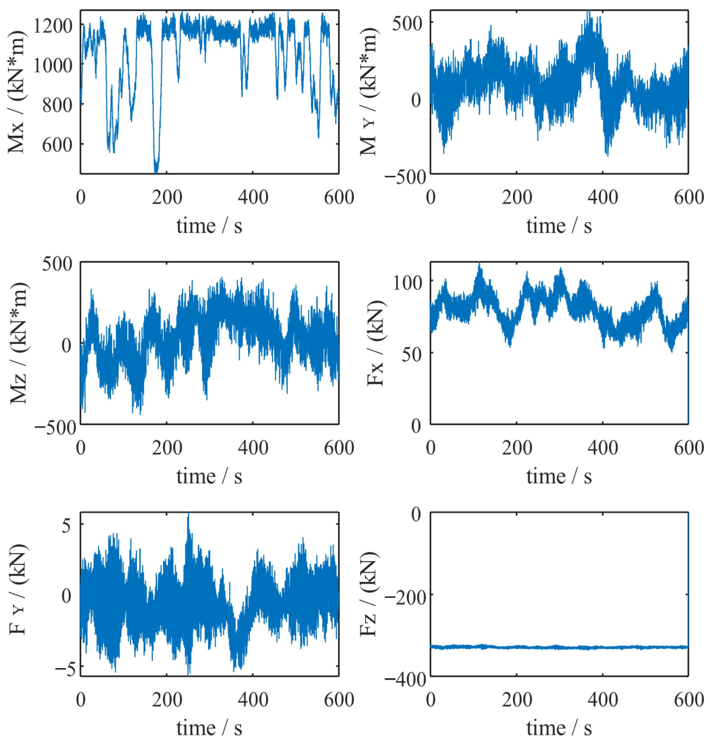
2.1.1. Simulation of Alternating Loads

Figure 1a displays the hub coordinate system of a 2 MW doubly fed wind turbine currently in operation at a wind farm in Xinjiang. This wind turbine features a tri-point bearing configuration, with the following loads acting on the hub center [16]: thrust force (FX), yaw resistance (FY), overturning moment (FZ), driving torque (MX), pitching moment (MY), and yaw resistance moment (MZ). As illustrated in Figure 1b, the loads at the center of the wind turbine hub are transmitted through the main shaft to the main shaft bearing (B1). The loads on B1 include the horizontal force component within the main shaft’s rotational plane Fy1, the force component perpendicular to the rotational plane of the main shaft Fz1, and axial force Fa, with Gs representing the mass at the center of gravity of the main shaft. The distances l1, l2, and l3, respectively, represent the distances from the hub center to the center of the main shaft bearing B1 at the hub end, the distance from the center of B1 to the gearbox, and the distance from the main shaft’s center of gravity to the gearbox.
Based on field investigations conducted at wind farms in Xinjiang, the data presented in Table 1 were obtained. GH Bladed [33] is a professional software widely utilized in the design and analysis of wind turbines. It employs simulation technology to evaluate the load conditions of the hub under various operating scenarios, accurately modeling the dynamic behavior of wind turbines across different operational states and delivering high-precision load calculation results. Consequently, by applying GH Bladed to simulate dynamic loads at the hub [34], it provides a fundamental data basis for analyzing the main shaft bearing’s performance and integrity. As shown in Figure 1, the fixed hub coordinate system described in reference [35] is adopted. Adhering to the right-hand rule, the center of the hub is set as the origin of the coordinate system, and it remains stationary without rotating along with the rotor. The X-direction is aligned with the axial orientation of the main shaft. The Y-axis is perpendicular to the horizontal plane, and the Z-axis is perpendicular to both the X and Y axes, considering scenarios, such as power generation [36], failure occurrence, startup, normal shutdown, and pause. For instance, using DLC1.1aa, the Weibull wind speed model is employed.
As the load data comprise over a hundred conditions, only the eight most frequent scenarios are calculated. These eight scenarios cover over 99% of the total operational probability for the entire 20-year lifespan of the machine [15]. The simulation results, as shown in Figure 2, indicate that the hub loads are alternating. These loads, when transmitted through the main shaft to the bearing, result in the bearing experiencing alternating loads as well.

2.1.2. Equivalent Processing of Alternating Loads

As analyzed in Section 2.1.1, the loads acting on the main shaft bearing are alternating. According to [22], when analyzing the contact characteristics of the main shaft bearing, it is necessary to treat the alternating loads equivalently.
When processing equivalent loads, it is required to set the number of rotations or the duration for a specific scenario. The relationship between a certain operating condition and the mean wind speed under specific conditions is described using the Weibull distribution, with the wind speed probability density function f(v) given by the following Equation (1) [22]:
f ( v ) = k C ( v C ) k 1 e ( C v ) k
where v represents the average wind speed, v = 7.5 m/s, K = 2, and C = 8.46.
F ( v ) = 1 e ( v C ) K
This study assumes that there are, on average, 365 days in a year, with each day having 24 h, totaling 525,600 min per year. The cumulative time for a particular wind speed range, ( ( v i Δ t v i + Δ t ) ), within a year is calculated as in the following Equation (3) [22]:
T i = 525 , 600 v i + Δ t v i Δ t f ( v ) d v
where Δ t = 0.05 (The design requirements standard IEC 61400-1 [22]). This standard recommends a time step size of ≤0.1 s for wind speed time series. A step size of 0.05 s not only meets this requirement but also provides a safety margin. Moreover, the default wind speed time step in mainstream wind turbine design software (e.g., GH Bladed) is set to 0.05 s. Extensive engineering case studies have validated that the computational results obtained with this step size exhibit deviations of <3% compared to measured field data, ensuring both compliance with the standard and practical accuracy in engineering applications.).
The equivalent fatigue load of a wind turbine is calculated using the following formula [35]:
P = p i p n i N p
where p i is the load series for the bearing, p = 10/3, n i is the number of rotations when pi is applied, n i = T i 10 , and N is the total number of rotations, with the main shaft rotating at 15 revolutions per minute (N = 15 × 525,600).
As indicated in Table 2, the values obtained after treating the alternating loads equivalently facilitate the calculation of axial and radial forces experienced by the bearings. Conditions 1–8 correspond to scenarios wherein the probability of reaching or exceeding a 99% lifespan for the wind turbine is achieved.
Based on the equivalent load values from Table 2, and in conjunction with Figure 1b, the radial and axial forces can be determined using the following force balance equations [16].
The radial force equations for the bearing are written as follows:
F y 1 = F Z ( l 1 + l 2 ) + M Y l 3 G s l 2
F z 1 = M Z F Y ( l 1 + l 2 ) l 2
F r = F y 1 2 + F z 1 2
The axial force of the bearing is equal to the thrust force of the wind rotor [16], as in the following Equation (8):
F a = F X
The force value acting on the bearing are presented in Table 3.

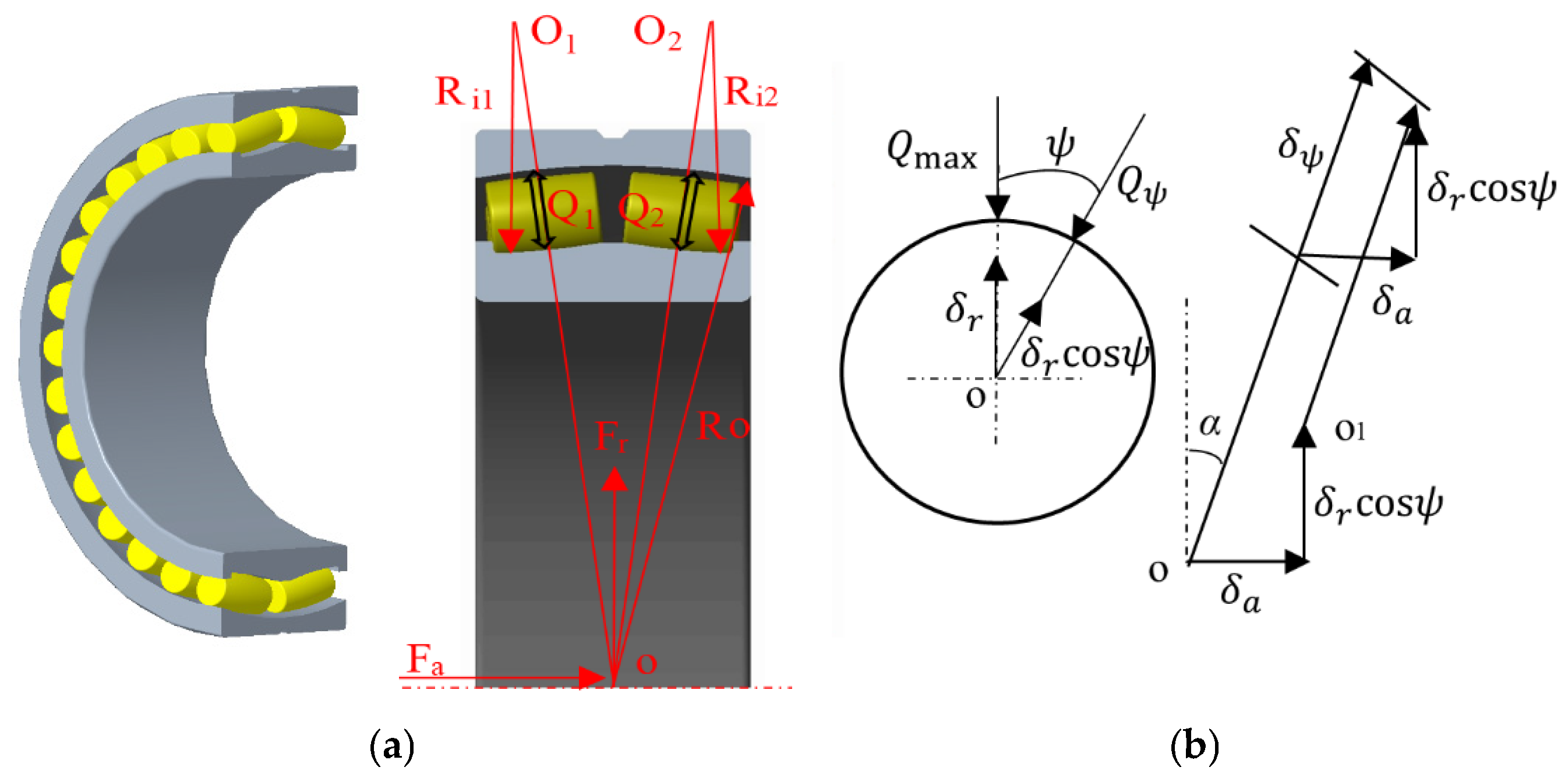
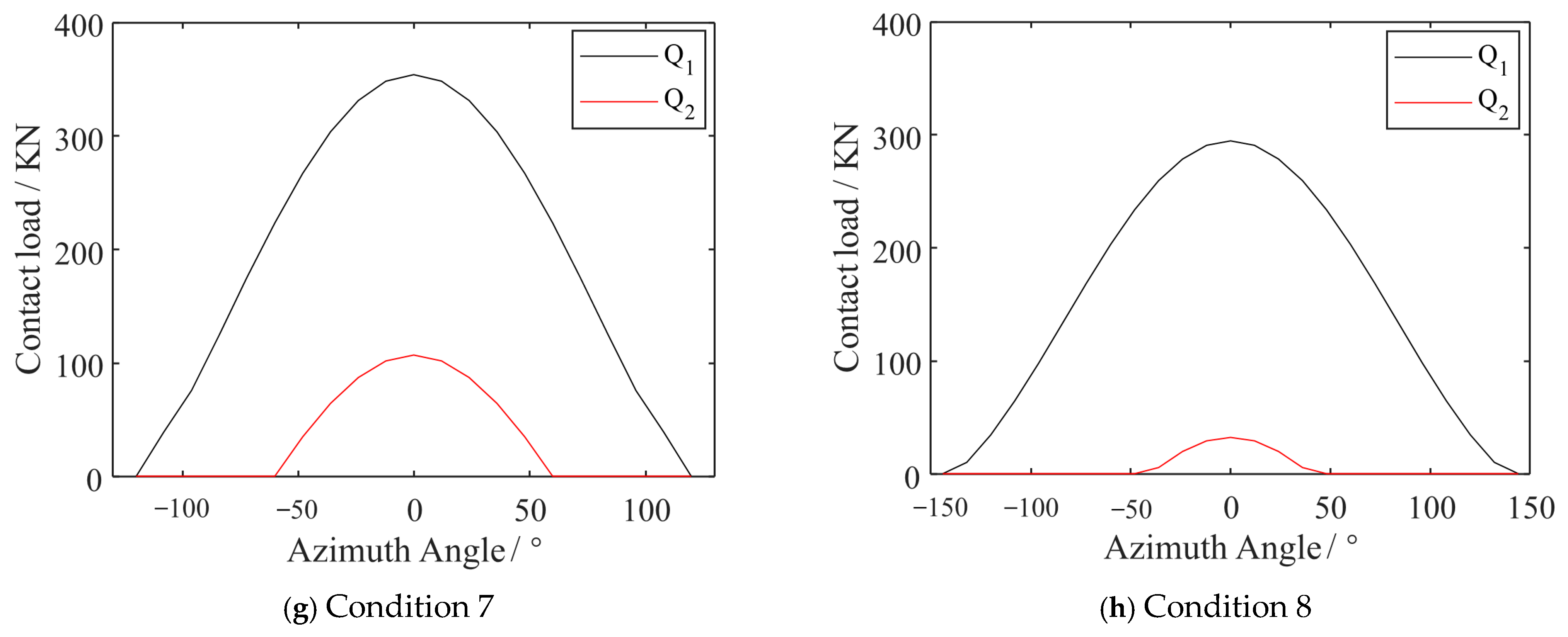
2.2. Analysis of Load Distribution Characteristics of Spindle Bearings Under Alternating Loads

Figure 3a illustrates the structure and operating principle of the bearing of a 2 MW wind turbine. This bearing is a self-aligning roller bearing, model 240/750ECA/W33. The bearing’s outer raceway is spherical, marked at the center point as “o” with a radius of Ro, while the inner raceway is circular. The radii of the first and second rows are Ri1 and Ri2, respectively, with Q1 and Q2 representing the contact loads on the first and second rows.
In Figure 3b, starting from the position of maximum roller load under the influence of Fr and Fa, ψ represents the position of the roller at any angle, α represents the contact angle, and δr and δa, respectively, represent the radial and axial displacements. The displacement when the inner ring operates relative to the outer ring is depicted as follows in Equation (9) [21]:
δ ψ 1 , 2 = δ a 1 , 2 sin α + δ r 1 , 2 cos α cos ψ 1 , 2 c 2
When ψ = 0, the roller displacement is at its maximum, as follows:
δ max 1 , 2 = δ a 1 , 2 sin α + δ r 1 , 2 cos α c 2
δ ψ 1 , 2 = δ max 1 , 2 [ 1 1 2 ε 1 , 2 ( 1 cos ψ 1 , 2 ) ]
ε 1 , 2 = 1 2 ( 1 + δ a 1 , 2 δ r 1 , 2 tan α )
δ max 2 δ max 1 = ε 2 ε 1
ε 1 + ε 2 = 1
The load between the inner and outer rings has the following relationship [26]:
Q max 2 Q max 1 = ( ε 2 ε 1 ) 2
According to the principle of static equilibrium, Equations (16)–(23) are as follows:
F r = F r 1 + F r 2
F a = F a 1 + F a 2
F r = Z Q max 1 J r cos α
F a = Z Q max 1 J a cos α
J r = J r ( ε 1 ) + Q max 2 Q max 1 J r ( ε 2 )
J a = J a ( ε 1 ) + Q max 2 Q max 1 J a ( ε 2 )
J r ( ε 1 , 2 ) = 1 2 π ψ max ψ max [ 1 1 2 ε 1 , 2 ( 1 cos ψ 1 , 2 ) ] n cos ψ 1 , 2 d ψ 1 , 2
J a ( ε 1 , 2 ) = 1 2 π ψ max ψ max [ 1 1 2 ε 1 , 2 ( 1 cos ψ 1 , 2 ) ] n d ψ 1 , 2
The formula for load variation with azimuthal angle is as follows:
Q ψ 1 , 2 = Q max 1 , 2 [ 1 1 2 ε 1 , 2 ( 1 cos ψ 1 , 2 ) ] 1.11
The azimuth angle is as follows:
ψ 1 , 2 = cos 1 ( 1 2 ε 1 , 2 )
Using the above formulas, the contact load distribution between the rollers and the raceways can be computed [1]. As illustrated in Figure 4, the load on the first row of rollers exceeds that on the second row. It is evident that under alternating load conditions, the loads on each row are not equal. Depending on the operational conditions, the range of load distribution varies, affecting the number of rollers bearing the load. Since the rollers bearing the maximum load are the first to fail, they significantly influence the lifespan of the bearing. In the following work, when calculating contact stress, it is possible to analyze only the rollers bearing the maximum load.

3. Load–Displacement Model of Spindle Bearings Under Alternating Loads

Analysis of Alternating Loads on Main Shaft Bearings

As depicted in Figure 5, the roller has a diameter d, length l, and a radial clearance c. The profile radius R of the roller is approximately equal to Ro. The load Q is applied at position A, and A moves relative to B, with a total displacement distance of δ. δA is the distance of the roller movement, ciA is the initial movement gap between the roller and the raceway, and σiA is the deformation during contact, δB, ciB, and σiB are the geometric parameters. The load–displacement relationship is derived from the following Equation (26) [9]:
c i A = R o 2 x i 2 R 2 x i 2 ( R o R ) + c
where xi represents the coordinate of the ith thin layer in the x-direction. Equation (27) is as follows:
c i B = R i 2 x i 2 R 2 x i 2 ( R i R )
where Ri is the radius of the inner raceway, Ri = Ri1(Ri2). Equations (28)–(31) are as follows:
δ = g i A + g i B + σ i A + σ i B
δ A = g i A + σ i A
δ B = g i B + σ i B
σ i A + σ i B = n q i 35948 × ( 127 ) 0.89 0.9
where giA and giB represent the initial clearances between the outer raceway and the rollers, and the initial clearances between the inner raceway and the rollers, respectively, while qi is the load on the ith thin layer and n is the number of thin layers.
The load–displacement relationship is expressed as follows:
Q = k d δ 1.5
where kd represents the load–displacement coefficient, as discussed in the literature, and k d = 1.88 × 10 7 .
For line contact, the load–displacement relationship is given by the following Equation (33):
Q = k X δ 1.11
where kX denotes the load–displacement coefficient, as discussed in the literature, and k X = 5.82 × 10 6 .
In combination with Table 4, the load–displacement relationship curve in Figure 6 is obtained. When the load is small, the contact form exhibits point contact characteristics. As the load increases, the contact form gradually approaches line contact. This indicates that the contact characteristics of the bearing change with the magnitude of the load [33]. These patterns aligns with the descriptions the in literature [16]. The load–displacement relationship data will serve as the boundary conditions for the finite element simulation in the next section.

4. Simulation Verification and Comparative Analysis of Results

4.1. Finite Element Simulation and Verification

4.1.1. Parameter Settings and Simulation of the Finite Element Model

Figure 7 illustrates the process of establishing a finite element model, described in detail as follows:
(1)
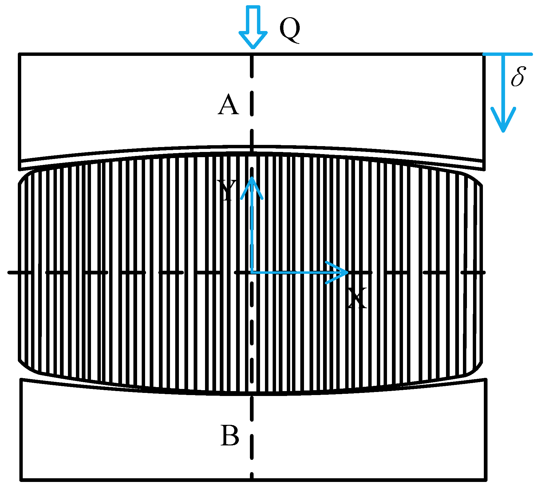
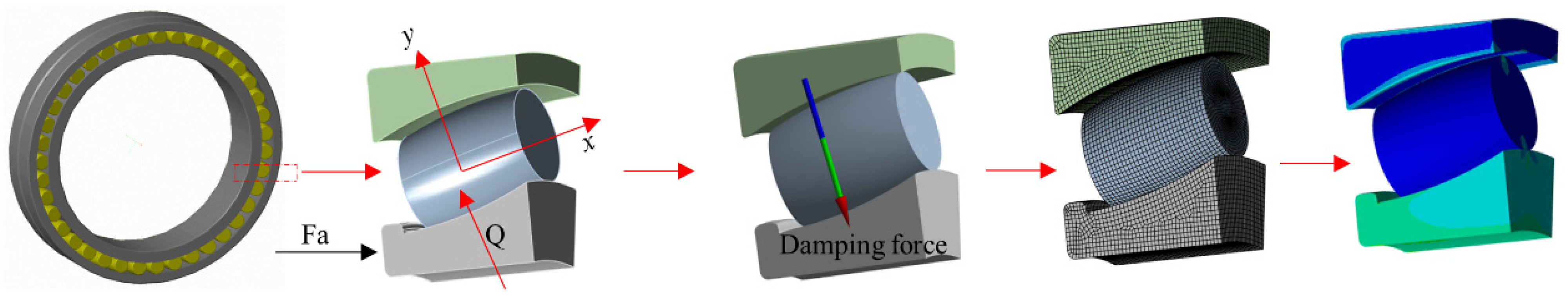
Model simplification: Due to the bearing’s symmetrical properties, a segment including one roller and its immediate surroundings is selected as the subject of study.
(2)
Boundary conditions settings: Load–displacement data obtained from Section 2 are imported as boundary conditions. During operation, the outer ring is fixed in the bearing housing [35]; thus, it is fully constrained on its surface, while the inner ring is allowed to rotate, constraining its circumferential displacement. The outer ring is set with elastic support to permit deformations during operation, and both the rollers and the rings are treated as flexible bodies. The roller can move freely in the y-direction, while it is fixed and constrained in the x- and z-directions. The y-direction is perpendicular to the inner ring. The normal load corresponds to the maximum load value for each operational condition, and the axial force direction is perpendicular to the face of the ring [27].
(3)
The friction coefficient is set at 0.05. Due to the presence of radial clearance, the “PINB” command in the finite element software is used to close the initial gap. To ensure convergence, artificial damping forces are added in the form F L = L M Δ v , where L = 0.002, representing the damping coefficient. The load is incrementally applied according to time steps, and the damping force is proportional to the velocity. Initially, the roller moves at a high speed, and the presence of the damping force prevents computational divergence. After a period, once the roller contacts the raceway, the damping force becomes zero, not affecting the results.
(4)
Multiscale mesh division: To conserve computational resources, the mesh at the contact areas between the roller and the inner/outer rings is finely divided into 0.5 mm areas. Other areas are meshed at 5 mm using a hexahedral sweeping grid division.

4.1.2. Finite Element Model Validation

(1)
The influence of the number of meshes on the model
The number of mesh elements is a critical factor, which in turn impacts the accuracy of the computed results. Therefore, it is essential to ensure the precision of displacement and stress calculations. Taking Condition 7 as an example, the convergence of the displacement and maximum contact stress is verified by varying the number of mesh in the contact area. Through calculations, it has been found that the contact stress between the roller and the inner ring is greater than that between the roller and the outer ring [36]. Therefore, it is only necessary to validate the stress conditions at the roller–inner ring interface. As shown in Figure 8, when the mesh count includes 55,000, 56,000, and 56,694 elements, both the displacement and maximum contact stress stabilize. This confirms the model’s convergence and subsequently validates the model. Thus, using the aforementioned method for calculating contact stress is reasonable.
(2)
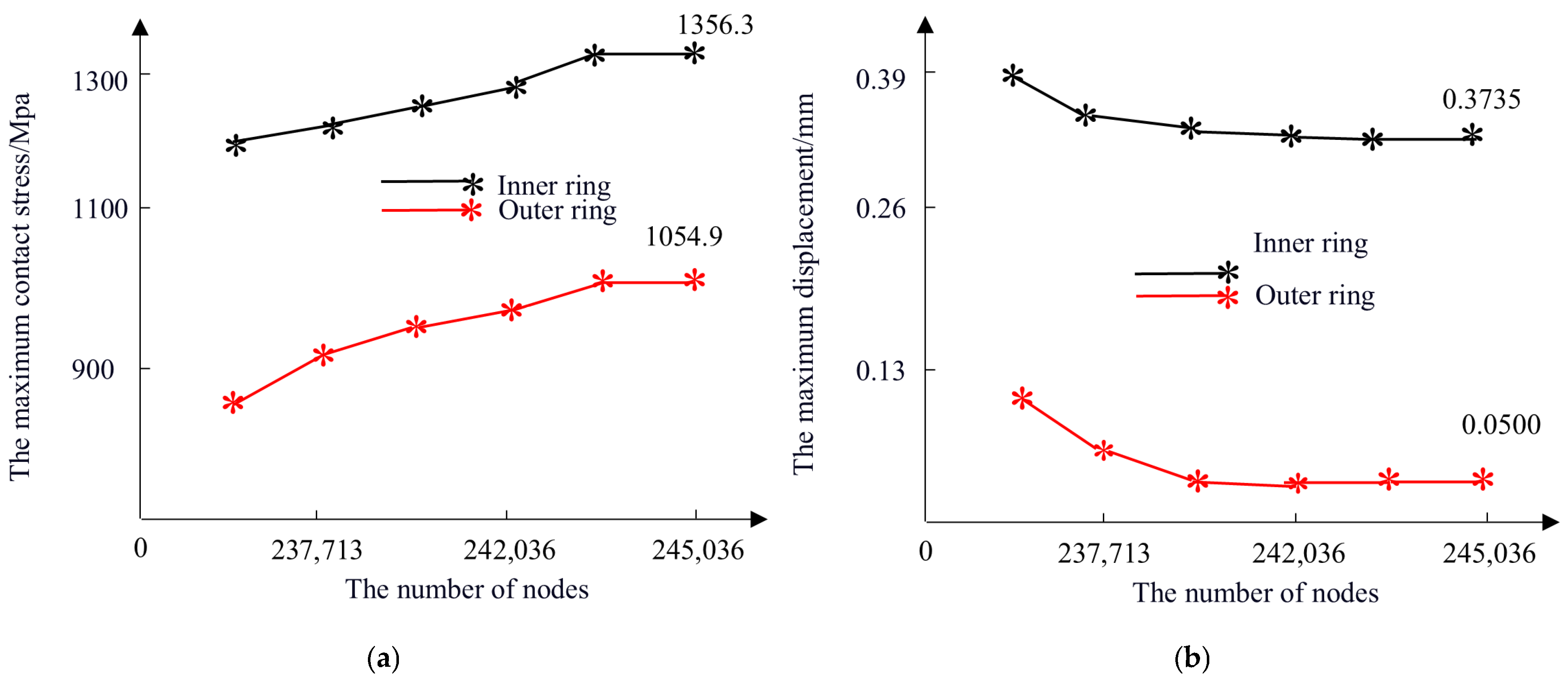
The impact of node count on computational results
As illustrated in Figure 9a,b, which depict the relationships between the number of nodes and both contact stress and displacement in simulations using hexahedral elements, it can be observed that when the node count approaches 245,036, both the maximum contact stress and maximum displacement tend to stabilize. Therefore, a node count of 245,036 is deemed optimal.
(3)
The influence of the number of roller slices on computational results
The number of roller slices has an impact on the calculation of contact stress. Too few slices can lead to smoothing of the stress concentration area, while too many slices can increase the computational cost. Therefore, it is necessary to determine the number of roller slices reasonably to ensure that the maximum value of the contact stress does not fluctuate significantly with the increase in the number of slices. Taking Condition 7 as an example, as shown in Figure 10, the number of roller slices and the maximum contact stress are shown. When the number of roller slices is 70, the maximum contact stress of the inner ring converges to 1356.3 Mpa, and when the number of roller slices is 65, the maximum contact stress of the outer ring converges to 1054.9 Mpa. Therefore, the number of roller slices is selected to be 70.

4.2. Simulation Results and Comparative Analysis

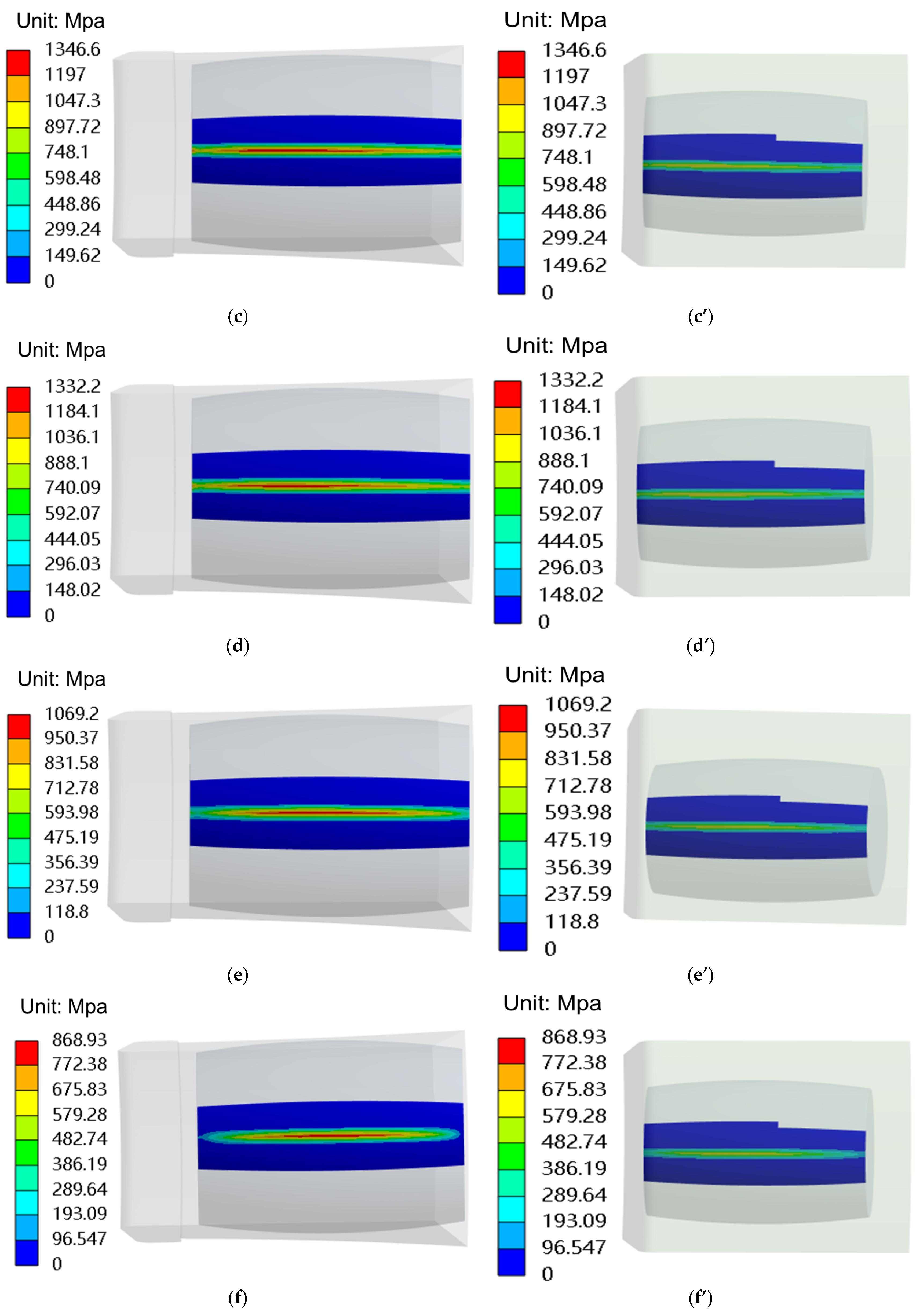
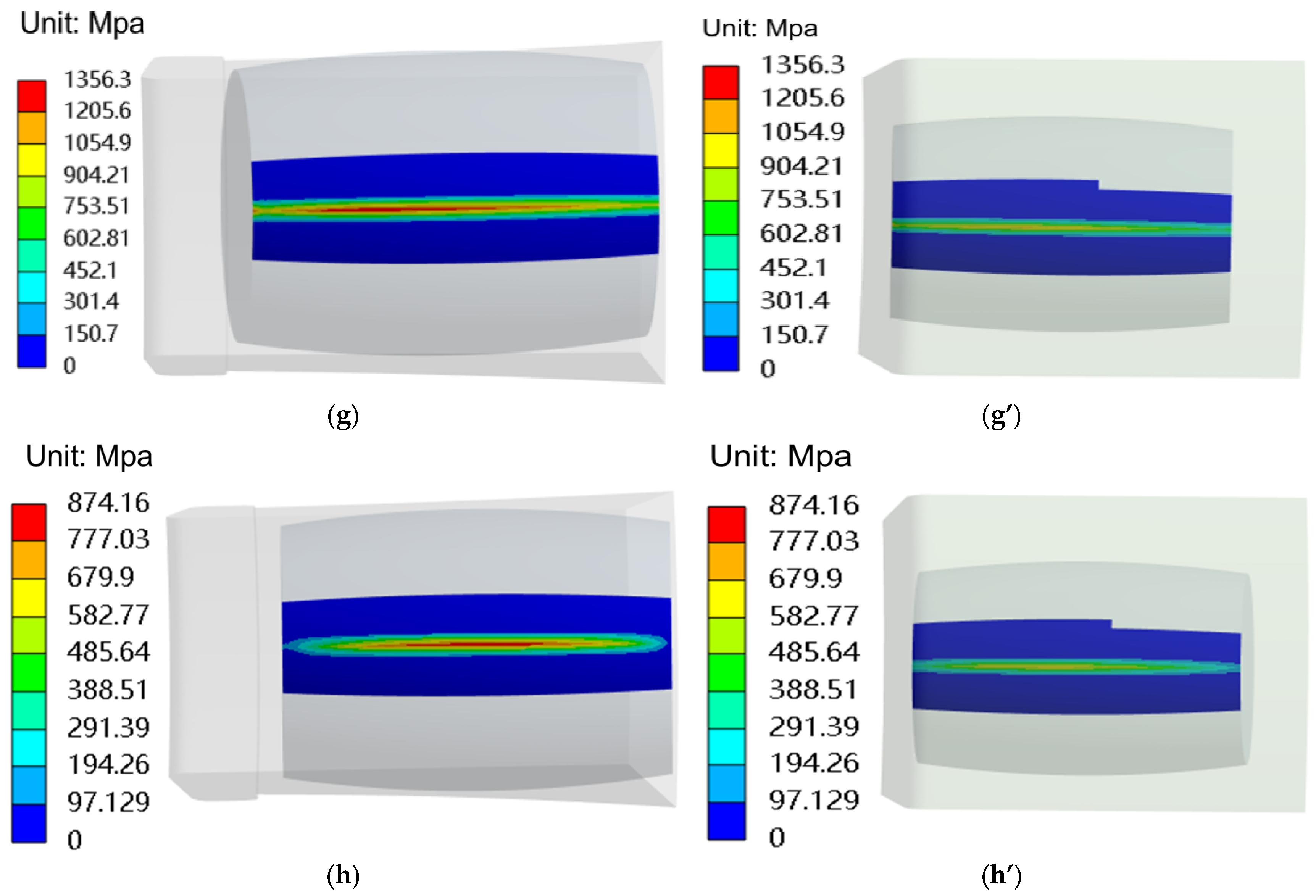
4.2.1. Simulation Results Analysis

Figure 11 illustrates the contact stress distribution contours at the roller–inner race and roller–outer race interfaces, computed using the proposed computational method under eight operating conditions (Conditions 1–8). In each contour plot, the color bar on the left-hand side transitions from red to blue, indicating a decreasing gradient of contact stress values.
(1)
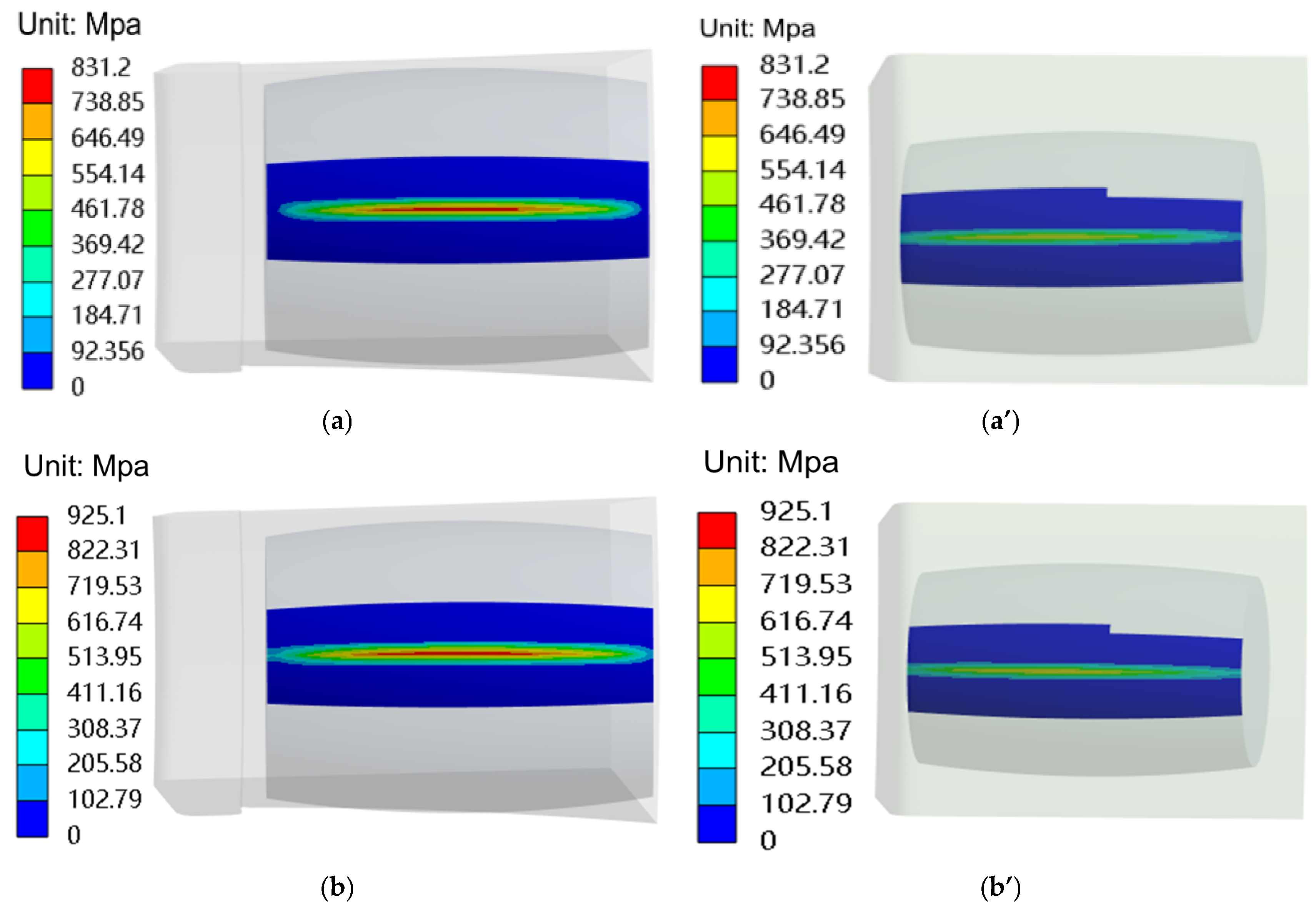
Regardless of whether the roller contacts the inner race or the outer race, the maximum contact stress consistently occurs at the geometric center of the contact zone. The stress magnitude peaks within the contact region and gradually diminishes with increasing distance from the center, exhibiting a characteristic elliptical stress distribution pattern. This finding aligns with the results reported in references [28,29].
(2)
The contact stress magnitudes between the roller and raceway vary significantly under different operating conditions. The inner ring contact stresses are consistently higher than those of the outer ring, and the areas around the contact point tend to be elliptical, with the highest stress occurring in the contact region. Thus, during the operation of the bearing, the contact area is most susceptible to damage, necessitating focused consideration in bearing contact analysis.
(3)
Under the specified operating conditions, the maximum contact stress between the roller and inner race reaches 1356.3 MPa, while that between the roller and outer race attains 1054.9 MPa. These findings indicate that, to ensure structurally intact operation of the wind turbine main shaft bearing throughout its service life, the roller–raceway interface must sustain peak contact stresses of at least 1356.3 MPa without failure. According to the literature [16], the limit for roller–raceway contact stress is 1500 MPa, indicating that this design is within acceptable standards and that the bearing has sufficient load capacity.

4.2.2. Verification of the Correctness of the Computational Method

To validate the correctness of the contact stress calculation method and its applicability under various operating conditions, verification was conducted based on the scenarios outlined in reference [29,30]. This reference employs the Hertzian contact theory and dynamic stiffness simulation for contact stress analysis. The computational results obtained in this study, along with those from reference [30] and the corresponding errors between them, are presented in Table 5. As shown in Table 5, when compared with the calculated results from reference [30], the maximum error for the maximum contact stress in the inner ring is 5.3%, with a minimum error of 0.8% and an average error of 2.55%. For the outer ring, the maximum error is 5.06%, with a minimum error of 0.07% and an average error of 2.48%. Based on the studies in references [29,30], the calculated results from the proposed method exhibit excellent agreement with those reported in the literature, thereby validating the correctness of the proposed computational approach. The potential sources of these discrepancies may be attributed to factors, such as element discretization, numerical integration, and deformation assumptions inherent in the finite element model utilized in this study [30].

4.2.3. Simulation Results Comparison
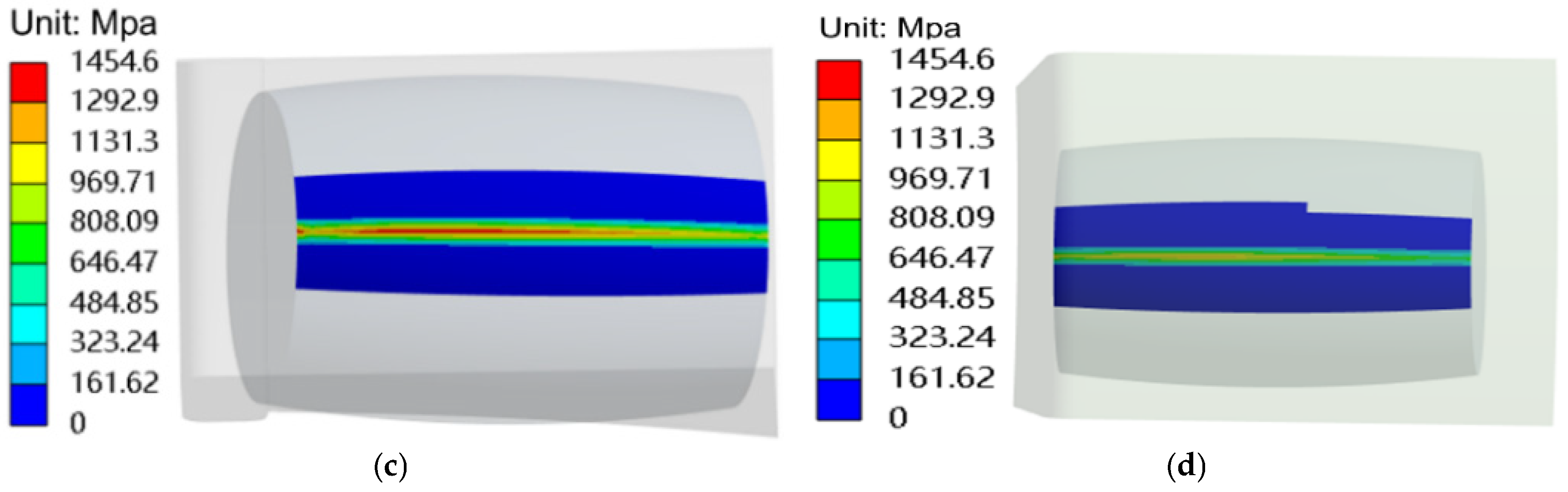
As analyzed in Section 4.2.1, Condition 1 experiences the minimum load while Condition 7 experiences the maximum load, with other conditions bearing loads that fall between these two extremes. Therefore, analyzing the conditions with the maximum and minimum loads is particularly representative.
(1)
In the analysis of contact stress for wind turbine main shaft bearings, linear contact models are predominantly used [7,8,9,10,11]. Figure 12 provides a comparison using the linear contact model to derive the load–displacement relationship as a boundary condition, resulting in calculated contact stresses.
(2)
Figure 12a,b show the inner and outer ring contact stresses for Condition 1, which are 910.83 MPa and 607 MPa, respectively. Figure 12c,d depict the inner and outer ring contact stresses for Condition 7, which are 1454.6 MPa and 969 MPa, respectively, with the maximum contact stress being 1454.6 MPa.
(3)
By integrating the operational conditions (condition 1 and condition 7) illustrated in Figure 11 and Figure 12, the analysis indicates that the maximum contact stresses calculated using the proposed method are lower than those obtained by other methods under the same conditions. For the overall wind turbine, analyzing bearing contact stress using the proposed method is relatively safer and more conservative.
In summary, when designing main shaft bearings, it is essential to consider the contact form between rollers and raceways comprehensively rather than solely focusing on point or line contact. Different contact models can yield varying contact stress results, which, in turn, affect the load-bearing capacity of the bearings.

5. Conclusions

This study focuses on the main shaft’s double-row self-aligning roller bearings in a 2 MW wind turbine under the influence of alternating loads. By analyzing the operational characteristics and contact forms of the main shaft bearings, the load–displacement relationship under alternating loads is established, and contact stress is computed using finite elements and validated. The conclusions are as follows:
(1)
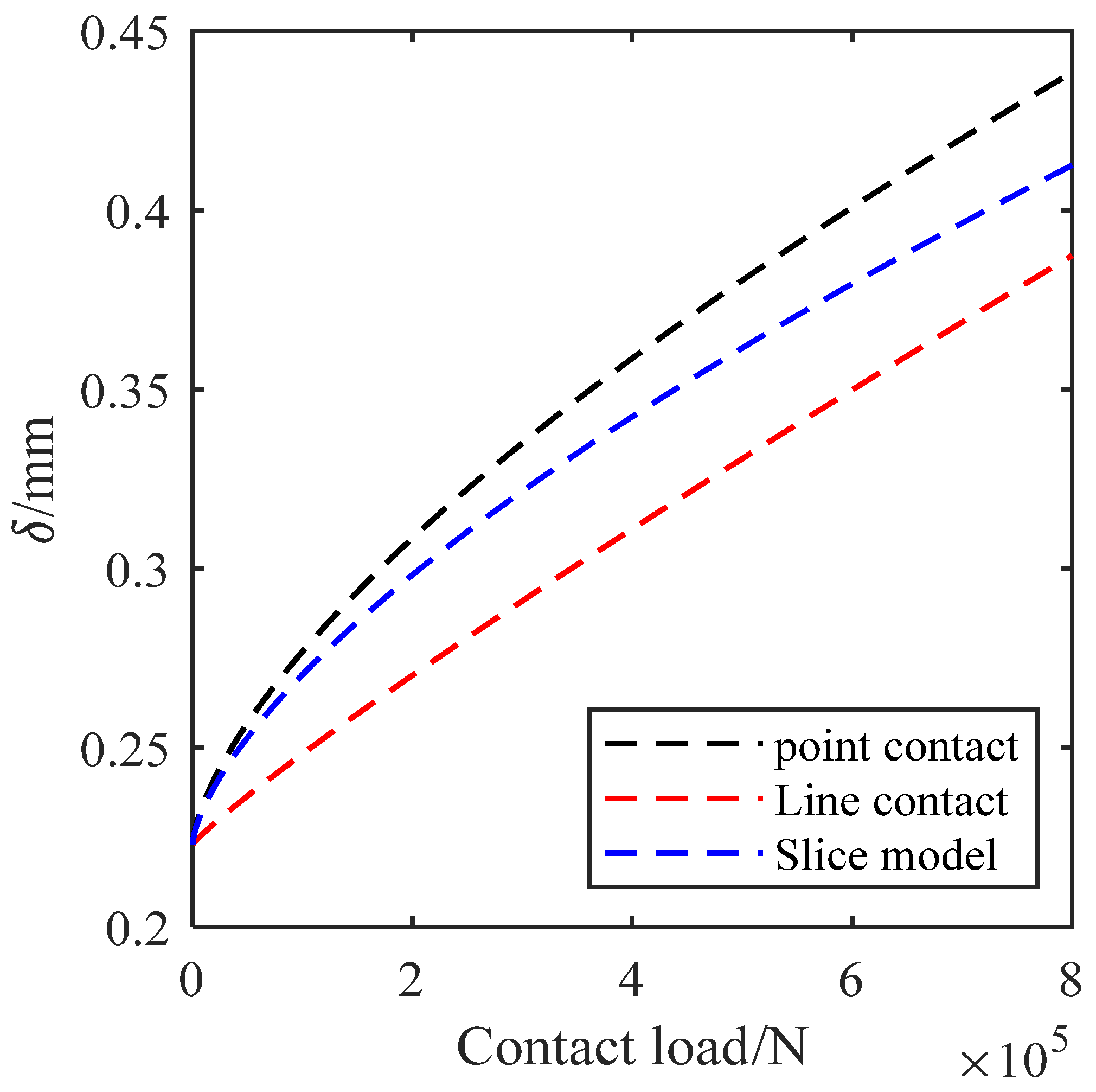
Under alternating loads, the load–displacement defined by the roller slice model reveals that the contact form of the main shaft bearing involves both point and line contacts.
(2)
In the contact area, the local contact area is similar in shape to an ellipse, with the highest stresses at the contact center. As the distance from the contact center gradually increases, the contact stress progressively decreases. This area is more prone to damage; thus, emphasis should be placed on analyzing the stresses in the contact area during research.
(3)
When compared with the computational results reported in the literature, the proposed method exhibits a maximum error of 5.3% and an average error of 2.55% for the maximum contact stress value at the inner ring, while the maximum error for the maximum contact stress at the outer ring is 5.06%, with an average error also at 2.48%. These findings collectively validate the high reliability of the proposed method.
(4)
When the roller is discretized into 70 slices, the maximum contact stress between the bearing roller and raceway approaches convergence. Similarly, when the mesh node count reaches 245,036, both the maximum contact stress and maximum displacement at the roller–raceway interface exhibit near-convergence behavior. By setting these parameters during simulation, the reliability of the computational model is effectively ensured.
(5)
Using the proposed method, the maximum contact stress calculated was 1356.3 MPa, compared to using a linear model as the boundary condition. Both computational methods fully comply with the full-lifecycle standards for wind turbine main shaft bearings, but the proposed method enhances the safety of bearing analysis. It is essential to focus on analyzing contact forms to obtain reasonable contact stress results.

Author Contributions

Conceptualization, Y.Z. and W.S.; methodology, Y.Z.; software, Y.Z.; validation, Y.Z., H.W., T.X. and B.W.; formal analysis, Y.Z.; investigation, B.W. and T.X.; resources, W.S. and H.W.; data curation, Y.Z.; writing—original draft preparation, Y.Z.; writing—review and editing, Y.Z.; visualization, Y.Z.; supervision, Y.Z.; project administration, Y.Z.; funding acquisition, W.S. and H.W. All authors have read and agreed to the published version of the manuscript.

Funding

This research is supported by National Natural Science Foundation of China (grant no. 51565055); the Autonomous Region Key Research and Development Program (grant no. 202112142); and the Autonomous Region Natural Science Foundation (grant no. 2022D01C390).

Institutional Review Board Statement

Not applicable.

Informed Consent Statement

Not applicable.

Data Availability Statement

The raw data supporting the conclusions of this article will be made available by the authors on request.

Acknowledgments

We would like to thank all the authors in the laboratory.

Conflicts of Interest

The authors declare no conflicts of interest.

References

  1. Lu, Q.; Li, M. Digital Twin-Driven Remaining Useful Life Prediction for Rolling Element Bearing. Machines 2023, 11, 678. [Google Scholar] [CrossRef]
  2. Farajyar, S.; Ghafoorian, F.; Mehrpooya, M.; Asadbeigi, M. CFD Investigation and Optimization on the Aerodynamic Performance of a Savonius Vertical Axis Wind Turbine and Its Installation in a Hybrid Power Supply System: A Case Study in Iran. Sustainability 2023, 15, 5318. [Google Scholar] [CrossRef]
  3. Moghadam, F.K.; Nejad, A.R. Online condition monitoring of floating wind turbines drivetrain by means of digital twin. Mech. Syst. Signal Process. 2022, 162, 108087. [Google Scholar] [CrossRef]
  4. Wang, S.S.; Torgeir, M.; Jiang, Z. Influence of variability and uncertainty of wind and waves on fatigue damage of a floating wind power drivetrain. Renew. Energy 2022, 181, 870–897. [Google Scholar] [CrossRef]
  5. Torsvik, J.; Nejad, A.R.; Pedersen, E. Experimental field study of floater motion effects on a main bearing in a full-scale spar floating wind turbine. Mar. Struct. 2021, 79, 103059. [Google Scholar] [CrossRef]
  6. Dhanola, A.; Garg, H.C. Tribological challenges and advancements in wind power bearings: A review. Eng. Fail. Anal. 2020, 118, 104885–104914. [Google Scholar] [CrossRef]
  7. Clarke, B.; Nicholas, G.; Hart, E.; Long, H.; Dwyer-Joyce, R. Loading on a wind turbine high-speed shaft gearbox bearing: Ultrasonic field measurements and predictions from a multi-body simulation. Tribol. Int. 2023, 181, 108319. [Google Scholar] [CrossRef]
  8. Cheng, S.; Meng, X.; Yin, J.; Yang, L.; Zhang, J. Configuration performance of main shaft bearings for transient-loaded wind turbine. Int. J. Mech. Sci. 2025, 293, 110171. [Google Scholar] [CrossRef]
  9. Wang, Z.; Pu, W.; Pei, X.; Cao, W. Nonlinear Dynamical Behaviors of Spiral Bevel Gears in Transient Mixed Lubrication. Tribol. Int. 2021, 160, 107022. [Google Scholar] [CrossRef]
  10. Gao, X.H.; Zhang, Z.K. A simplified spherical roller bearing model and its application in the wind turbine main bearing system finite element modeling. Tribol. Int. 2024, 196, 109678. [Google Scholar] [CrossRef]
  11. Xu, J.W.; Benson, S.; Wetenhall, B. Comparative analysis of fatigue life of a wind turbine yaw bearing with different support foundations. Ocean Eng. 2021, 235, 109293. [Google Scholar] [CrossRef]
  12. Jiang, Z.; Huang, X.; Zhu, H.; Jiang, R.; Du, S. A new method for contact characteristic analysis of the tapered roller bearing in wind turbine main shaft. Eng. Fail. Anal. 2022, 141, 106729. [Google Scholar] [CrossRef]
  13. Smolnicki, T.; Rusi’nski, E. Superelement-based modeling of load distribution in large-size slewing bearings. ASME J. Mech. Des. 2007, 129, 459–463. [Google Scholar] [CrossRef]
  14. Daidi’e, A.; Chaib, Z.; Ghosn, A. 3D simplified finite elements analysis of load and contact angle in a slewing ball bearing. ASME J. Mech. Des. 2008, 130, 082601. [Google Scholar] [CrossRef]
  15. Zhao, W.; Jiang, Z.; Zhang, P.; Huang, X. Reliability Sensitivity Analysis of Main Shaft Bearings of Wind Turbines Subject to Subsurface Stress. Machines 2023, 11, 681. [Google Scholar] [CrossRef]
  16. Jin, S.; Dong, H.; Chen, J.; Xie, X.; Guo, M. Study on accelerated life tests for main shaft bearings in wind turbines. J. Mech. Sci. Technol. 2022, 36, 1197–1207. [Google Scholar] [CrossRef]
  17. ISO 281; Rolling Bearings—Dynamic Load Ratings and Rating Life. ISO: Geneva, Switzerland, 2007.
  18. Hu, Y.; He, L.; Luo, Y.; Tan, A.C.; Yi, C. Contact Load Calculation Models for Finite Line Contact Rollers in Bearing Dynamic Simulation Under Dry and Lubricated Conditions. Lubricants 2025, 13, 183. [Google Scholar] [CrossRef]
  19. Ying, M.; Liu, X. Unbalance Response of a Hydrogen Fuel Cell Vehicle Air Compressor Rotor Supported by Gas Foil Bearings: Experimental Study and Analysis. Lubricants 2025, 13, 181. [Google Scholar] [CrossRef]
  20. Shah, D.B.; Kaushik, M.P.; Ruchik, D.T. Analyzing Hertzian contact stress developed in a double row spherical roller bearing and its effect on fatigue life. Ind. Lubr. Tribol. 2016, 68, 361–368. [Google Scholar] [CrossRef]
  21. Chen, Y.; Jin, X.; Yue, Y.; Wang, S.; Han, H.; Wen, M.; Wang, Q.; Cheng, P. Investigation on 3D fatigue crack propagation in pitch bearing raceway of offshore wind powers. Ocean Eng. 2023, 269, 113524. [Google Scholar] [CrossRef]
  22. IEC 61400-1; Wind Energy Generation Systems—Part 1: Design Requirements. International Electrotechnical Commission: Geneva, Switzerland, 2005.
  23. Fan, Y.Q.; Liu, S.B.; Wang, G.F.; Feng, Y.J.; Zhuang, Z.Q. Study on the bearing characteristics of hollow rolling elements of double-row spherical bearings for wind turbine spindles. Mach. Tool Hydraul. 2025, 1–8. Available online: http://kns.cnki.net/kcms/detail/44.1259.TH.20250123.1445.002.html (accessed on 17 April 2025).
  24. Gbashi, S.M.; Olatunji, O.O.; Adedeji, P.A.; Madushele, N. From academic to industrial research: A comparative review of advances in rolling element bearings for wind turbine main shaft. Eng. Fail. Anal. 2024, 163, 23. [Google Scholar] [CrossRef]
  25. Jin, X.; Yue, Y.; Chen, Y.; Du, J.; Wen, M.; Wu, A.; Tan, J. Structural optimization of pitch bearings for offshore wind turbines. Ocean Eng. 2023, 285, 115272. [Google Scholar] [CrossRef]
  26. Zhang, W.; Wang, L.; Li, G.; Zheng, H.; Pang, C. High-Precision Main Shaft Displacement Measurement for Wind Turbines Using an Optimized Position-Sensitive Detector. Electronics 2024, 13, 5055. [Google Scholar] [CrossRef]
  27. Matthis, G.; Florian, S.; Matthias, S. Validation of a finite-element model of a wind turbine blade bearing. Finite Elem. Anal. Des. 2023, 221, 103957. [Google Scholar]
  28. Gao, X.H.; Huang, X.D.; Wang, H.; Chen, J. Modelling of ball-raceway contacts in a slewing bearing with non-linear springs. Proc. Inst. Mech. Eng. Part C J. Mech. Eng. Sci. 2011, 225, 827–831. [Google Scholar] [CrossRef]
  29. Sun, E.; Zhao, H.X.; Jiang, X.M. Variable-precision modeling method for double-row self-aligning roller bearings in wind turbines based on finite element analysis. Bearing 2024, 2024, 10–15. [Google Scholar]
  30. Lv, S.J.; Jiang, X.M.; Zhao, H.X. Efficient Estimation of Fatigue Life for Wind Turbine Bearings Based on Surrogate Models. Chin. J. Turbomach. 2023, 65, 72–79. [Google Scholar]
  31. Yu, Y.; Ma, R.; Xue, Y.; Liu, Y. Study on Thermal Characteristics of Angular Contact Ball Bearings Considering Roundness Error. Lubricants 2024, 12, 43. [Google Scholar] [CrossRef]
  32. Liu, X. (Ed.) Advances in Mechanism, Machine Science and Engineering in China: Proceedings of IFToMM CCMMS 2022; Springer: Singapore, 2023. [Google Scholar]
  33. Zou, Y.; Sun, W.; Wang, H.; Xu, T.; Wang, B. Research on Bearing Remaining Useful Life Prediction Method Based on Double Bidirectional Long Short-Term Memory. Appl. Sci. 2025, 15, 4441. [Google Scholar] [CrossRef]
  34. Li, F.; Li, X.; Guo, Y.; Shang, D. Analysis of Contact Mechanical Characteristics of Flexible Parts in Harmonic Gear Reducer. Shock. Vib. 2021, 2021, 5521320. [Google Scholar] [CrossRef]
  35. Li, Y.; Jiang, D. Strength check of a three-row roller slewing bearing based on a mixed finite element model. Proc. Inst. Mech. Eng. Part C J. Mech. Eng. Sci. 2017, 231, 3393–3400. [Google Scholar] [CrossRef]
  36. Chen, Z.; Long, W.; Song, L.; Li, X. Experiment and simulation analysis of tribological and dynamic characteristics in aeroengine hybrid ceramic bearing. Aircr. Eng. Aerosp. Technol. 2023, 95, 1694–1705. [Google Scholar] [CrossRef]
Figure 1. Analysis of the hub coordinate system and bearing force. (a) Wheel hub coordinate system; (b) force analysis of the main shaft bearing.
Lubricants 13 00226 g001
Figure 2. Load simulation results.
Lubricants 13 00226 g002
Figure 3. The structure and working principle of bearings. (a) Structure of the bearing; (b) working principle of the bearing.
Lubricants 13 00226 g003
Figure 4. Contact load of the roller.
Lubricants 13 00226 g004aLubricants 13 00226 g004b
Figure 5. The slice model of the roller.
Lubricants 13 00226 g005
Figure 6. The relationship between the load and the displacement.
Lubricants 13 00226 g006
Figure 7. Finite element model.
Lubricants 13 00226 g007
Figure 8. The relationship between the number of mesh elements and displacement as well as stress. (a) The number of mesh elements is 55,000. (b) The number of mesh elements is 56,000. (c) The number of mesh elements is 56,694.
Lubricants 13 00226 g008
Figure 9. The relationships between the number of nodes and both contact stress and displacement. (a) Contact stress corresponding to different nodes; (b) displacement corresponding to different nodes.
Lubricants 13 00226 g009
Figure 10. Correlation between roller slice count and maximum contact stress.
Lubricants 13 00226 g010
Figure 11. Contact stress. (a) Condition 1: the contact stress of the inner ring; (a’) Condition 1: the contact stress of the outer ring; (b) Condition 2: the contact stress of the inner ring; (b’) Condition 2: the contact stress of the outer ring; (c) Condition 3: the contact stress of the inner ring; (c’) Condition 3: the contact stress of the outer ring; (d) Condition 4: the contact stress of the inner ring; (d’) Condition 4: the contact stress of the outer ring; (e) Condition 5: the contact stress of the inner ring; (e’) Condition 5: the contact stress of the outer ring; (f) Condition 6: The contact stress of the inner ring; (f’) Condition 6: the contact stress of the outer ring; (g) Condition 7: the contact stress of the inner ring; (g’) Condition 7: the contact stress of the outer ring; (h) Condition 8: the contact stress of the inner ring; (h’) Condition 8: the contact stress of the outer ring.
Lubricants 13 00226 g011aLubricants 13 00226 g011bLubricants 13 00226 g011c
Figure 12. Comparison of contact stresses. (a) Condition 1: the contact stress of the inner ring; (b) Condition 1: the contact stress of the outer ring; (c) Condition 7: the contact stress of the inner ring; (d) Condition 7: the contact stress of the outer ring.
Lubricants 13 00226 g012aLubricants 13 00226 g012b
Table 1. Related parameters.
ItemsValues
Hub center height/H90 m
Rotor radius/rwind46.5 m
Hub radius/rhub0.92 m
Geometric chord length of blade/f3.58 m
Total twist angle n/°16°
Lift coefficient/C11.079
Drag coefficient/Cd0.026
Inflow angle/φ(°)11.22°
Cut in wind speed/Vin4 m/s
Cut out wind speed/Vout25 m/s
Distance from hub center to the bearing/l11.78 m
Distance from main shaft center of gravity to gearbox/l21.64 m
Distance from main shaft center of gravity to gearbox/l30.9 m
Mass of main shaft center of gravity/Gs9800 kg
Table 2. Equivalent load value.
ConditionsMYMzFXFYFz
1−358590201−12−531
2501590217−12−533
3−358590198−6.2−527
4−358−251219−12−534
55015902036.2−531
6501−251214−12−531
7−358−2512106.2−533
8501−2512166.2−524
Table 3. Values of radial and axial forces of the bearing.
ConditionsFr/KNFa/KN
1749201
2821217
31159198
41145219
5930203
6778214
71169210
8782216
Table 4. Bearing model parameters.
SymbolItemsValues
ZNumber of rollers per row30
RwOuter diameter1090 mm
RNInner diameter750 mm
WWidth335 mm
cBearing clearance0.223
αContact angle10.41°
DwRaceway pitch diameter928 mm
lRoller length123 mm
RoOuter raceway radius513 mm
Ri1, Ri2Inner raceway radius516.8 mm
dRoller diameter82 mm
Table 5. Comparison of the calculated results for maximum contact stress.
ConditionLoad/KNMaximum Contact Stress in the Inner Ring/MpaMaximum Contact Stress in the Inner Ring/Mpa
Fr/KNFa/KNReference [30]Proposed MethodError (%)Reference [30]Proposed MethodError (%)
1687245127012571.02%107710472.7%
21019156148314981.01%125812490.07%
31352207161215990.8%136713861.38%
43677−184199819691.45%169516890.35%
52447106175017821.82%148514571.89%
63147123187918620.9%159515224.57%
784680135113331.33%114611013.9%
81100651161616351.17%137013293%
91670−371174216992.46%147814991.4%
10500−26111811785.3%9489005.06%
111291−13140413791.8%119111632.4%
1229434102310785.3%8688993.5%
13405332124012013.1%105110222.7%
1433020100010111.1%8498331.8%
Mean error 2.55% 2.48%
Disclaimer/Publisher’s Note: The statements, opinions and data contained in all publications are solely those of the individual author(s) and contributor(s) and not of MDPI and/or the editor(s). MDPI and/or the editor(s) disclaim responsibility for any injury to people or property resulting from any ideas, methods, instructions or products referred to in the content.

