An Analysis of Flow Field Characteristics Under the Start-Up Condition of a Subway Gearbox

Abstract
:1. Introduction
2. CFD Model Setup
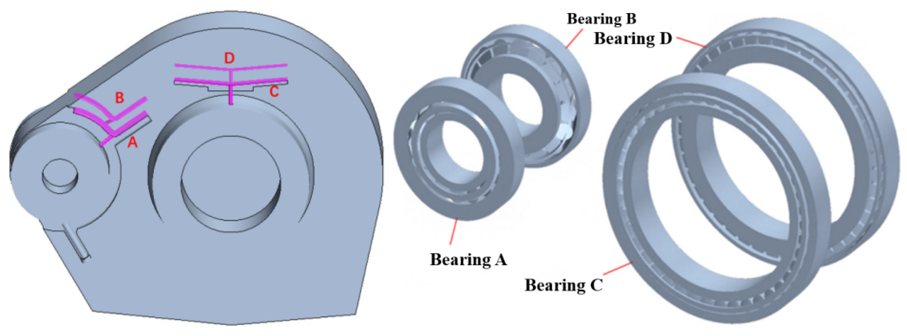
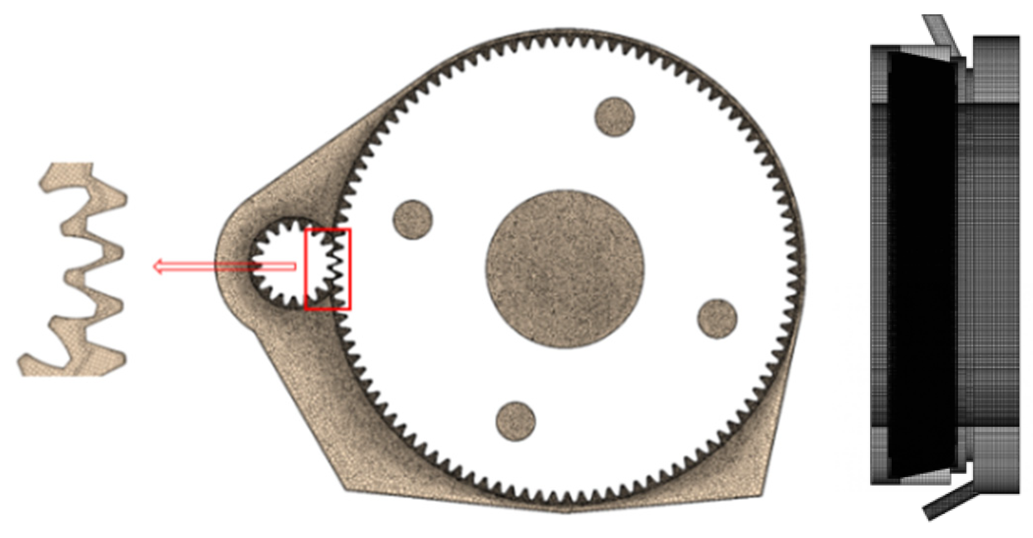
2.1. Geometry
2.2. Meshing
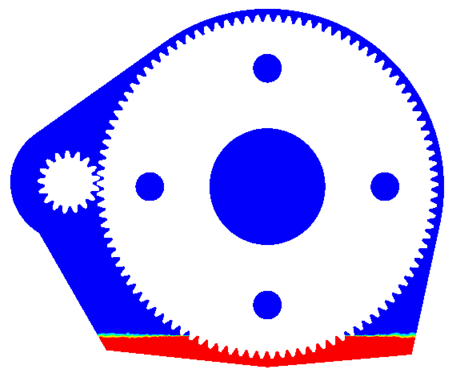
2.3. Boundary Conditions
2.4. Solving Process and Algorithm Optimization
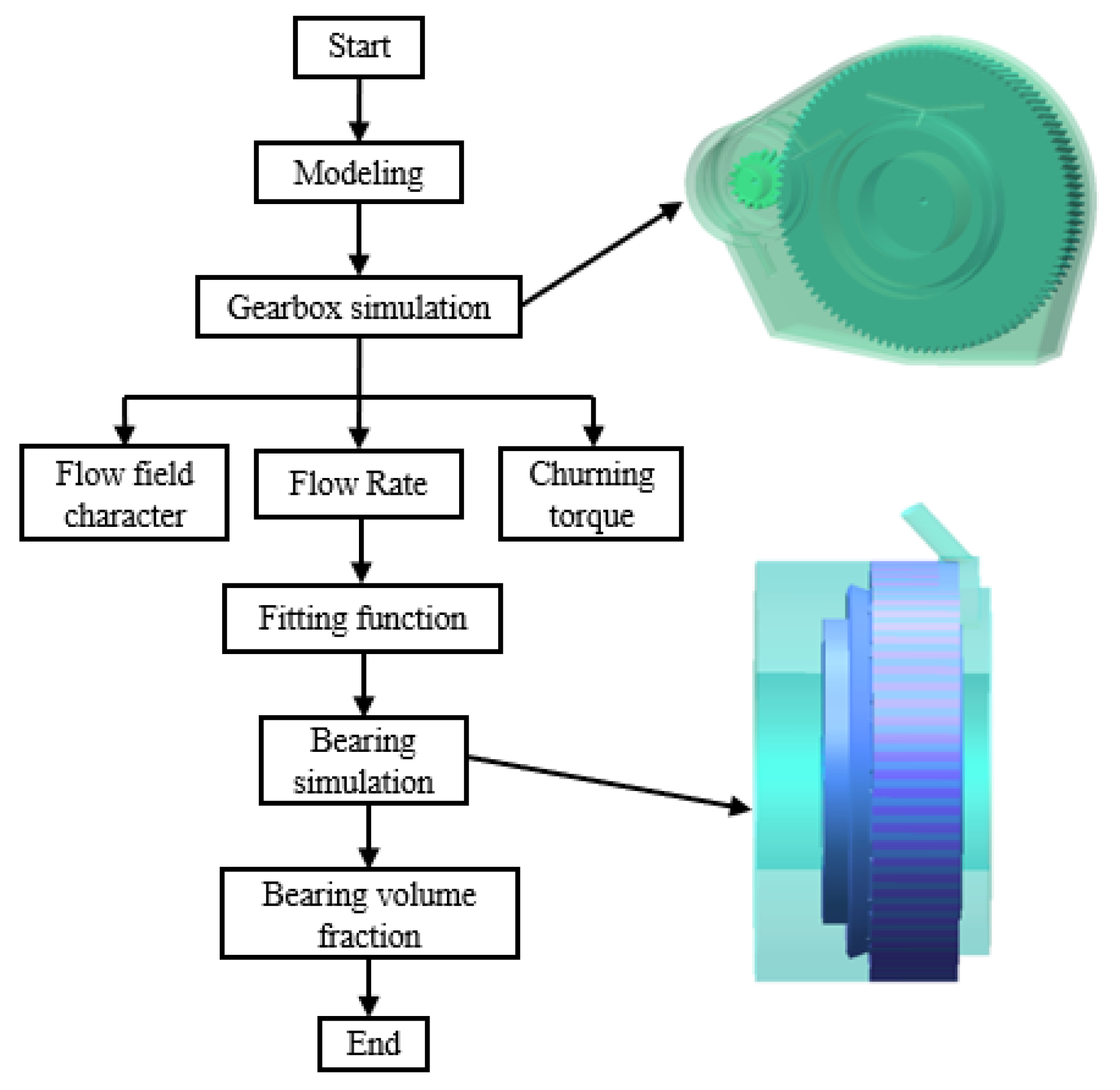
- (1)
- Gearbox Simulation: Determine the flow field characteristics, agitation torque, and flow rates through the oil-guide channels.
- (2)
- Bearing Simulation: Apply the calculated channel flow rates as inlet boundary conditions to analyze the lubricant volume fraction within the bearings.
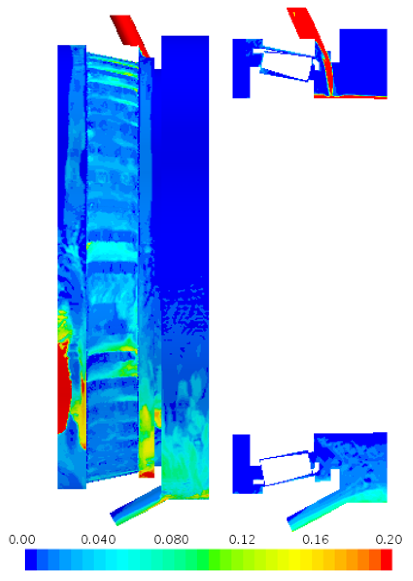
3. Results and Discussion
3.1. Effect of Gear Acceleration
3.2. Effect of Oil Temperature
4. Conclusions
- (a)
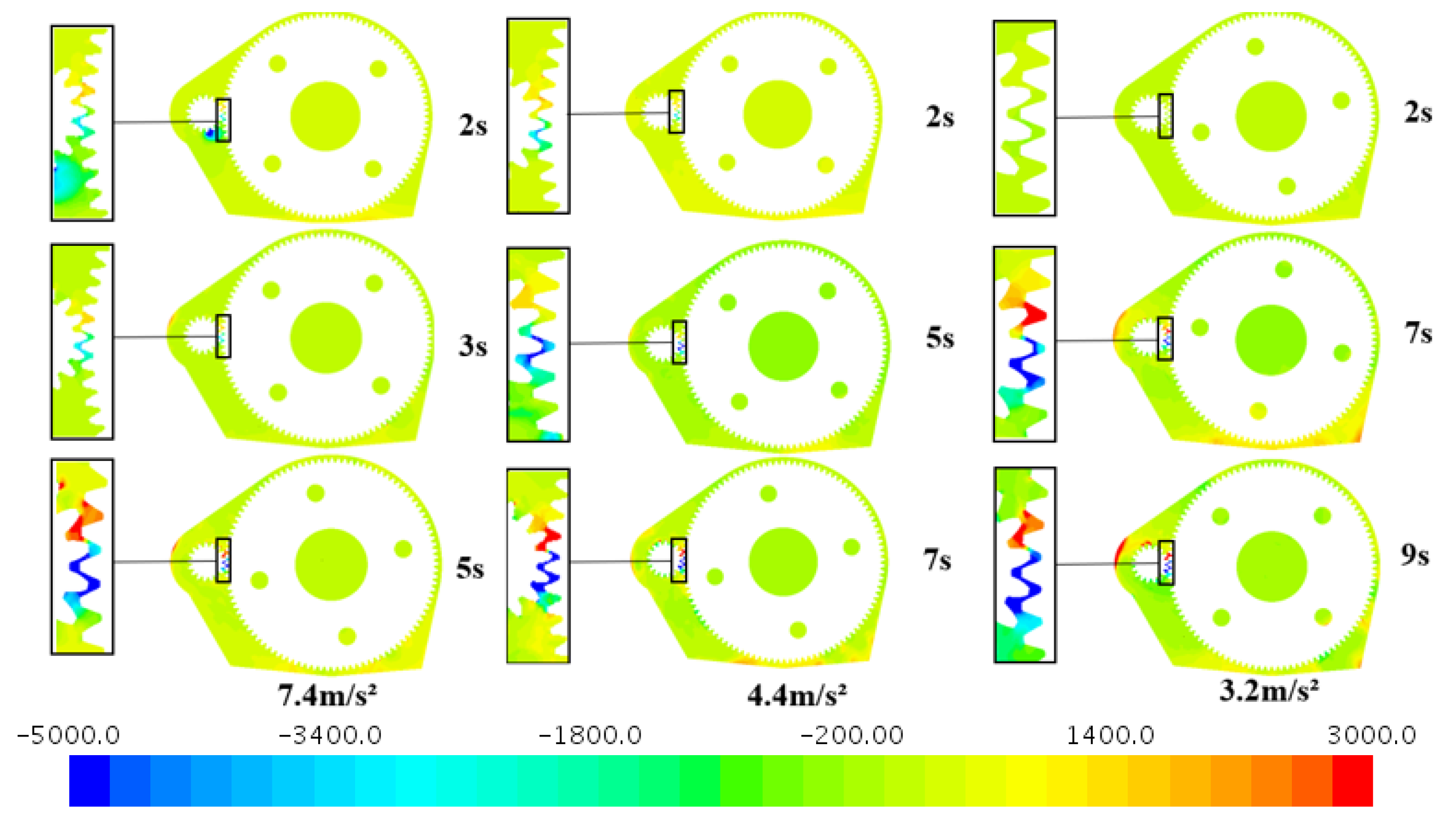
- During acceleration phases, higher gear acceleration (7.4 m/s2 vs. 3.2 m/s2) induces greater initial pressure differentials (3500 Pa vs. 1000 Pa) in gear meshing regions due to rapid lubricant displacement. However, this relationship reverses at steady-state operation, where lower acceleration preserves higher meshing zone pressure (8000 Pa at 3.2 m/s2 vs. 3500 Pa at 7.4 m/s2) through optimized oil retention.
- (b)
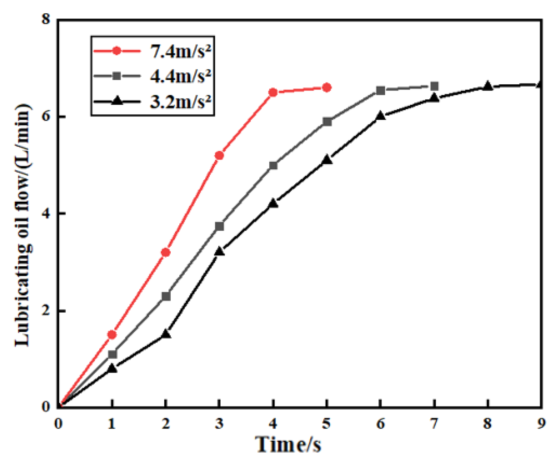
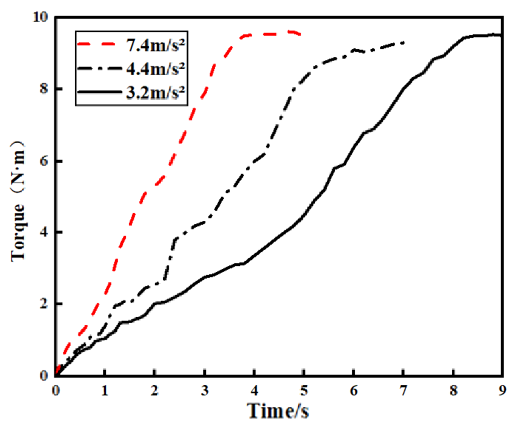
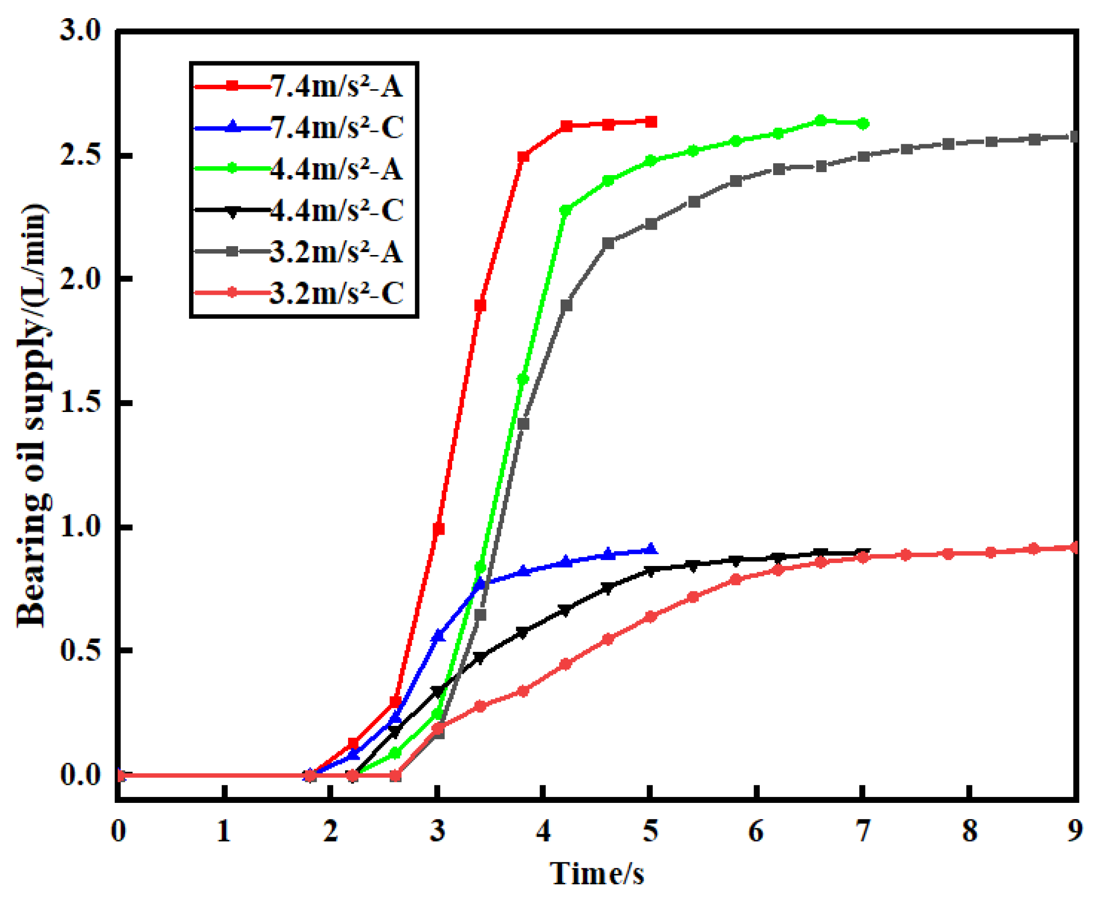
- Higher accelerations enhance transient lubrication efficiency of the gear meshing area and the bearings. However, the steady-state performance of the gear meshing area and the bearings remains consistent across conditions. Therefore, acceleration governs transient dynamics but not equilibrium lubrication.
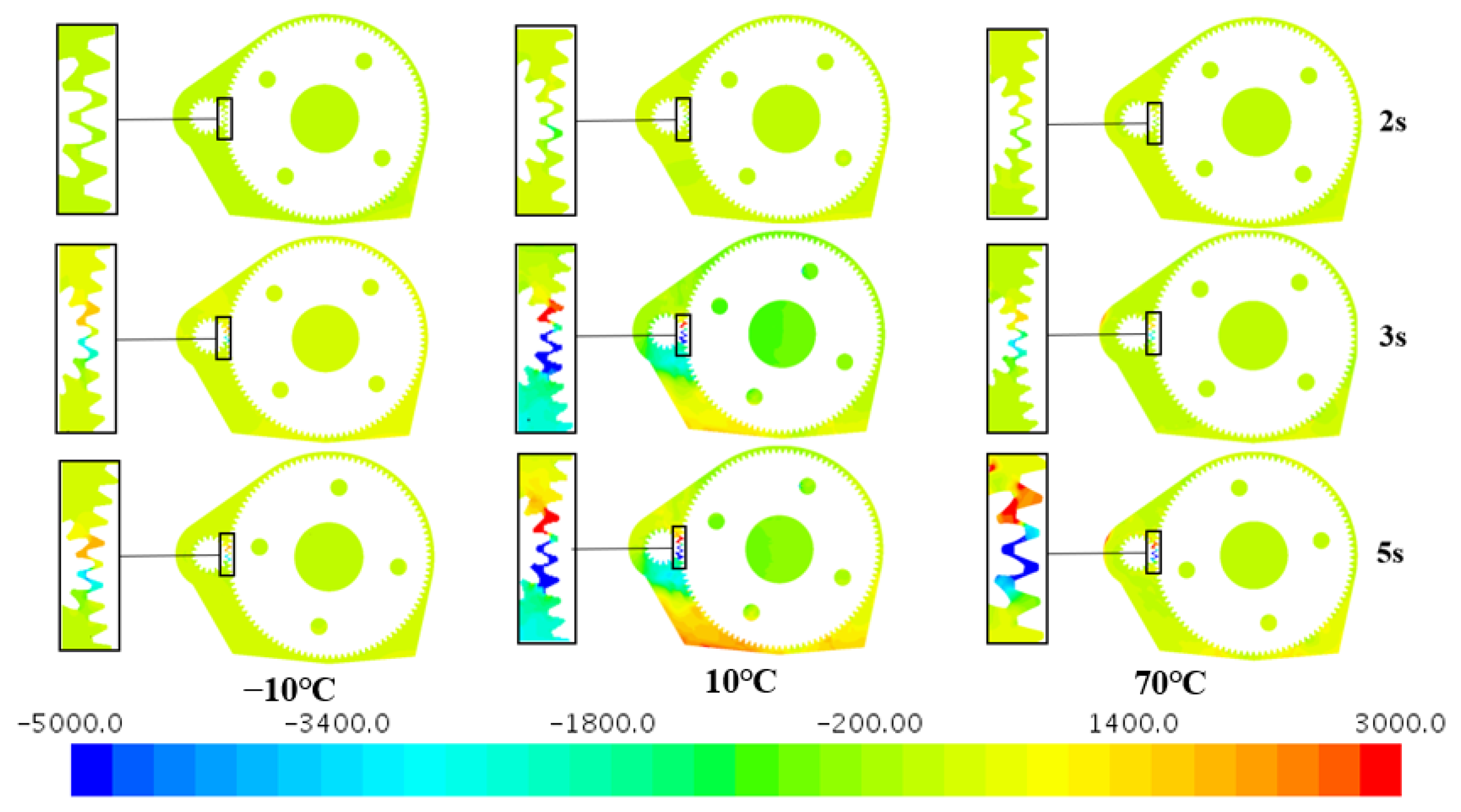
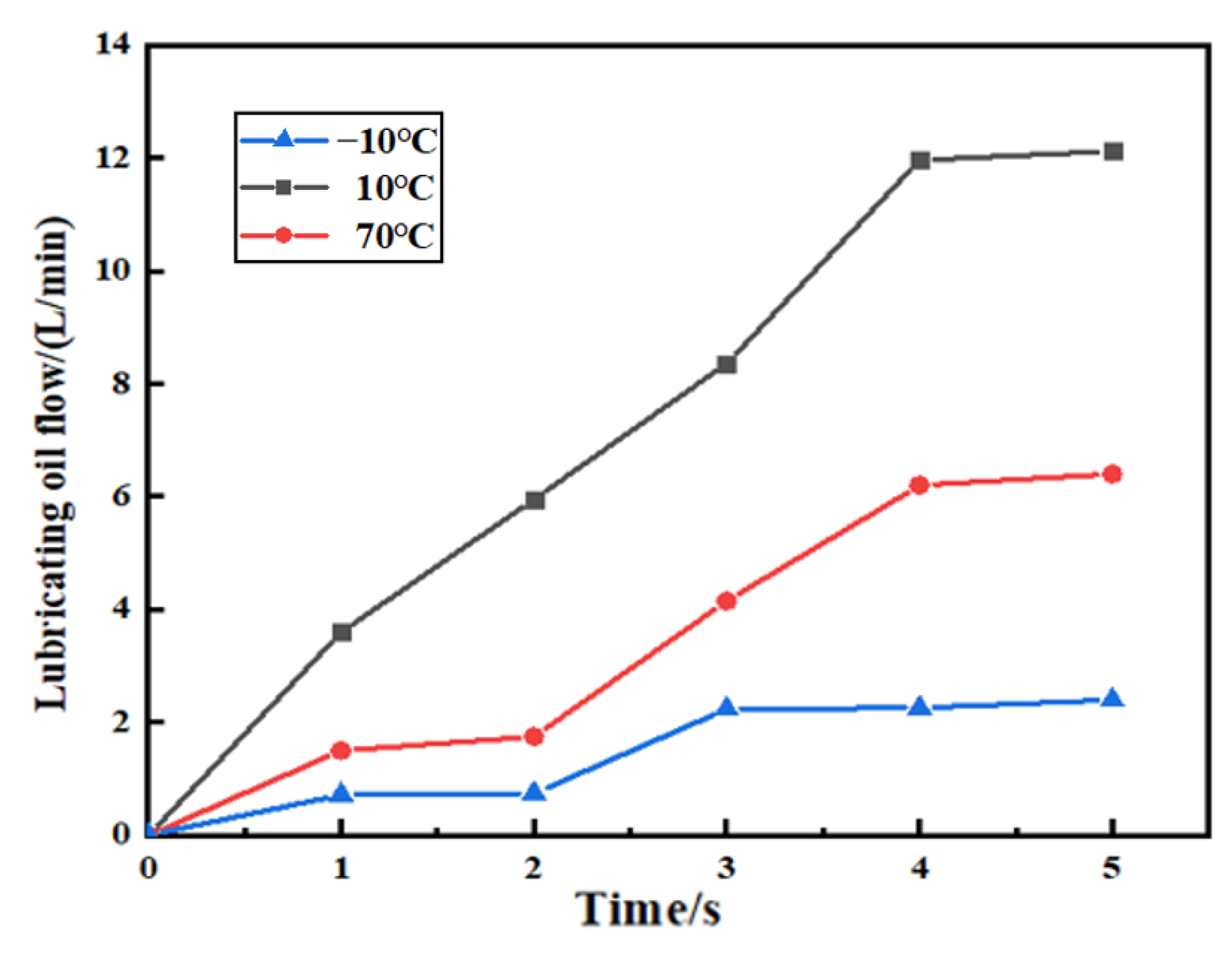
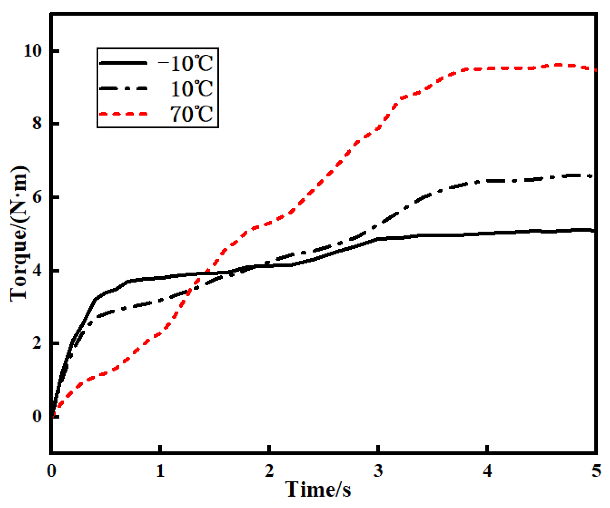
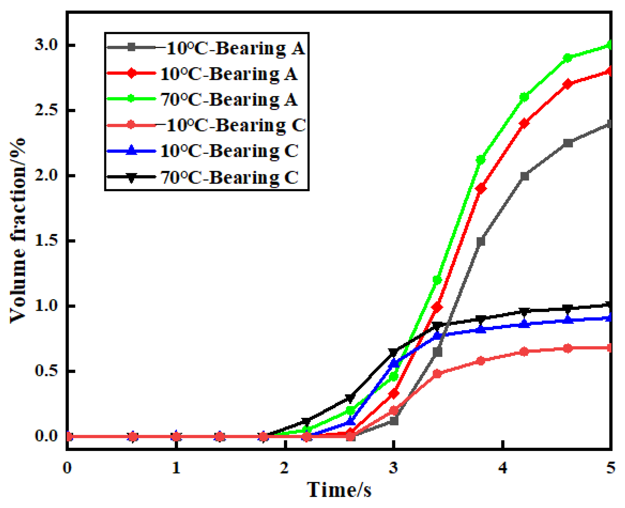
- (c)
- Temperature critically modulates lubrication dynamics, whereby lower temperatures delay oil supply initiation and restrict bearing flow due to high viscosity, while elevated temperatures accelerate distribution but reduce meshing area retention. Optimal meshing oil accumulation occurs at moderate temperatures, balancing viscosity and flow efficiency.
- (d)
- Although oil temperature influences the initial time required for a lubricant to reach bearing lubrication channels, the final arrival time into the bearing interior just slightly decreases across temperature conditions.
Author Contributions
Funding
Data Availability Statement
Acknowledgments
Conflicts of Interest
References
- He, Q.; Li, A.; Zhang, J.; Zhang, J.; Ma, J. The development trendof high speed train bearings. J. Xuzhou Inst. Technol. (Nat. Sci. Ed.) 2012, 27, 58–64. [Google Scholar]
- Yang, S.; Wang, X.; Chen, C.; Liu, S. Research status and trend of gearbox design of high-speed EMUs. Mach. Tool Hydraul. 2021, 49, 173–179. [Google Scholar]
- Luo, Z.; Zhang, H. Failure analysis of transmission gears of gearboxes in metro vehicles. Harbin Railw. Sci. Technol. 2023, 4, 27–31. [Google Scholar]
- Cheng, X. Analysis and treatment of typical faults of Zhengzhou metro vehicle gearbox. Urban Rail Transit Res. 2022, 25, 225–228. [Google Scholar]
- Zhang, L.; Wang, B.; Zhou, L.; Wang, J. Experimental design and analysis of oil stirring loss bench for gear oil stirring loss of oil-immersed lubrication reducer. J. Yancheng Inst. Technol. (Nat. Sci. Ed.) 2024, 37, 67–72. [Google Scholar]
- Laruelle, S.; Fossier, C.; Changenet, C.; Ville, F.; Koechlin, S. Experimental investigations and analysis on churning losses of splash lubricated spiral bevel gears. J. Mech. Ind. 2017, 18, 412. [Google Scholar] [CrossRef]
- Zhu, H.; Zhao, J.; Sun, Q.; Zheng, Q.; Liu, S.; Yin, S.; Zheng, Q.; Huo, Y. Design and study of gearbox splash lubrication test bench. Mech. Des. 2019, 36, 113–116. [Google Scholar]
- Liu, H.; Jurkschat, T.; Lohner, T.; Stahl, K. Detailed Investigations on the Oil Flow in Dip-Lubricated Gearboxes by the Finite Volume CFD Method. Lubricants 2018, 6, 47. [Google Scholar] [CrossRef]
- Liu, H.; Arfaoui, G.; Stanic, M.; Montigny, L.; Jurkschat, T.; Lohner, T.; Stahl, K. Numerical modelling of oil distribution and churning gear power losses of gearboxes by smoothed particle hydrodynamics. Proc. Inst. Mech. Eng. Part J J. Eng. Tribol. 2019, 233, 74–86. [Google Scholar] [CrossRef]
- Stavytskyi, V.; Bashta, O.; Nosko, P.; Tsybrii, Y. Determination of Hydrodynamic Power Losses in a Gearing. Acta Mech. Autom. 2022, 16, 1–7. [Google Scholar] [CrossRef]
- Shao, S.; Zhang, K.; Yao, Y.; Liu, Y.; Gu, J. Investigations on lubrication characteristics of high-speed electric multiple unit gearbox by oil volume adjusting device. J. Zhejiang Univ.-Sci. A 2022, 23, 1013–1026. [Google Scholar] [CrossRef]
- Shen, L.; Zhu, Y.; Shao, S.; Zhou, H.; Wang, Z. Research on Splash Lubrication Characteristics of a Spiral Bevel Gearbox Based on the MPS Method. Lubricants 2023, 11, 520. [Google Scholar] [CrossRef]
- Wang, Z.; Guo, L.; Zhou, Z.; Guo, R.; Zhu, L. Flow field analysis and optimization of oil guide structure of metro gearbox splash lubrication. J. Railw. Sci. Eng. 2025, 1–12. [Google Scholar] [CrossRef]
- Ma, Y.; Zhan, D.; Liu, J. Improvement of gearbox lubrication structure based on SPH algorithm. Constr. Mach. 2022, 53, 27–33+8. [Google Scholar]
- Hu, X.; Li, P.; Wu, M. Influence of the Dynamic Motion of a Splash-Lubricated Gearbox on Churning Power Losses. Energies 2019, 12, 3225. [Google Scholar] [CrossRef]
- Hu, X.; Jiang, Y.; Luo, C.; Feng, L.; Dai, Y. Churning power losses of a gearbox with spiral bevel geared transmission. Tribol. Int. 2019, 129, 398–406. [Google Scholar] [CrossRef]
- Liu, Y.; Zhang, K.; Shao, S.; Xiang, H.; Ye, Z. Influence of vibration on the lubrication effect of a splash-lubricated gearbox. J. Zhejiang Univ.-Sci. A 2024, 25, 324–339. [Google Scholar] [CrossRef]
- Hildebrand, L.; Dangl, F.; Sedlmair, M.; Lohner, T.; Stahl, K. CFD analysis on the oil flow of a gear stage with guide plate. Forsch Ingenieurwes 2022, 86, 395–408. [Google Scholar] [CrossRef]
- Lu, F.; Wei, K.; Wang, M.; Li, M.; Bao, H. Oil film deposition characteristics and judgment of lubrication effect of splash lubricated gears. J. Mech. Sci. Technol. 2023, 37, 2383–2393. [Google Scholar] [CrossRef]
- Liu, H.; Jurkschat, T.; Lohner, T.; Stahl, K. Determination of oil distribution and churning power loss of gearboxes by finite volume CFD method. Tribol. Int. 2017, 109, 346–354. [Google Scholar] [CrossRef]


Disclaimer/Publisher’s Note: The statements, opinions and data contained in all publications are solely those of the individual author(s) and contributor(s) and not of MDPI and/or the editor(s). MDPI and/or the editor(s) disclaim responsibility for any injury to people or property resulting from any ideas, methods, instructions or products referred to in the content. |
© 2025 by the authors. Licensee MDPI, Basel, Switzerland. This article is an open access article distributed under the terms and conditions of the Creative Commons Attribution (CC BY) license (https://creativecommons.org/licenses/by/4.0/).
Share and Cite
Wang, Z.; Guo, L.; Li, X.; Wu, F.; Ye, J. An Analysis of Flow Field Characteristics Under the Start-Up Condition of a Subway Gearbox. Lubricants 2025, 13, 220. https://doi.org/10.3390/lubricants13050220
Wang Z, Guo L, Li X, Wu F, Ye J. An Analysis of Flow Field Characteristics Under the Start-Up Condition of a Subway Gearbox. Lubricants. 2025; 13(5):220. https://doi.org/10.3390/lubricants13050220
Chicago/Turabian StyleWang, Zhijian, Liwei Guo, Xinglin Li, Feng Wu, and Jianguo Ye. 2025. "An Analysis of Flow Field Characteristics Under the Start-Up Condition of a Subway Gearbox" Lubricants 13, no. 5: 220. https://doi.org/10.3390/lubricants13050220
APA StyleWang, Z., Guo, L., Li, X., Wu, F., & Ye, J. (2025). An Analysis of Flow Field Characteristics Under the Start-Up Condition of a Subway Gearbox. Lubricants, 13(5), 220. https://doi.org/10.3390/lubricants13050220