Article

Analytical Method for Predicting Wear Life of Angular Contact Ball Bearings Under Variable Loading Based on Mixed Lubrication

1
School of Mechanical Engineering, Chongqing Industry Polytechnic College, Chongqing 401120, China
2
School of Mechatronics and Vehicle Engineering, Chongqing Jiaotong University, Chongqing 400074, China
*
Author to whom correspondence should be addressed.
Lubricants 2025, 13(5), 212; https://doi.org/10.3390/lubricants13050212
Submission received: 25 March 2025 / Revised: 5 May 2025 / Accepted: 9 May 2025 / Published: 12 May 2025
(This article belongs to the Special Issue Tribological Characteristics of Bearing System, 3rd Edition)

Abstract

:
In aerospace technology, angular contact ball bearings are required to exhibit extremely high operational precision, necessitating real-time monitoring of their wear status to conduct pre-failure analysis. Although extensive studies have been conducted on the wear characteristics of angular contact bearings, further in-depth research is still required to enhance the accuracy of bearing life predictions. To address the imprecision in wear life prediction for angular contact ball bearings, this article proposes a refined wear calculation model based on dynamic load distribution. The model calculates the dynamic load distribution between the inner and outer rings and the raceway under mixed lubrication conditions. Integrating the dynamic load distribution methodology with the wear calculation model, the dynamic contact characteristics of angular contact bearings can be more accurately characterized. Building on this foundation, a dynamic analysis model considering dynamic wear in the bearing contact zone is established. The vibration characteristics of bearings under varying loads are analyzed, and vibration experiments under different load conditions are conducted. Through vibration spectrum analysis, the influence patterns of wear characteristic frequency bands in the wear model on the pre-failure state of bearings are further elucidated. This study provides a theoretical basis for bearing wear life prediction analysis.

1. Introduction

According to relevant data, approximately 30% of the failures and faults occurring in mainframe systems can be attributed to the malfunction of rolling bearings [1]. Therefore, this study focuses on performing pre-failure analysis specifically for angular contact ball bearings used in spatial transmission mechanisms. To date, many researchers have conducted a large number of theoretical studies on the life prediction of angular contact ball bearings. Lundberg and Palmgren [2] proposed the L-P life theory—a model for calculating the fatigue life of rolling bearings—by applying statistical methods to derive patterns from a large amount of data based on the Weibull theory. This model is often used to predict bearing fatigue life but, for improved materials, the prediction results are far less than the actual life. To overcome the limitations of the L-P model, Ioannides and Harris further developed the I-H model [3]. Subsequently, Zaretsky et al. [4] modified the L-P model by neglecting the influence of crack initiation depth on the calculation and changing the critical stress from orthogonal shear stress to maximum shear stress. Subsequently, numerous studies on rolling bearing contact fatigue have emerged.
Deolalikar and Sadeghi [5] employed a modified I-H life model to investigate the variation trend of fatigue life of point contact mixed lubrication under different external working condition parameters and roughness parameters. Gabelli et al. [6] proposed a fatigue life theory that considers both surface and subsurface origins in response to the phenomenon that the fatigue life of ceramic ball bearings, based on the subsurface-initiated contact theory, does not decrease but rather increases compared to that of general rolling bearings. Ghaffari [7] presented a multiscale rolling contact fatigue life analysis that takes into account lubrication effects and investigated the influence of fluctuating loads on rolling contact fatigue life. Sesana [8] developed a bearing fatigue life model that considers the micro-inclusion effect of materials and analyzed the impact of micro-inclusions on bearing fatigue life.
In recent years, some studies have found that the crack initiation process of fatigue life is related to the lubrication conditions of bearings [9,10,11,12,13], especially under severe operating conditions, where the inadequate lubrication of contact surfaces has a significant impact on the service life of moving components [14]. Therefore, in recent years, numerous studies [15,16] have specifically analyzed the lubrication characteristics of rolling bearings. With the continuous advancement of bearing material properties and processing technologies, fatigue failure is no longer the primary constraint on bearing performance [17]. Instead, the complex rotation–sliding–rolling motion within the micro-contact zones of bearing systems frequently induces frictional spalling of surface materials, resulting in a loss of the original operating accuracy of the bearings [18]. Furthermore, the combination of multiple motion modes can lead to a decrease in the effectiveness of lubrication, potentially exacerbating wear failure in bearing materials.
Park [19] proposed a rapid calculation method for wear on contact surfaces during the operation of transmission mechanisms. This method employs a special single-grid superposition approach to calculate the distribution of lateral and tangential forces at each grid point, thereby estimating the wear amount on the contact surface more accurately. Lai [20] studied the wear mechanism of solid lubricating bearings in a vacuum environment and the wear of bearings through experiments, analyzing the relationships between wear and time and temperature and vibration amplitude. Jamari’s [21] proposed model for predicting wear behavior, the global incremental wear model (GIWM), shows high accuracy. An analytical general model for incremental prediction of fretting wear depth and volume evolution was developed by Cura et al. [22]. The model demonstrates significantly improved prediction accuracy for incremental wear depth and volume on contact interfaces operating under misalignment conditions. Cubillas [23] proposed a semi-analytical method for fretting damage areas of angular contact ball bearing raceways under variable loads. It reflects the fact that the small reciprocal movements in the bearings can cause wear damage at the contact between the rolling elements and the raceway, thus affecting the accuracy of the operation. Zhang [24] proposed a dynamic wear simulation model to study the preload changes caused by different preloading methods on bearing wear life due to the influence of load changes on wear. A new dynamic wear simulation model for paired angular contact ball bearings was proposed by Gu et al. [25], and the effects of operating distance, horizontal load, preload, initial contact angle, and number and diameter of balls on wear characteristics were investigated. Jang and Khonsari [26] established a computational model for predicting engine bearing wear based on the principle of mass conservation, taking into account lubrication, and analyzed the impact of shaft alignment on bearing wear.
Analyzing the wear investigations of angular contact ball bearings reported in the above studies, it was found that they conduct bearing wear or life studies with wear calculation methods, or lubrication and variable load influence factors, respectively. However, the influence of dynamic load distribution on bearing wear life has not been considered. Additionally, the influence of mixed lubrication regimes under real operating conditions has not been adequately considered in existing studies.
In this study, a wear calculation model considering dynamic load distribution and mixed lubrication is established to predict the operation of angular contact ball bearings. Firstly, a wear prediction model is established based on Hertzian contact theory and dynamic load analysis of angular contact bearings. Subsequently, the oil film thickness and pressure distribution in mixed lubrication regimes of angular contact bearings are analyzed, and the wear model is modified considering lubrication effects. On this basis, a dynamic analysis model for rolling bearings is developed to solve vibration responses under varying loads. Finally, experimental validation is conducted to verify the accuracy of the proposed models. Employing the wear-integrated dynamic analysis model, the amplitude/frequency characteristics of bearing vibration signals over time can be obtained, enabling the prediction of vibration signatures during wear-induced failures and thus enabling lifespan prediction for angular contact bearings.

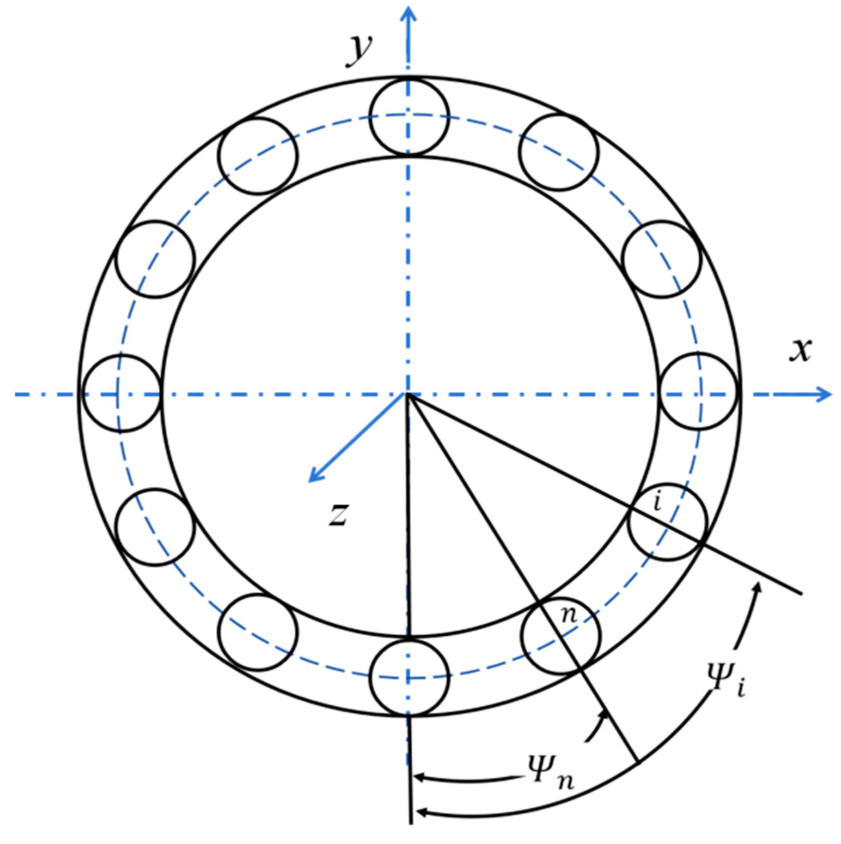
2. Optimized Dynamic Load Distribution Calculation Method

Combined with the actual operation state of the angular contact ball bearing, the load of each ball is changed at different times. Therefore, according to kinematics theory, it is necessary to establish the dynamic load distribution between the ball and the raceway to calculate the wear and life between them more accurately [27]. The following essential assumptions are adopted in this study: only the interaction between the inner ring, outer ring, and raceway of the bearing is considered, while the influence of the cage component on the bearing kinematics is neglected; manufacturing and assembly errors of the bearing are ignored, as are the effects of frictional heat and material hysteresis characteristics at the contact surfaces on the kinematic and mechanical behavior.
Assuming that only radial load is considered for bearings, and according to the geometric relationship shown in Figure 1, the load on the contact surface of angular contact ball bearings is calculated as follows [28]:
Q ψ = Q max 1 1 2 T 1 cos ψ 1 / T
where Q ψ is the ball/raceway contact load when the contact angle is located at ψ ; Q max is the maximum load of the ball/raceway contact surface; T is the coefficient of load distribution (according to Ref. [29], T = 3 / 2 ).
The above expression only considers the load under motion but does not establish a theoretical model for the distribution of dynamic load. In the following, the calculation of load distribution changes during the operation of angular contact ball bearings will be considered.
We assume that the stress distribution on the contact surface of the angular contact ball bearings is calculated as follows [30]:
1 π E S c p x , y d x d y x x 2 + y y 2 = δ z x , y
where E is the integrated material elastic modulus; δ is the elastic approach of local coordinate point ( x , y ) ; p ( x , y ) is the loading value of coordinate point ( x , y ) ; z x , y is the initial distance of the surface when there is no contact.
According to the calculation method of the traditional contact surface [31], the relationship between the elastic approach and the load of the contact surface is δ = K Q t , where K can be expressed as
K = 2 K e π 1 e 2 π 2 E e 1 / 3 3 2 ρ E 2 / 3 ρ 2
where e is the elliptical parameter; K e is the elliptical parameter of the first kind; E e is the elliptical parameter of the second kind; ρ is the integrated radius of curvature of the contact surface.
In the actual operation of bearings, the ratio of the elastic approach of the inner and outer rings of the ball at different positions is different [32]:
δ ψ 1 δ ψ 2 = 1 1 2 T 1 cos ψ 1 1 1 2 T 1 cos ψ 2
where ( ψ 1 , ψ 2 ) are the contact angles when the ball is in different positions.
Combined with the above equation, the relationship between the contact load of the ball at two different positions in the ball/raceway contact surface can be calculated:
Q n = Q i 1 1 2 T 1 cos ψ n 1 1 2 T 1 cos ψ i 1 / t
The sum of the load on the ball of the bearing under the radial force is as follows:
F r = Q 1 cos ψ 1 + Q 2 cos ψ 2 + + Q z cos ψ z = n = 1 z Q n cos ψ n
where Z is the number of balls; Q 1 , Q 2 , , Q n is the load of different balls; ψ 1 , ψ 2 , , ψ n is the angle between the force direction and the external force between the different balls and the raceway.
Equation (5) is substituted into Equation (6) to obtain the following equation:
F r = Q i n = 1 Z c n 1 1 2 T 1 cos ψ n 1 1 2 T 1 cos ψ i 1 / t cos ψ n
Different balls may not be loaded at some time, and the actual contact load of the balls [33] is as follows:
Q i = F r 1 1 2 T 1 cos ψ i 1 / t n = 1 Z c n r 1 1 2 T 1 cos ψ n 1 / t cos ψ n
If the ball is stressed, cn = 1; otherwise, cn = 0. Equation (8) calculates the force between the ball and the raceway at different positions in detail.
The rated contact dynamic load of the contact zone of the inner and outer rings of the bearing can be calculated as
Q c = 98.1 2 f n 2 f n 1 0.41 1 γ 1.39 1 ± γ 1 / 3 γ cos α 0.3 D b 1.8 Z 1 3
where symbols in the first column are used for the inner ring, and symbols in the second column are used for the outer ring; n = i , e , f i , f e are groove curvature radius coefficients of the inner and outer raceway; γ = D b cos α / D m .
Through Hertz, the drag of each point (x, y) in the contact area is calculated as [34]
p n ( x , y ) = 3 Q c 2 π a b [ 1 x 2 a 2 y 2 b 2 ] 1 / 2 x , y C
where a is the contact ellipse major semi-axes; b is the contact ellipse minor semi-axes.

3. A Calculation Method of Wear Based on the Dynamic Load Distribution and Archard Model Considering Mixed Lubrication

Based on the rolling contact theory of angular contact ball bearings, the dynamic load distribution of the contact surface between the ball and the inner and outer rings can be calculated with reference to the mechanical characteristics [35].

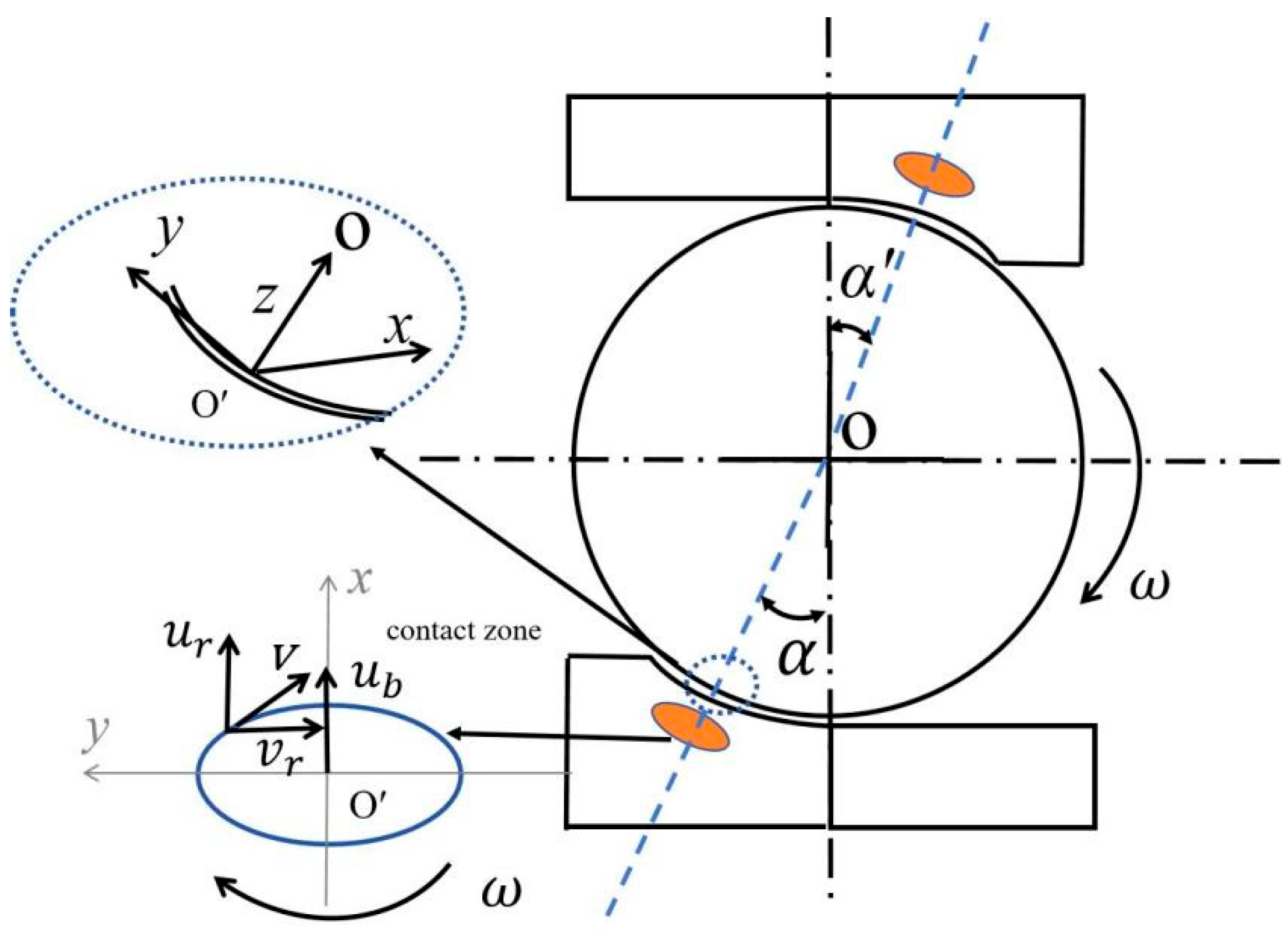
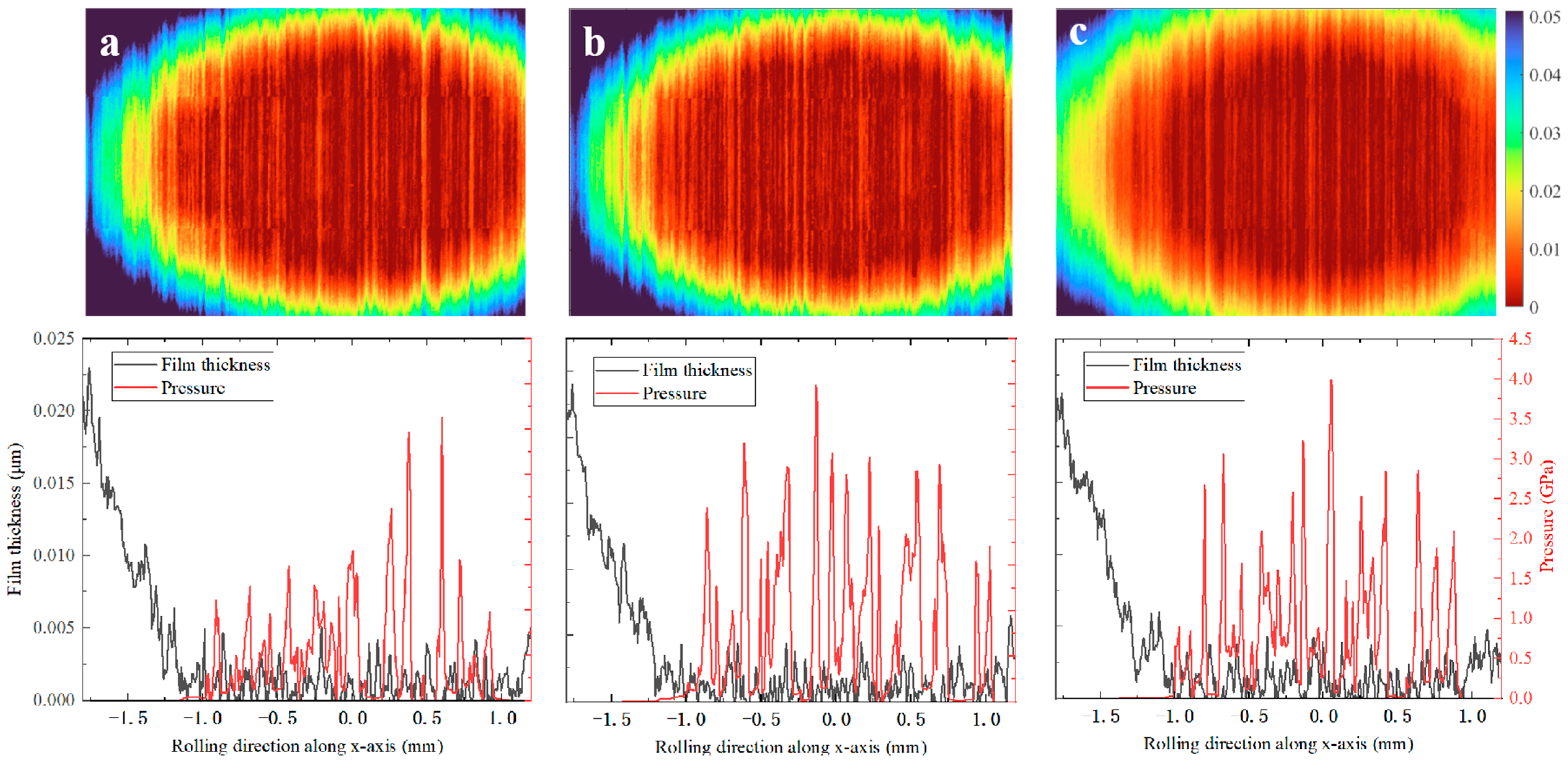
3.1. Contact Stress Distribution Model

The force at each point of the contact ellipse has been established, and the rated dynamic load of the inner and outer rings can be calculated as follows:
Q c = 77.86 2 f n 2 f n 1 0.41 1 γ 1.39 γ cos α 0.3 D b 1.8
Similarly, the basic rated dynamic load of the rolling ball and the inner and outer raceways is as follows:
Q cb = 77.86 2 f n 2 f n 1 0.41 1 γ 1.69 D b 1 . 8 cos α 0.3
where the negative sign is used for the rated dynamic load of the inner ring and the positive sign is used for the rated dynamic load of the outer ring; f n is the coefficient of groove curvature radius of the inner or outer ring.
If the inertia and rotation of the ball during operation are considered, the equivalent load of the ball is calculated as follows:
Q eb = 1 2 π Q b n 3 ψ d ψ 1 / 3
If Q b n = Q b i , Equation (13) is the equivalent load between the ball and the inner ring; if Q b n = Q b e , Equation (13) is the equivalent load between the ball and the outer ring.

3.2. Wear Depth Calculation Model Under Mixed Lubrication State

The relationship between the contact and motion of the rollers and raceways in angular contact bearings is as shown in Figure 2.
When conducting lubrication analysis, the lubrication pair between the rollers of angular contact bearings and the inner and outer raceways can be equivalently modeled as contact between an ellipsoid and an infinitely large plane. The motion of the lubrication pair can be equivalently modeled as a rolling body moving on an infinitely large plane at an average velocity of ub, which is the mean velocity between the inner and outer raceways. Simultaneously, the plane rotates with a spin angular velocity of ω. The velocity components at any point in the contact area are vr and ur, respectively.
u r ( x , y ) = ω y / 2 + u b v r ( x , y ) = ω x / 2
For mixed elastohydrodynamic lubrication (EHL), a full numerical solution can be obtained by referring to reference [36], with the governing equations given in Appendix A.
Previously, researchers proposed the Archard wear model [14]. To date, some researchers still apply the Archard wear model to the friction and wear between objects. In this model, it is necessary to solve for the value of the contact area. By corresponding to the load on the contact surface, the wear value is calculated based on its wear volume as follows:
d V d L = 2 3 π a 3 / 2 a = Q 3 σ s
where V is the wear volume; L is the sliding distance; σ s is the yield limit.
From Equation (15), it is evident that the wear value of the contact surface is directly proportional to the contact distance and normal force. If the normal force remains unchanged, the smaller the σ s , the deeper the degree of wear.
ω h = K Q H
where K is the coefficient of adhesion wear; H is the Brinell hardness.
We know that Q v = p v d x d y = 1.5 F π a b ; the following equation can be obtained from Equations (10) and (16):
ω h = K H 3 Q 2 π a b a a b [ 1 x / a 2 ] 1 2 b [ 1 x / a 2 ] 1 2 1 x / a 2 y / a 2 1 2 × y ω s 2 + x ω s + V d 2 d x d y
In real operating conditions, not all the asperities are in contact due to the presence of lubricants. Therefore, the wear needs to be corrected, and the above equation can be rewritten as
ω h = λ K H 3 Q 2 π a b a a b [ 1 x / a 2 ] 1 2 b [ 1 x / a 2 ] 1 2 1 x / a 2 y / a 2 1 2 × y ω s 2 + x ω s + V d 2 d x d y

3.3. Vibration Equation Considering Wear

In the normal work of angular contact ball bearings, the long-term contact between the ball and the raceway is affected by its contact load, and its wear value will change at different time periods, thus affecting its accuracy [17]. Assuming that the structural parameters of the bearing are fixed and the contact load and deformation between ball and raceway under radial load have the same effect, Kn denotes the deformation coefficient, and the expression between the contact deformation ( δ ¯ ) and the contact load ( Q ¯ ) is easily obtained as
Q ¯ = K n δ ¯ 3 / 2
If considering the relationship between wear depth and deformation during actual work, it is necessary to consider the differences in deformation at various positions between each ball and raceway. We assume that the total deformation of the j ball is specified as
δ j ( t ) = δ ¯ + Δ δ j ( t )
where δ ¯ is the state deformation; Δ δ j ( t ) is the actual total deformation.
Equation (19) provides a calculation method for the deformation of each ball and then adds the deformation at different positions to the vibration signal. The improved deformation is shown in Equation (20), where ω h is the wear value:
δ j ( t ) = δ ¯ + ω h t
Combining Equations (19) and (21), the relationship between contact load and wear is calculated as
Q ¯ j = K n ( δ ¯ + ω h t ) 3 / 2
The Taylor expansion of Equation (22) provides the following:
Q ¯ j = K n δ 3 / 2 + 3 2 K n δ 1 / 2 ω h t
The excitation torque caused by the contact load of the bearing is calculated as
F r x ( t ) = j = 0 Z 1 Q j ( t ) cos α cos ψ j F a z ( t ) = j = 0 Z 1 Q j ( t ) sin α M x x ( t ) = 1 2 d m j = 0 Z 1 Q j ( t ) sin α cos ψ j
By substituting Equation (23) into Equation (24), the torque of the contact load considering wear factors can be obtained as
F rxw t = j = 0 Z 1 3 2 K n δ 1 / 2 ω n t cos α cos ψ j F axw t = j = 0 Z 1 3 2 K n δ 1 / 2 ω n t sin α M xxw t = 1 2 d m j = 0 Z 1 3 2 K n δ 1 / 2 ω n t sin α cos ψ j
When converting the local coordinate system of Formula (25) torque formula to an inertial coordinate system, the torque is calculated as
F r w ( t ) = 3 2 K n δ 1 / 2 ω h t cos α j = 0 Z 1 cos ψ j ( cos ω c t sin ω c t ) F a w ( t ) = 3 2 Z K n δ 1 / 2 ω h t sin α M w ( t ) = 3 4 d m K n δ 1 / 2 ω h t sin α j = 0 Z 1 cos ψ j ( cos ω c t sin ω c t )
In this study, a three-degrees-of-freedom dynamic model is adopted, as shown in Figure 3. The outer ring is fixed and the inner ring rotates, while the mass and moment of inertia of the bearing are denoted by m and I, and the angular position is denoted by θ. The bearing base is supported by a pair of spring-damping elements, with kx and cx representing stiffness and damping in the x-direction, and ky and cy representing stiffness and damping in the y-direction. These elements represent the supporting effect of the shaft and bearing on the gear. As torsion needs to be considered, the torsional stiffness kθ and torsional damping cθ of the support shaft must also be included in the overall dynamics system. Assuming an external load F is applied, the following set of equations can be obtained based on Figure 3:
M q ¨ + C q ˙ + K q = F
The detailed expressions of M, C, K, and F in the above equations are provided in Appendix B.

4. Calculation Results and Analysis

The angular contact ball bearing SKF 7218B (SKF Group, Gothenburg, Sweden) is used as an example, and the bearing parameters are shown in Table 1.

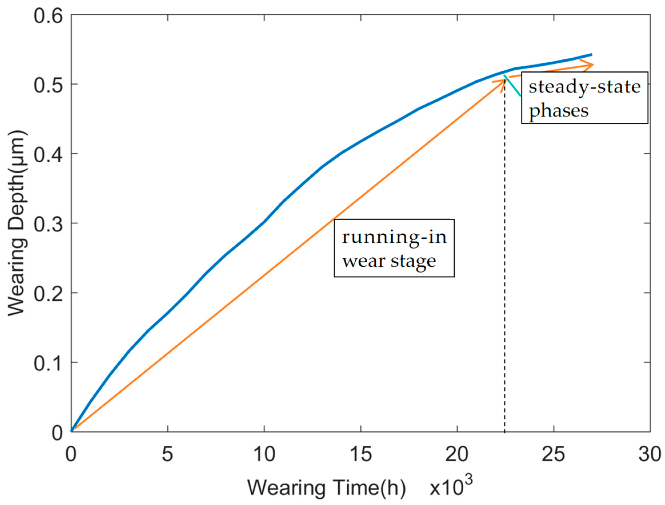
4.1. Wear Analysis of Angular Contact Ball Bearings

When the initial radial force of 5000 N and the rotational speed of 6000 r/min are determined, the transient film thickness distribution considering wear can be obtained. Figure 4 depicts the film thickness and pressure distribution within the bearing roller contact zone during the early-, mid-, and final-stage periods.
Based on the obtained mixed lubrication film thickness and pressure distribution, the bearing roller wear is calculated using the modified wear formula. As shown in Figure 5, as the wear time increases, the wear depth gradually increases, but the growth rate shows a decreasing trend. Due to the increase in wear depth and thinning of the lubricating film during the wear process, the compression deformation between the ball and the groove decreases, the contact load decreases, and the wear rate decreases accordingly. As the wear time increases, the contact load gradually decreases and the wear rate decreases, resulting in a slower growth rate of wear depth. Therefore, although the wear time increases, the growth rate of wear depth decreases. This phenomenon clearly illustrates the transition of the bearing from the running-in wear stage to steady-state operation, as depicted in Figure 5.

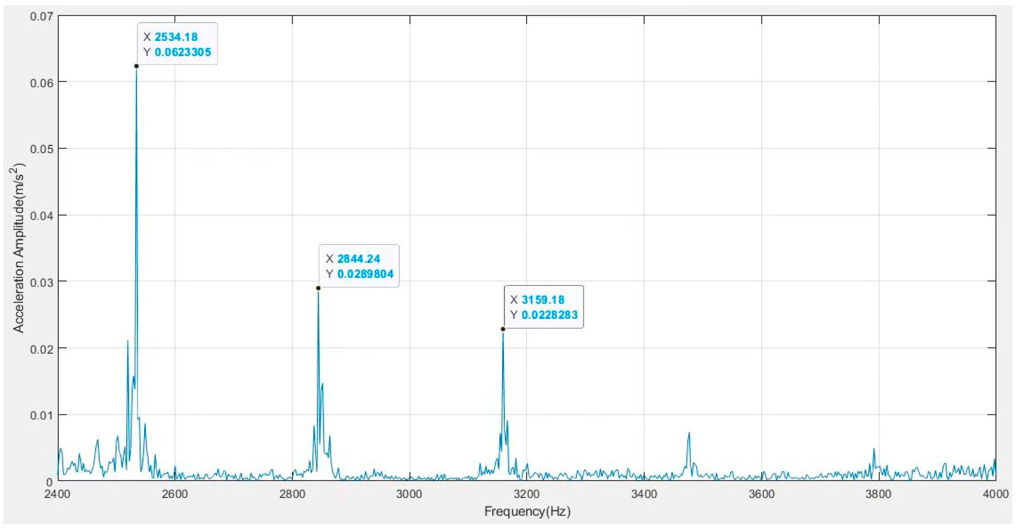
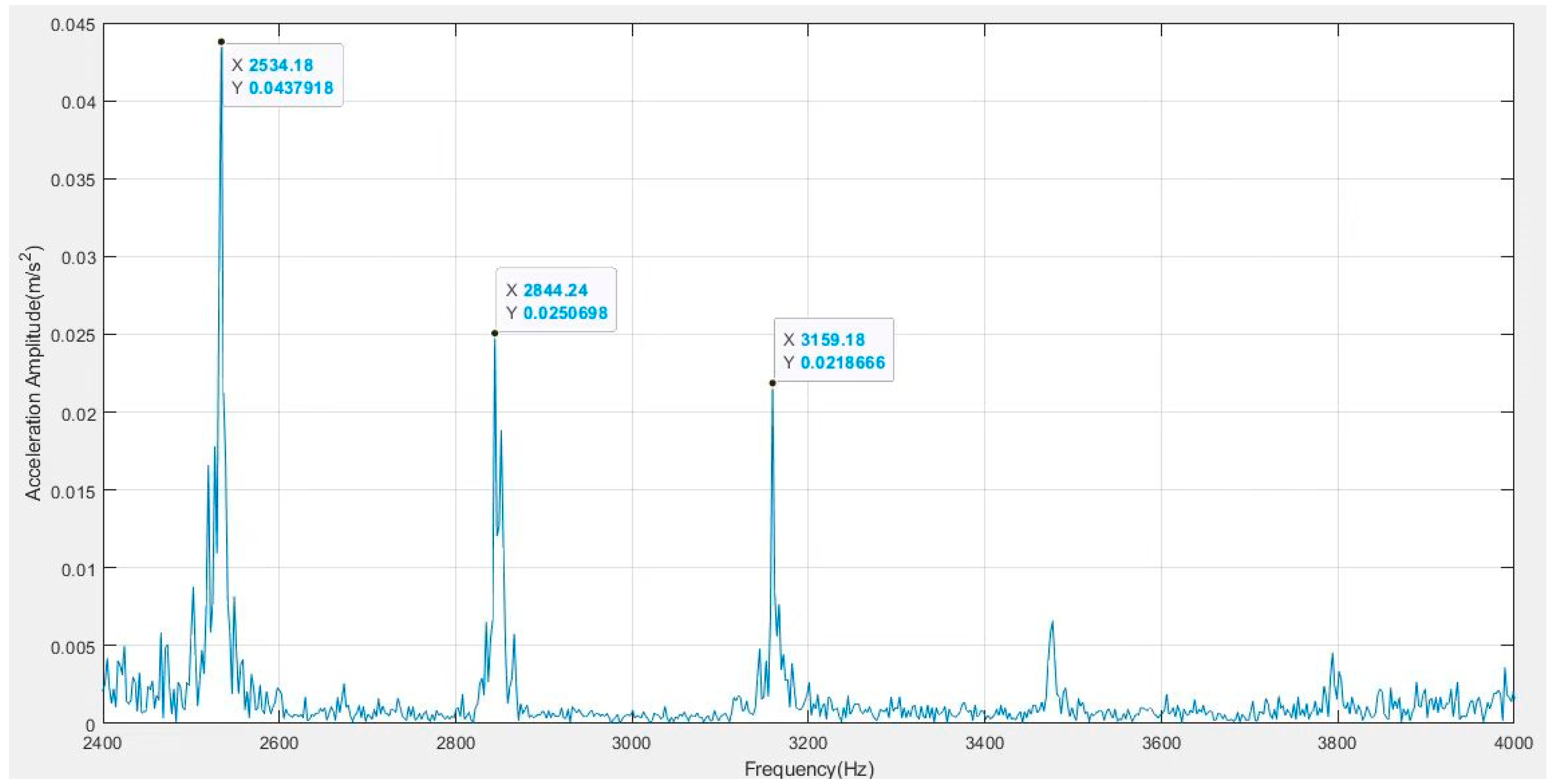
4.2. Spectral Analysis of Acceleration of Bearings

Equation (27) is a non-homogeneous second-order linear differential equation describing the vibration of an angular contact ball bearing in three directions, so the frequency spectrum of vibration acceleration of a space rolling bearing is calculated as
D f = 1 s 1 f / f r 2 2 + 2 ξ r f / f r 2
φ d f = arctan 2 ξ r f / f r 1 f / f r 2
where fr is the natural frequency; ξr is the damping coefficient. Substituting the parameters in Table 1 into Equations (28) and (29), the amplitude frequency characteristic of angular contact ball bearing vibration can be calculated.

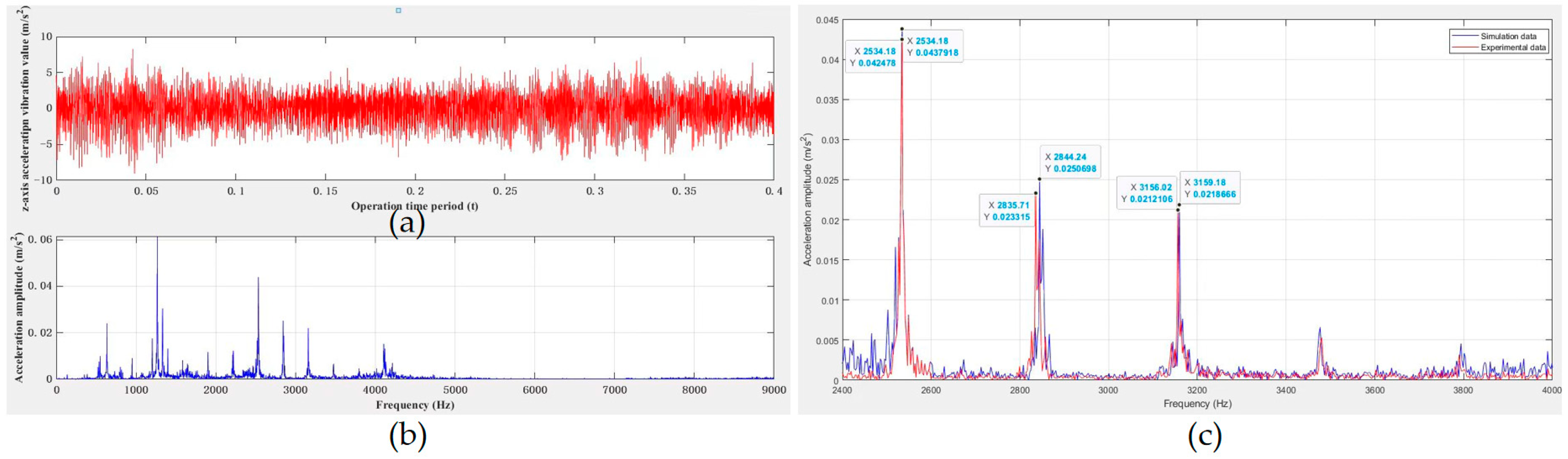
4.3. Analysis of Vibration Signal

The dynamic Equation (27) is numerically integrated using the fourth-order Runge–Kutta method with variable step length. During simulation, the outer ring is fixed and the inner ring rotates.
In Equation (27), by combining the torque with the vibration equation of the bearing, the equation can be obtained considering the wear factor, and the superposition process is shown in Figure 6.
Therefore, after superposition of Figure 6, the amplitude/frequency characteristics of bearings under nonlinear excitation in different loads are as shown in Figure 7 and Figure 8.
Through the wear calculation method, the frequency distribution value under the loads of 5000 N and 10,000 N is obtained. The wear frequency is always unchanged under different loads but, as the load increases, the amplitude of wear will also increase.

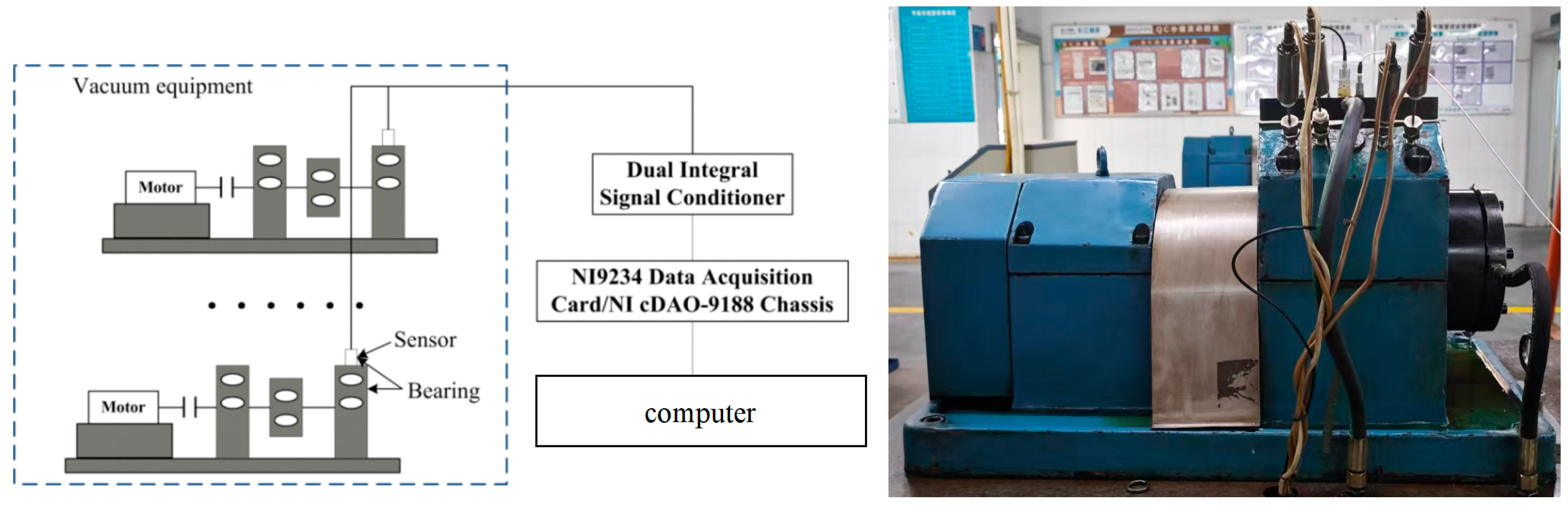
4.4. Vibration Signal Testing

Figure 9 shows the bearing vibration test bench. Two acceleration sensors are installed on the outer raceway of the bearing to detect the vibration acceleration signal. The parameters of the test stand are set: the inner ring speed is 6000 r/min, and the loads are 5000 N and 10,000 N. The sampling frequency is 10,240 Hz and the sample length is 102,400 points.
The vibration signal of the test in Figure 9 is Fourier-transformed and truncated with the Hamming window function to obtain the vibration signal under different loads.
From the analysis in Figure 10 and Figure 11, the frequency spectrum of radial vibration signals of angular contact ball bearings can be divided into natural frequencies ranging from 700 Hz to 1400 Hz, frequencies generated by friction excitation ranging from 500 Hz to 800 Hz, and frequencies generated by considering wear factors ranging from 2000 Hz to 2800 Hz. The above results indicate that under different loads, there will not be significant differences in the natural frequency, friction frequency, and wear frequency range, but the friction amplitude is the highest and the wear value is also significantly different. The results show clearly that the wear factor cannot be ignored when analyzing the vibration signal of the angular contact ball bearing. In this analysis, the wear frequency remains unchanged, but its amplitude is closely related to the load. As the load increases, the degree of wear also increases.
Furthermore, the amplitude/frequency characteristics of the angular contact bearing obtained from experimental test data are very close to those obtained from numerical calculations. Based on the marked coordinate values, the error range between the simulation results and experimental data were estimated to be 3.09–7.53%, indicating that the analytical model proposed in this study has good applicability. The model proposed in this study can predict the spectral characteristics of bearings at various stages during operation in advance. Through the online monitoring of bearing operating vibration signals and comparative analysis, it is possible to determine whether fault signals caused by wear have emerged in the bearing, providing a reliable method for life prediction of angular contact bearings caused by wear.

5. Conclusions

In this study, using the improved wear calculation method under dynamic load distribution, the dynamic load between the inner and outer rings and the raceway were calculated. Combined with the Archard wear model and mixed lubrication, the influence of load distribution on angular contact ball bearing wear was analyzed, and a bearing vibration equation considering wear factors was established. The method has theoretical significance for the wear spectrum, and provides a theoretical calculation model for the wear failure of bearings. According to the analysis of the calculation results, the wear frequency of the bearing is unchanged under different load distributions, but the amplitude increases accordingly with an increase in the load. The proposed model incorporates both dynamic load and mixed lubrication effects, enabling more accurate characterization of wear behavior during angular contact bearing operations. Consequently, it demonstrates superior predictive accuracy in online bearing life prognosis compared to conventional methods.
In the future, improvements will be mainly made in relation to the following three aspects:
The effects of multiple factors on wear in angular contact ball bearings will be further studied, such as the combined influence of temperature, lubrication, speed, and multi-directional loading. Kinematic analysis will be conducted under different operating conditions to identify the relationship between key parameters and wear.
More experimental data will be added, involving analysis under a wider range of operating conditions. The effective data will be compared with the wear model for validation.
This study primarily considers the effect of dynamic load distribution on wear based on the original wear model. The interactions between the balls and the cage, as well as between the cage and the raceway, also affect the kinematic and mechanical behavior of the bearing. Therefore, further theoretical analysis is needed to evaluate the impact of the cage on the bearing wear model.

Author Contributions

X.M. wrote the manuscript, and G.C., S.D., L.Y. and H.L. assisted with the results analysis. All authors have read and agreed to the published version of the manuscript.

Funding

This study was supported by the Science and Technology Research Program of Chongqing Municipal Education Commission (Grant Nos. KJQN202203207 and KJQN202303238).

Data Availability Statement

The original contributions presented in this study are included in the article. Further inquiries can be directed to the corresponding author.

Conflicts of Interest

The authors declare no conflicts of interest.

Appendix A

The unified Reynolds equation is
x ( ρ h 3 η p x ) + y ( ρ h 3 η p y ) = 2 x ( u r ρ h ) + 12 y ( v r ρ h ) + t ( ρ h )
where p is the pressure; h represents the film thickness; ρ is the density; η* represents the viscosity. In solving the 3D mixed-EHL model, the equation for the film thickness should include the 3D surface topography, elastic deformation, and contact geometry. Thus, the equation can be expressed as follows:
h ( x , y , t ) = h 0 + x 2 2 R x + y 2 2 R y + V ( x , y , t ) + S ( x , y , t )
where the normal approach h0(t), the original contact geometry x2/2Rx + y2/2Ry, and the 3D original roughness surface profiles S(x, y, t) can all be determined in advance. Since the elastic deformation V(x, y, t) is related to pressure, its calculation formula is as follows:
V ( x , y , t ) = 2 π E Ω p ( ξ , ζ ) ( x ξ ) 2 + ( y ζ ) 2 d ξ d ζ
In the analysis of mixed EHL, lubricants are usually considered non-Newtonian fluids; thus, the effective viscosity is expressed as follows:
1 η = 1 η τ 0 τ 1 Sinh ( τ 1 τ 0 )
where τ0 and τ1 denote the ambient and ultimate shear stresses, respectively, and η is the viscosity dependence on pressure and initial viscosity η 0 , which can be obtained as follows:
η = η 0 exp ( ln η 0 + 9.67 ) [ ( 1 + p / p 0 ) ] z 1 , z = α / 5.1 × 10 9 ( ln η 0 + 9.67 )
The lubricant density is also associated with pressure, in addition to the viscosity, and the density is given by
ρ = ρ 0 ( 1 + 0.6 × 10 9 p 1 + 1.7 × 10 9 p )
Pressure is generally used to determine the convergence for the numerical solution. The total pressure should be balanced with the external load; thus, we have
W ( t ) = Ω p ( x , y , t ) d x d y
Through the above formula, we can determine the film thickness and pressure distribution. On this basis, the proportion λ of the load carried by the asperity to the total load can be obtained.

Appendix B

M = m 0 0 0 m 0 0 0 I , q = [ x , y , θ y ] T , C = c s × Z 2 cos 2 α 0 Z 4 r sin ( 2 α ) 0 Z sin 2 α 0 Z 4 r sin ( 2 α ) 0 Z 2 r 2 sin 2 α K = k s × Z 2 cos 2 α 0 Z 4 r sin ( 2 α ) 0 Z sin 2 α 0 Z 4 r sin ( 2 α ) 0 Z 2 r 2 sin 2 α F = 3 2 K n δ 1 / 2 ω h t cos α j = 0 Z 1 cos ψ j ( cos ω c t sin ω c t ) 3 2 Z K n δ 1 / 2 ω h t sin α 3 4 d m K n δ 1 / 2 ω h t sin α j = 0 Z 1 cos ψ j ( cos ω c t sin ω c t )
In angular contact ball bearings, contact stiffness ks and contact damping cs under lubricated conditions are, respectively, expressed as
k s = ( 1 k c + 1 k f ) 1
c s = 6 π η 0 v s R 1.5 a 2 h c 1.5
where hc is the average film thickness at the center of the contact area; R is the equivalent radius of curvature of the contact; a is the major semi-axis of the contact ellipse.
The Hertz stiffness kc can be calculated as follows:
k c = d Q d δ Q 0 = 3 2 K n Q 0 1 / 2
Then, kf represents the oil film stiffness, which can be determined based on the film thickness and pressure distribution:
k f = i , j Δ p ( i , j ) Δ h c ( i , j )

References

  1. Liu, Q.; Guo, Y. Dynamic model of faulty rolling element bearing on double impact phenomenon. In Proceedings of the 2015 IEEE International Conference on Information and Automation, Lijiang, China, 8–10 August 2015; pp. 2017–2021. [Google Scholar]
  2. Lundberg, G.; Palmgren, A. Dynamic Capacity of Rolling Bearings. J. Appl. Mech. 1949, 16, 165–172. [Google Scholar] [CrossRef]
  3. Ioannides, E.; Harris, T.A. A New Fatigue Life Model for Rolling Bearings. J. Tribol. 1985, 107, 367–377. [Google Scholar] [CrossRef]
  4. Zaretsky, E.V. Fatigue criterion to system design, life, and reliability. J. Propuls. Power 1987, 3, 76–83. [Google Scholar] [CrossRef]
  5. Deolalikar, N.; Sadeghi, F. Fatigue Life Reduction in Mixed Lubricated Elliptical Contacts. Tribol. Lett. 2007, 27, 197–209. [Google Scholar] [CrossRef]
  6. Morales-Espejel, G.E.; Gabelli, A. A model for rolling bearing life with surface and subsurface survival: Surface thermal effects. Wear 2020, 461, 124–137. [Google Scholar] [CrossRef]
  7. Ghaffari, M.A.; Zhang, Y.; Xiao, S.H.P. Multiscale modeling and simulation of rolling contact fatigue. Int. J. Fatigue 2018, 108, 9–17. [Google Scholar] [CrossRef]
  8. Sesana, R.; Ossola, E.; Pagliassotto, S.; Rizzo, S.; Brusa, E. Influence of microinclusion in life of rolling elements: Experimental, microstructural, analytical and numerical investigation. Int. J. Fatigue 2020, 139, 345–353. [Google Scholar] [CrossRef]
  9. Shi, X.J.; Wang, L.Q.; Qin, F.Q. Relative fatigue life prediction of high-speed and heavy-load ball bearing based on surface texture. Tribol. Int. 2016, 101, 364–374. [Google Scholar] [CrossRef]
  10. Lin, F.H.; Wang, L.Q.; Li, Z.H.; Wu, J.Q.; Wei, S.S.; Su, K.; Liu, Y.B. Fatigue damage evolution and failure of G13Cr4Mo4Ni4V bearing steel under heavy load rolling contact. Tribology 2024, 44, 1–11. (In Chinese) [Google Scholar]
  11. Zhao, J.X.; Jiang, C.; Li, W.M.; Liu, H.M.; Li, X.M. Micro-pitting: Research progress and prospects. Tribology 2024, 44, 715–728. (In Chinese) [Google Scholar]
  12. Ardah, S.; Profito, F.J.; Dini, D. An integrated finite volume framework for thermal elasto-hydrodynamic lubrication. Tribol. Int. 2022, 177, 107935. [Google Scholar] [CrossRef]
  13. Chen, Q.; Yang, P.; Jiang, N.; Li, X.M.; Guo, F.; Yang, P.R. Experimental observation and numerical simulation of rheological properties of lubricating films under different sliding-rolling ratios. Tribol 2020, 40, 158–165. (In Chinese) [Google Scholar]
  14. Wu, J.; Wang, L.; He, T.; Gu, L.; Zhang, C.; Lu, Y. Investigation on the angular contact ball bearings under low speed and heavy load with coupled mixed lubrication and quasi-dynamic analysis. Lubr. Sci. 2020, 32, 108–120. [Google Scholar] [CrossRef]
  15. Wen, B.; Li, Y.; Wang, M.; Yang, Y. Measurement for Lubricant Distribution in an Angular Contact Ball Bearing and Its Influence Investigation. Lubricants 2023, 11, 63. [Google Scholar] [CrossRef]
  16. Wen, B.; Li, Y.; Li, Y.; Wang, M.; Zhai, J. Influence and Optimization of Nozzle Position on Lubricant Distribution in an Angular Contact Ball Bearing Cavity. Lubricants 2024, 12, 419. [Google Scholar] [CrossRef]
  17. Chen, G.; Wang, L.Q.; Gu, L.; Zhen, D. Heating analysis of the high speed ball bearing. J. Aerosp. Power 2007, 22, 165–168. [Google Scholar]
  18. Xie, Z.; Wang, Y.; Wu, R.; Yin, J.; Yu, D.; Liu, J.Q.; Cheng, T.H. A high-speed and long-life triboclectric sensor with charge supplement for monitoring the speed and skidding of rollingbearing. Nano Energy 2022, 92, 106747. [Google Scholar] [CrossRef]
  19. Park, D.; Kolivand, M.; Kahraman, A. An approximate method to predict surface wear of hypoid gears using surface interpolation. Mech. Mach. Theory 2014, 71, 64–78. [Google Scholar] [CrossRef]
  20. Lai, X.M.; Han, J.C.; Gao, P.; Qu, J.J.; Li, Y.; Tan, C.L.; Jiang, J. Research on wear mechanism of solid lubrication bearing in vacuum environment. Appl. Mech. Mater. 2015, 798, 424–429. [Google Scholar] [CrossRef]
  21. Jamari, J. Wear predication using GIWM (global incremental wear model) method. Rotasi 2012, 11, 1–4. [Google Scholar] [CrossRef]
  22. Cura, F.; Waqar, Q.; Andrea, M. A methodological approach for incremental fretting wear formulation. Tribol. Lett. 2016, 64, 1–10. [Google Scholar] [CrossRef]
  23. Cubillas, D.; Olave, M.; Llavori, I.; Ulacia, I.; Larranaga, J.; Zurutuza, A.; Lopez, A. Semi-analytical methodology to predict fretting damage areas in angular contact ball bearing raceways under variable loading. Wear 2022, 508–509, 204477. [Google Scholar] [CrossRef]
  24. Zhang, T.; Chen, X.; Gu, J.; Wang, Z. Influences of preload on the friction and wear properties of high-speed instrument angular contact ball bearings. Chin. J. Aeronaut. 2018, 31, 597–607. [Google Scholar] [CrossRef]
  25. Gu, J.; Zhang, Y.; Liu, H. Influences of wear on dynamic characteristics of angular contact ball bearings. Meccanica 2019, 54, 945–965. [Google Scholar] [CrossRef]
  26. Jang, J.Y.; Khonsari, M.M. On the wear of dynamically-loaded engine bearings with provision for misalignment and surface roughness. Tribol. Int. 2020, 141, 105919. [Google Scholar] [CrossRef]
  27. Wang, J.; Xu, H. Load sequence and life analysis of deep groove ball bearing. J. Mech. Eng. 2017, 53, 131–140. [Google Scholar] [CrossRef]
  28. Liu, Z.J.; He, S.Q.; Liu, H. Application of Rolling Bearing; China Machine Press: Beijing, China, 2007. [Google Scholar]
  29. Luo, J.W. Elastic Contact Problems of Rolling Bearing and Their Numerical Methods; Tsinghua University: Beijing, China, 1989. [Google Scholar]
  30. Ning, F.P.; Yao, J.T.; An, J.T.; Zhao, Y. Effect of assembly situation variation on wear of space precision bearings. J. Mech. Eng. 2017, 53, 68–74. [Google Scholar] [CrossRef]
  31. Wu, Z.G.; Lu, G.J. Analysis of angular-contact ball bearings under different conditions. Chin. J. Constr. Mach. 2013, 11, 107–111. [Google Scholar]
  32. Zhang, X.N.; Han, Q.K.; Chu, F.L. Contact angle of ball bearings based on a simplified Jones-Harris method. J. Vib. Shock 2013, 32, 170–175. [Google Scholar]
  33. Harris, T.A. Rolling Bearing Analysis; John Whey and Sons: Hoboken, NJ, USA, 1984. [Google Scholar]
  34. Luo, J.; Zhu, M.; Wang, Y.; Zheng, J.; Mo, J. Study on rotational fretting wear of bonded MoS2 solid lubricant coating prepared on medium carbon steel. Tribol. Int. 2011, 44, 1565–1570. [Google Scholar] [CrossRef]
  35. Li, Z. Wheel-Rail Rolling Contact and Its Application to Wear Simulation; TU Delft, Delft University of Technology: Delft, The Netherlands, 2002. [Google Scholar]
  36. Hu, Y.-Z.; Zhu, D. A Full Numerical Solution to the Mixed Lubrication in Point Contacts. J. Tribol. 1999, 122, 1–9. [Google Scholar] [CrossRef]
Figure 1. Schematic diagram of bearing coordinate system and rolling element azimuth angle.
Lubricants 13 00212 g001
Figure 2. Kinematics and contact equivalent model of angular contact bearing rollers.
Lubricants 13 00212 g002
Figure 3. Dynamic model of bearing.
Lubricants 13 00212 g003
Figure 4. Film thickness and pressure distribution of bearing contact zone during (a) early-stage, (b) mid-stage, (c) and final-stage periods.
Lubricants 13 00212 g004
Figure 5. Effect of wear time on wear depth.
Lubricants 13 00212 g005
Figure 6. Amplitude/frequency characteristics of the bearing under nonlinear excitation.
Lubricants 13 00212 g006
Figure 7. Spectrum of bearing under load 5000 N during steady wear stage.
Lubricants 13 00212 g007
Figure 8. Spectrum of bearing under load 10,000 N during steady wear stage.
Lubricants 13 00212 g008
Figure 9. Angular contact ball bearing vibration test bench.
Lubricants 13 00212 g009
Figure 10. Time-domain and frequency-domain characteristics of bearings under 5000 N load: (a) time-domain; (b) frequency-domain; (c) comparison of simulation data and experimental data.
Lubricants 13 00212 g010
Figure 11. Time-domain and frequency-domain characteristics of bearings under 10,000 N load: (a) time-domain; (b) frequency-domain; (c) comparison of simulation data and experimental data.
Lubricants 13 00212 g011
Table 1. Detailed information about the used bearing.
Number of BallsBall Diameter
mm
Pitch Diameter
mm
Groove Curvature Radius
mm
Initial Contact Angle
Degree
Outer Raceway Diameter
mm
Inner Raceway Diameter
mm
1622.225125.260111.628140147.7264102.7938
Disclaimer/Publisher’s Note: The statements, opinions and data contained in all publications are solely those of the individual author(s) and contributor(s) and not of MDPI and/or the editor(s). MDPI and/or the editor(s) disclaim responsibility for any injury to people or property resulting from any ideas, methods, instructions or products referred to in the content.

