Article

Tribological Performance of an Automatic Transmission Fluid Additized with a Phosphonium-Based Ionic Liquid Under Electrified Conditions

by
Alejandro García Tuero
1,*,
Seungjoo Lee
2,
Antolin Hernández Battez
1 and
Ali Erdemir
2
1
Department of Construction and Manufacturing Engineering, University of Oviedo, Pedro Puig Adam, s/n, 33203 Gijón, Spain
2
Mechanical Engineering Department, Texas A&M University, College Station, TX 77843, USA
*
Author to whom correspondence should be addressed.
Lubricants 2025, 13(5), 209; https://doi.org/10.3390/lubricants13050209
Submission received: 14 April 2025 / Revised: 2 May 2025 / Accepted: 6 May 2025 / Published: 9 May 2025
(This article belongs to the Special Issue Tribology of Electric Vehicles)

Abstract

:
This study explores the impact of a phosphonium-based IL (trihexyltetradecylphosphonium bis(2-ethylhexyl) phosphate, [P6,6,6,14][BEHP])) on the tribological performance of an automatic transmission fluid (ATF) when used as an additive. Tests were carried out under both non-electrified and electrified conditions in a reciprocating ball-on-flat tribometer. After tribological tests, the worn surfaces were subjected to extensive structural and surface analyses to understand the underlying friction and wear mechanisms. The addition of this ionic liquid improved the anti-wear protection of the ATF, although the wear rates were consistently higher than in non-electrified conditions. The tribofilm formed by the IL-containing ATF augmented the electrical resistance at the contact interface, thereby reducing the likelihood of electrification-induced wear. Our results point to the need for further improvements in the chemical formulation of the ionic liquids, like the one used in the present study, to enhance the protection of sliding surfaces against wear in future electric vehicle applications.

Graphical Abstract

1. Introduction

The European Environmental Agency (EEA) [1] and the U.S. Environmental Protection Agency (EPA) [2] have identified the transportation sector as a significant contributor to greenhouse gas (GHG) emissions. As documented in their respective reports, this sector was responsible for 23% and 29% of total GHG emissions in 2022 within their respective geographic regions. Consequently, the implementation of new measures, particularly in the area of road transport, is of critical importance for the realization of several global objectives, as outlined in the 2030 Agenda for Sustainable Development [3]. These objectives include the Affordable and Clean Energy goal (SDG 7), the Industry, Innovation, and Infrastructure goal (SDG 9), the Sustainable Cities and Communities goal (SDG 11), the Responsible Consumption and Production goal (SDG 12), and the Climate Action goal (SDG 13).
It is evident that the electrification of vehicles represents one of the most effective strategies for achieving these targets. The emergence of electric vehicles (EVs) in recent years offers a powerful and decisive opportunity to fight against climate change, primarily due to their significantly higher energy efficiency and little or no greenhouse gas (GHG) emissions compared to internal combustion engine (ICE) vehicles [4,5]. Moreover, besides full electric vehicles, hybrid electric vehicles (HEVs) are instrumental in enabling the transition towards a zero-emissions scenario by 2035, as outlined in the Conference of the Parties (COP26) [6] and subsequent meetings [7].
If we look back at the ever-expanding portfolio of EVs, we can perhaps classify them into four categories: mild hybrid, full hybrid, plug-in hybrid, and fully electric vehicles. This classification is determined by the battery’s size and charging method, as well as the size of the electric motor (EM) [8]. Hybrid electric vehicles (HEVs) exhibit various configurations, and in those instances, the EM is integrated within the transmission housing, where it interacts with the automatic transmission fluid (ATF). As a result, the ATF must fulfill several critical requirements, including magnetic compatibility, corrosion resistance, the prevention of ventilation and foaming at elevated speeds, thermal compatibility, material compatibility, and electrical compatibility [9,10].
In all of these vehicles, the tribology in electrified contacts has been a growing area of research in recent years, driven by the growth of the electric vehicle market. Nevertheless, since the middle of the twentieth century, studies have been conducted on how electric currents contribute to the deterioration of metallic contacts and lubricants [11,12], as well as how the thickness of the lubricant film affects the impedance and voltage at the interface, which in turn affects the formation of surface defects [13,14]. Furthermore, the load and temperature in the contact are also relevant factors in defining the electric discharge machining currents [15]. More recently, research efforts have concentrated on the tribological characterization of different lubricants under relevant test conditions of EV drivetrains. Due to their superior chemical stability and thermal and electrical properties, polyalphaolefins (PAOs) represent a class of base oils that is most desired in electric vehicle (EV) applications. Accordingly, these oils have been subjected to extensive tribological testing under electrified conditions [16,17]. The results of these studies show that the coefficient of friction (COF) and wear of rubbing surfaces increase by approximately 20% and 10%, respectively, upon passing currents of above 1.5 A through the contact interface.
Similar trends have also been observed in other oils, such as automatic transmission fluids (ATF) [17,18,19], with comparable outcomes. For example, Ali et al. [17] reported a 10% mean friction increase when current is increased from 2 to 10 A in a ball-on-disc reciprocating test machine. In another study, Aguilar-Rosas et al. [18] reported a +35% increase in COF and a +10% increase in wear in a four-ball test machine. In both cases, the maximum Hertzian pressures exceeded 1.5 GPa, and in the case of Aguilar-Rosas, the test temperature was 75 °C, as specified in the four-ball test standard (ASTM D4172) [20]. In contrast, Farfán et al. [19] employed a ball-on-flat test configuration at a constant speed using a constant flux of lubricant and significantly reduced maximum Hertzian pressure (<0.6 GPa). The results demonstrated a decrease in friction under 1.5 A conditions in comparison to the non-electrified tests, although wear was dramatically higher (+300%).
In contrast, the studies examining fully formulated gear oils and base mineral oils [18,19,21,22] have yielded friction reductions with diverse test configurations, four-ball, pin-on-disc, and ball-on-flat (all of them with constant sliding speed), starting with 1.5 A current intensity. Notably, the authors in [18] have obtained different outcomes for gear oils than those already researched for the base oils in the same conditions. In their research with a four-ball configuration, they observed an increase in friction for the gear oil (+100%) and a decrease for the mineral base oil (−40%). The authors hypothesized that the underlying cause of the friction and wear decrease in the base oil tests was the absence of antioxidant additives. They suggest that the action of electrification on the polar additives of the formulated oils is perhaps responsible for these different behaviors.
Similarly, the tribological performance of various additives has been evaluated under electrified conditions. Zinc dialkyldithiophosphate (ZDDP) is a well-known antioxidant and antiwear additive. It was one of the first lubricant additives to be tested in electrified conditions [23]. The authors observed a reduction in wear and friction when a ZDDP-additivated ester base fluid was employed. The authors postulated that the ZDDP functions to create a protective layer that reduces the electric current passing through the contact. The results obtained by different authors with other additives (including some solid additives), such as h-BNO@PDA (a modified hexagonal boron nitride nanolubricant) or graphene nanoparticles, also showed stark differences. In the case of graphene nanoparticles, Aguilar-Rosas et al. [16] discovered that they enhance the thermal and rheological characteristics of PAO4 in the absence of electrical stimulation, while friction and wear increased by 10 and 20%, depending on the concentration under electrified conditions. In contrast, Ali et al. [17] proved that the h-BNO@PDA additive enhances the tribological performance of the PAO6 base oil under electrified conditions, and even that of a reference ATF-6S, which exhibited superior wear resistance under non-electrified conditions. These observations indicate that the electrical properties of the fluid are a critical factor influencing its tribological performance.
In this context, one class of additives that has been reported to be rather effective in modifying electrical conductivity is ionic liquids (ILs) [24]. This is mainly because ionic liquids possess a number of advantageous properties that could be very important for the development of high-performance lubricants for EV drivetrains. They are electrically conducting, polar substances and their non-flammable and non-volatile nature combined with high thermo-oxidative stability could also be highly desirable attributes for EV applications [25,26,27,28]. Due to their high polarity and surface reactivity, ILs can adsorb both physically and chemically on metal surfaces, thereby promoting the formation of tribolayers that can, in turn, reduce friction and/or wear [29,30,31]. However, ILs are not miscible in non-polar hydrocarbon oils from groups I, II, and III, due to their highly polar natures. Consequently, they are commonly used at very low concentrations [32,33,34,35], while they are more compatible with polar oils [36,37,38]. Nevertheless, a family of ILs with enhanced miscible properties in nonpolar hydrocarbon oils (mineral oils and PAOs) has lately been identified and used to enhance the anti-friction and -wear properties of carrier oils [39]. These ILs are based on a symmetrical cation of phosphonium. In recent years, there has been a notable increase in studies examining the use of these ILs as lubricant additives, largely due to their aforementioned enhanced miscibility [40,41,42,43,44,45,46].
In general, the incorporation of ILs as additives has resulted in marked reductions in friction and/or wear under non-electrified sliding conditions. A review of the literature reveals a scarcity of publications reporting lubricated tribological tests involving ionic liquids under electrified conditions. Dold et al. [47] and Yang et al. [48,49] can be credited for conducting some of the earliest electrified tribological tests in the presence of an imidazolium ionic liquid (1-ethyl-3-methylimidazolium bis(trifluoromethylsulfonyl)imide [C2C1IM][Tf2N]UP), in carrier oils. It is important to note, however, that the electrification of the ball-on-disc configuration employed in their study did not entail the electrification of the two samples. This was because the electrodes were situated within both the disc and the fluid, not the ball. As the ball was conveniently isolated from the equipment, this resulted in the avoidance of current passing through the sliding contact interface. With this configuration, they obtained a 35% reduction in COF under electrified conditions with a sliding speed ranging from 0 to 1.5 m/s. They attributed this improvement to the adsorption of ions (facilitating the formation of tribolayers) and electrokinetic effects supporting the hydrodynamic lubrication regime. Yang et al. [48] used three imidazolium ILs as additives to a propylene carbonate lubricant and obtained a 10% COF improvement in electrified conditions in one case (1-octyl-3-methylimidazolium tetrafluoroborate [OMIm][BF4]) in a ball-on-disc configuration at constant speed. The authors also tested this IL on a nitrided AISI 4340 disc, keeping the rest of the test conditions the same [49]. They found no variation in COF in this case. All these tests on ILs were carried out in a configuration in which the fluid was electrified, but the current could not pass through the ball sample as it was electrically isolated, so the results cannot be strictly compared to those of this research. To the best of our knowledge, there are no other documented cases of electrified tribological tests conducted on phosphonium-based ionic liquids. Nevertheless, studies investigating the electrical compatibility of ATFs in which ionic liquids were utilized as additives have been conducted and documented in the literature [50,51].
In this study, we conducted a large number of parametric tribological tests in order to assess and unravel the effect of incorporating a phosphonium-based ionic liquid (IL) as an additive in an ATF on its friction and wear performance when a steady electric current passes through the ball and disk contact interface. In addition to the tribological tests, the wear scars and tracks formed on the surface of the specimens were examined using advanced surface and structure analytical techniques to ascertain how the ionic liquid affected the wear performance and underlying mechanisms of sliding contact interfaces.

2. Materials and Methods

2.1. Materials

The reference oil utilized for this procedure was an ATF, the properties of which are listed in Table 1. This ATF was formulated with 89 wt.% of a base fluid constituted by two mineral oils (YUBASE 3 and YUBASE 6) belonging to the API Group III, and 11 wt.% of the HiTEC 3460 additive package (a high performance additive package from Afton Chemicals Ltd., Bracknell Berkshire, UK).
This ATF constitutes a commercial solution. The selection was made on the basis that it was identified as the most suitable option among other ATFs in previous studies [51,52,53]. A number of these studies concentrated on the compatibility of ATFs with polymeric materials (elastomers and structural materials) found in electric vehicle transmissions [52,53]. The selection was also influenced by a preceding study that focused on tribological performance and electrical compatibility [51].
The trihexyltetradecylphosphonium bis(2-ethylhexyl) phosphate ([P6,6,6,14][BEHP]) IL was provided by IOLITEC GmbH (Heibronn, Germany) (Table 2) and was added to the ATF as an additional additive in a concentration of 1 wt.% over the already fully formulated oil, thus increasing the total additive concentration to 12.11 wt.%. The mixture of the ATF and the IL was prepared using a magnetic stirrer Seattle Alki Scientific MI0102003 (Fristadenlab, Reno, NV, USA) for a period of 60 min at a speed of 1000 rpm. This ATF + IL mixture was selected on the basis of empirical investigation into tribological performance and electrical compatibility, as detailed in [50].
The electrical conductivity of both ATF and ATF + IL fluids were measured in a previous work [50]. Table 3 shows the electrical conductivity values for the two fluids used in this study.
The kinematic (ν) and dynamic viscosity (μ) of both ATF and ATF + IL were also measured in [50] at different temperatures, and they are shown in Table 4.

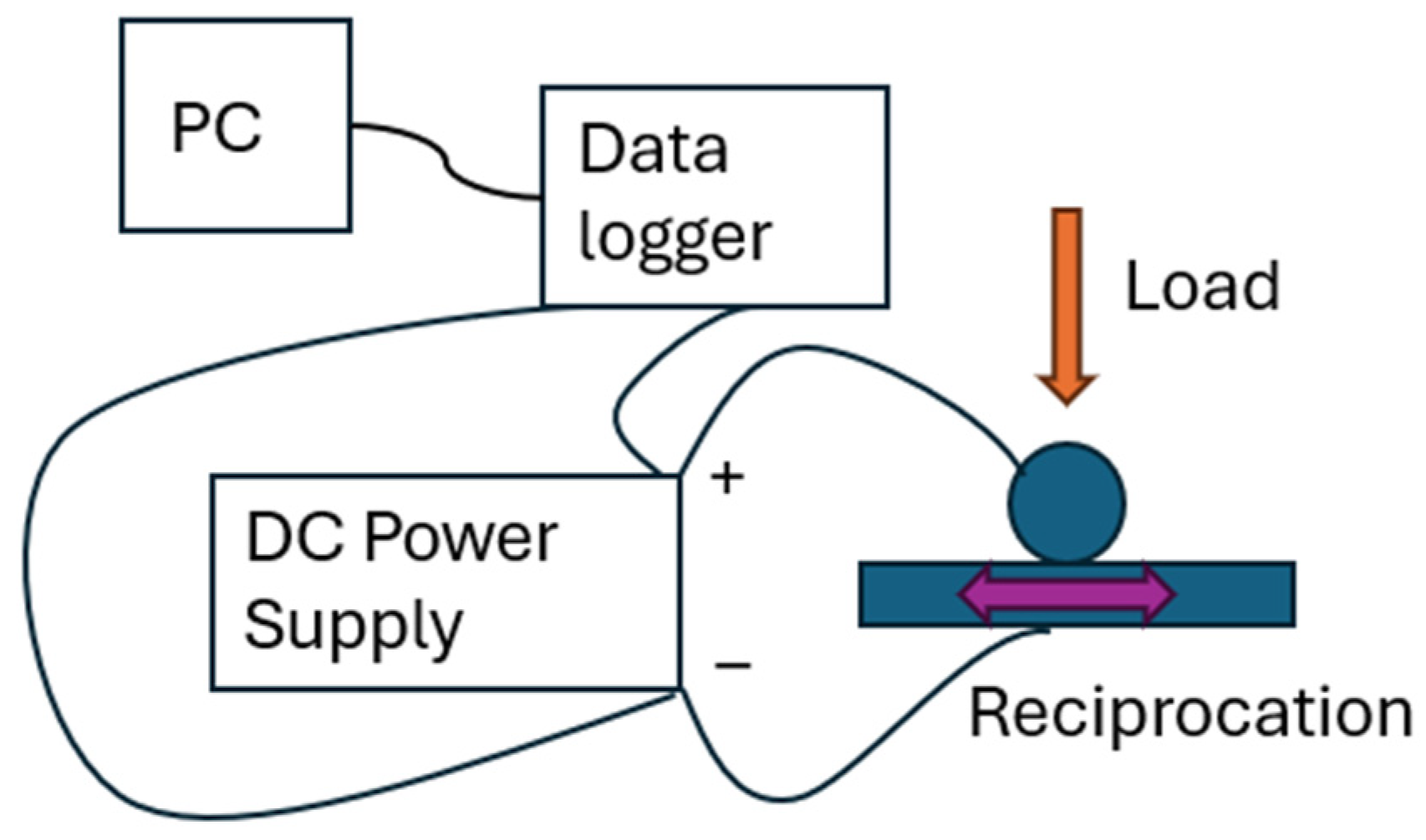
2.2. Tribological Tests

To investigate the frictional behavior of the ATF with and without IL, as well as under electrified and non-electrified conditions, 30-min-long reciprocating tests were conducted in a ball-on-flat tribotest configuration. The device utilized for these experiments was a modified Bruker Tribolab (Bruker Corp. Billerica, MA, USA). The experiments were conducted using 50 and 80 N loads with 10 mm diameter steel balls, which yielded maximum Hertzian contact pressures of 1.67 GPa and 1.95 GPa, respectively. The stroke length was maintained at 1 mm with a frequency of 15 Hz. Both the ball and flat samples were made of AISI 52100 steel, with a nominal hardness value of 64 HRC, and a roughness of 0.02 μm. The tests were conducted at room temperature and humidity (i.e., 35–40% RH).
The modification of the test equipment entailed the substitution of the ball and flat holders (which were originally in direct contact with other parts of the equipment, hence grounded) with those machined from PEEK. This ensured the insulation of the equipment. The components of the ball holder that were solely in contact with the ball were left unaltered to permit the current to flow through the contact. Given the absence of established methodologies and instrumentation for conducting tribological testing in an electrical setting, we have devised our own approach and methodology. A direct current (DC) power supply Keithley, model 2230-30-1 (Keithly Instruments, Solon, OH, USA) was employed to provide a predefined DC current to the contact surface throughout the duration of the test. The device was connected to the conductive component of the ball holder and the flat sample via direct wires. A Hantek 365F data logger (Qingdao Hantek Electronic Co. Ltd., Qingdao, Shangdong, China) and the associated software, Hantek 365 v.1.0.0.4, were employed to maintain control of the electrical signal. The electric connections are schematized in Figure 1. The experiments were conducted at room temperature under three different direct current (DC) amplitudes: 0 A, 0.5 A, and 1 A.

2.3. Surface Analysis

Wear volume measurements were conducted using a Bruker Contour GTK profilometer with ×2.5, ×5, and ×20 augmentation lenses. The ×5 lens was utilized for the tests, as it provided the optimal image resolution for capturing the complete wear scar in a single image. The profilometer was operated through the Vision 64 v.5.8.4 software. In order to identify the wear mechanisms and the surface–lubricant chemical interaction that occurred during the tribological tests, scanning electron microscopy, energy-dispersive spectroscopy (SEM/EDS), and Raman analysis were conducted on the flat specimen after the tribological tests. The SEM/EDS analyses were performed in a JEOL JSM-IT200 instrument (JEOL Ltd., Akishima, Japan) operated at 15 kV. The confocal Raman microscope was a Renishaw model inVia (Renishaw plc, Wotton-under-Edge, UK), equipped with Leica optics (100× magnification) (Leica, Wetzlar, Germany). The measurements were conducted using a Renishaw RL532-08 laser with a wavelength of 532 nm and a power of 2.5 mW. A minimum of six points were scanned for each scar under analysis. The number of accumulations for each spectrum was 10, with an integration time of 10 s.

3. Results and Discussion

3.1. Friction and Wear

Figure 2 shows the coefficient of friction (a) and wear volume (b) for each test conditions employed during the tests. The vertical bars represent the mean values obtained from three repetitions, and the error bars indicate the typical deviation.
The evolution of friction at a load of 50 N exhibits a similar pattern for both lubricants, with and without IL. In general, the values are slightly higher when the lubricant contains IL, which has been previously reported in non-electrified conditions [50]. This phenomenon is more pronounced at a 50 N load, whereas at higher loads, the friction is similar with or without the IL. However, this is not the case at higher current intensity (1 A), which also generates higher friction with the IL-containing lubricant. The results obtained with the ATF are consistent with those using this type of lubricant with higher current discharge conditions [17,18], but when the load is reduced, electrification is reported to improve friction [19]. Among other lubricants that have already been tested in electrified conditions, PAOs show similar results to those of ATFs and this study during a 1 A test [16,17], with a higher COF increase (up to 20%), most likely due to the higher-intensity current employed. On the other hand, those authors that tested base mineral oils and fully formulated gear oils under electrified conditions [18,19,21,22] reported reductions in friction. Notably, the authors of [18] obtained different outcomes for gear and base oils. The authors hypothesized that the underlying cause of the decrease in friction in the base oil test was the absence of antioxidant additives. They suggest that the action of electrification on the polar additives of the formulated oils is responsible for these different behaviors, which would also explain the results obtained in all of the 1 A tests in this study. The 0.5 A conditions seem to generate different behaviors, i.e., being more dependent on load (Figure 2).
The results of the ATF 50 N at 0.5 A test show a different behavior that cannot be contrasted, since none of the tests in the literature, as far as we know, have used these electric current test conditions. It is well known that much of the performance of lubricants depends on the temperature reached in the contact spots, so the lower intensity could compensate for the higher pressure, resulting in similar results for these test conditions to those of Farfan et al. [19], who used a higher intensity (1.5 A) and a lower maximum pressure (<0.6 GPa).
Regarding wear, as has also been reported previously [50], the lubricant with IL is more effective in non-electrified conditions. This is more evident at lower loads (i.e., 50 N), while when the load increases to 80 N, the difference in wear decreases, as has been also observed with friction. Thus, we can say that the role of the load is significant, as is the role of the current intensity, in situations where the contact is electrified. The use of the IL as an additive for the ATF results in a notable enhancement in performance under 50 N and 0.5 A test conditions, as evidenced by a considerable reduction in wear volume compared to that of the ATF. It seems plausible that the ionic liquid facilitates the dissipation of the electric current due to an increase in electrical conductivity (Table 3). Upon increasing the load to 80 N, both lubricants exhibited comparable behavior, albeit with heightened variability observed in the ATF + IL lubricant. Indeed, the ATF demonstrates a marginal enhancement in performance at elevated loads, exhibiting comparable outcomes to those observed at 50 N. Conversely, the ATF + IL system exhibits a notable increase in wear, reaching values that exceed those observed with the ATF alone.
The use of the ATF + IL fluid at a higher current (1 A) yields much higher friction values, especially under an 80 N load, as shown in Figure 2a. As for the wear, at a lower load of 50 N, the wear is nearly identical for ATFs with and without IL, though marginally superior in the case of the IL one (negligible in light of the variability of results). However, in the 80 N tests, while the ATF results are similar to those at 50 N, the performance of the ATF + IL shows a 16% lower wear volume.
The results of the wear tests are consistent with the findings of most of the studies referenced in the COF discussion above. However, some authors have reported minimal increases or even wear reductions [16,18,22,54]. Aguilar et al. [16] obtained small wear reductions of up to 10% by adding graphite nanoparticles to the PAO 4 base oil, which alone slightly increased the wear results under electrified conditions. This behavior of the additized base oil was attributed to the lower breakdown voltage of the lubricant with respect to the PAO 4 and to the reorientation of the nanoparticles to form a chain-like nanostructure. Both the breakdown voltage drop in an IL additized ATF [50] and the realignment of the IL to form smoother tribofilms under electrified conditions [48,49] have also been reported. This could explain the better wear test results of the ATF + IL fluid against the ATF alone. The other studies [18,22,54] that present low variations of wear under electrified conditions also used base oils with or without additives. For fully formulated lubricants, like ATFs and gear oils, the results are consistent with the results in [17,18,19,22,54].
Figure 3 illustrates the mean potential (in mV) recorded during the electrified tests, with the associated standard deviation represented by error bars. This is significant because it provides clear evidence of the resistance presented by the fluid and tribofilm to the passage of electric current. As the intensity of the electric current is maintained at a constant level throughout the course of the experiment, any observed differences in the mean potential indicate variations in the nature of the contact between the samples, which in turn affects the current passing through the system and the extent of Joules heating being generated at the interface.
Despite the established higher electrical conductivity of the ATF + IL fluid in comparison to the ATF alone (Table 3), the mean electrical potential observed is consistently higher for the ATF + IL fluid across all conditions, with the exception of the 50 N and 1 A conditions where the values are nearly identical. This discrepancy is most likely due to the differences in the dielectric properties of the tribolayers formed by the two lubricants, with the ATF + IL exhibiting a more substantial resistance against the flow of electricity. This appears to be more prevalent in the case of 80 N and 1 A conditions, demonstrating the highest mean electrical potential (and thus, the highest resistance to the passage of electric current). Somewhat lower wear among all the 1 A tests shown in Figure 2b could be attributed to the slightly superior wear protective nature of such an insulating tribolayer formed at 1 A.
Figure 4 shows the 3D images obtained by the profilometer after the wear test measurements. It can be observed that the ATF + IL lubricant performs well in non-electrified conditions. The most interesting finding in the electrified test images is the variation of the wear zones as a function of current intensity, load, and fluid, indicated in the image by yellow ovals. While the wear is concentrated at the end of the wear scar for the 50 N and 0.5 A tests for both fluids, when the load is 80 N, the most worn zones change to those shown in Figure 4. On the contrary, in the 1 A tests, the wear is concentrated in two longitudinal bands at the edges of the wear scar at lower loads and in only one of these longitudinal bands at higher loads.
These findings may be explained by the lubrication regime at each location within the wear scar. Given that the reciprocating test is conducted at a variable speed and constant load, and that the mean COFs are between 0.075 and 0.12 (Figure 2a), it is possible that the lubrication regime varies depending on the specific zone of the scar in which the ball is located at any given moment. The sliding speed plays a pivotal role in determining the film thickness, being both at their maximum value at the center of the track. Consequently, the central region of the track exhibits minimal wear, irrespective of the testing conditions. Inversely, the speed at the corners is zero. Therefore, it can be assumed that the wear should be maximal at this point of the wear scar. The fact that both lubricants maintain the distribution of wear throughout the entire track in non-electrified conditions, coupled with the notable increase in wear evident in all electrified tests, suggests that the wear is primarily caused by the current passing through the contact. Consequently, the changing wear zones must be determined by where electrical discharges occur.
In the 50 N tests, at an intensity of 0.5 A, the wear observed at the end of the tracks indicates that the lubricant film can prevent the electric current from passing through the contact while the sliding speed is sufficient to minimize the direct metallic contact. This protective effect is supported by the dissipative character of the ATF + IL lubricant [50]. However, when the speed reaches zero, the fluid film reaches its minimum thickness, resulting in an increase in metallic contact, so current discharge happens and subsequently wear increases. With an identical current value but an 80 N load, the lubricant film is disrupted at a higher speed, resulting in wear occurring prior to the ball coming to a complete stop. In these conditions, we can see good protection of the corners, similarly to what happens in the tests at 50 N and 0 A. When the current is increased to 1 A, there is a greater tendency for it to flow through the lubricant film. Consequently, the current is able to traverse the contact point where the lubricant film is thinner, situated in proximity to the edges of the wear track. Furthermore, in accordance with Coulomb’s law, it can be postulated that the charges at the flat sample will also be concentrated at the edges of the track, thereby facilitating the passage of current. This would account for the observed concentration of wear along the edges in the aforementioned tests, particularly in the ATF + IL test, given the higher electrical conductivity of the lubricant (Table 3).

3.2. Surface Analysis

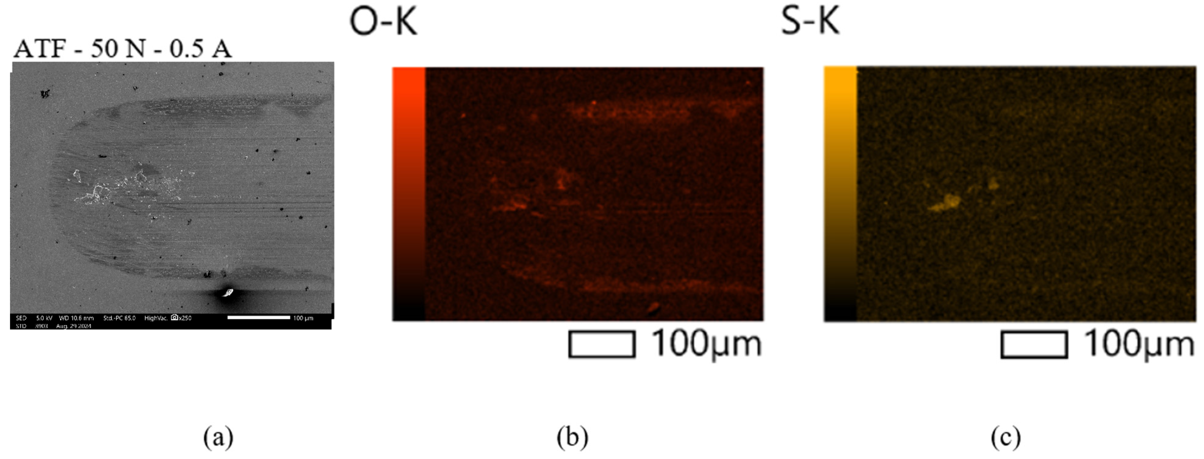
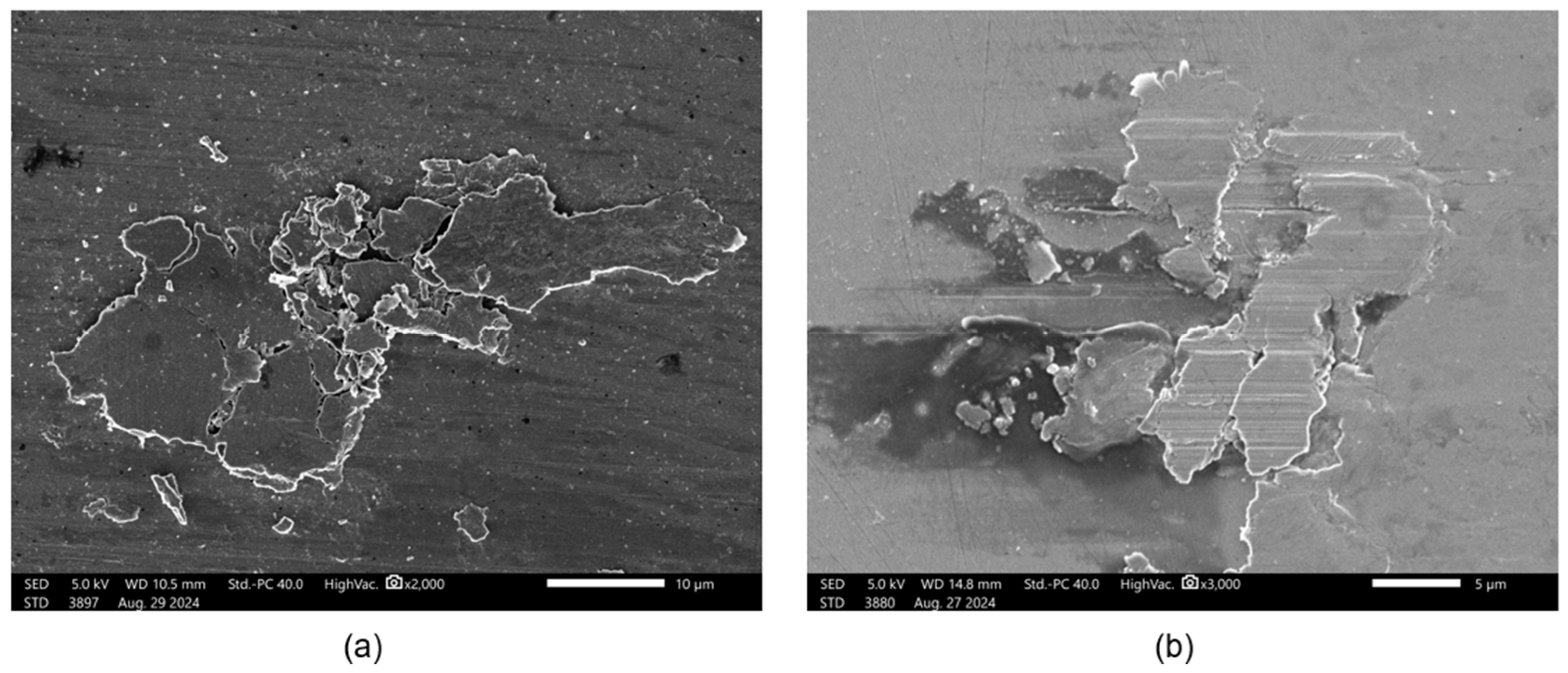
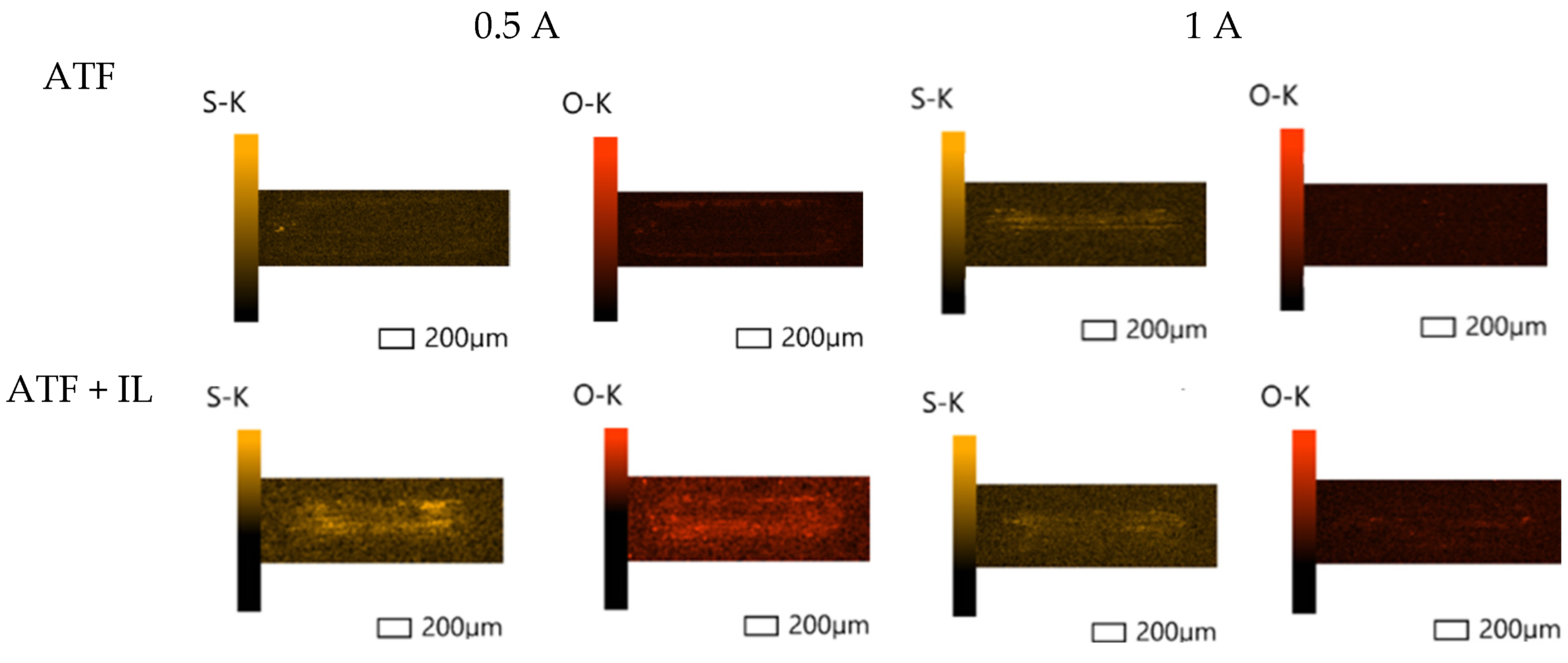
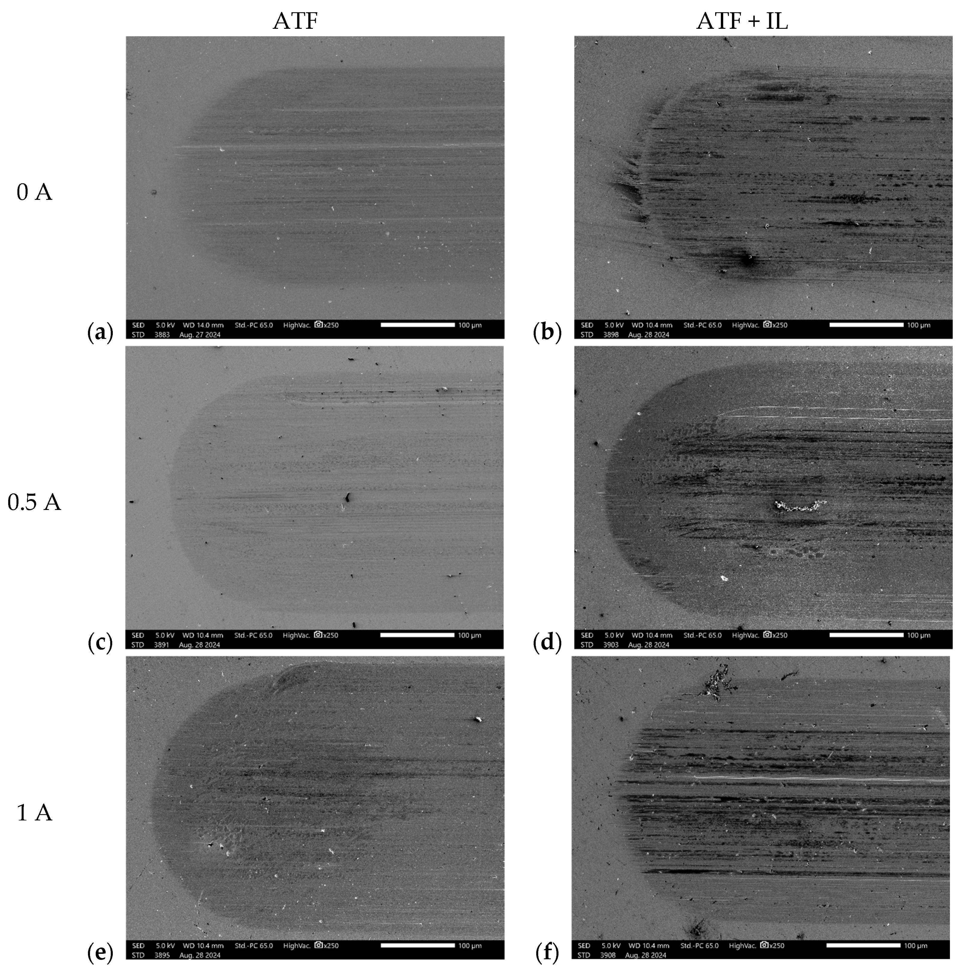
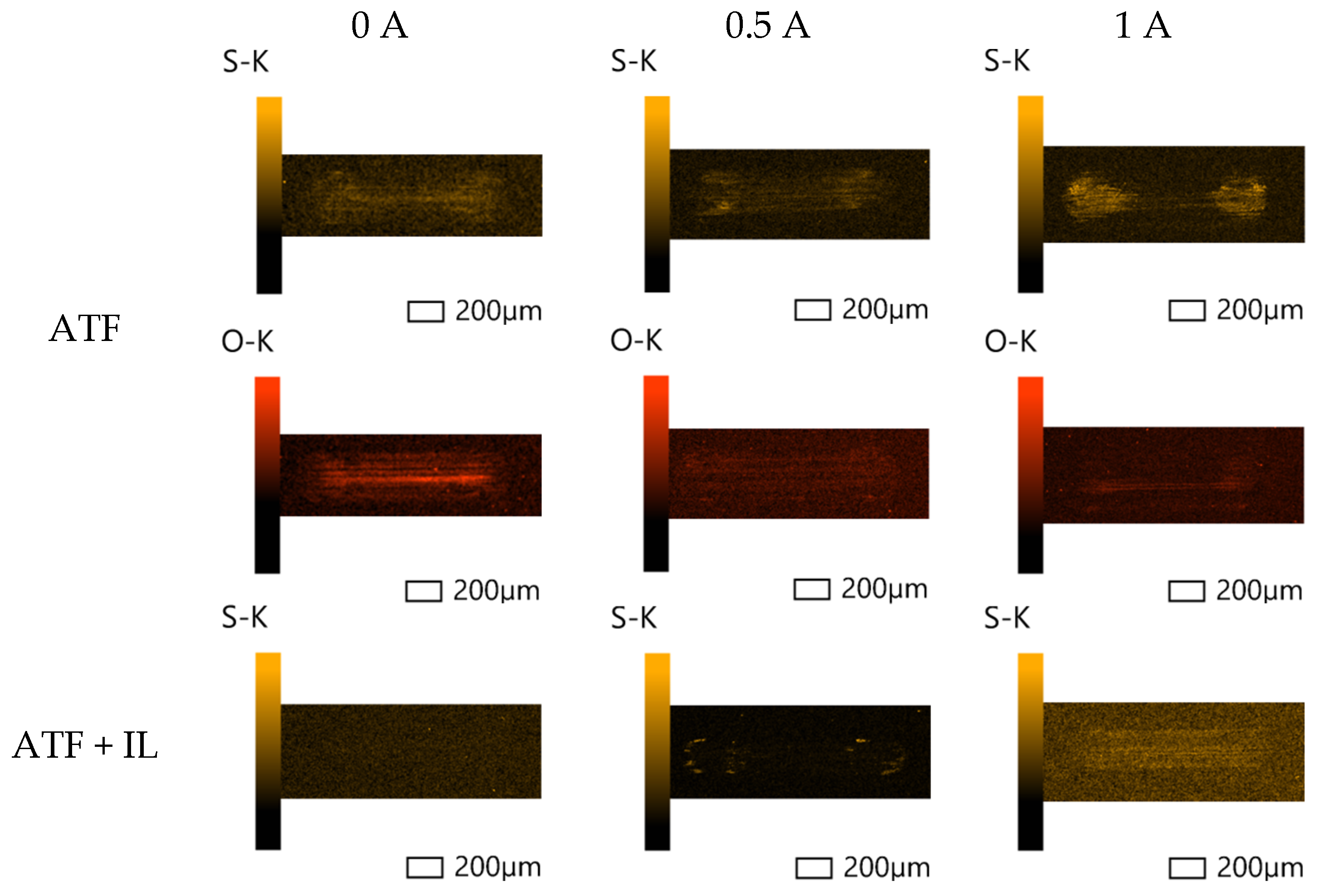
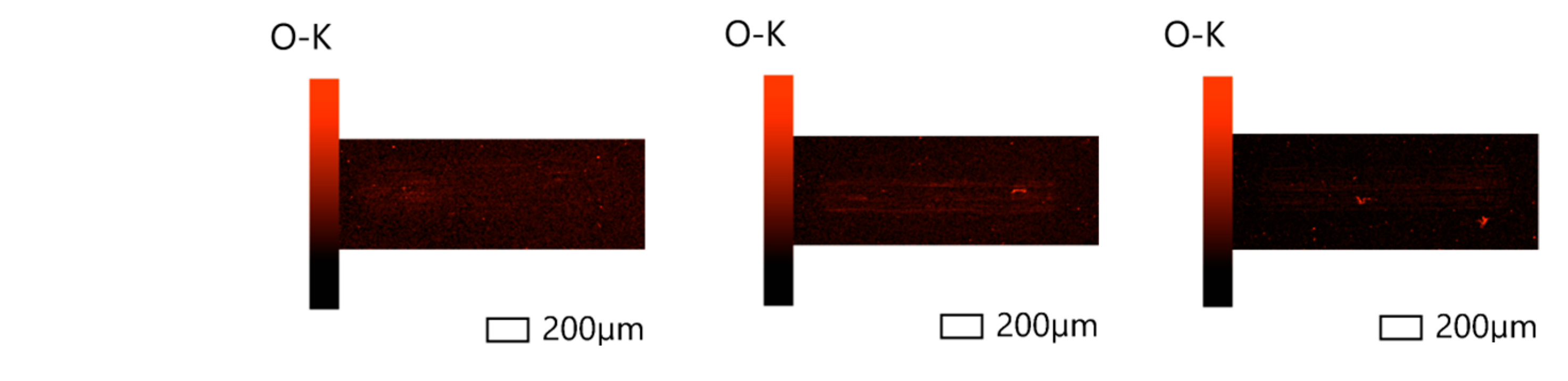
3.2.1. Scanning Electron Microscopy (SEM) and Energy-Dispersive Spectroscopy (EDS)
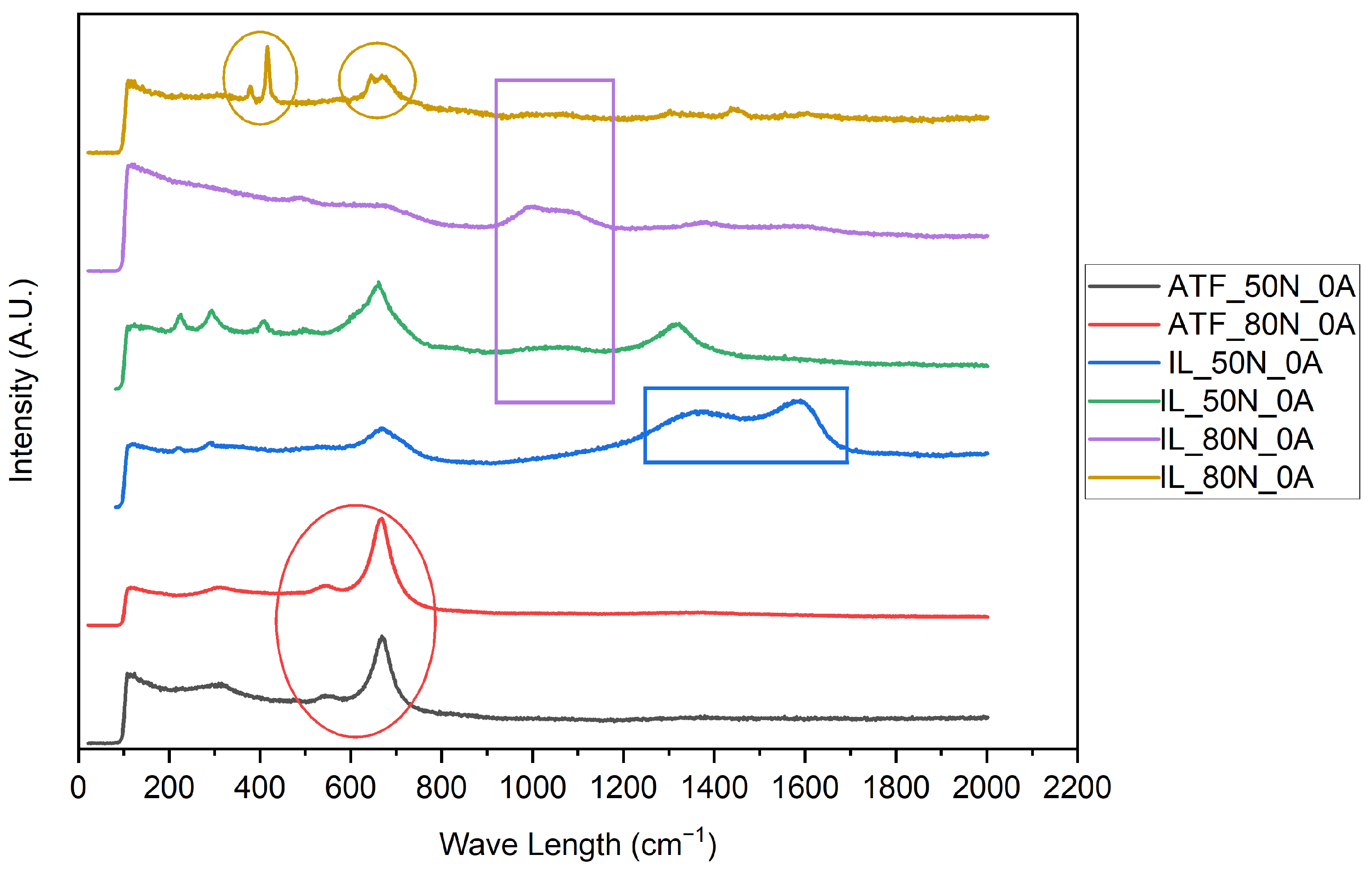
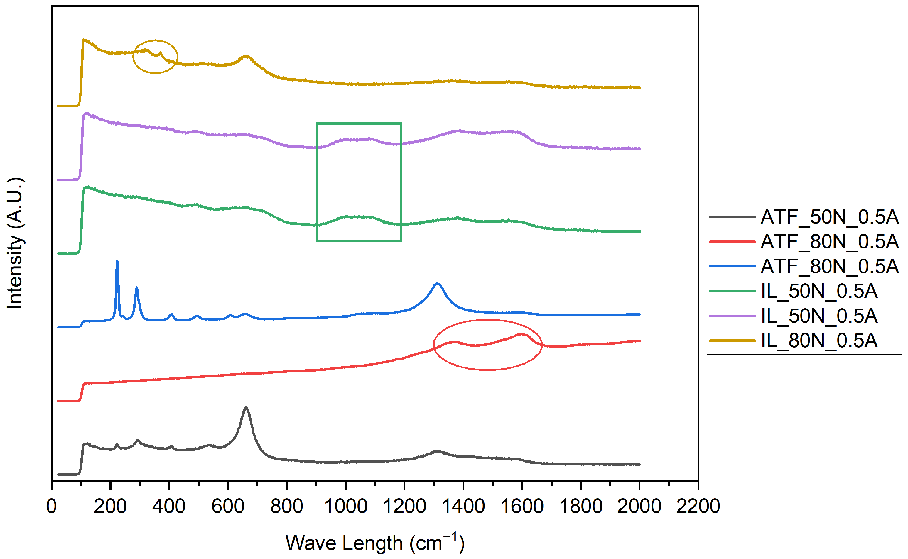
A surface analysis of the flat probes was conducted to try to identify the wear mechanisms during the different tests, and to check the possible interactions between the metallic surface and the lubricant. Figure 5 shows the SEM images of the worn surface following the friction and wear tests with the ATF and ATF + IL, at a load of 50 N.
It can be observed that the primary wear mechanism in the non-electrified tests with the ATF was mild/adhesive (wear) or polishing wear in nature. However, upon passing current through the contact, a transition to abrasive wear (as manifested by deep scratches and loose third-body wear particles) started to emerge with this fluid (see arrow in Figure 5c), as has already been reported by the authors of [16,18,19,55], with the presence of abrasive wear marks or scratches being even more pronounced when the current is higher (Figure 5e). This might be caused by the known ATF wear behavior under electrified conditions that the oxidation products separate from the surface and thus stop being a part of the tribolayer and contributing to the third body abrasive wear process [17,18]. At 0.5 A, the presence of large-scale shaped particles at the end of the abrasive grooves indicates that the mechanism in the remainder of the scar may be either adhesive or due to subsurface fatigue.
Figure 6 illustrates the EDS maps of O and S in the region of the wear scar where the abrasive particles accumulate during the test with the ATF at 50 N and 0.5 A. These particles’ primary composition included oxygen and sulfur. We can also observe oxidized areas on the edges of the wear scar where some of the wear particles were pushed aside.
The images of the wear tracks produced in the tests with the ATF + IL fluid (Figure 5b,d,f) exhibit notable differences compared to those of the ATF alone. The images demonstrate the presence of additional blackened areas at 0 and 0.5 A, indicating the formation of distinct tribofilms compared to those observed under identical load and electrification conditions with the ATF. Abrasive grooves or wear marks cannot be discerned on the wear track formed in ATF + IL. Upon increasing the current to 1 A, the images (Figure 5e,f) exhibit a markedly different aspect. Specifically, it displays a multitude of grooves in the sliding direction in the case of the ATF, though no discernible, noteworthy particles are visible. This suggests that the tribofilm was formed at some point, albeit with a distinct composition, as the particles were generated when the ATF tribofilm was worn out or broken through when the abrasion had started. This result is highly comparable to those obtained by other authors in similar conditions [17,18,19,54,55]. On the contrary, the aspect of the wear scar after the tests with ATF + IL at 1 A is more similar to that of the ATF with 0.5 A, even showing large abrasive grooves with scale-shaped particles at the end of the scar. Thus, it looks like the presence of the IL in the lubricant protects the surface from abrasive wear more effectively under lower current conditions.
Figure 7 provides a detailed illustration of the subject matter depicted in a red rectangle in Figure 5c,f. It can be observed that the particles have been detached from the surface and deposited at the end of the stroke during the reciprocating tests in both cases.
As can be observed in these augmented images, the shape of the particles is similar, although larger in the case of the ATF at 0.5 A test (Figure 7a), considering that the augmentation is not the same in both pictures. It is also noteworthy that the surface of the particles exhibit a distinctive aspect, with the particles in the ATF + IL sample displaying indications of abrasive wear. This may indicate that the tribofilm formed with the ATF + IL fluid was more resilient and only broken through near the end of the 1 A test, thereby largely protecting the metallic surface from abrasion. This may account for the superior performance of the ATF + IL in the 50 N and 0.5 A test with regard to wear, given that the tribofilm was able to last longer during the test. In contrast, in the 50 N and 1 A test, both tribofilms were broken at some point of the test, resulting in a very comparable degree of wear.
Figure 8 depicts the EDS maps of the 50 N tests for the ATF. The EDS maps show that the distribution of the elements is in accordance with the hypothesis of a compositional shift of the tribofilm between the ATF 0.5 and 1 A tests. This is exemplified by the prevalence of oxygen over sulfur with a 0.5 A current, with sulfur only discernible at the particle level, and of sulfur over oxygen with a 1 A current, with sulfur manifesting throughout the center of the scar, while oxygen is only observable in minute oxide particles. Furthermore, the image demonstrates a more pronounced formation of a tribofilm following the ATF + IL 0.5 A test. Although EDS mapping only provides information on distribution and does not offer a quantitative analysis in relation to other tests, it is evident that both sulfur and oxygen are present throughout the majority of the surface area in the ATF + IL lubricated sample. Conversely, in the 1 A tests, oxygen is observed to be attached to the abrasive grooves, while sulfur is found to accumulate primarily in the corners of the scar, where sliding speed is slower and lubrication occurs under boundary conditions.
In quantitative wear terms, it can be stated that the tribofilm observed in Figure 8 for the ATF + IL at 0.5 A contributes to wear protection, as evidenced by the results in Figure 1, as well as increasing electrical resistance (Figure 3). Similarly, the nearly identical sulfur and oxygen distribution observed on the wear scar for the 1 A tests result in a very similar wear in these conditions for both fluids, as the electrical resistance was almost the same.
Figure 9 depicts the SEM images of the 80 N tests at 0, 0.5, and 1 A, for the ATF and ATF + IL fluids. The distinction between the two fluids is more apparent in this instance, where the load is higher than that in Figure 5. In the case of ATF + IL non-electrified test, the distribution of the black zones is dispersed, whereas in the electrified tests, they exhibit a linear pattern in the sliding direction. With 0.5 A, the concentrations of sulfur and oxygen are concentrated in the center of the scar, without reaching the corners. In the case of ATF + IL, we can see big concentrations of white spots, typically from oxidized particles, coinciding with the higher worn zones (indicated in Figure 4) for these tests. In contrast, in the 1 A test, the black lines extend to the border of the track and form a wider longitudinal and centered band. This layer can also be observed in Figure 4, although wear only occurred on one edge of the track.
Figure 10 illustrates the energy-dispersive spectroscopy (EDS) mapping for oxygen (O) and sulfur (S) in the 80 N tests. The oxidation areas are positioned in the sliding direction in the ATF non-electrified and 1 A tests, although in the latter, it is not as clear. In contrast, they spread throughout the track in the 0.5 A test. The ATF + IL maps demonstrate notable differences. In the non-electrified test, there are no discernible tracks of oxygen, whereas in the electrified tests, it is primarily concentrated in larger particles. Nevertheless, some tracks can be discerned in the 0.5 A test, albeit with less clarity than in the non-electrified ATF case.
The distributions of sulfur and oxygen are markedly disparate. In the ATF tests, sulfur is primarily concentrated in the corners of the track, with this distribution being more pronounced at higher electrical intensities. In the ATF + IL tests, sulfur deposition appears to be inhibited in the non-electrified test, while it accumulates in the edges of the corners in the 0.5 A test, predominantly in small spots, and spreads throughout the central zone (and away from the edges) in the 1 A test.

3.2.2. Raman

Figure 11 illustrates the most distinctive Raman spectra for the 0 A tests within the wear tracks. The results enable the identification of different compounds. The presence of magnetite (Fe3O4) is evident in all the resulting surfaces, although it is only reproduced for the ATF tests in this plot. This is represented by the 670 and 540 cm−1 Fe-O stretch vibration peaks (red oval) [56,57]. The two peaks at 1340 and 1580 cm−1, which correspond to the amorphous graphite D and G bands [58,59], are highlighted in the blue rectangle and are also present, albeit with lower intensity, in the lilac line. The green line illustrates a highly representative spectrum of Fe3P [56], exhibiting characteristic Fe2O3 peaks at 220, 290, 410, and 1318 cm−1 [56,57,60]. The peaks at 930 and 1100 cm−1 (lilac rectangle) are indicative of phosphate compounds, predominantly iron [61,62] and zinc polyphosphates [56,62]. Additionally, the golden line illustrates two notable regions corresponding to phosphate (PO4) compounds [63]. Solid state compounds with P=S bonds are represented by doublets in the 550–730 cm−1 and 655–865 cm−1 bands [64], in coincidence with the golden oval on the right side.
These findings confirm the presence of strong oxidation in the case of ATF and more complex tribofilms, with P and S compounds, in the case of ATF + IL that would explain the great wear protection shown during the non-electrified tests.
Figure 12 illustrates the most distinctive Raman spectra for the 0.5 A tests within the wear tracks. The most relevant novelty is that we can find hematite in the samples tested with the ATF lubricant, which we did not find in the non-electrified tests, in two different forms, Fe2O3 and α-Fe2O3 [65], which correspond to the black and blue lines, respectively. Furthermore, graphite can also be identified in the 80 N, red line, sample. The most notable distinction in the ATF + IL spectra is that in instances where phosphates and graphite co-occur (green and lilac), the graphite displays greater intensity, in contrast to observations made in the un-electrified tests. Iron and zinc phosphates’ bands are highlighted within the green rectangle. Additionally, the PO4 and P=S bands persist in the gold line, albeit exhibiting diminished intensity. These findings suggest a predominance of iron oxides over an adsorbed tribofilm, reason why abrasive wear appeared, especially in the ATF tests.
Figure 13 illustrates the Raman spectra for the flat samples used in the 1 A tests. The most characteristic finding of these tests is the absolute prevalence of graphite almost everywhere in the wear tracks. In the ATF + IL, it is still possible to find some phosphate traces (green and gold lines) but with much less intensity. In the case of the gold line, it is notable that the PO4 band around 400 cm−1 is still present, but the one at 600–700 cm−1, also involving the P=S bonds, disappears. On the contrary, the 900–1100 cm−1 band for iron and zinc polyphosphates is reinforced.
As demonstrated in Figure 11, Figure 12 and Figure 13,electrification has been shown to enhance the formation of carbon compounds with a highly disordered structure. Although carbon is usually present in steel–steel lubricated contacts, simultaneous mechanical sliding and electrical current apparently promote the decomposition of lubricant and/or hydrocarbon-based additives under the high pressure and shear forces of the sliding contacts [66]. Additionally, the intensified electron transfer facilitates the structural rearrangement of some of the carbons into disordered graphite by modifying the interfacial bonding [66,67]. The formation of disordered graphite under high loads has the tendency to increase the COF [68], which is consistent with our results (Figure 2).
Overall, the results presented above confirm the very complex nature of the tribochemical events under electrification. The addition of a phosphonium-based ionic liquid (i.e., trihexyltetradecylphosphonium bis(2-ethylhexyl) phosphate, [P6,6,6,14][BEHP]) further complicate the mechanisms involved in the formation of tribolayers, which have a very distinct physical and chemical nature that ultimately govern friction and wear. In general, the discharge of electricity through the contact interfaces has an adverse impact on friction and wear, consistent with the large body of previously reported ATF and gear oils. Our results also point to the need for the development of novel ILs specifically tailored for future ATF to be used for electrified contacts where they can result in the formation of tribofilms which are far more effective in reducing friction and wear [43,50,69,70,71] since the off-the-shelf ILs used so far may fall short under electrification.

4. Conclusions

The tribological behavior of lubricating fluids is a critical factor for enhancing the performance and prolonging the lifetime of any vehicle. However, our results show that such fluids may not live up to expectations under the electrified contact conditions of EV drivetrains as our systematic studies have confirmed that significant increases in friction and wear can occur with such fluids (even further fortification with an ionic liquid well-known for its anti-friction and wear properties). Overall, based on the experimental and surface and structure analytical findings of our study, we provide the following conclusions:
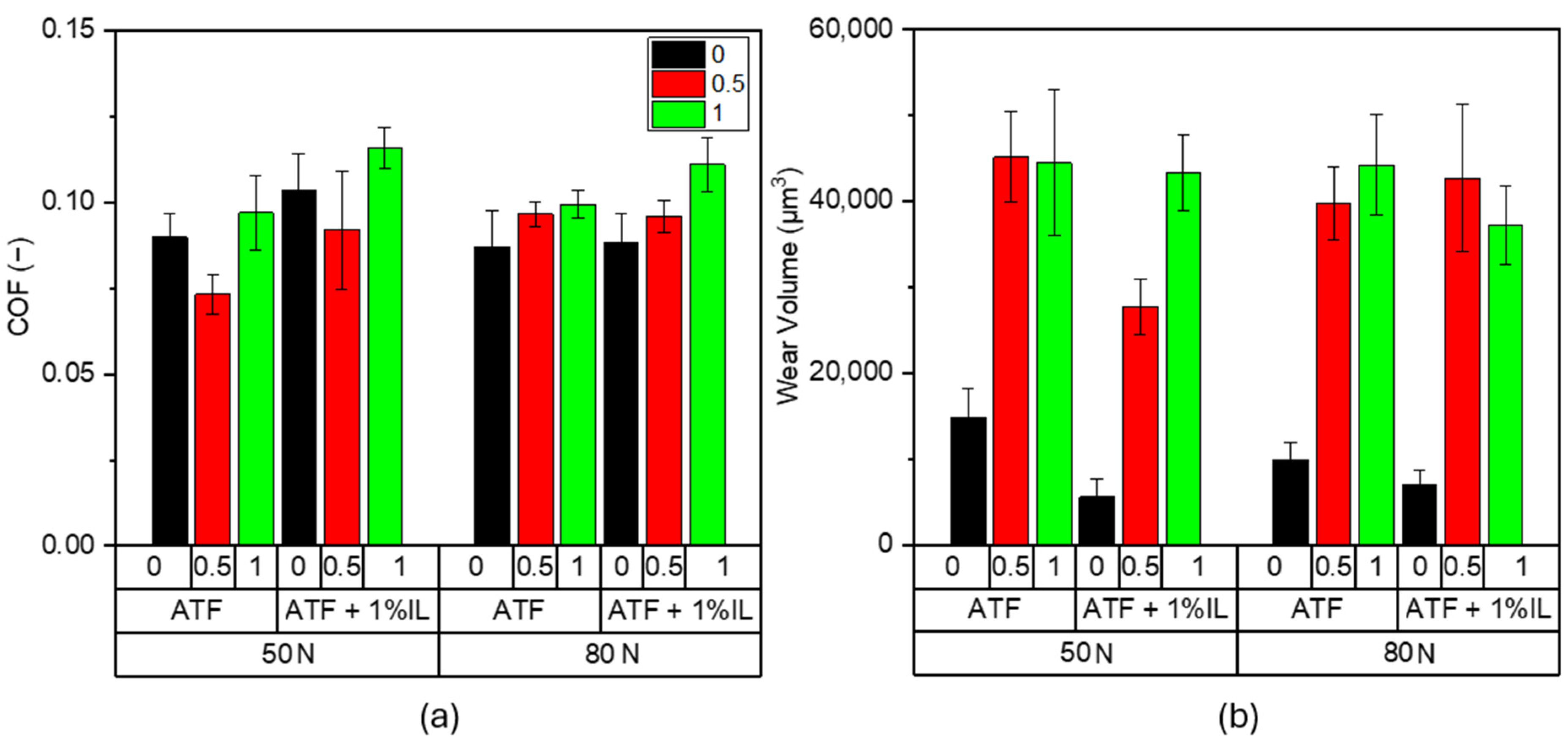
  • In general, regardless of the use of the ionic liquid (i.e., trihexyltetradecylphosphonium bis(2-ethylhexyl) phosphate ([P6,6,6,14][BEHP])) as an additive in the ATF, friction coefficients of steel test pairs show a tendency to increase under electrification. The magnitude of increases is somewhat higher under 80 N (creating a Peak Hertz pressure of 1.95 GPa).
  • The wear rates of test pairs also increase under electrification, especially in the presence of an IL in ATF, suggesting that existing additives in ATF (even with the additional fortification with an IL) do not necessarily provide the level of anti-wear properties needed. This is consistent with the findings reported on other fully formulated conventional oils. The slight decrease in wear in the case of test pairs lubricated by the ATF + 1 wt.% IL is ascribed to the somewhat more enhanced protective capacity of the specific tribofilms formed.
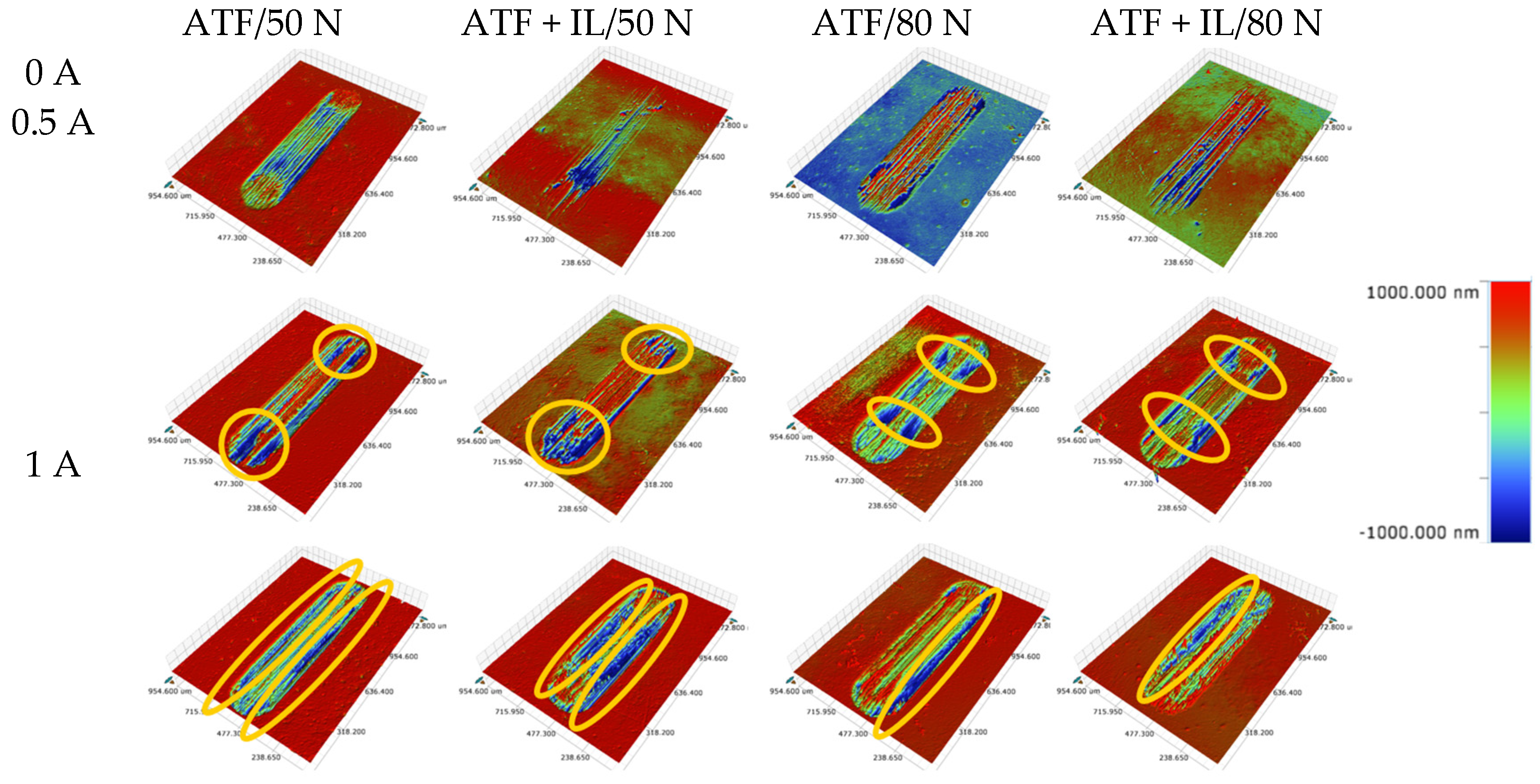
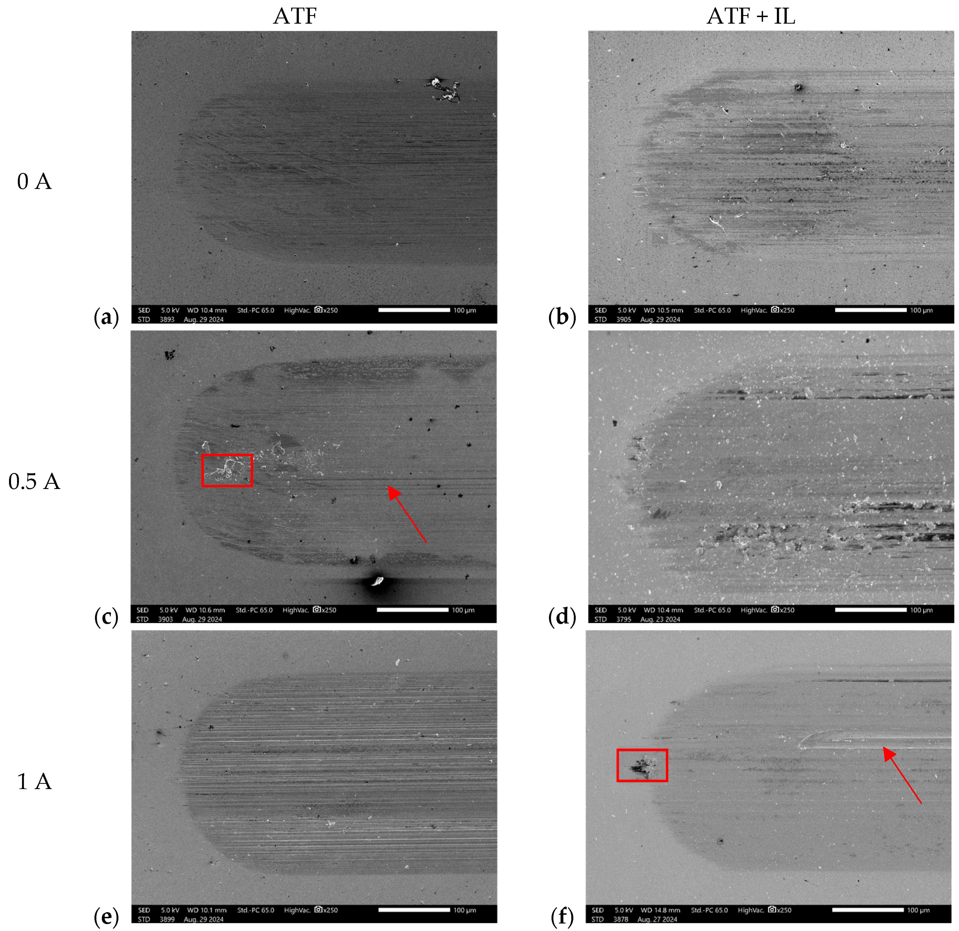
  • Based on the microscopic analyses, the use of trihexyltetradecylphosphonium bis(2-ethylhexyl) phosphate ([P6,6,6,14][BEHP]), as an additive to an ATF, suppressed the onset of the abrasive wear mechanism (as the sliding wear tracks were very smooth and lacked deep abrasive wear grooves). Based on the Raman analysis, the formation of a tribofilm that is rich in sulfates and phosphates may have avoided the abrasive wear process in the case of IL-containing fluid.
  • Finally, our results point to the need for further improvements in the chemical formulation of the kind of ionic liquid used in our study and others; specifically, their physical (i.e., rheology, electrical, thermal conductivity) and chemical (surface reactivity, stability under electrification, etc.) properties need to be further tailored for electrified contacts. The IL (i.e., [P6,6,6,14][BEHP]) used in our study showed marked improvements in friction and wear under non-electrified sliding conditions (especially under milder loading) but failed under severe loading and higher current conditions. Accordingly, in the future, the knowledge gained from our study and other studies should be used for the development of the next generation of ILs with a capacity to better regulate the electrical conductivity and/or dielectric properties of the lubricants, coupled with superior ability to enhance the protection of the sliding surfaces against the electrically induced wear, thus making them potentially very valuable in future EV applications.

Author Contributions

Conceptualization, A.G.T., A.H.B. and A.E.; methodology, A.G.T., S.L. and A.E.; validation, A.G.T. and A.E.; formal analysis, A.E.; investigation, A.G.T. and S.L.; resources, A.G.T. and A.E.; data curation, A.G.T.; writing—original draft preparation, A.G.T.; writing—review and editing, S.L., A.H.B. and A.E.; visualization, A.G.T.; supervision, A.H.B. and A.E.; project administration, A.G.T., A.H.B. and A.E.; funding acquisition, A.G.T. and A.E. All authors have read and agreed to the published version of the manuscript.

Funding

This research was funded by the Ministry of Science, Innovation and Universities (Spain) under the Jose Castillejo program, by awarding Alejandro García Tuero with the scholarship of reference CAS22/00371 to develop this research, and the Texas A & M Engineering Experiment Station startup funds and the Governor’s University Research Initiative for financial support.

Data Availability Statement

Data will be made available on request.

Acknowledgments

The authors would like to acknowledge the technical support of Ezequiel Vázquez, from the RIAIDT facilities (University of Santiago de Compostela, Spain) in the configuration of the Raman tests. Authors also acknowledge the Texas A & M Engineering Experiment Station startup funds and the Governor’s University Research Initiative for financial support.

Conflicts of Interest

The authors declare no conflicts of interest. The funders had no role in the design of the study; in the collection, analyses, or interpretation of data; in the writing of the manuscript; or in the decision to publish the results.

References

  1. EEA. Trends and Projections in Europe 2022; EEA Report No 10/2022; European Environment Agency: Copenhagen, Denmark, 2022. [Google Scholar]
  2. Sources of Greenhouse Gas Emissions|US EPA. Available online: https://www.epa.gov/ghgemissions/sources-greenhouse-gas-emissions#transportation (accessed on 19 September 2024).
  3. Miranda, J.J.; Scholz, I.; Agard, J.; Bobylev, S.N.; Dube, O.P.; Hathie, I.; Kanie, N.; Madise, N.J.; Malekpour, S.; Montoya, J.C.; et al. Global Susutainable Developement Report 2023. Times of Crisis, Times of Change; United Nations: New York, NY, USA, 2023. [Google Scholar]
  4. Holmberg, K.; Erdemir, A. The Impact of Tribology on Energy Use and CO2 Emission Globally and in Combustion Engine and Electric Cars. Tribol. Int. 2019, 135, 389–396. [Google Scholar] [CrossRef]
  5. Woydt, M. The Importance of Tribology for Reducing CO2 Emissions and for Sustainability. Wear 2021, 474–475, 203768. [Google Scholar] [CrossRef]
  6. COP26 Transport Declaration. Available online: https://cop26transportdeclaration.org/en/?contextKey=en#fulldeclaration (accessed on 15 June 2022).
  7. Kooshian, C.; Posada, F.; Yang, Z.; Blumberg, K.; Weber, F.; Füssler, J.; Winkelman, S. Compendium on Greenhouse Gas Baselines and Monitoring. Passenger and Freight Transport; United Nations: New York, NY, USA, 2023. [Google Scholar]
  8. Lubes’n’Greases. Perspective on Electric Vehicles. 2019 Annual Report; Lubes’n’Greases: West Falls Church, VA, USA, 2019. [Google Scholar]
  9. Gangopadhyay, A.; Hanumalagutti, P.D. Challenges and Opportunities with Lubricants for HEV/EV Vehicles. In Proceedings of the STLE Annual Meeting, Nashville, TN, USA, 19–23 May 2019. [Google Scholar]
  10. Farfan-Cabrera, L.I. Tribology of Electric Vehicles: A Review of Critical Components, Current State and Future Improvement Trends. Tribol. Int. 2019, 138, 473–486. [Google Scholar] [CrossRef]
  11. Kaufman, H.N.; Boyd, J. The Conduction of Current in Bearings. ASLE Trans. 1959, 2, 67–77. [Google Scholar] [CrossRef]
  12. Prashad, H. Investigation of Damaged Rolling-Element Bearings and Deterioration of Lubricants under the Influence of Electric Fields. Wear 1994, 176, 151–161. [Google Scholar] [CrossRef]
  13. Chiou, Y.-C.; Lee, R.-T.; Lin, C.-M. Formation Criterion and Mechanism of Electrical Pitting on the Lubricated Surface under AC Electric Field. Wear 1999, 236, 62–72. [Google Scholar] [CrossRef]
  14. Beyer, M.; Brown, G.; Gahagan, M.; Higuchi, T.; Hunt, G.; Huston, M.; Jayne, D.; McFadden, C.; Newcomb, T.; Patterson, S.; et al. Lubricant Concepts for Electrified Vehicle Transmissions and Axles. Tribol. Online 2019, 14, 428–437. [Google Scholar] [CrossRef]
  15. Magdum, O.; Gemeinder, Y.; Binder, A. Investigation of Influence of Bearing Load and Bearing Temperature on EDM Bearing Currents. In Proceedings of the 2010 IEEE Energy Conversion Congress and Exposition, Atlanta, GA, USA, 12–16 September 2010; pp. 2733–2738. [Google Scholar]
  16. Aguilar-Rosas, O.A.; Alvis-Sánchez, J.A.; Tormos, B.; Marín-Santibáñez, B.M.; Pérez-González, J.; Farfan-Cabrera, L.I. Enhancement of Low-Viscosity Synthetic Oil Using Graphene Nanoparticles as Additives for Enduring Electrified Tribological Environments. Tribol. Int. 2023, 188, 108848. [Google Scholar] [CrossRef]
  17. Ali, M.K.A.; Zhang, C.; Yu, Q.; Sun, Y.; Zhou, F.; Liu, W. Exploring Tribo-Electro-Chemistry Mechanisms of h-BNO@PDA as Lubricant Additives under Electrified Conditions for Electrical Vehicles Powertrain. Tribol. Int. 2024, 200, 110092. [Google Scholar] [CrossRef]
  18. Aguilar-Rosas, O.A.; Farfan-Cabrera, L.I.; Erdemir, A.; Cao-Romero-Gallegos, J.A. Electrified Four-Ball Testing—A Potential Alternative for Assessing Lubricants (E-Fluids) for Electric Vehicles. Wear 2023, 522, 204676. [Google Scholar] [CrossRef]
  19. Farfan-Cabrera, L.I.; Erdemir, A.; Cao-Romero-Gallegos, J.A.; Alam, I.; Lee, S. Electrification Effects on Dry and Lubricated Sliding Wear of Bearing Steel Interfaces. Wear 2023, 516–517, 204592. [Google Scholar] [CrossRef]
  20. ASTM D4172; Standard Test Method for Wear Preventive Characteristics of Lubricating Fluid (Four-Ball Method). ASTM International: West Conshohocken, PA, USA, 2016.
  21. Cao-Romero-Gallegos, J.A.; Taghizadeh, S.; Aguilar-Rosas, O.A.; Dwyer-Joyce, R.S.; Farfan-Cabrera, L.I. The Effect of Electrical Current on Lubricant Film Thickness in Boundary and Mixed Lubrication Contacts Measured with Ultrasound. Friction 2024, 12, 1882–1896. [Google Scholar] [CrossRef]
  22. Cao-Romero-Gallegos, J.A.; Farfan-Cabrera, L.I.; Erdemir, A.; Pascual-Francisco, J.B. Lubricated Sliding Wear of Gear Material under Electrification—A New Approach to Understanding of the Influence of Shaft Currents in the Wear of EV Transmissions. Wear 2023, 523, 204782. [Google Scholar] [CrossRef]
  23. Xu, X.; Spikes, H. Study of Zinc Dialkyldithiophosphate in Di-Ethylhexyl Sebacate Using Electrochemical Techniques. Tribol. Lett. 2007, 25, 141–148. [Google Scholar] [CrossRef]
  24. Flores-Torres, S.; Holt, D.G.L.; Carey, J.T. Method for Preventing or Minimizing Electrostatic Discharge and Dielectric Breakdown in Electric Vehicle Powertrains. WO 2018/067905 A1, 12 April 2018. [Google Scholar]
  25. Ye, C.; Liu, W.; Chen, Y.; Yu, L. Room-Temperature Ionic Liquids: A Novel Versatile Lubricant. Chem. Commun. 2001, 21, 2244–2245. [Google Scholar] [CrossRef]
  26. Bermúdez, M.-D.; Jiménez, A.-E.; Sanes, J.; Carrión, F.-J. Ionic Liquids as Advanced Lubricant Fluids. Molecules 2009, 14, 2888–2908. [Google Scholar] [CrossRef]
  27. Minami, I. Ionic Liquids in Tribology. Molecules 2009, 14, 2286–2305. [Google Scholar] [CrossRef]
  28. Zhou, F.; Liang, Y.; Liu, W. Ionic Liquid Lubricants: Designed Chemistry for Engineering Applications. Chem. Soc. Rev. 2009, 38, 2590–2599. [Google Scholar] [CrossRef]
  29. Blanco, D.; Battez, A.H.; Viesca, J.L.; González, R.; Fernández-González, A. Lubrication of CrN Coating with Ethyl-Dimethyl-2-Methoxyethylammonium Tris(Pentafluoroethyl)Trifluorophosphate Ionic Liquid as Additive to PAO 6. Tribol. Lett. 2011, 41, 295–302. [Google Scholar] [CrossRef]
  30. Viesca, J.L.; García, A.; Hernández Battez, A.; González, R.; Monge, R.; Fernández-González, A.; Hadfield, M. FAP- Anion Ionic Liquids Used in the Lubrication of a Steel-Steel Contact. Tribol. Lett. 2013, 52, 431–437. [Google Scholar] [CrossRef]
  31. Otero, I.; López, E.R.; Reichelt, M.; Fernández, J. Friction and Anti-Wear Properties of Two Tris(Pentafluoroethyl) Trifluorophosphate Ionic Liquids as Neat Lubricants. Tribol. Int. 2014, 70, 104–111. [Google Scholar] [CrossRef]
  32. Qu, J.; Truhan, J.J.; Dai, S.; Luo, H.; Blau, P.J. Ionic Liquids with Ammonium Cations as Lubricants or Additives. Tribol. Lett. 2006, 22, 207–214. [Google Scholar] [CrossRef]
  33. Jiménez, A.E.; Bermúdez, M.D.; Iglesias, P.; Carrión, F.J.; Martínez-Nicolás, G. 1-N-Alkyl -3-Methylimidazolium Ionic Liquids as Neat Lubricants and Lubricant Additives in Steel-Aluminium Contacts. Wear 2006, 260, 766–782. [Google Scholar] [CrossRef]
  34. Battez, A.H.; González, R.; Viesca, J.L.; Blanco, D.; Asedegbega, E.; Osorio, A. Tribological Behaviour of Two Imidazolium Ionic Liquids as Lubricant Additives for Steel/Steel Contacts. Wear 2009, 266, 1224–1228. [Google Scholar] [CrossRef]
  35. Somers, A.E.; Khemchandani, B.; Howlett, P.C.; Sun, J.; Macfarlane, D.R.; Forsyth, M. Ionic Liquids as Antiwear Additives in Base Oils: Influence of Structure on Miscibility and Antiwear Performance for Steel on Aluminum. ACS Appl. Mater. Interfaces 2013, 5, 11544–11553. [Google Scholar] [CrossRef]
  36. Cai, M.; Liang, Y.; Yao, M.; Xia, Y.; Zhou, F.; Liu, W. Imidazolium Ionic Liquids as Antiwear and Antioxidant Additive in Poly(Ethylene Glycol) for Steel/Steel Contacts. ACS Appl. Mater. Interfaces 2010, 2, 870–876. [Google Scholar] [CrossRef]
  37. Jiménez, A.E.; Bermúdez, M.D. Short Alkyl Chain Imidazolium Ionic Liquid Additives in Lubrication of Three Aluminium Alloys with Synthetic Ester Oil. Tribol.-Mater. Surf. Interfaces 2012, 6, 109–115. [Google Scholar] [CrossRef]
  38. Pejaković, V.; Kronberger, M.; Kalin, M. Influence of Temperature on Tribological Behaviour of Ionic Liquids as Lubricants and Lubricant Additives. Lubr. Sci. 2014, 26, 107–115. [Google Scholar] [CrossRef]
  39. Barnhill, W.C.; Qu, J.; Luo, H.; Meyer, H.M.; Ma, C.; Chi, M.; Papke, B.L. Phosphonium-Organophosphate Ionic Liquids as Lubricant Additives: Effects of Cation Structure on Physicochemical and Tribological Characteristics. ACS Appl. Mater. Interfaces 2014, 6, 22585–22593. [Google Scholar] [CrossRef]
  40. Qu, J.; Luo, H.; Chi, M.; Ma, C.; Blau, P.J.; Dai, S.; Viola, M.B. Comparison of an Oil-Miscible Ionic Liquid and ZDDP as a Lubricant Anti-Wear Additive. Tribol. Int. 2014, 71, 88–97. [Google Scholar] [CrossRef]
  41. Zhou, Y.; Dyck, J.; Graham, T.W.; Luo, H.; Leonard, D.N.; Qu, J. Ionic Liquids Composed of Phosphonium Cations and Organophosphate, Carboxylate, and Sulfonate Anions as Lubricant Antiwear Additives. Langmuir 2014, 30, 13301–13311. [Google Scholar] [CrossRef] [PubMed]
  42. González, R.; Bartolomé, M.; Blanco, D.; Viesca, J.L.; Fernández-González, A.; Battez, A.H. Effectiveness of Phosphonium Cation-Based Ionic Liquids as Lubricant Additive. Tribol. Int. 2016, 98, 82–93. [Google Scholar] [CrossRef]
  43. Zhou, Y.; Qu, J. Ionic Liquids as Lubricant Additives: A Review. ACS Appl. Mater. Interfaces 2017, 9, 3209–3222. [Google Scholar] [CrossRef]
  44. Hernández Battez, A.; Fernandes, C.M.C.G.; Martins, R.C.; Bartolomé, M.; González, R.; Seabra, J.H.O. Two Phosphonium Cation-Based Ionic Liquids Used as Lubricant Additive: Part I: Film Thickness and Friction Characteristics. Tribol. Int. 2017, 107, 233–239. [Google Scholar] [CrossRef]
  45. Hernández Battez, A.; Fernandes, C.M.C.G.; Martins, R.C.; Graça, B.M.; Anand, M.; Blanco, D.; Seabra, J.H.O. Two Phosphonium Cation-Based Ionic Liquids Used as Lubricant Additive. Part II: Tribofilm Analysis and Friction Torque Loss in Cylindrical Roller Thrust Bearings at Constant Temperature. Tribol. Int. 2017, 109, 496–504. [Google Scholar] [CrossRef]
  46. González, R.; Viesca, J.L.; Battez, A.H.; Hadfield, M.; Fernández-González, A.; Bartolomé, M. Two Phosphonium Cation-Based Ionic Liquids as Lubricant Additive to a Polyalphaolefin Base Oil. J. Mol. Liq. 2019, 293, 111536. [Google Scholar] [CrossRef]
  47. Dold, C.; Amann, T.; Kailer, A. Influence of Electric Potentials on Friction of Sliding Contacts Lubricated by an Ionic Liquid. Phys. Chem. Chem. Phys. 2015, 17, 10339–10342. [Google Scholar] [CrossRef]
  48. Yang, X.; Meng, Y.; Tian, Y. Effect of Imidazolium Ionic Liquid Additives on Lubrication Performance of Propylene Carbonate under Different Electrical Potentials. Tribol. Lett. 2014, 56, 161–169. [Google Scholar] [CrossRef]
  49. Yang, X.; Meng, Y.; Tian, Y. Controllable Friction and Wear of Nitrided Steel under the Lubrication of [DMIm]PF6/PC Solution via Electrochemical Potential. Wear 2016, 360–361, 104–113. [Google Scholar] [CrossRef]
  50. García Tuero, A.; Sanjurjo, C.; Rivera, N.; Viesca, J.L.; González, R.; Battez, A.H. Electrical Conductivity and Tribological Behavior of an Automatic Transmission Fluid Additised with a Phosphonium-Based Ionic Liquid. J. Mol. Liq. 2022, 367, 120581. [Google Scholar] [CrossRef]
  51. Rodríguez, E.; Rivera, N.; Fernández-González, A.; Pérez, T.; González, R.; Battez, A.H. Electrical Compatibility of Transmission Fluids in Electric Vehicles. Tribol. Int. 2022, 171, 107544. [Google Scholar] [CrossRef]
  52. García, A.; Valbuena, G.D.; García-Tuero, A.; Fernández-González, A.; Viesca, J.L.; Battez, A.H. Compatibility of Automatic Transmission Fluids with Structural Polymers Used in Electrified Transmissions. Appl. Sci. 2022, 12, 3608. [Google Scholar] [CrossRef]
  53. García-Tuero, A.; Ramajo, B.; Valbuena, G.D.; Fernández-González, A.; Mendoza, R.; García, A.; Hernández Battez, A. Automatic Transmission Fluids in Electrified Transmissions: Compatibility with Elastomers. Appl. Sci. 2022, 12, 6213. [Google Scholar] [CrossRef]
  54. Kreivaitis, R.; Andriušis, A.; Treinytė, J.; Kupčinskas, A.; Jankauskas, V. Investigation of the Lubricating Conditions in a Reciprocating Sliding Tribotest with Applied Electric Voltage. Lubricants 2024, 12, 104. [Google Scholar] [CrossRef]
  55. Deshpande, P.; Yelkarasi, C.; Lee, S.; Farfan-Cabrera, L.I.; Erdemir, A. Electrotribochemical Formation of Abrasive Nano-Carbon Particles under Electrified Conditions on Lubricated Sliding Contacts. Carbon 2024, 228, 119425. [Google Scholar] [CrossRef]
  56. Dorgham, A.; Azam, A.; Parsaeian, P.; Wang, C.; Morina, A.; Neville, A. An Assessment of the Effect of Relative Humidity on the Decomposition of the ZDDP Antiwear Additive. Tribol. Lett. 2021, 69, 72. [Google Scholar] [CrossRef]
  57. Okubo, H.; Tadokoro, C.; Sasaki, S. In Situ Raman-SLIM Monitoring for the Formation Processes of MoDTC and ZDDP Tribofilms at Steel/Steel Contacts under Boundary Lubrication. Tribol. Online 2020, 15, 105–116. [Google Scholar] [CrossRef]
  58. Wang, Z.; Liu, C.; Shi, G.; Wang, G.; Zhang, H.; Zhang, Q.; Jiang, X.; Li, X.; Luo, F.; Hu, Y.; et al. Preparation and Electrochemical Properties of Electrospun FeS/Carbon Nanofiber Composites. Ionics 2020, 26, 3051–3060. [Google Scholar] [CrossRef]
  59. Wang, B.; Zhong, Z.; Qiu, H.; Chen, D.; Li, W.; Li, S.; Tu, X. Nano Serpentine Powders as Lubricant Additive: Tribological Behaviors and Self-Repairing Performance on Worn Surface. Nanomater 2020, 10, 922. [Google Scholar] [CrossRef]
  60. Erdemir, A.; Ramirez, G.; Eryilmaz, O.L.; Narayanan, B.; Liao, Y.; Kamath, G.; Sankaranarayanan, S.K.R.S. Carbon-Based Tribofilms from Lubricating Oils. Nature 2016, 536, 67–71. [Google Scholar] [CrossRef]
  61. Pasternak, M.P.; Rozenberg, G.K.; Milner, A.P.; Amanowicz, M.; Zhou, T.; Schwarz, U.; Syassen, K.; Dean Taylor, R.; Hanfland, M.; Brister, K. Pressure-Induced Concurrent Transformation to an Amorphous and Crystalline Phase in Berlinite-Type FePO4. Phys. Rev. Lett. 1997, 79, 4409. [Google Scholar] [CrossRef]
  62. Sharma, V.; Gabler, C.; Doerr, N.; Aswath, P.B. Mechanism of Tribofilm Formation with P and S Containing Ionic Liquids. Tribol. Int. 2015, 92, 353–364. [Google Scholar] [CrossRef]
  63. Litasov, K.D.; Podgornykh, N.M. Raman Spectroscopy of Various Phosphate Minerals and Occurrence of Tuite in the Elga IIE Iron Meteorite. J. Raman Spectrosc. 2017, 48, 1518–1527. [Google Scholar] [CrossRef]
  64. Socrates, G. Infrared and Raman Characteristic Group Frequencies. Tables and Charts; John Wiley & Sons: Hoboken, NJ, USA, 2004; 347p. [Google Scholar]
  65. Montagnac, G. Raman Experiments for Astrobiology and Planetology. SSHADE (OSUG Data Center). Service/Database. Available online: https://www.sshade.eu/db/reap (accessed on 9 November 2024).
  66. Liu, Y.; Wang, D.; Zhang, K.; Wu, H.; Yu, G.; Zhang, Q.; Zhou, Y.; Ma, T.; Song, A. Superlubricating Electrical Contact between Graphite Layers. Friction 2025, 13, 9440989. [Google Scholar] [CrossRef]
  67. Cusati, T.; Fiori, G.; Gahoi, A.; Passi, V.; Lemme, M.C.; Fortunelli, A.; Iannaccone, G. Electrical Properties of Graphene-Metal Contacts. Sci. Rep. 2017, 7, 5109. [Google Scholar] [CrossRef]
  68. Kumar Das, P.; Kumar, N.; Chakraborti, P. Loading Effect on Friction Behavior of Ordered/Disordered Graphite in Ambient and Inert Condition. Indian J. Eng. Mater. Sci. 2018, 25, 19–25. [Google Scholar]
  69. Burgo, T.A.L.; Silva, C.A.; Balestrin, L.B.S.; Galembeck, F. Friction Coefficient Dependence on Electrostatic Tribocharging. Sci. Rep. 2013, 3, 2384. [Google Scholar] [CrossRef]
  70. Gatti, F.; Amann, T.; Kailer, A.; Baltes, N.; Rühe, J.; Gumbsch, P. Towards Programmable Friction: Control of Lubrication with Ionic Liquid Mixtures by Automated Electrical Regulation. Sci. Rep. 2020, 10, 17634. [Google Scholar] [CrossRef]
  71. Haider, N.; Moneeb Butt, M.; Zahid, R.; Ali, A.; Aslam, J.; Mufti, R.A.; Usman Bhutta, M. Friction and Wear Properties of Phosphonium Based Ionic Liquid Used as Additive in Synthetic and Bio Based Lubricants Keywords: Bio-Lubricants Ionic Liquids Polyalphaolefin Rattan Jot Oil Cotton Seed Oil Waste Cooking Oil Coefficient. Tribol. Ind. 2024, 46, 611–623. [Google Scholar] [CrossRef]
Figure 1. Electric connections in the modified test rig.
Lubricants 13 00209 g001
Figure 2. (a) Coefficient of friction and (b) wear volume under 50 and 80 N loads, with and without contact electrification, after the ATF and ATF + 1% IL reciprocating tests.
Lubricants 13 00209 g002
Figure 3. Mean electrical potential measured during the electrified tests.
Lubricants 13 00209 g003
Figure 4. Profilometer 3D scar images.
Lubricants 13 00209 g004
Figure 5. SEM images of the wear scar after 50 N tests for both fluids at (a) ATF at 0 A, (b) ATF + IL at 0 A, (c) ATF at 0.5 A, (d) ATF + IL at 0.5 A, (e) ATF at 1 A, and (f) ATF + IL at 1 A.
Lubricants 13 00209 g005
Figure 6. (a) SEM image and (b) oxygen and (c) sulfur EDS maps of the wear scar on the flat specimen after tribological test under 50 N load and current of 0.5 A.
Lubricants 13 00209 g006
Figure 7. Large-scale and flake-shaped particles at the end of wear scar: (a) ATF-50 N-0.5 A and (b) ATF + IL-50 N-1 A.
Lubricants 13 00209 g007
Figure 8. EDS maps for S (yellow) and O (red) in ATF (up) and ATF + IL (down) 50 N 0.5 A (left) and 1 A (right) tests.
Lubricants 13 00209 g008
Figure 9. SEM images of the wear scar after 80 N tests for both fluids at (a) ATF at 0 A, (b) ATF + IL at 0 A, (c) ATF at 0.5 A, (d) ATF + IL at 0.5 A, (e) ATF at 1 A, and (f) ATF + IL at 1 A.
Lubricants 13 00209 g009
Figure 10. SEM O (red)-S (yellow) mapping of one sample per 80 N test.
Lubricants 13 00209 g010aLubricants 13 00209 g010b
Figure 11. Raman spectra for the 0 A test flat probes.
Lubricants 13 00209 g011
Figure 12. Raman spectra for the 0.5 A tests.
Lubricants 13 00209 g012
Figure 13. Raman spectra for the 1 A tests.
Lubricants 13 00209 g013
Table 1. ATF properties.
Properties Additive Elements
Density at 15 °C (g/cm3)0.847Ca (ppm)-
Kinematic Viscosity at 40 °C (mm2/s)29.8B (ppm)59–88
Kinematic Viscosity at 100 °C (mm2/s)5.8P (ppm)136–194
Viscosity Index (VI)144Zn (ppm)20
Flash Point (°C)216S (%)0.192
Pour Point (°C)−49N (%)-
Table 2. IL properties.
ILCationAnion
Trihexyltetradecylphosphonium bis(2-ethylhexyl)phosphate
[P6,6,6,14][BEHP]
Empirical Formula: C48H102O4P2
Purity: 98%
Molecular Weight: 805.29
TrihexyltetradecylphosphoniumLubricants 13 00209 i001
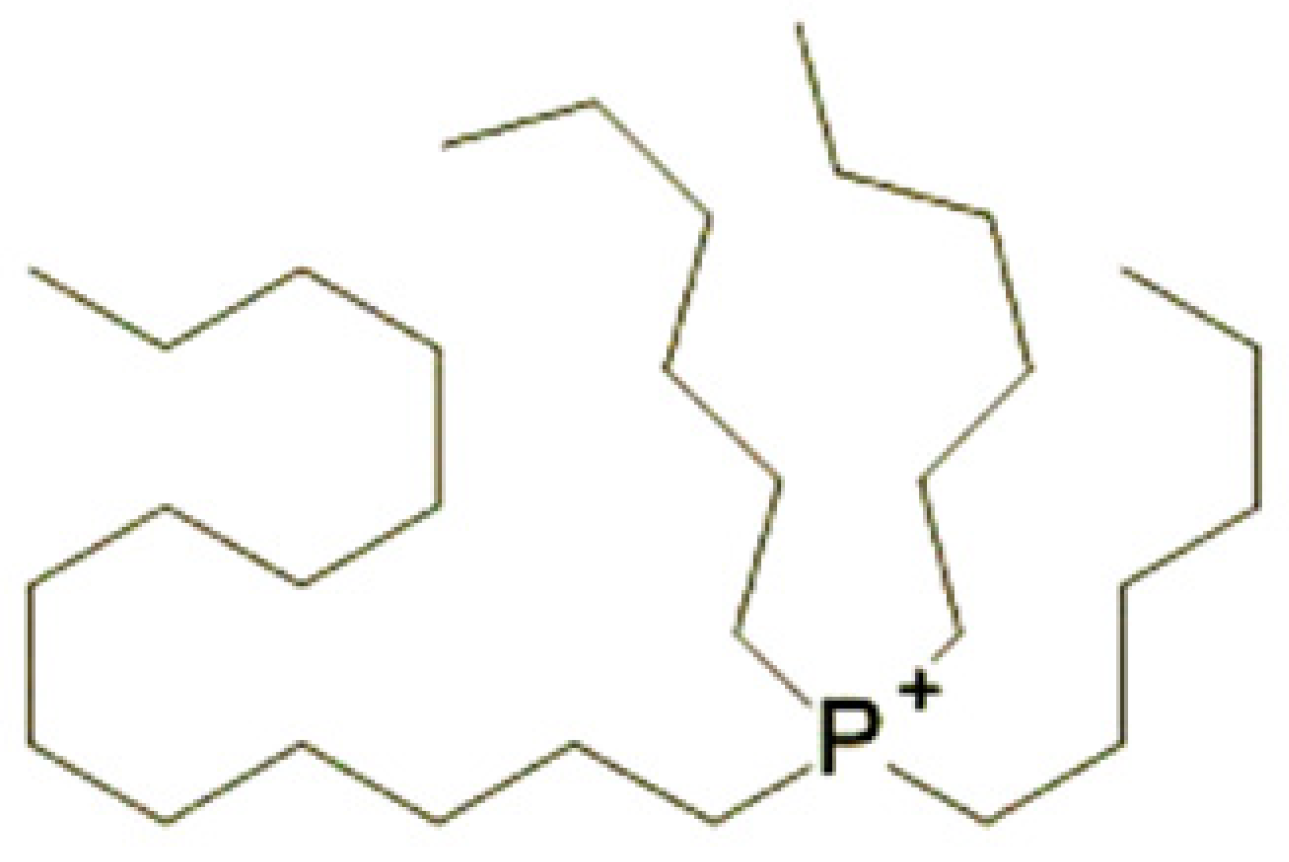
Bis(2-ethylhexyl)phosphate
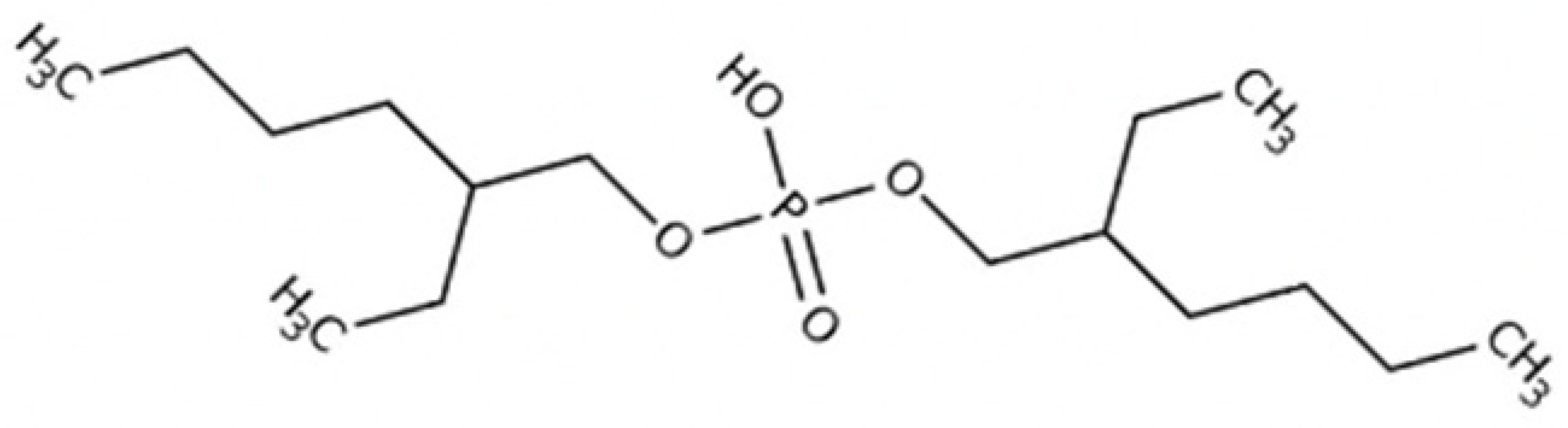
Lubricants 13 00209 i002
Kinematic Viscosity at 40 °C (mm2/s)528
Kinematic Viscosity at 100 °C (mm2/s)59
Viscosity Index181
Electrical Conductivity at 27 °C (µS/cm)0.19
Table 3. Electrical conductivity (κ) of the ATF and ATF + IL.
Temp. (°C)ATF
10−4 κ (μS/cm)
ATF + IL
10−4 κ (μS/cm)
2501.3
4003.8
802.56.9
1004.8711.3
1257.516.7
Table 4. Kinematic (ν) and dynamic (μ) viscosity of the ATF and ATK + IL.
Temp. (°C)ATF
μ (mPa·s)
ATF + IL
μ (mPa·s)
ATF
ν (mm2/s)
ATF + IL
ν (mm2/s)
2056.2556.16266.93166.84
4023.623.44628.51528.334
6011.98711.89714.70814.6
807.02646.96898.75718.6867
1004.57064.53095.7875.7379
Disclaimer/Publisher’s Note: The statements, opinions and data contained in all publications are solely those of the individual author(s) and contributor(s) and not of MDPI and/or the editor(s). MDPI and/or the editor(s) disclaim responsibility for any injury to people or property resulting from any ideas, methods, instructions or products referred to in the content.

