Article

Tribological Performance of Electrochemically Textured EN-GJS 400-15 Spheroidal Cast Iron

by
Peng Jiang
1,*,
Jonathon Mitchell-Smith
2 and
John Christopher Walker
1
1
National Centre for Advanced Tribology (nCATS), University of Southampton, Southampton SO17 1BJ, UK
2
TextureJet Ltd., Nottingham NG6 9FH, UK
*
Author to whom correspondence should be addressed.
Lubricants 2025, 13(5), 203; https://doi.org/10.3390/lubricants13050203
Submission received: 18 March 2025 / Revised: 29 April 2025 / Accepted: 30 April 2025 / Published: 2 May 2025
(This article belongs to the Special Issue Cast Iron as a Tribological Material)

Abstract

:
This paper presents an experimental study of uniform and variable texture patterns on a honed EN-GJS 400-15 spheroidal graphite cast iron surface. Textured samples were fabricated using a CNC electrochemical jet machining technique and tested against a 52100 G5 roller countersurface featuring a rectangular 1 mm × 13 mm contact area. Tribological tests were conducted in a fully flooded PAO4 lubricant bath at 30 °C on a TE-77 reciprocating sliding tribometer with a 25 mm stroke length. Frictional behaviour was assessed at test frequencies from 12 to 18 Hz under two loads, 11 N and 50 N, covering mixed and hydrodynamic lubrication regimes. Experimental results demonstrated that EJM textured surfaces were accurately fabricated within a ±2.50 µm standard error in depth, with chemical etching effects reducing the R q roughness of initial grinding marks by 0.223 µm. Textured surfaces exhibited a more pronounced friction performance at 50 N than at 11 N, exhibiting a consistent friction reduction of up to 18.8% compared to the untextured surface. The variable textured surface outperformed the uniform textured surface under the mixed lubrication regime due to the enhanced secondary lubrication effect. Optical and SEM analyses revealed that textured surfaces reduced plastic deformation and two-body abrasion.

1. Introduction

Surface texturing has emerged as a promising approach to improve the tribological performance of internal combustion engines (ICEs) since the early 20th century [1], particularly in the ring/liner assembly, which accounts for nearly 10% of total fuel consumption [2]. This method involves introducing engineered microfeatures on contact surfaces to enhance performance. The benefits of surface texturing in lubricated sliding contacts are well documented in the literature, including its role as a lubricant reservoir [3,4,5], trapping debris [6], and enhancing microhydrodynamic effects [7,8,9,10,11,12,13]. Pioneering research groups, such as those led by Etsion [9,13,14,15,16,17,18], Costa [19,20,21,22], and Reddyhoff [11,23,24,25,26,27,28,29], have extensively contributed to the understanding of surface texturing, focusing on its geometrical optimisation, friction reduction mechanisms, and fabrication techniques. However, empirical guidelines for surface texturing design remain elusive due to the variability in contact conditions [30,31], particularly in reciprocating sliding.
Given the oscillatory nature of ring/liner interaction in small-scale ICEs, lubrication transitions between hydrodynamic lubrication during the main stroke and mixed or boundary lubrication near the stroke ends must be considered for optimal surface texture design. Despite this, few studies have explored the potential of stroke-dependent variable texture patterns. Zhou et al. [32] developed a theoretical model incorporating conditions dependent on the crank angle, recommending optimal surface texture designs based on three regions along the cylinder. They recommended smaller features with lower texture density at the midstroke, with increasing feature size with densities toward the stroke ends. Similarly, Vlădescu et al. [26] proposed that larger volume features should be placed in the boundary lubrication regime and that narrower and more widely spaced features would be more suitable for other lubrication regimes.
Beyond geometric optimisation, selecting an appropriate surface texturing technique is crucial for ensuring functional effectiveness. Key factors include precision, repeatability, flexibility, cost, and productivity. Reviews by Coblas et al. [1] and Arslan et al. [33] summarised state-of-the-art texturing techniques, with laser surface texturing [9,25,34,35,36] and electrochemical etching [4,5,21,37,38,39,40,41] being the two most widely adopted methods for texturing metallic surfaces, owing to their ability to create well-defined continuous or discontinuous texture patterns [1]. Laser surface texturing utilises high-energy pulses to ablate targeted material via rapid melting and vaporisation [1,33]. While it offers high dimensional precision, it can also alter metallurgical properties and create heat-affected zones, which often necessitate post-processing [1,33]. Electrochemical etching, by contrast, circumvents these limitations by removing material through a chemical reaction between the substrate and a reactive agent [1,33]. However, traditional electrochemical methods require masking individual features on the workpiece, which can be inefficient and costly. Recent innovations [21,37,38,39,40,41] have overcome these limitations by enabling maskless localised machining.
Costa et al. [21] introduced a simple ‘maskless electrochemical texturing (MECT)’ method, demonstrating its high current efficiency for texturing metallic surfaces. Subsequently, Da Silva and Costa [38] employed this MECT technique to fabricate chevron-shaped texture patterns on grey cast iron, reporting improved friction and wear performance. Mitchell-Smith et al. [41] developed electrochemical jet machining (EJM), a high-precision and highly localised derivative of electrochemical machining, as illustrated in Figure 1. EJM does not require specialised tooling, as the jet itself serves as a cutting tool. The process employs compressed air to minimise electrolyte dispersion, ensuring precise material removal and improved feature definition. Walker et al. [4,5] successfully employed EJM on texturing Al–Si surfaces, achieving up to 38.5% and 37% friction reductions in mixed and fluid film lubrication regimes, respectively.
Cast iron is a durable and widely used material for cylinder liners in automotive applications due to its excellent machinability, mechanical properties, and cost efficiency [42,43,44,45,46]. Previous studies have demonstrated the effectiveness of textured cast iron liner surfaces in improving friction and wear performance by using MECT [38] and electrolyte jet machining [47,48]. However, the performance of variable texture patterns on honed liners remains insufficiently explored, especially under real engine load conditions. Additionally, the influence of material microstructure and surface roughness on texturing fabrication and operational performance is not well understood. To address this gap, this study applies EJM to EN-GJS 400-15 spheroidal graphite cast iron surfaces incorporating position-specific texture designs. Detailed surface analyses were performed to evaluate the feasibility of the EJM method, followed by reciprocating tribological testing to assess the frictional and wear behaviours of the textured surfaces under small-scale ICE load conditions.

2. Materials and Methods

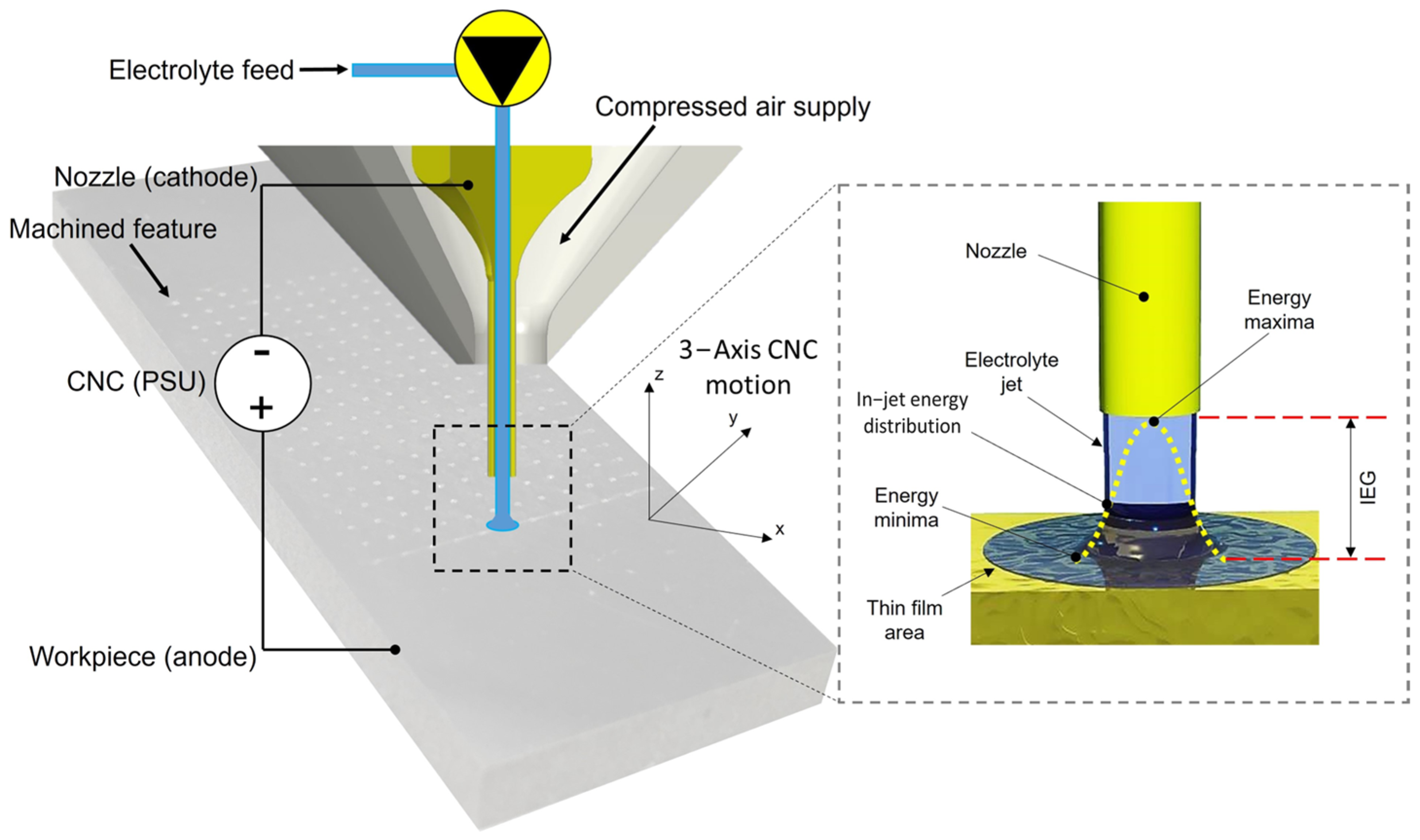
2.1. Sample Preparation

Coupon samples were made of EN-GJS 400-15 spheroidal graphite cast iron with the composition detailed in Table 1, a common material for engine blocks and liners in small-scale ICEs. A rectangular bar of 60 mm × 40 mm × 280 mm (West Yorkshire Steel Ltd., Leeds, UK) was sectioned into 5.45 mm thick test coupons using a Sodick SLC600G electro-discharge machine (Sodick Europe Ltd., Warwick, UK). The coupon surfaces were ground at a 45° angle relative to the length dimension to represent the honed patterns found on the cylinder liner of an ICE [43,44,45,46]. An AISI 52100 G5 finished cylindrical rolling bearing element with 6 mm diameter and 15 mm length (Atlas Ball & Bearing Ltd., Walsall, UK) was used to represent the top compression ring. Each cylindrical roller featured a 1 mm radius fillet at both ends to prevent pressure concentration effects at the edges, ensuring even load distribution at the contact interface. A 1 mm flat contact width was lapped on each roller using a 25 μm diamond suspension on a Kemet 15 lapping machine (Kemet International Ltd., Maidstone, UK), achieving a 13 mm2 flat countersurface that represented a conformal run-in ring surface condition.
A precision CNC EJM Texture Stat tool (TextureJet Ltd., Nottingham, UK) was employed to fabricate the designed texture patterns based on individual CAD models. The EJM process was controlled by the programmed parameters listed in Table 2. A NaCl electrolyte with a molar concentration of 2.3 mol/L, dissolved in deionised water, was jetted from a cathodic straight-walled stainless steel nozzle onto the anodic working area. The setup utilised a fixed current, which allowed a floating voltage due to the changing resistance caused by the inhomogeneous material structure of the workpiece, ranging between 0 and 150 V. This enabled selective anodic dissolution, facilitating the precise fabrication of dimensionally accurate features [41], as shown in Figure 1. Both uniform texture (UT) and variable texture (VT) patterns, with the parameters detailed in Table 3, were created using a bouncing tool path with a stand-off distance of 500 µm and a translation speed of 50 mm/min. This tool path allowed the end-effector to rapidly retract from the surface after completing the machining of each feature, quickly increasing resistance and thereby stopping any stray machining to maintain pattern precision [4]. It also enabled debris to be washed away before the tool rapidly descended to begin the next feature. As depicted in Figure 2, rectangular grooves oriented perpendicular to the reciprocating sliding direction were chosen for the design feature, which proved to be the most effective in recent studies [5,23,27]. Feature width was selected as the lower limit of the EJM technique to ensure full coverage by the countersurface, while the length was chosen to be 1.8 mm within a 2 mm × 2 mm texture cell area. The feature spacing design followed the principle used by Walker et al. [4], maintaining a spacing of five times the feature width. This resulted in a texture density of 18.9%, which is within the optimal range of 10–20% recommended in [30,31,50,51] for improving friction and wear performance in parallel reciprocating sliding contact under mixed and hydrodynamic lubrication regimes. The VT pattern altered feature depth as a function of stroke position, transitioning from an aspect ratio of 0.02 at the midstroke position to 0.04 at the stroke ends, as schematically represented in Figure 2.

2.2. Tribological Experiment
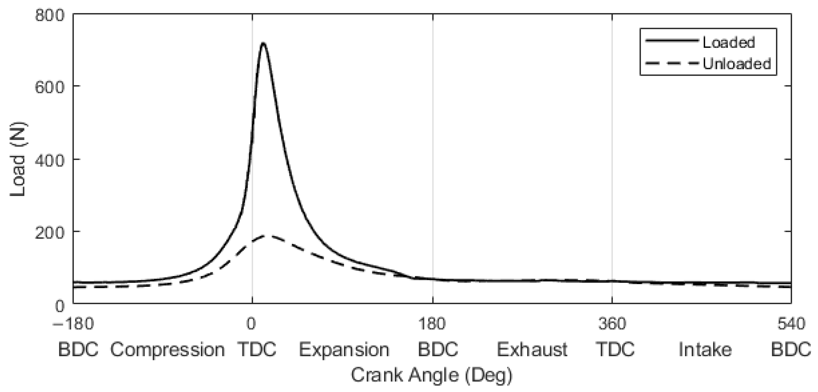
2.2.1. Testing Load

Tribological tests were conducted to evaluate the friction performance under contact pressures representative of those experienced by the top compression ring in a small-scale ICE, specifically the Honda GX200 engine (Honda Motor Ltd., Tokyo, Japan), under cold start conditions. Two engine ring radial loads were determined at 1600 rpm under unloaded and loaded operating conditions using RINGPAK Ricardo numerical engine simulations, following a methodology consistent with previous work [45]. The variations in the simulated ring radial load are plotted as a function of the crank angle in Figure 3. Since the ring radial load fluctuates with the crank angle due to gas pressure variations and stress concentrations, which lead to uneven load distribution across the ring surface, the largest ring radial load was chosen to represent extreme operating conditions. The peak loads were determined to be 188.6 N and 722.5 N for the unloaded and loaded states, respectively. To simulate these peak conditions in laboratory tribological testing, the loads were normalised based on the ratio of the countersurface contact area to the Honda engine ring contact area. This normalization ensured that the nominal contact pressures in the test setup closely reflected those under real engine operating conditions. Consequently, experimental loads of 11 N and 50 N were derived, corresponding to nominal contact pressures of 0.85 MPa and 3.85 MPa, respectively.

2.2.2. Tribological Testing

Tribological tests were conducted using a Phoenix Tribology TE-77 high-frequency reciprocating tribometer (Phoenix Tribology Ltd., Kingsclere, UK) to assess the friction performance of untextured and textured coupon samples under a lubricated rectangular contact configuration, as schematically illustrated in Figure 4. All tests were carried out using a stroke length of 25 mm under a normal load of 11 N or 50 N. Test samples were immersed in a fully flooded bath of 30 °C unformulated low viscosity synthetic oil polyalphaolefin (SpectraSyn 4 PAO, ExxonMobil Chemical Ltd., Fawley, UK) with a kinematic viscosity of 16.8 cSt at 40 °C and 3.8 cSt at 100 °C. The unformulated oil, which contains no additives, was chosen to ensure that the observed tribological behaviours were attributed solely to the surface texture, without compounding any influence of additives. Oil temperature was controlled primarily through an integrated heating system and a K-type thermocouple feedback loop. All samples were ultrasonically cleaned for 300 s in 60–80 petroleum ether prior to setup. The countersurface was positioned at the middle row of the texture pattern to maintain symmetrical distribution about the midstroke position, as depicted in Figure 4, such that the nominal initial contact pressure was determined to be 1.30 MPa at 11 N and 5.91 MPa at 50 N. These values increased compared to those over an untextured area due to the reduced real contact area introduced by the textured features. This initial arrangement prevented features from appearing at reversals, which negatively affect tribological performance due to oil film collapse, as reported by Vladescu et al. [23,26]. The 1 mm wide flat contact area was self-aligned to the flat coupon surface by registering the roller’s circumference against a perpendicular 3 mm pin that was part of the specimen clamping mechanism. Alignment parallel to the reciprocating sliding direction was achieved by adjusting the vertical position of the clamp before securing it tightly with two bolts. The roller’s back face would pivot on the pin for a correct self-alignment, which was assessed by a short duration test at a low frequency (~5 Hz) under a small load (5–10 N) before being clamped using the grub screw under a high load of 200 N. Each test was programmed to be started with a run-in process at 12 Hz frequency for 1800 s under the specified testing load to ensure surface conformity and stabilisation of initial tribological interactions. This duration was selected based on preliminary trials, which showed stabilisation in the coefficient of friction within the timeframe. Each test was then followed by an increment to 18 Hz at 1 Hz intervals, with a dwell time of 300 s at each frequency, transitioning into the hydrodynamic lubrication regime. The rms average friction force was acquired every second using a low-speed interface, while high-speed instantaneous data (friction force and contact potential) as a function of stroke length were recorded for 5 s after sliding at each frequency. The sampling frequency of the high-speed data was set to 12 kHz at a test frequency of 12 Hz, with an increment of 1 kHz for each increase in test frequency. The coefficient of friction was calculated in real time as the ratio of the measured friction force to the applied normal load using the TE-77 control software (COMPEND 2000). Each tribological test was repeated twice to ensure the repeatability and reliability of the results.

2.2.3. Surface Analysis

Samples were cleaned in an ultrasonic bath filled with petroleum ether 60–80 solvent for 5 min to remove testing oil, dust, and wear debris before conducting any surface analysis. A noncontact optical surface profilometer (Alicona InfiniteFocus G4 focus variation microscope, Bruker Alicona, Raaba, Austria) was used to examine surface topography, including the analysis of surface roughness and dimensional parameters of the textured patterns. A minimum of five randomly selected profiles were analysed for each acquired 3D surface map, and average values and standard deviations were calculated across the multiple profiles to minimise local variations. For roughness measurements, extracted profiles, generated by averaging over a 10 µm bandwidth, were oriented perpendicular to the grinding marks on coupon surfaces and perpendicular to the sliding direction on countersurfaces. Roughness was evaluated in accordance with ISO 4287 [52] using a Gaussian filter (ISO 16610-21 [53]) with a cutoff wavelength of 0.8 mm and a minimum evaluation length of 4 mm. This standard filtering approach was applied automatically by the instrument, with no additional form or waviness filters beyond these settings. A higher magnification analysis of particular texture features and wear characteristics was performed on the UT and VT surfaces using a JEOL JSM-7200F field-emission gun scanning electron microscope (FEG–SEM; JEOL Ltd., Akishima, Japan).

3. Results and Discussion

3.1. Surface Topography

3.1.1. Untextured Surface

The optical microscope image in Figure 5a shows the initial untextured ground cast iron surface, where the parallel grinding marks were machined at a 45° angle relative to the horizontal sliding direction. These grinding marks were evenly distributed across the surface, as confirmed by the 3D colour height map in Figure 5b. The average surface roughness parameters, measured perpendicular to the grinding marks, were determined to be 1.250 ± 0.036 µm for R a , 1.681 ± 0.034 µm for R q , and 10.087 ± 0.630 µm for R z .

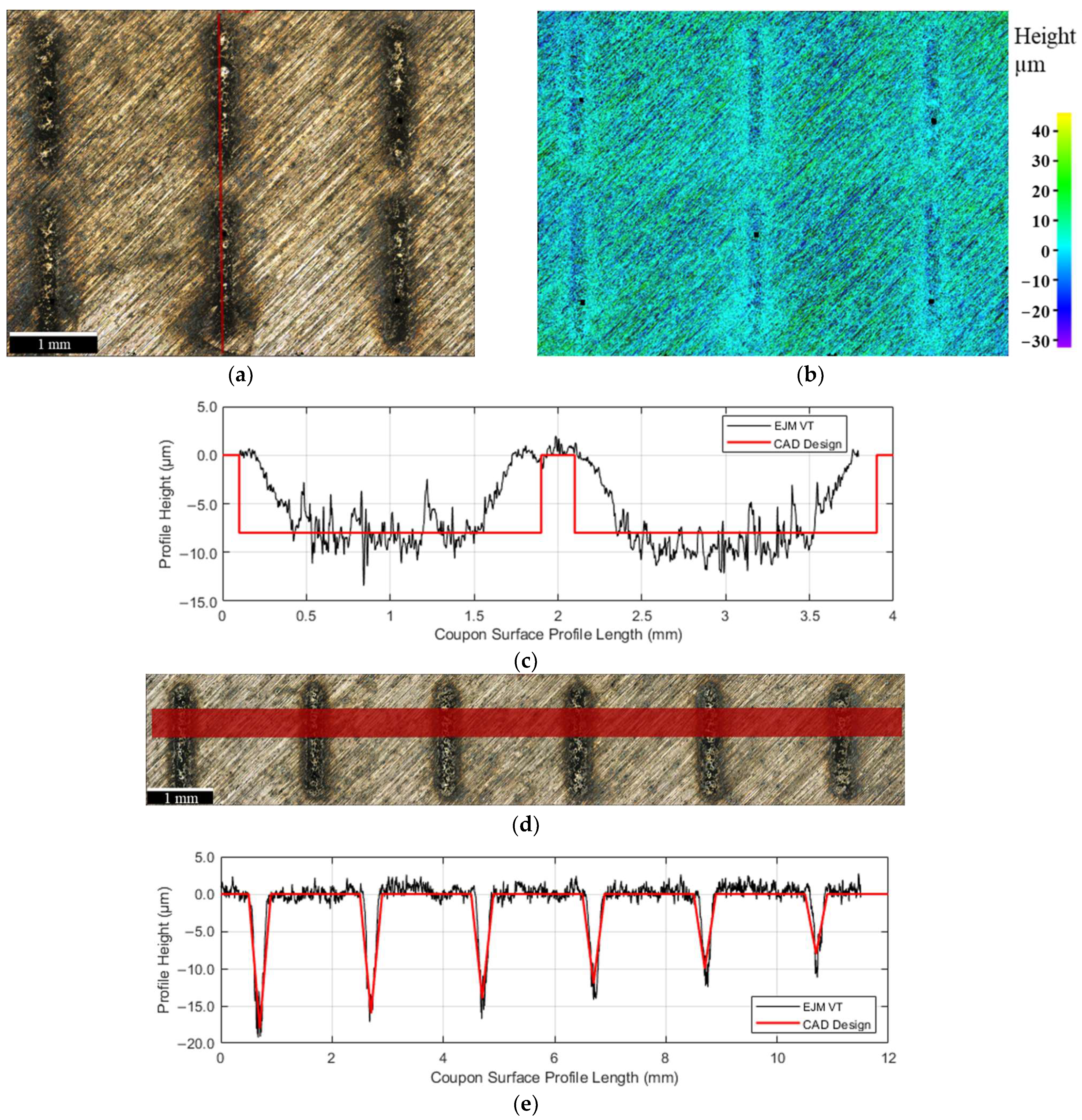
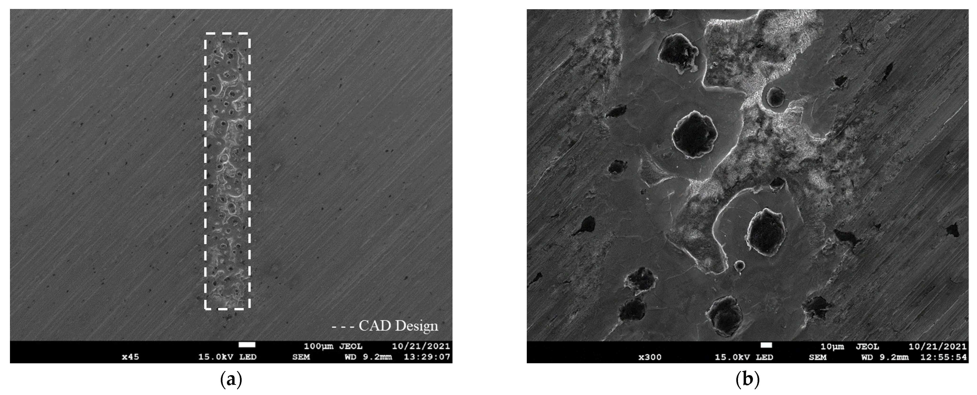
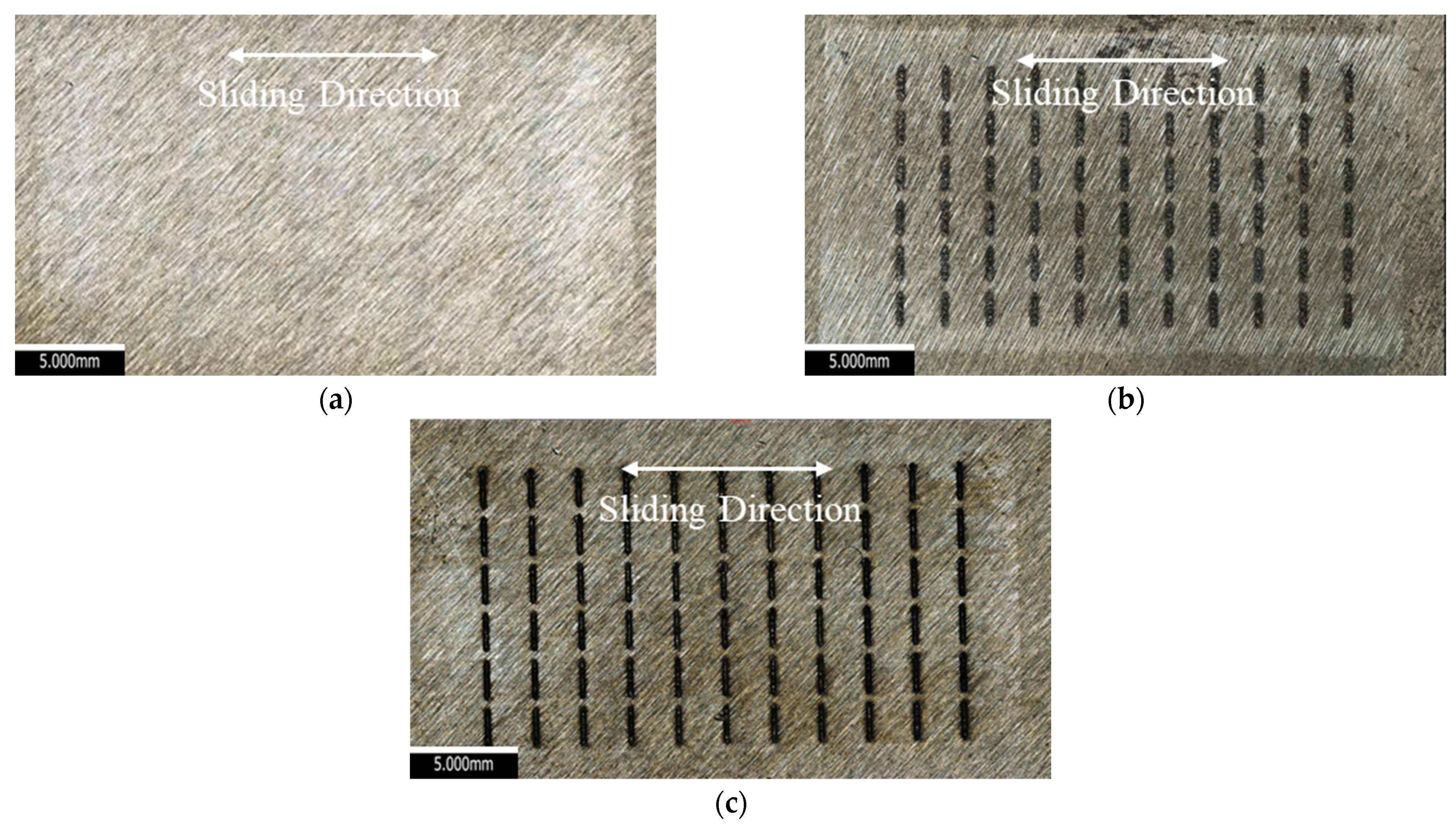
3.1.2. Textured Surface

The optical observations and measured primary profiles from the VT surface are presented in Figure 6. Optical images in Figure 6a,d reveal that the EJM process removed the topography at the features, resulting in darker regions, due to the selective dissolution of the ferritic iron matrix. The topography changes are also reflected in the 3D colour height map in Figure 6b. The textured surface showed none of the thermal effects, burs, or lips around the edges of features that are common with laser-textured features. These findings were further confirmed by the secondary electron images in Figure 7. The average R q roughness on the textured surface, excluding the features, was measured at 1.458 ± 0.032 µm, indicating that EJM reduced the surface roughness by 0.223 µm.
The geometrical dimensions and distribution of the textured pattern were analysed using primary profiles measured from defined red bands in the optical images, as shown in Figure 6c,e. All measurements with calculated standard deviations are tabulated in Table 3. Both profiles exhibited local variations in dimensions, particularly at the bottom surfaces of features, resulting from the spheroidal graphite phase.
The geometrical characteristics of the EJM textured features were also compared with the CAD design. In Figure 6c, in addition to the local dimensional variations, edge gradients were observed within the designed rectangular internal shape, resulting in a total area difference of 20.07%. This discrepancy is attributed to the spatial variation in dissolution rates influenced by the in-jet field potential energy distribution from the cylindrical nozzle, which exhibits characteristics similar to the Gaussian distribution in intensity [39,40]. Figure 6e shows that the EJM process accurately reproduced the designed VT texture pattern along the X-axis, with feature depths decreasing from the stroke end (left) to the midstroke (right). An average standard depth deviation of 2.50 µm from the design specification was determined.
Higher magnification SEM imaging was conducted on an 8 µm deep feature of the VT surface, as shown in Figure 7. The EJM allowed anodic dissolution of the alpha ferrite phase without inducing thermal effects on the metallurgical structure surrounding the textured feature, which are common phenomena associated with the ablative processes of metallic materials [4,5]. This absence of localised anisotropy prevents unwanted changes in the microstructure due to rapid solidification or tempering, eliminating the need for additional post-processing to remove surface protrusions that might disrupt lubricant films. The predominantly carbon-depleted ferritic structure was dissolved around retained spheroidal graphite, with the selective dissolution of the ferritic component of pearlite resulting in fibrous cementite present further away from the spheroidal graphite. Due to the compositional segregation of carbon during spheroidal solidification, the resulting ferritic–pearlitic matrix exhibited grain sizes exceeding 10 µm. An averaged R q roughness was measured at 2.583 ± 0.056 µm within the feature. EJM on the textured region slightly altered the continuously distributed grinding grooves, particularly around the features, though dissolution effects did not extend significantly beyond the immediate texture regions, retaining ground topography. This was due to the nozzle dissipating high current density electrolytes around the features, as the process continuously developed, both alongside and between features, ensuring controlled material removal during workpiece translation.

3.2. Tribological Results

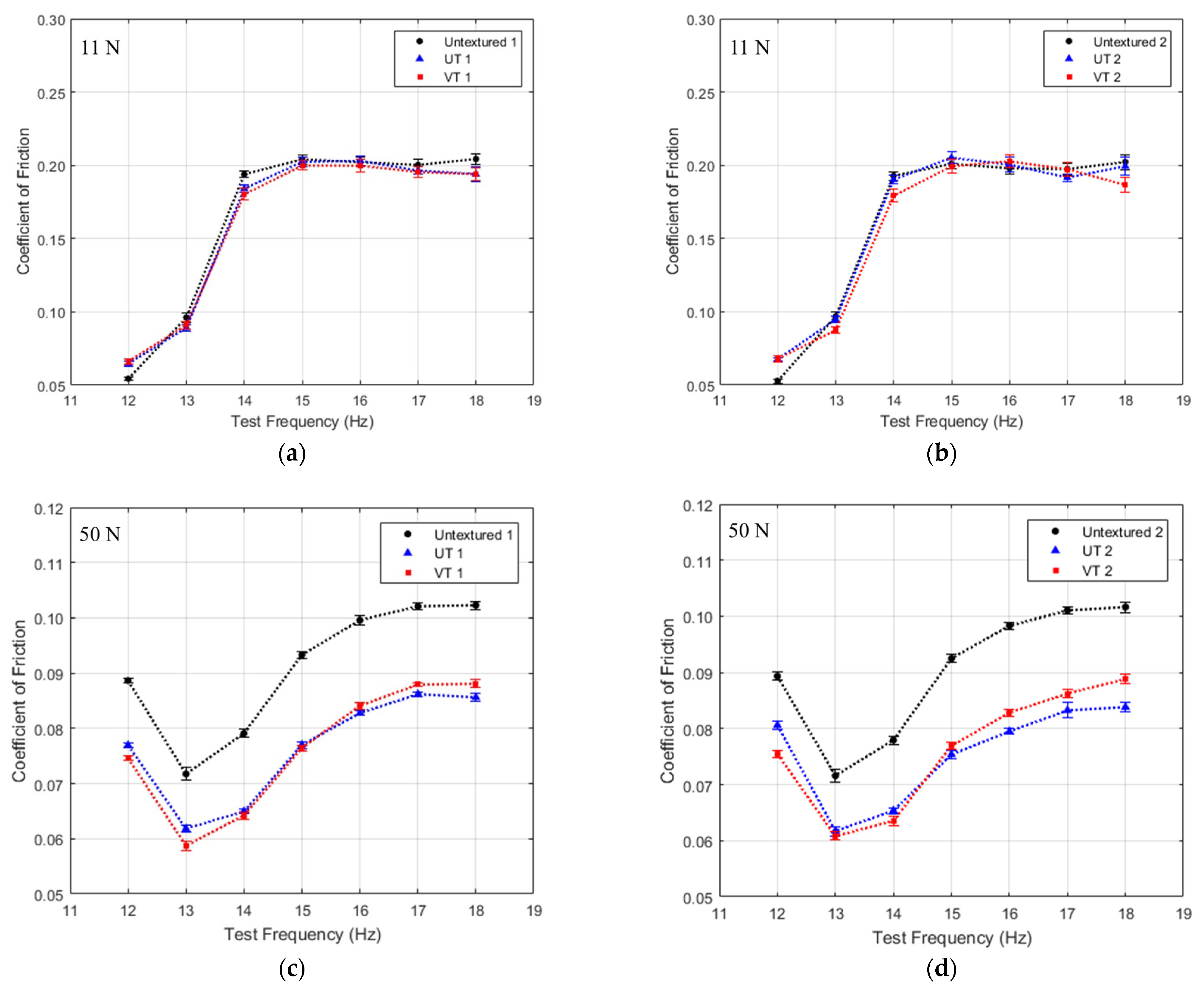
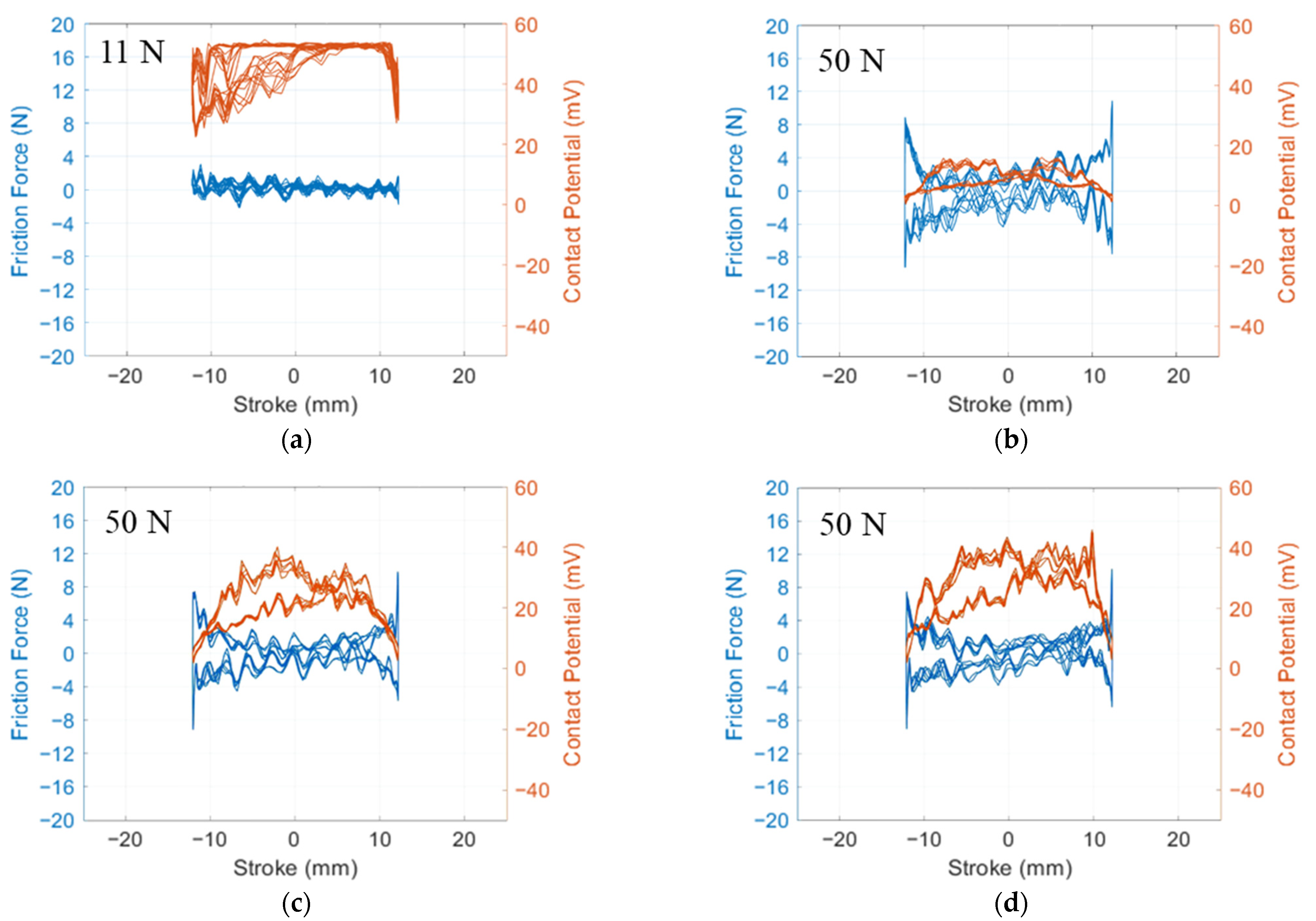
3.2.1. Friction Behaviour

The average coefficients of friction from the untextured, UT, and VT surface tests were plotted over the reciprocating test frequency conditions, as shown in Figure 8. Standard deviation error bars are included to illustrate the data variability, calculated from 270–280 measurements at each reciprocating frequency. Dotted lines are plotted to distinguish the results from each sample. The average differences in the repeated experimental results yielded deviations of 3%, 5%, and 4% for the untextured, UT, and VT surfaces, respectively. These deviations indicate that the measurements for each surface type exhibit low variability, confirming the repeatability and reliability of the experimental conditions and the test setup.
For the 11 N tribological tests, the frequency-dependent gradients of each result indicate that the tests were conducted within the hydrodynamic lubrication regime, as shown in Figure 8a,b. Both UT and VT surfaces showed no significant improvements in friction across all test frequencies, as the lubricant film was sufficiently thick to provide the necessary fluid pressure to support the applied load, rendering surface textures less influential.
When the test load increased to 50 N, the lubricant film thickness at the contact interface decreased, leading to a reduction in the contact potential signal over the stroke, as shown in Figure 9a,b. The friction behaviour in Figure 8c,d indicates a lubrication regime transition from mixed lubrication to hydrodynamic lubrication between 13 and 14 Hz. Both UT and VT surfaces exhibited consistent friction reductions compared to the untextured surface, with maximum reductions of 17.9% and 18.8% at 14 Hz, respectively. These findings validate that the groove features were oriented perpendicular to the sliding direction, effectively reducing friction, which is consistent with previous studies [5,23,27].
In the mixed-lubrication regime at low frequencies (12 and 13 Hz), the primary friction reduction mechanism was the secondary lubrication effect for both textured surfaces. The textured features served as lubricant reservoirs, supplying additional lubricant to the contact area when the lubricant was squeezed out under pressure, thereby reducing asperity contact and overall friction. The improved lubricant retention and thicker film thickness for both textured surfaces, compared to the untextured surface, were indicated by higher instantaneous contact potential values throughout the stroke, as shown in Figure 9b–d. The average instantaneous contact potential values were determined to be 16.5 ± 2.3 mV, 29.3 ± 5.0 mV, and 33.1 ± 3.4 mV for the untextured, UT, and VT surfaces, respectively. Additionally, the average friction forces around midstroke were determined to be 1.56 ± 0.74 N, 0.79 ± 0.66 N, and 0.95 ± 0.68 N, confirming the superior performance of the textured surfaces. The secondary friction reduction mechanism was attributed to a decreased contact area due to the presence of texture features [54], which was particularly beneficial near the stroke ends, where the mixed and boundary lubrication regimes dominated. A comparison of the two textured surfaces revealed that the VT surface provided a slight advantage in film formation, particularly near the stroke ends. At these positions, the VT surface exhibited a lower average friction force of 2.76 ± 1.38 N, compared to 3.14 ± 1.56 N for the UT surface. This friction reduction is attributed to the enhanced localised secondary lubrication effect, which is facilitated by the deeper groove features on the VT surface. These findings are consistent with the recommended design criteria outlined in [26,32].
As the tests progressed into the hydrodynamic lubrication regime, the previously mentioned friction reduction mechanisms remained effective, whilst hydrodynamic effects became more dominant due to thicker lubricant films resulting from higher stroke velocities. This transition was particularly noticeable when a single feature was fully covered by the contact area, as discussed by Walker et al. [5], regarding the influence of contact area on sliding tribological performance. Moreover, the enhanced entrainment effect and possible inlet suction phenomena within the parallel contact region contributed to thicker lubricant films [55], leading to a higher hydrodynamic support load and further friction reduction. This effect was corroborated by the evidence of localised wear around feature edges, as shown in the SEM images in the following section. As the test frequency increased and a hydrodynamic lubrication regime consequently expanded over the stroke, the UT surface exhibited greater friction reduction compared to the VT surface, due to a stronger hydrodynamic effect. This was because uniform shallow features were more effective at generating higher net positive film pressure in this lubrication condition, a behaviour that aligns with the numerical study by Vilhena et al. [56] and other experimental findings [57,58,59].

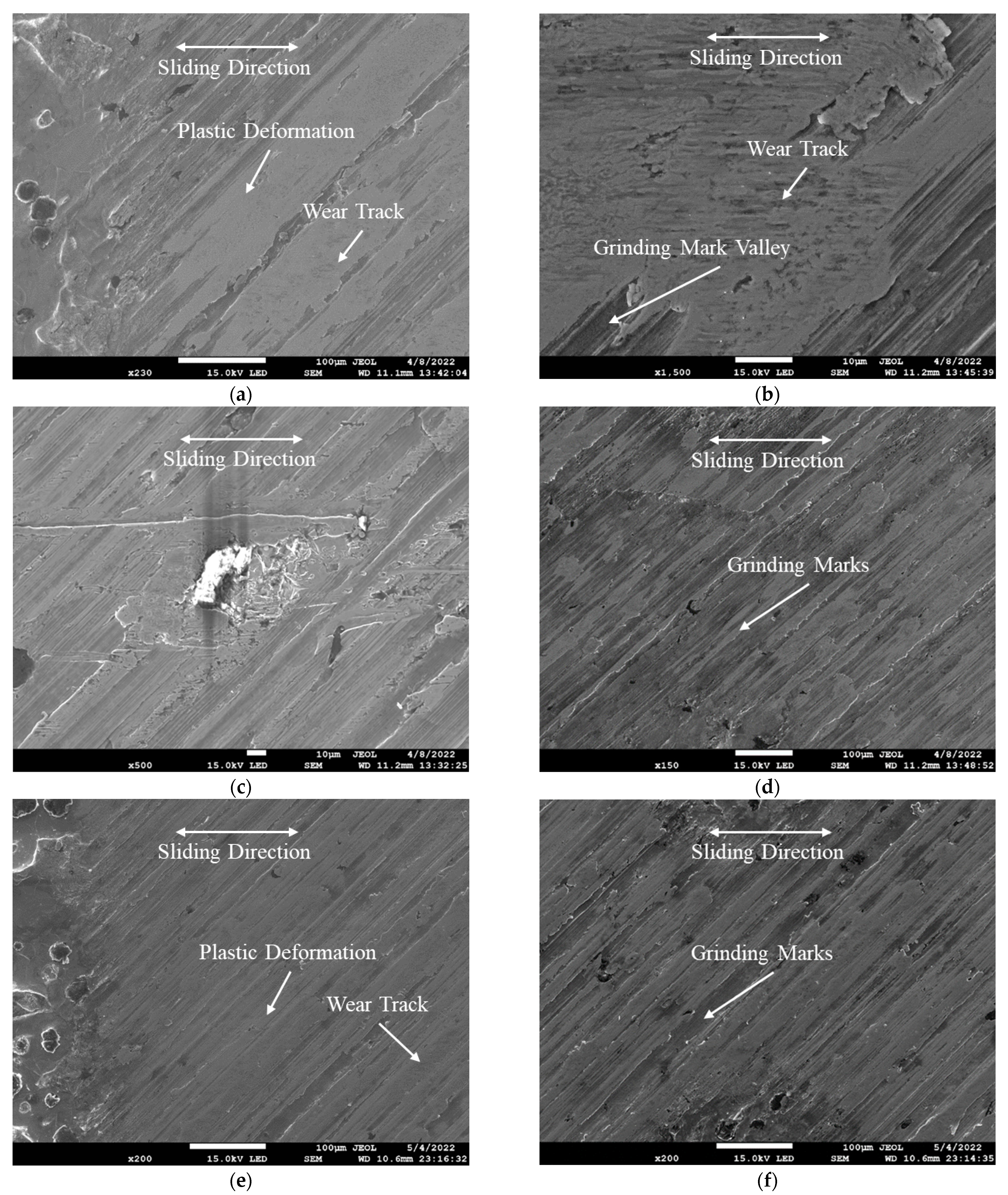
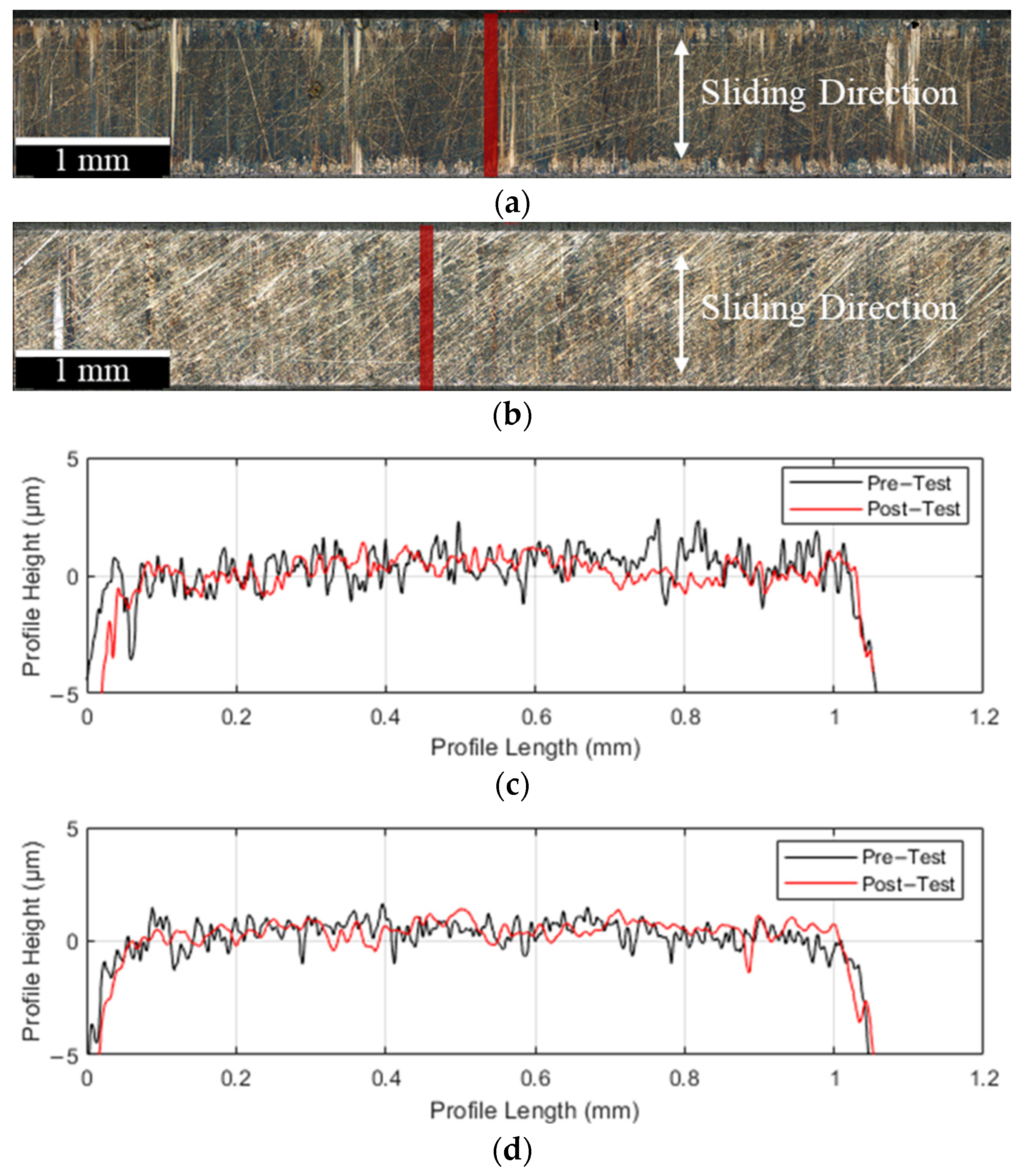
3.2.2. Coupon Surface Analysis

Optical images of the untextured, UT and VT surfaces after the 50 N tribological testing, as shown in Figure 10, revealed that each wear scar was symmetrically distributed about the midstroke position. The length of each wear scar was measured at slightly over 26 mm, confirming that proper parallel alignment between the coupon and countersurface was achieved during each test. Discontinuities observed in all wear scars along the sliding direction were attributable to positional variations in instantaneous stroke velocities. This was corroborated by the lower average R q roughness near the stroke ends compared to the midstroke position, as indicated in Table 4. For both textured surfaces, the wear scars extended beyond the textured features, preventing any detrimental effects at stroke reversals [23,26].
Slight decreases in average R q were observed on the untextured and textured surfaces after the 11 N tribological tests, suggesting minimal surface damage and polishing-type wear. These roughness changes further indicated that the wear-reducing benefit of textured surfaces was marginal at the 11 N test load, consistent with the observed friction behaviours. In contrast, more pronounced wear occurred during the 50 N sliding tests, indicating that the load had a significant impact on sliding wear [60]. Both textured surfaces demonstrated reduced wear compared to the untextured surface, particularly near the stroke reversals, as evidenced by smaller roughness changes. This reduction is primarily attributed to lubricant film enhancement, as discussed in the friction behaviour analysis.
Secondary electron imaging was performed on the worn UT surface (Figure 11a–d) and VT surface (Figure 11e,f) near the stroke reversals following the 50 N tribological tests, where the most significant damage appeared. Both textured surfaces exhibited plastic deformation of the ground surface and visible wear tracks around the textured features. The plastic deformation of the top surface layers led to the agglomeration of removed wear debris within the valleys of the ground marks, as demonstrated in Figure 11b. This wear process reduced the ground surface asperity peaks, resulting in a worn surface resembling the run-in plateau characteristic of honed engine cylinder liners. The observed wear tracks, particularly those observed in Figure 11c, are characteristic of a two-body abrasion mechanism. In addition, the presence of plastic extrusion features within the wear morphologies, especially around the ground asperity peaks, suggests that plastic ratcheting wear may also have contributed to the wear process [61,62]. Repeated sliding under load could have induced localised cyclic plastic deformation, leading to material extrusion. Interestingly, greater damage was observed at the feature edges (Figure 11a,e) compared to the regions between features (Figure 11d,f) on both textured surfaces. This difference results from reduced plastic deformation and two-body abrasion when the countersurface passes over a row of textured features, benefiting from the secondary lubrication effect. Although the VT surface demonstrated slightly improved friction and wear performance near the stroke reversals, it exhibited wear characteristics similar to the UT surface. No evidence of adhesive transfer from the countersurface was detected, which aligns with expectations for these tests under low contact pressure conditions.

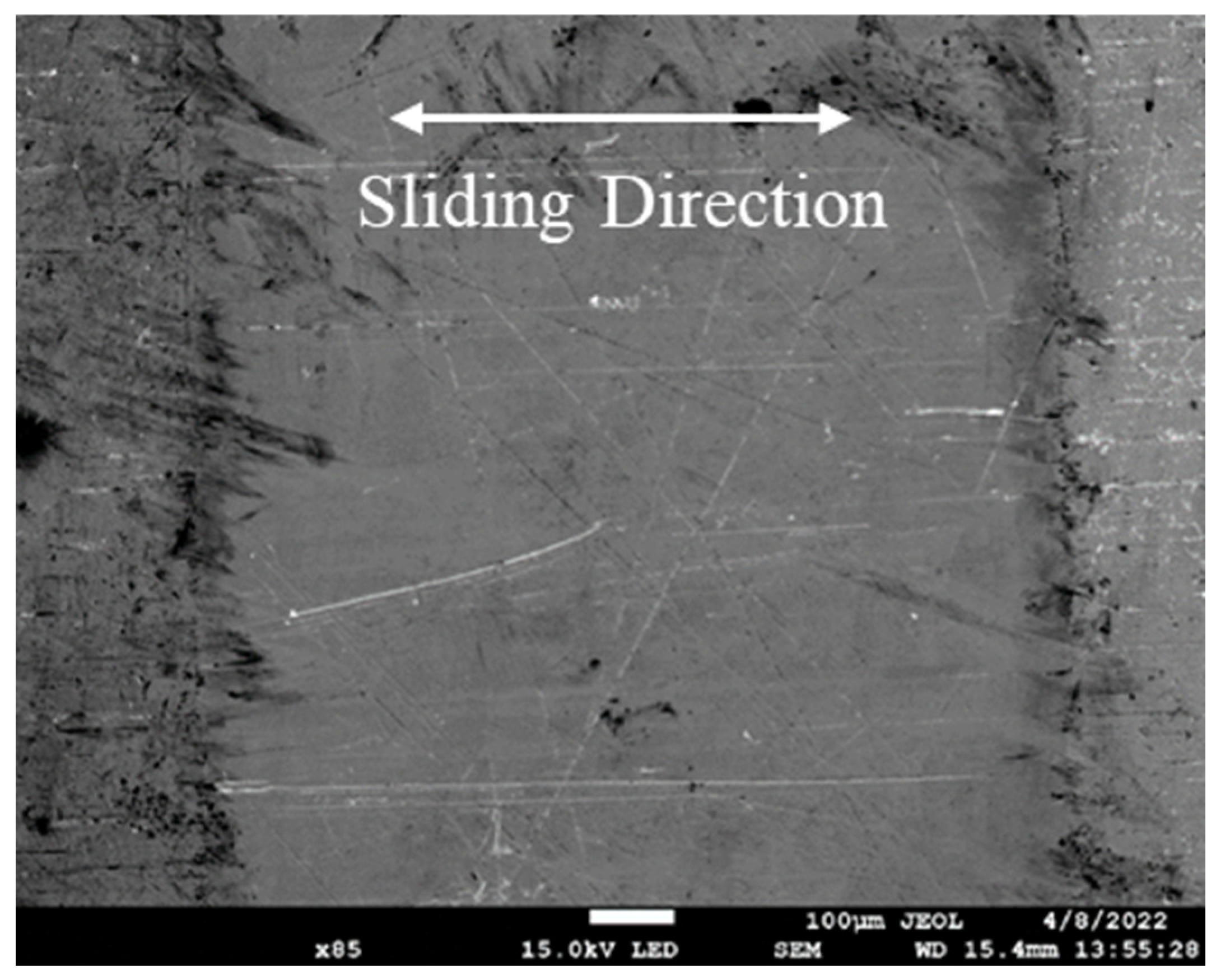
3.2.3. Countersurface Analysis

Figure 12a,b show optical images of the worn AISI 52100 countersurfaces after 50 N tribological tests against the untextured and textured samples. Wear tracks extended across the entire countersurface parallel to the sliding direction, suggesting minimal damage on both surfaces. Primary surface profiles were extracted over the defined red bands along the sliding direction, as shown in Figure 12c,d, revealing no noticeable increase in contact width after testing. This indicates that no significant wear-induced changes occurred in the rectangular contact area, which is crucial in dynamic pressure sliding, as changes in the contact geometry could influence the contact pressures. The average R q roughness values, measured perpendicular to the sliding direction, were 0.564 ± 0.022 µm and 0.414 ± 0.018 µm for the countersurfaces tested against untextured and textured samples, respectively, increasing from an initial mean value of 0.361 ± 0.034 µm. The smaller roughness increase on the countersurface, tested against the textured samples, indicated reduced wear. Additionally, a secondary electron image of this countersurface, shown in Figure 13, confirmed that the abrasion wear characteristics were due to a two-body abrasion mechanism with no observable material transfer. These findings reinforce the effectiveness of surface texturing in reducing overall wear in reciprocating tribological contacts.

4. Summary

The EJM technique successfully fabricated both UT and VT patterns on honed EN-GJS 400-15 spheroidal graphite cast iron surfaces featuring machined 45° grinding marks. The process produced dimensionally accurate features without burs or lip formation, eliminating the need for additional post-processing. This is particularly advantageous for honed cylinder liners, as post-processing could compromise the integrity of the original honing structures. Selective dissolution of the alpha ferrite phase during EJM exposed the spheroidal graphite, contributing to increased roughness at the feature bottoms. Comparisons with EJM textured surfaces on A390 alloy [4] confirmed that the resulting surface topography is material-dependent, influenced by material composition, microstructure, and grain size variability. EJM slightly modified the continuity of the initial grinding grooves, reducing overall surface roughness. Despite localised roughness changes, no significant adverse effects on friction performance were observed.
Tribological tests were conducted on the untextured and EJM-textured spheroidal graphite cast iron surfaces under lubricated area contact conditions at two normalised ring loads, 11 N and 50 N, to evaluate friction and wear behaviour using an unformulated low viscosity lubricant (PAO4). At the lower load (11 N), no significant improvement in friction was observed on the textured surfaces, as a sufficiently thick lubricant film under hydrodynamic conditions limited the influence. Surface analysis revealed only slight surface roughness changes across all samples, indicating minimal surface damage and a polishing-type wear mechanism. However, under the higher test load (50 N), both UT and VT surfaces exhibited consistent friction reduction compared to the untextured surface. The textured surfaces also demonstrated noticeable wear reduction, particularly near stroke reversal positions, attributed to enhanced lubricant film formation. Secondary electron imaging supported these findings, showing plastic deformation and two-body abrasion marks, primarily at feature edges, with less wear observed between features. The VT surface showed improved film thickness and enhanced secondary lubrication effects near the stroke reversals owing to its larger feature volume [5]. In contrast, the UT surface exhibited a lower friction coefficient in the full-film regime due to the more effective hydrodynamic effect resulting from its shallower features.
These results demonstrate the potential of EJM-textured VT patterns for cylinder liner application while also underscoring the strong dependence of surface texturing performance on load, operating frequency, and lubrication conditions.

5. Conclusions

This study investigated the application of EJM for fabricating complex groove patterns on EN-GJS 400-15 spheroidal graphite cast iron and evaluated their tribological performance under simulated engine ring operating conditions. The following key conclusions were drawn:
  • EJM effectively produced precise uniform and variable groove patterns on cast iron surfaces without introducing thermal effects, burs, or lip formation.
  • The selective dissolution process altered the surface topography, indicating that the final surface characteristics are influenced by the material composition, microstructure, and grain size.
  • Textured surfaces exhibited a greater friction reduction at 50 N than at 11 N, with a consistent decrease of up to 18.8%.
  • Optical and SEM analyses confirmed that plastic deformation and two-body abrasion were the primary wear mechanisms. Textured surfaces reduced wear by enhancing secondary lubrication and hydrodynamic effects.
  • The VT surface proved more effective than the UT surface in reducing friction and wear under the mixed lubrication regime due to an improved secondary lubrication effect.
  • Countersurface analysis revealed reduced wear when sliding against textured specimens, showing less two-body abrasion and no observable material transfer.

Author Contributions

Conceptualization, P.J. and J.C.W.; Methodology, P.J., J.M.-S., and J.C.W.; Software, P.J.; Validation, P.J. and J.C.W.; Formal Analysis, P.J.; Investigation, P.J., J.M.-S., and J.C.W.; Resources, P.J. and J.C.W.; Data Curation, P.J.; Writing—Original Draft Preparation, P.J.; Writing—Review & Editing, P.J., J.M.-S., and J.C.W.; Visualization, P.J.; Supervision, J.C.W.; Project Administration, J.C.W. All authors have read and agreed to the published version of the manuscript.

Funding

This research received no external funding.

Data Availability Statement

The data presented in this study are available on request from the corresponding author.

Acknowledgments

The authors would like to thank Ricardo for providing access to the RINGPAK suite of numerical modelling software.

Conflicts of Interest

Author Jonathon Mitchell-Smith is employed by Texture Jet Ltd. The remaining authors declare that the research was conducted in the absence of any commercial or financial relationships that could be construed as a potential conflict of interest.

References

  1. Coblas, D.G.; Fatu, A.; Maoui, A.; Hajjam, M. Manufacturing textured surfaces: State of art and recent developments. Proc. Inst. Mech. Eng. Part J J. Eng. Tribol. 2014, 229, 3–29. [Google Scholar] [CrossRef]
  2. Wong, V.W.; Tung, S.C. Overview of automotive engine friction and reduction trends–Effects of surface, material, and lubricant-additive technologies. Friction 2016, 4, 1–28. [Google Scholar] [CrossRef]
  3. Wakuda, M.; Yamauchi, Y.; Kanzaki, S.; Yasuda, Y. Effect of surface texturing on friction reduction between ceramic and steel materials under lubricated sliding contact. Wear 2003, 254, 356–363. [Google Scholar] [CrossRef]
  4. Walker, J.C.; Kamps, T.J.; Lam, J.W.; Mitchell-Smith, J.; Clare, A.T. Tribological behaviour of an electrochemical jet machined textured Al-Si automotive cylinder liner material. Wear 2017, 376–377, 1611–1621. [Google Scholar] [CrossRef]
  5. Walker, J.C.; Cinti, S.; Kamps, T.J.; Mitchell-Smith, J.; Clare, A.T. Influence of contact area on the sliding friction and wear behaviour of an electrochemical jet textured Al-Si alloy. Wear 2019, 426–427, 1336–1344. [Google Scholar] [CrossRef]
  6. Varenberg, M.; Halperin, G.; Etsion, I. Different aspects of the role of wear debris in fretting wear. Wear 2002, 252, 902–910. [Google Scholar] [CrossRef]
  7. Li, K.; Jing, D.; Hu, J.; Ding, X.; Yao, Z. Numerical investigation of the tribological performance of micro-dimple textured surfaces under hydrodynamic lubrication. Beilstein J. Nanotechnol. 2017, 8, 2324–2338. [Google Scholar] [CrossRef]
  8. Fesanghary, M.; Khonsari, M.M. On the optimum groove shapes for load-carrying capacity enhancement in parallel flat surface bearings: Theory and experiment. Tribol. Int. 2013, 67, 254–262. [Google Scholar] [CrossRef]
  9. Etsion, I. Improving Tribological Performance of Mechanical Components by Laser Surface Texturing. Tribol. Lett. 2004, 17, 733–737. [Google Scholar] [CrossRef]
  10. Yu, H.; Wang, X.; Zhou, F. Geometric Shape Effects of Surface Texture on the Generation of Hydrodynamic Pressure Between Conformal Contacting Surfaces. Tribol. Lett. 2009, 37, 123–130. [Google Scholar] [CrossRef]
  11. Vlădescu, S.-C.; Medina, S.; Olver, A.V.; Pegg, I.G.; Reddyhoff, T. The Transient Friction Response of a Laser-Textured, Reciprocating Contact to the Entrainment of Individual Pockets. Tribol. Lett. 2016, 62, 19. [Google Scholar] [CrossRef]
  12. Ghani, J.A.; Mohd Nasir, F.F.; Rahman, H.A.; Hakim Wan Zamri, W.F.; Kasim, M.S.; Muhamad, S.S. Computational fluid dynamic analysis on tribological performance under hydrodynamic lubrication of dimple textured surface produced using turning process. Wear 2021, 477, 203898. [Google Scholar] [CrossRef]
  13. Ronen, A.; Etsion, I.; Kligerman, Y. Friction-Reducing Surface-Texturing in Reciprocating Automotive Components. Tribol. Trans. 2001, 44, 359–366. [Google Scholar] [CrossRef]
  14. Etsion, I.; Burstein, L. A Model for Mechanical Seals with Regular Microsurface Structure. Tribol. Trans. 1996, 39, 677–683. [Google Scholar] [CrossRef]
  15. Etsion, I.; Kligerman, Y.; Halperin, G. Analytical and Experimental Investigation of Laser-Textured Mechanical Seal Faces. Tribol. Trans. 1999, 42, 511–516. [Google Scholar] [CrossRef]
  16. Etsion, I. State of the Art in Laser Surface Texturing. J. Tribol. 2005, 127, 248–253. [Google Scholar] [CrossRef]
  17. Etsion, I.; Sher, E. Improving fuel efficiency with laser surface textured piston rings. Tribol. Int. 2009, 42, 542–547. [Google Scholar] [CrossRef]
  18. Etsion, I. Modeling of surface texturing in hydrodynamic lubrication. Friction 2013, 1, 195–209. [Google Scholar] [CrossRef]
  19. Bruzzone, A.A.G.; Costa, H.L.; Lonardo, P.M.; Lucca, D.A. Advances in engineered surfaces for functional performance. CIRP Ann. 2008, 57, 750–769. [Google Scholar] [CrossRef]
  20. Costa, H.L.; Hutchings, I.M. Hydrodynamic lubrication of textured steel surfaces under reciprocating sliding conditions. Tribol. Int. 2007, 40, 1227–1238. [Google Scholar] [CrossRef]
  21. Costa, H.L.; Hutchings, I.M. Development of a maskless electrochemical texturing method. J. Mater. Process. Technol. 2009, 209, 3869–3878. [Google Scholar] [CrossRef]
  22. Costa, H.L.; Hutchings, I.M. Some innovative surface texturing techniques for tribological purposes. Proc. Inst. Mech. Eng. Part J J. Eng. Tribol. 2014, 229, 429–448. [Google Scholar] [CrossRef]
  23. Vladescu, S.-C.; Olver, A.V.; Pegg, I.G.; Reddyhoff, T. The effects of surface texture in reciprocating contacts—An experimental study. Tribol. Int. 2015, 82, 28–42. [Google Scholar] [CrossRef]
  24. Vlădescu, S.-C.; Medina, S.; Olver, A.V.; Pegg, I.G.; Reddyhoff, T. Lubricant film thickness and friction force measurements in a laser surface textured reciprocating line contact simulating the piston ring–liner pairing. Tribol. Int. 2016, 98, 317–329. [Google Scholar] [CrossRef]
  25. Vlădescu, S.-C.; Olver, A.V.; Pegg, I.G.; Reddyhoff, T. Combined friction and wear reduction in a reciprocating contact through laser surface texturing. Wear 2016, 358–359, 51–61. [Google Scholar] [CrossRef]
  26. Vlădescu, S.-C.; Ciniero, A.; Tufail, K.; Gangopadhyay, A.; Reddyhoff, T. Optimization of Pocket Geometry for Friction Reduction in Piston–Liner Contacts. Tribol. Trans. 2017, 61, 522–531. [Google Scholar] [CrossRef]
  27. Vlădescu, S.-C.; Ciniero, A.; Tufail, K.; Gangopadhyay, A.; Reddyhoff, T. Looking into a laser textured piston ring-liner contact. Tribol. Int. 2017, 115, 140–153. [Google Scholar] [CrossRef]
  28. Profito, F.J.; Vlădescu, S.-C.; Reddyhoff, T.; Dini, D. Transient experimental and modelling studies of laser-textured micro-grooved surfaces with a focus on piston-ring cylinder liner contacts. Tribol. Int. 2017, 113, 125–136. [Google Scholar] [CrossRef]
  29. Zimmer, M.; Vlădescu, S.-C.; Mattsson, L.; Fowell, M.; Reddyhoff, T. Shear-area variation: A mechanism that reduces hydrodynamic friction in macro-textured piston ring liner contacts. Tribol. Int. 2021, 161, 107067. [Google Scholar] [CrossRef]
  30. Gropper, D.; Wang, L.; Harvey, T.J. Hydrodynamic lubrication of textured surfaces: A review of modeling techniques and key findings. Tribol. Int. 2016, 94, 509–529. [Google Scholar] [CrossRef]
  31. Gachot, C.; Rosenkranz, A.; Hsu, S.M.; Costa, H.L. A critical assessment of surface texturing for friction and wear improvement. Wear 2017, 372–373, 21–41. [Google Scholar] [CrossRef]
  32. Zhou, Y.; Zhu, H.; Tang, W.; Ma, C.; Zhang, W. Development of the theoretical model for the optimal design of surface texturing on cylinder liner. Tribol. Int. 2012, 52, 1–6. [Google Scholar] [CrossRef]
  33. Arslan, A.; Masjuki, H.H.; Kalam, M.A.; Varman, M.; Mufti, R.A.; Mosarof, M.H.; Khuong, L.S.; Quazi, M.M. Surface Texture Manufacturing Techniques and Tribological Effect of Surface Texturing on Cutting Tool Performance: A Review. Crit. Rev. Solid State Mater. Sci. 2016, 41, 447–481. [Google Scholar] [CrossRef]
  34. Ryk, G.; Kligerman, Y.; Etsion, I. Experimental Investigation of Laser Surface Texturing for Reciprocating Automotive Components. Tribol. Trans. 2002, 45, 444–449. [Google Scholar] [CrossRef]
  35. Kligerman, Y.; Etsion, I.; Shinkarenko, A. Improving Tribological Performance of Piston Rings by Partial Surface Texturing. J. Tribol. 2005, 127, 632–638. [Google Scholar] [CrossRef]
  36. Kovalchenko, A.; Ajayi, O.; Erdemir, A.; Fenske, G.; Etsion, I. The Effect of Laser Texturing of Steel Surfaces and Speed-Load Parameters on the Transition of Lubrication Regime from Boundary to Hydrodynamic. Tribol. Trans. 2004, 47, 299–307. [Google Scholar] [CrossRef]
  37. Natsu, W.; Ikeda, T.; Kunieda, M. Generating complicated surface with electrolyte jet machining. Precis. Eng. 2007, 31, 33–39. [Google Scholar] [CrossRef]
  38. da Silva, L.R.R.; Costa, H.L. Tribological behavior of gray cast iron textured by maskless electrochemical texturing. Wear 2017, 376–377, 1601–1610. [Google Scholar] [CrossRef]
  39. Mitchell-Smith, J.; Speidel, A.; Gaskell, J.; Clare, A.T. Energy distribution modulation by mechanical design for electrochemical jet processing techniques. Int. J. Mach. Tools Manuf. 2017, 122, 32–46. [Google Scholar] [CrossRef]
  40. Clare, A.T.; Speidel, A.; Bisterov, I.; Jackson-Crisp, A.; Mitchell-Smith, J. Precision enhanced electrochemical jet processing. CIRP Ann. 2018, 67, 205–208. [Google Scholar] [CrossRef]
  41. Mitchell-Smith, J.; Speidel, A.; Clare, A.T. Transitory electrochemical masking for precision jet processing techniques. J. Manuf. Process. 2018, 31, 273–285. [Google Scholar] [CrossRef]
  42. Abedi, H.; Fareghi, A.; Saghafian, H.; Kheirandish, S. Sliding wear behavior of a ferritic–pearlitic ductile cast iron with different nodule count. Wear 2010, 268, 622–628. [Google Scholar] [CrossRef]
  43. Kamps, T.J.; Walker, J.C.; Wood, R.J.; Lee, P.M.; Plint, A.G. Reproducing automotive engine scuffing using a lubricated reciprocating contact. Wear 2015, 332–333, 1193–1199. [Google Scholar] [CrossRef]
  44. Kamps, T.; Walker, J.; Wood, R.; Lee, P.; Plint, A. Scuffing mechanisms of EN-GJS 400-15 spheroidal graphite cast iron against a 52100 bearing steel in a PAO lubricated reciprocating contact. Wear 2017, 376, 1542–1551. [Google Scholar] [CrossRef]
  45. Walker, J.C.; Barnes, Z.; Shehata, A.; Jiang, P.; Kamps, T.J. Variable pressure scuffing of a flake graphite cast iron diesel cylinder liner. Tribol. Int. 2023, 179, 108155. [Google Scholar] [CrossRef]
  46. Walker, J.C.; Jones, H.G.; Kamps, T.J. Dynamic pressure scuffing initiation of a grade 250 flake graphite cast iron. Wear 2023, 523, 204864. [Google Scholar] [CrossRef]
  47. Shen, Y.; Lv, Y.; Li, B.; Huang, R.; Yu, B.; Wang, W.; Li, C.; Xu, J. Reciprocating electrolyte jet with prefabricated-mask machining micro-dimple arrays on cast iron cylinder liner. J. Mater. Process. Technol. 2019, 266, 329–338. [Google Scholar] [CrossRef]
  48. Li, W.; Yu, B.; Ye, B.; Shen, Y.; Huang, R.; Du, F. Effects of Cast-Iron Surface Texturing on the Anti-Scuffing Performance under Starved Lubrication. Materials 2019, 12, 1586. [Google Scholar] [CrossRef]
  49. EN GJS 400-15; Spheroidal Graphite Iron Datasheet. West Yorkshire Steel: Leeds, UK, 2025.
  50. Mohamad, S.A.; Lu, X.; Zheng, Q. Numerical modeling of lubrication of piston ring of two-stroke marine diesel engine considering the effect of multi-scale grooves on the cylinder liner. Proc. Inst. Mech. Eng. Part J 2015, 229, 989–1002. [Google Scholar] [CrossRef]
  51. Ma, R.; Mohamad, S.A.; Lu, X.; Li, W. Numerical Analysis and Experimental Evaluation of Cylinder Liner Macro-Scale Surface Texturing. In Proceedings of the ASME 2015 Internal Combustion Engine Division Fall Technical Conference, Houston, TX, USA, 8–11 November 2015. [Google Scholar]
  52. ISO 4287:1997; Geometrical product specifications (GPS) — Surface texture: Profile method — Terms, definitions and surface texture parameters. International Organization for Standardization: Geneva, Switzerland, 1997.
  53. ISO 16610-21:2011; Geometrical Product Specifications (GPS)—Filtration—Part 21: Linear profile filters: Gaussian filters. International Organization for Standardization: Geneva, Switzerland, 2011.
  54. Menezes, P.L.; Kailas, S.V. Role of surface texture and roughness parameters on friction and transfer film formation when UHMWPE sliding against steel. Biosurface Biotribology 2016, 2, 1–10. [Google Scholar] [CrossRef]
  55. Fowell, M.; Olver, A.V.; Gosman, A.D.; Spikes, H.A.; Pegg, I. Entrainment and Inlet Suction: Two Mechanisms of Hydrodynamic Lubrication in Textured Bearings. J. Tribol. 2006, 129, 336–347. [Google Scholar] [CrossRef]
  56. Vilhena, L.; Sedlaček, M.; Podgornik, B.; Rek, Z.; Žun, I. CFD Modeling of the Effect of Different Surface Texturing Geometries on the Frictional Behavior. Lubricants 2018, 6, 15. [Google Scholar] [CrossRef]
  57. Sahlin, F.; Glavatskih, S.B.; Almqvist, T.r.; Larsson, R. Two-Dimensional CFD-Analysis of Micro-Patterned Surfaces in Hydrodynamic Lubrication. J. Tribol. 2005, 127, 96–102. [Google Scholar] [CrossRef]
  58. Ma, C.; Zhu, H. An optimum design model for textured surface with elliptical-shape dimples under hydrodynamic lubrication. Tribol. Int. 2011, 44, 987–995. [Google Scholar] [CrossRef]
  59. Liu, W.; Ni, H.; Chen, H.; Wang, P. Numerical simulation and experimental investigation on tribological performance of micro-dimples textured surface under hydrodynamic lubrication. Int. J. Mech. Sci. 2019, 163, 105095. [Google Scholar] [CrossRef]
  60. Saurabh, A.; Joshi, K.; Manoj, A.; Verma, P.C. Process Optimization of Automotive Brake Material in Dry Sliding Using Taguchi and ANOVA Techniques for Wear Control. Lubricants 2022, 10, 161. [Google Scholar] [CrossRef]
  61. Gahr, K.-H.Z. Chapter 4 Classification of Wear Processes. In Tribology Series; Gahr, K.-H.Z., Ed.; Elsevier: Amsterdam, The Netherlands, 1987; Volume 10, pp. 80–131. [Google Scholar]
  62. Stachowiak, G.W.; Batchelor, A.W. Chapter 14 Fatigue Wear. In Engineering Tribology, 4th ed.; Stachowiak, G.W., Batchelor, A.W., Eds.; Butterworth-Heinemann: Boston, MA, USA, 2014; pp. 621–645. [Google Scholar] [CrossRef]
Figure 1. A schematic showing the working principles of EJM.
Lubricants 13 00203 g001
Figure 2. A schematic showing the VT pattern with varying feature depths and defining the geometric parameters for a groove feature with a triangular intershape.
Lubricants 13 00203 g002
Figure 3. Radial load variations of the top compression ring as a function of the crank angle at an engine speed of 1600 rpm under unloaded and loaded operating conditions.
Lubricants 13 00203 g003
Figure 4. Schematics depicting the lubricated rectangular contact configuration (left) and a cross-section of the assembled samples on the TE-77 reciprocating tribometer (right).
Lubricants 13 00203 g004
Figure 5. (a) Optical microscope image of the untextured ground cast iron surface; and (b) corresponding 3D height contour map.
Lubricants 13 00203 g005
Figure 6. (a) Optical microscopy image of a six-groove array on the VT surface, (b) corresponding 3D height contour plot, and (c) primary profile along the defined red line. (d) Optical microscopy image of a row of six groove features on the VT surface, and (e) primary profile over the defined red line.
Lubricants 13 00203 g006
Figure 7. SEM images of an 8 µm deep groove feature on the VT surface using (a) ×45 and (b) ×300 magnifications.
Lubricants 13 00203 g007
Figure 8. Average coefficient of friction for the untextured, UT, and VT coupon tests from 12 to 18 Hz at (a,b) 11 N and (c,d) 50 N normal load.
Lubricants 13 00203 g008
Figure 9. Instantaneous friction force and contact potential signals over reciprocating cycles at 13 Hz from the (a) untextured coupon test at 11 N, (b) untextured coupon test at 50 N, (c) UT coupon test at 50 N, and (d) VT coupon test at 50 N.
Lubricants 13 00203 g009
Figure 10. Optical images of wear scars on the (a) untextured, (b) UT, and (c) VT surfaces after a 50 N tribological test.
Lubricants 13 00203 g010
Figure 11. SEM image of the worn UT surface near the stroke reversal: (ac) at the feature edge and (d) between features; and the worn VT surface near the stroke reversal: (e) at the feature edge and (f) between features, after a 50 N tribological test.
Lubricants 13 00203 g011
Figure 12. Optical images of the worn countersurfaces tested against (a) untextured and (b) textured samples after 50 N tribological tests. Primary surface profiles measured pre/post-test of the countersurfaces tested against (c) untextured and (d) textured samples, extracted along the defined red lines in the corresponding optical images.
Lubricants 13 00203 g012
Figure 13. SEM image of the worn countersurface after 50 N tests against the textured surfaces.
Lubricants 13 00203 g013
Table 1. Nominal composition weight percentage of EN-GJS 400-15 spheroidal graphite cast iron and its typical mechanical properties [49].
Nominal compositionC3.4–3.85
Si2.3–3.1
Mn0.1–0.3
P≤0.1
S≤0.02
Mg≤0.07
FeBal.
Mechanical propertiesTensile strength (N/mm2)400
Elongation (%)15
Hardness (HB)120–180
Table 2. Programmed parameters used in EJM.
ElectrolyteNaCl @ 2.3 mol/L
Standoff500 µm
Nozzle ID150 µm
Current density288 Acm−2
Flow rate80 mL/min
Translation speed50 mm/min
Table 3. Geometrical dimensions and characteristics of the UT and VT surfaces, as referred to the schematic in Figure 2.
Sample H t e x t u r e
(µm)
L t e x t u r e X
(µm)
L t e x t u r e Y
(mm)
L c e l l X
(mm)
L c e l l Y
(mm)
Feature volume (mm3)
UT8 ± 2.5420 ± 271.8 ± 0.152 ± 0.0472 ± 0.0350.0030
VT18 ± 2.4, 420 ± 221.8 ± 0.172 ± 0.0372 ± 0.0450.0068,
16 ± 2.4, 0.0060,
14 ± 2.5, 0.0053,
12 ± 1.9, 0.0045,
10 ± 1.0, 0.0038,
8 ± 2.5 0.0030
Table 4. Average R q roughness measured on the untextured, UT, and VT surfaces at the stroke reversals and midstroke positions pre-/post-11 N and 50 N tribological tests.
PositionStroke ReversalsMidstroke
Pre/Post-TestPre (µm)Post (µm)Pre (µm)Post (µm)
11 NUntextured1.681 ± 0.0341.447 ± 0.0281.681 ± 0.0341.484 ± 0.030
UT1.458 ± 0.0321.310 ± 0.0291.458 ± 0.0321.360 ± 0.034
VT1.447 ± 0.0231.412 ± 0.0391.460 ± 0.0271.452 ± 0.030
50 NUntextured1.681 ± 0.0341.084 ± 0.0311.681 ± 0.0341.404 ± 0.029
UT1.458 ± 0.0321.014 ± 0.040 1.458 ± 0.0321.201 ± 0.050
VT1.447 ± 0.0231.113 ± 0.0441.460 ± 0.0271.256 ± 0.034
Disclaimer/Publisher’s Note: The statements, opinions and data contained in all publications are solely those of the individual author(s) and contributor(s) and not of MDPI and/or the editor(s). MDPI and/or the editor(s) disclaim responsibility for any injury to people or property resulting from any ideas, methods, instructions or products referred to in the content.

