Article

Study of the Effect of Regulating Alloying Elements and Optimizing Heat Treatment Processes on the Microstructure Properties of 20MnCr5 Steel Gears

by
Li Luo
1,2,
Yong Chen
1,2,3,*,
Fucheng Zhao
4,
Weifeng Hua
5,
Xu Song
6,
Zhengyun Xu
1,2 and
Zhicheng Jia
1,2
1
Guangxi Colleges and Universities Engineering Research Center of Advanced Powertrain for New Energy Vehicles, Guangxi University, Nanning 530004, China
2
School of Mechanical Engineering, Guangxi University, Nanning 530004, China
3
State Key Laboratory of Featured Metal Materials and Life-Cycle Safety for Composite Structures, Guangxi University, Nanning 530004, China
4
Ningbo Geely Royal Engine Components Co., Ltd., Ningbo 014010, China
5
Changxing Geely Power Assembly Co., Ltd., Huzhou 313100, China
6
Mechanical and Automation Engineering, The Chinese University of Hong Kong, Hong Kong 999077, China
*
Author to whom correspondence should be addressed.
Lubricants 2025, 13(5), 202; https://doi.org/10.3390/lubricants13050202
Submission received: 26 March 2025 / Revised: 28 April 2025 / Accepted: 29 April 2025 / Published: 1 May 2025
(This article belongs to the Special Issue Novel Tribology in Drivetrain Components)

Abstract

:
To optimize heat treatment of gears for high-end equipment and enhance their fatigue resistance, this paper studied the effects of Al, Mn and Cr content on surface microstructure, i.e., martensite, retained austenite, grain size, hardened layer depth and residual stress under different carburizing temperatures and low tempering of 20MnCr5 steel FZG gear. With numerical simulation combined with experimental verification, this paper establishes a simulation model for the carburizing process of 20MnCr5 steel FZG gear, analyzing the microstructure and retained austenite volume of the gear surface, after carburizing and quenching, by a scanning electronic microscope (SEM) and X-ray diffraction (XRD). In addition, the paper reveals the influence of the optimized heat treatment on the residual stress of the gear regulated with Al, Mn and Cr content in the meshing wear range of 200~280 µm. This study provides a guiding model theory and experimental verification for regulating proportions of alloying elements and optimizing the heat treatment process of low-carbon-alloy steel.

1. Introduction

The rapid development of key areas such as vehicles, high-speed trains and aerospace triggers increasing requirements for the power density, carrying capacity and reliability of mechanical equipment, and gradually increases the extreme service environments of high-speed and heavy loads, making the problem of gear failure increasingly prominent, which directly determines the performance and reliability of major equipment [1,2,3]. Due to the complexity of the high-speed meshing process, the gear bears continuous load. Moreover, the sliding state between meshing surfaces aggravates the fatigue failure of the gear [4,5,6,7,8]. The prediction of the retained austenitic structure and residual stress of the gear is important to alloy heat treatment. At present, regulating the proportion of alloying elements and optimizing the heat treatment process are the key strengthening methods in gear manufacturing [9,10,11]. Changing the proportion of alloying elements and optimizing the carburizing and quenching temperature, carbon potential diffusion and low tempering are helpful to make more austenite transform to martensite to obtain higher gear surface hardness and better core toughness, so as to enhance the gear surface fatigue resistance [12,13,14,15,16].
In terms of regulating alloying elements, Cai et al. [17] optimized the size, distribution and content of the Mg17Al12 compound by increasing the cooling rate and adding Ce, Y and Gd elements, enabling it to play a better role in the second-phase strengthening.
Wang et al. [18] found that adding 1% Nb to Fe49Mn30Co10Cr10C1 alloy reduced the wear rate by more than 23.1%. Tang et al. [19] slightly adjusted the C, Si and Mn concentrations of the tubing steel, which could improve the wear resistance.
In the heat treatment numerical simulation prediction and test verification, Liu et al. [20] simulated the residual stress of ultrasonic rolling 18CrNiMo7-6 carburized steel and verified its effectiveness. Wu et al. [21] proved that the accuracy of the simulation model can be improved in the heat treatment process of AlSi10Mg with the inverse analysis method. Iss et al. [22] developed a finite element (FE) model to accurately predict and verify the fatigue strength of materials. Cheng et al. [23] explored the influence of methane concentration, and the result shows that an appropriate enhancement accelerates the carburizing reaction, while an excessive increase will inhibit it. Izowski et al. [24] conducted finite element analysis of the heat transfer coefficient and hardness of Pyrowear 53 steel for low-pressure carburizing and quenching, and conducted experiments to verify the accuracy of the simulation. Gong et al. [25] studied austenite grain growth and precipitation behavior of aluminum nitride in carbon-carburizing steel SCr420H to avoid the growth of austenite grain at high temperature. An et al. [26] restricted the formation of the carbide network in 18CrNiMo7-6 steel by adjusting the carburizing process parameters. Liang et al. [27] established a gear-hardening method to predict the hardening depth and deformation of the die-quenching, thereby reducing the deformation of the gear. Liu et al. [28] verified the accuracy of the gear-quenching calculation model through the pressure-quenching experiment and improved the precision of the gears. Veronesi et al. [29] studied the microwave plasma oxygen-carburizing treatment process, which increased the scratch hardness of the samples by more than three times. Sondar et al. [30] optimized the quenching and tempering processes of EN36C specimens, extending the service life of the chuck assembly.
However, the research on microstructure prediction, grain size control and residual stress change of 20MnCr5 steel FZG gear with increased Al, Mn and Cr element proportions in different heat treatment processes still needs further improvement. By increasing the proportions of Al, Mn and Cr elements in 20MnCr5 steel, this paper established a multi-field coupling model of 20MnCr5 steel FZG gear carburizing process by using COSMAP software (15. 0. 1) version [31,32,33,34,35], analyzed the influence mechanism of different carburizing temperature and 200 °C tempering on the surface microstructure, martensite and retained austenite volume, hardness and residual stress at different depths, and carried out relevant experimental verification. The research process diagram is shown in Figure 1.

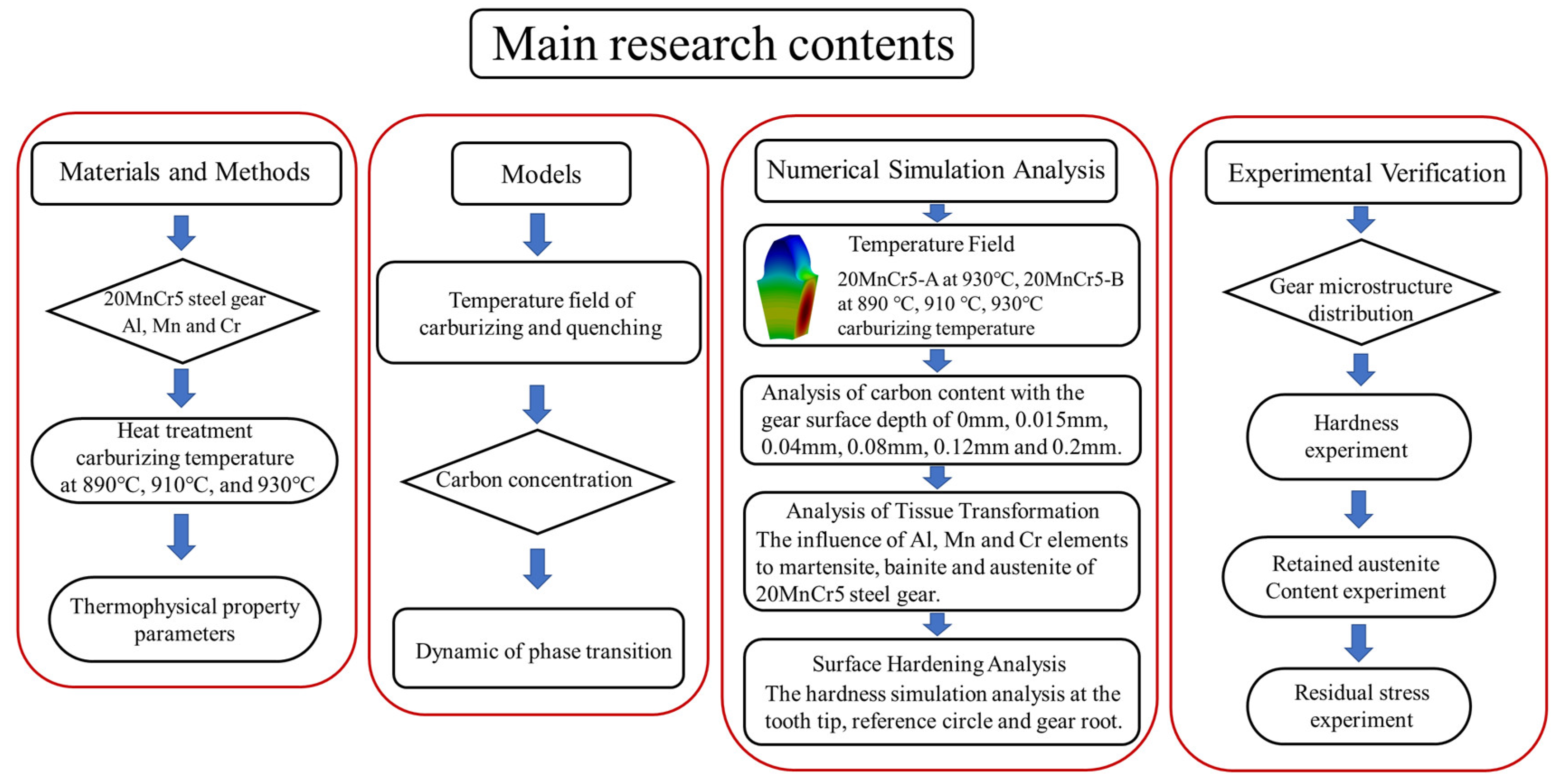
2. Materials and Methods
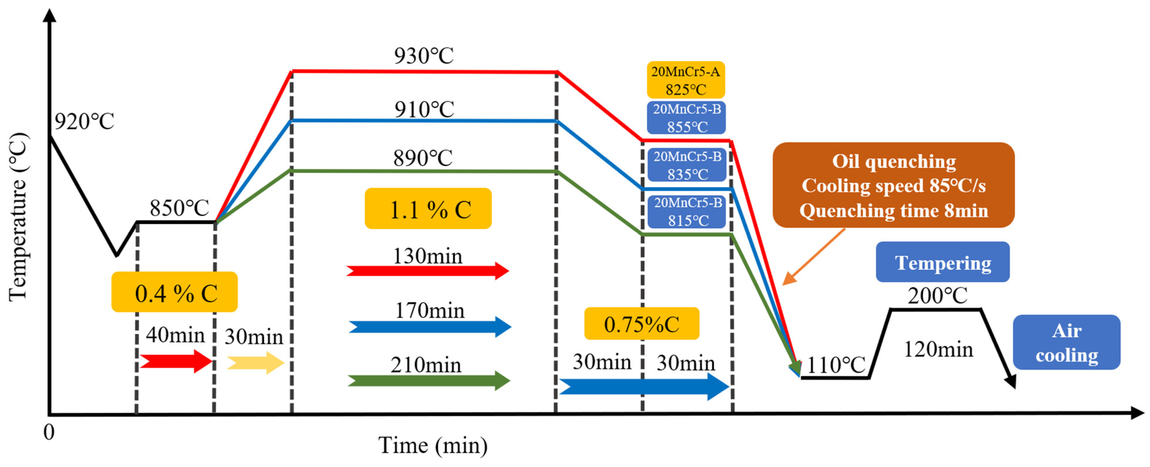
20MnCr5 low-carbon alloy steel can be used as the material for transmission gears of new energy vehicles. This paper studies the influence of the alloying element ratio and heat treatment parameters of 20MnCr5 steel gears on the volume of martensite and retained austenite, and the hardness and residual stress at different depths, which can serve as a guide to manufacturing and strengthening process of 20MnCr5 steel gears.

2.1. Heat Treatment

The gears were heated in the carburizing furnace for 30 min to reach the carburizing temperatures of 890 °C, 910 °C and 930 °C, and then diffused under 1.1% carbon potential for 210 min, 170 min and 130 min, respectively. The gear carburizing temperature is reduced by 75 °C, and is kept at 0.75% carbon potential for 30 min. The carburizing atmosphere is obtained using an RX atmosphere (Beijing Aichelin Heat Treatment Systems Co., Ltd., Beijing, China). Then the gear is quenched and quickly cooled to 110 °C in the KR488 quenching oil (Nanjing Kerun Lubricants Co., Ltd., Nanjing, China) at the temperature of 80 °C, the oil quenching rate is 85 °C/s and the quenching agitator speed is 750 rpm for 8 min. Finally, it is tempered at 200 °C for 120 min and cooled in the air. The surface carburizing diffusion process is shown in Figure 2, and the numerical simulation and gear heat treatment process is shown in Figure 3.

2.2. Materials

2.2.1. Chemical Composition of Materials

In this paper, Table 1 shows the chemical composition of two kinds of 20MnCr5 steel with different proportions of Al, Mn and Cr elements.

2.2.2. Material Phase Change Parameters

The CCT curves of 20MnCr5-A and 20MnCr5-B steel are shown in Figure 4. Letters A, B, F, P and M are austenite, bainite, ferrite, pearlite and martensite. The colored lines are the temperature boundaries where austenite, bainite, ferrite, pearlite and martensite transform into each other. The black solid lines are the boundaries of the phase transformation products of the metallographic structure at different cooling rates. 20MnCr5-A steel has the austenite phase transition temperature Ac1 of 728.3 °C, Ac3 of 769.4 °C, pearlite formation temperature of 527~724 °C, bainite formation temperature of 440~585 °C and martensite formation temperature of 276.1~388.1 °C, while 20MnCr5-B steel has the austenite phase transition temperature Ac1 of 729.7 °C, Ac3 of 802.2 °C, pearlite formation temperature of 493~717 °C, bainite formation temperature of 466~590 °C and martensite formation temperature of 286.1~397.2 °C. By regulating the proportion of Al element in 20MnCr5 steel, the austenitic phase region is reduced and the temperature of Ac3 is increased. When the cooling rate is 30~100 °C/s, a large amount of martensite and bainite, and a small amount of ferrite and retained austenite, are formed.

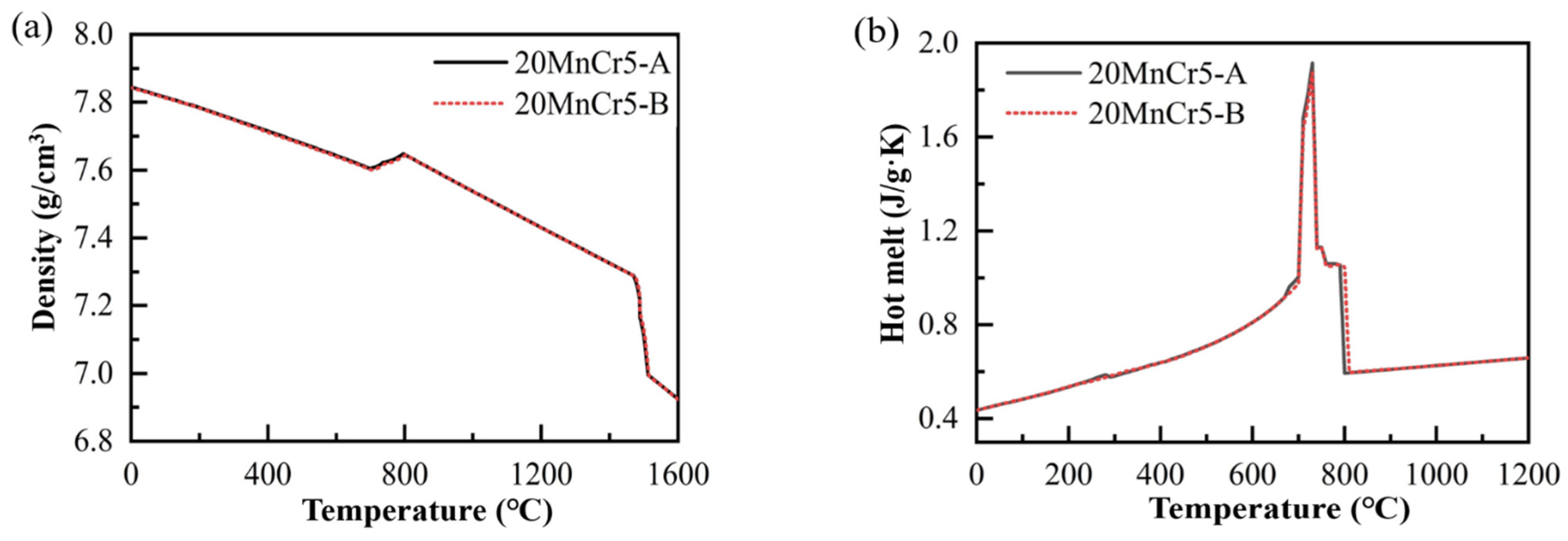
2.2.3. Thermophysical Property Parameters

The thermophysical property parameters of 20MnCr5-A and 20MnCr5-B steel gears are almost consistent. The performance parameters are affected by the chemical composition of the substrate, austenite grain size, quenching cooling rate and other factors, in which the chemical composition of the substrate is the most important factor [36,37,38]. The variation curves of density and hot melt parameters with temperature are shown in Figure 5. It can be seen from Figure 5a that when the material temperature is 0~680 °C, the material densities of both 20MnCr5-A and 20MnCr5-B steel are 7.60~7.84 g/cm³. With the increase in temperature, the material density decreases slowly, has a slight upward trend at 680 °C and then continues to decline. At 930 °C, the material density is 7.58 g/cm³. It can be seen from Figure 5b that when the material temperature is 0~700 °C, the hot melt volume of 20MnCr5-A and 20MnCr5-B steel rises slowly, rises rapidly at 700~720 °C, with a peak of 1.92 J/(g·K), then rapidly declines, and tends to be stable at 800~1200 °C.

3. Models

3.1. Temperature Field of Carburizing and Quenching

During the heat treatment, the temperature of the gear is raised by the heating furnace, and then the temperature of the gear is reduced by the process of heat preservation and rapid cooling. The heat transfer equation adopted is as follows:
ρ c T ˙ + T ε i j e T σ ˙ i j σ i j ε ˙ i j i ρ H ε i j i ε ˙ i j i ρ H K k ˙ + ρ I = 1 N l I ξ I = k 2 T x i 2
where ρ is the density of the mixed phase; c is the hot melt of mixed phase; T is the temperature; σ is the stress; ε is the elastic strain; H is the enthalpy change density; l is the latent heat; ξ is the phase variable; k is the thermal conductivity; x is the location.
Before carburizing and quenching, the temperature of each position of the gear is the same, and the conditions are determined as follows:
T | t = 0 = T 0
where T 0 is the initial temperature.
Simulating the temperature field of the gear during carburizing and quenching more accurately, appropriate heat conduction boundary conditions need to be set, which are the basis for the coefficient of heat transfer between the gear and the contact medium and the temperature of the medium [39]:
k T x i n i = h T T T M
where n i is the boundary of the gear, h T is the coefficient of heat transfer, T M is the external environment temperature.

3.2. Carbon Concentration

Fick’s second law is used to calculate the carbon diffusion. The carbon transfer coefficient and diffusion coefficient are determined. The governing equation is as follows:
C t x i D c C x i = 0
where C is the content of carbon, t is the time of carburizing, x i is the carburizing position, D c is the coefficient of carbon diffusion.
The coefficient of carbon diffusion is affected by the carburizing temperature and the content of alloy [40]. The formula is as follows:
D c = 0.47 p · exp 1.6 C · exp 37000 6600 C R c T
where R c is the gas phase and its value is 1.986 cal/mol/K, p is the alloy influence factor.
The type and content of elements in the material have great influence on the carburizing process:
p = 1 + 0.15 + 0.033 S i S i 0.0365 M n 0.13 5.5 e 3 C r C r + 0.03 0.03365 N i N i 0.025 0.01 M o M o 0.03 0.02 A l A l ( 0.016 + 1.4 e 3 C u ) C u ( 0.22 0.01 V ) V
where S i , M n , C r , A l etc. are the gear steel element mass fraction.
Determine the uniformly distributed carbon concentration of steel:
C | t = 0 = C 0
where C 0 is the gear steel initial carbon content.
The rate of carbon potential diffusion from the gear surface to the core is proportional to the difference between the external carbon potential atmosphere and the gear carbon mass fraction:
D C C x i = β C ( C C w )
where C w is the external carbon potential atmosphere; x i is the location; β C is the carbon atom transfer coefficient.
Considering the temperature of carburizing, other values of carbon transfer coefficient are taken as constants:
β C = β 0 e x p ( E f T a R )
where β C is the transfer coefficient, and the value is 1.1587 × 10⁻⁴ mm/s; β 0 is material property, and the value is 3.47 × 10⁻³ mm/s; E f is the activation energy, and the value is 34 kJ/mol; T a is the temperature of carburizing; R is the molar gas, and the value is 8.314 J/(mol·K).

3.3. Dynamic of Phase Transition

In this paper, the Inoue model was adopted [41]. The volume fraction of the diffusive phase transition was calculated:
ξ B P = 1 exp 0 t f 1 T f 2 σ i j f 3 C t τ 3 d τ
where ξ B / P is the volume fraction; T is the temperature; σ i j is the stress; C is the carbon content.
In the non-diffused phase transition, the diffusion ability of atoms is weakened or even lost due to the low transition temperature. The whole transformation process is not controlled by time. The volume fraction of non-diffused phase transition was calculated:
ξ M = 1 e x p ( δ 1 T + δ 2 ( C C 0 ) + δ 3 σ m + δ 4 σ e + δ 5 )
where ξ M is the martensite volume; σ m is the average stress; σ e is the equivalent stress; δ 1 , δ 2 , δ 3 , δ 4 and δ 5 are the test coefficients.

4. Numerical Simulation Analysis

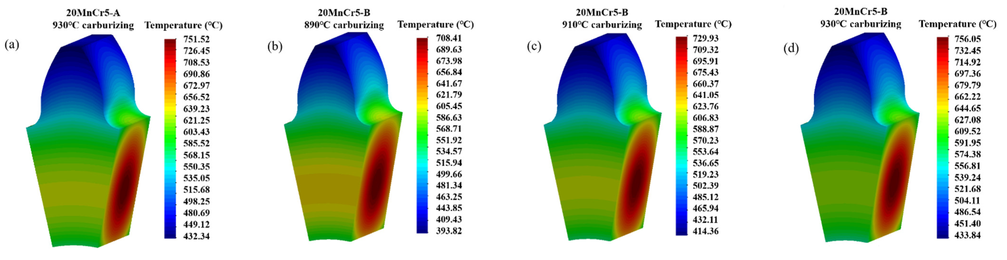
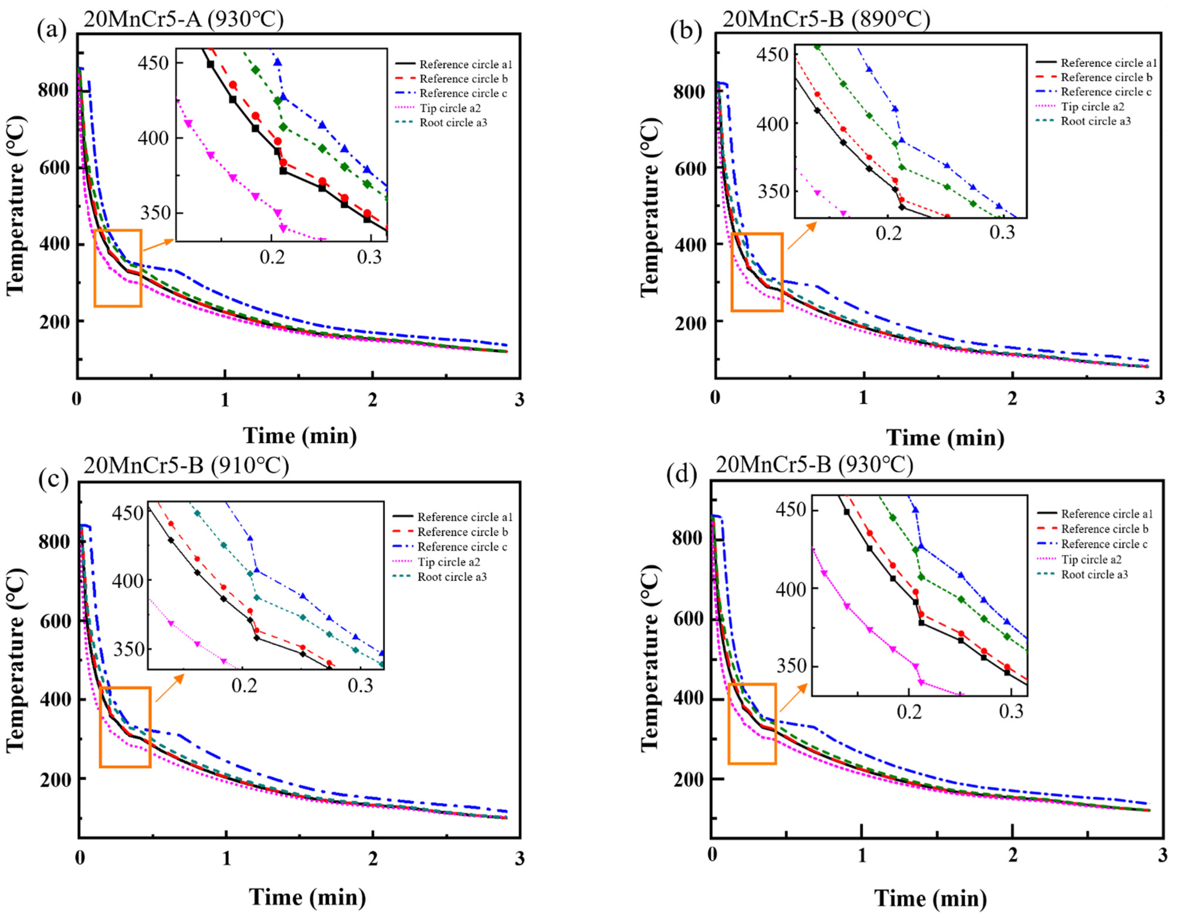
4.1. Temperature Field

The gear used in this paper is an involute gear of type FZG-C. Hobbing is employed to process the gear using a hobbing cutter, and the hobbing machine model is Y3150E. After the heat treatment processes at 890 °C, 910 °C and 930 °C carburizing, as well as the low-temperature tempering at 200 °C described in Section 2.1, the gear undergoes profile grinding. The grinding depth is 200 μm, and the grinding machine model is KN-G320A. The parameters of the gear are shown in Table 2. To analyze the dynamic change of temperature of the 20MnCr5-A and 20MnCr5-B steel gears during heat treatment, a single tooth of the gear is divided along the middle plane of the tooth width direction. Numerical simulation meshing was carried out for individual teeth. Test points are taken at the tooth tip, reference circle and gear root, respectively, at the split position. Meanwhile, three test points are taken outside-in along the reference circle for analysis. The locations of all the points are shown in Figure 6: a1, b and c are the test points from the surface depth of 0 mm, 1.25 mm and 3 mm to the core at the gear reference circle, and a2 and a3 are the surface depth of 0 mm at the tooth tip and the gear root.
The temperature field simulation of gear quenching process is shown in Figure 7a–d. According to Equations (1)–(3) in Section 3.1, after carburizing of the 20MnCr5-A steel gear at 930 °C and of the 20MnCr5-B steel gear at 890 °C, 910 °C and 930 °C, and quenching for 5 s, the difference of temperature between the gear surface and the core is 319.18 °C, 314.59 °C, 315.57 °C and 322.21 °C, respectively. The higher temperature of carburizing at the early quenching stage have a greater impact on the temperature difference of the gear, and the faster quenching cooling rate can promote the formation of more martensite [42]. The gear surface and core quenching temperature of the 20MnCr5-A steel gear is slightly lower than that of the 20MnCr5-B steel gear, when carburizing at 930 °C, which indicates that the increase in Al content to 0.032% helps the 20MnCr5 steel gear to reach the carburizing temperature quickly.
The temperature field variation curve of the gear quenching process is shown in Figure 8a–d. The quenching temperature of the 20MnCr5-A steel gear at 930 °C and of the 20MnCr5-B steel gear at 890 °C, 910 °C and 930 °C rises successfully at points a1, b and c. This is because in the quenching process, the closer the distance to the gear surface, the faster the quenching cooling rate. When the 20MnCr5-B steel gear is carburized at 890 °C, 910 °C and 930 °C, the temperature variation at 0~0.5 min is greatly affected by the initial quenching temperature, and the temperature variation trend is consistent at points a1–3, b and c. The 20MnCr5-A and 20MnCr5-B steel gears have a similar trend of quenching temperature change at points a1–3, b and c during carburizing at 930 °C, indicating that by changing the proportion of Al, Mn and Cr elements, the influence on temperature change during quenching is small. At the quenching time of 0~0.2 min, the whole gear cooling rate is high, and the temperature of each phase transition point is reached first, generating latent heat of phase transition, transferring a small amount of heat to the gear core, and further delaying the cooling rate of the core. After quenching for 0.2 min, the quenching rate of the gear decreases gradually. The difference in the gear surface and core temperature increases rapidly and then decreases slowly, and finally, the temperature of the whole gear tends to be consistent.

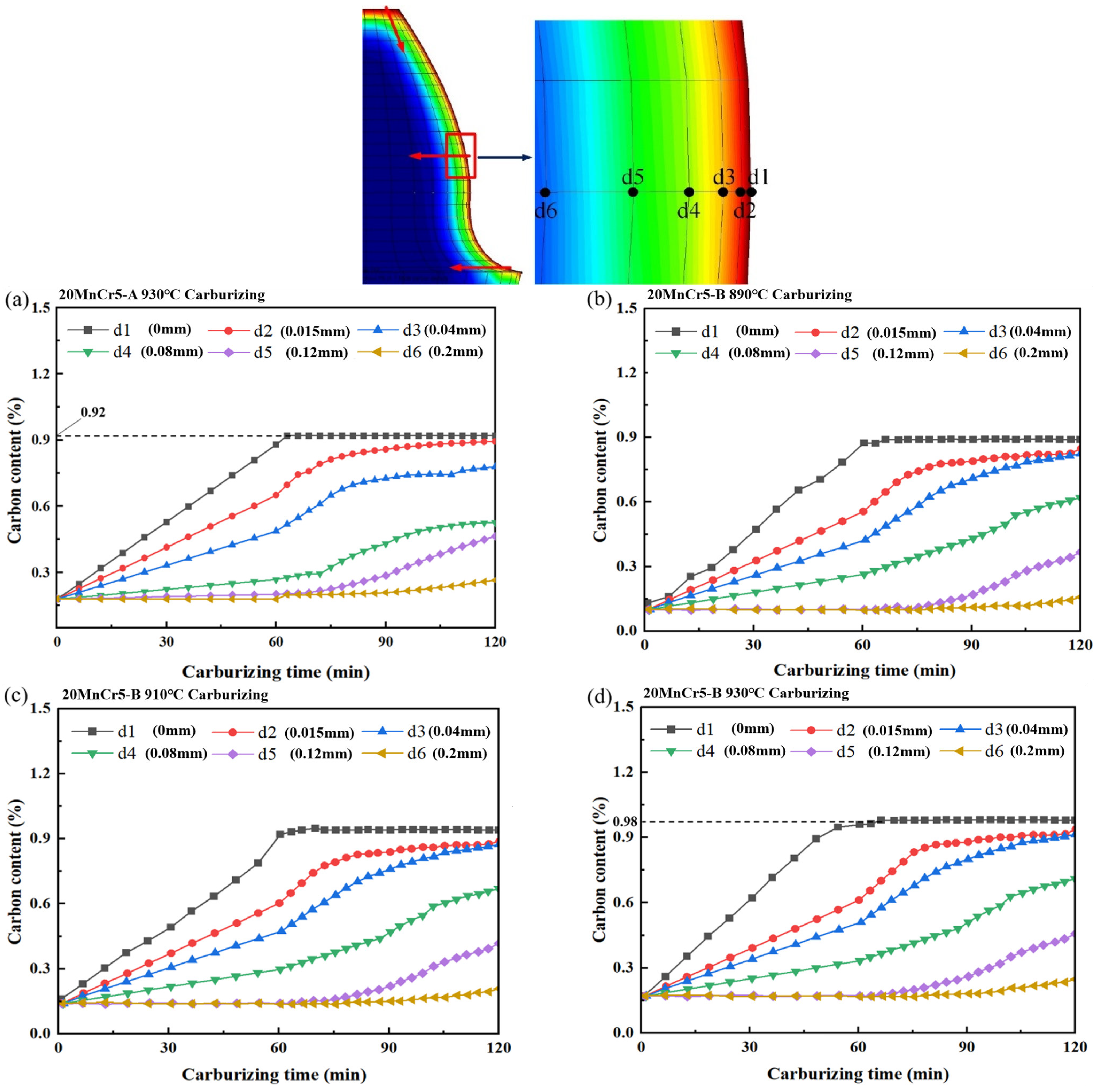
4.2. Analysis of Carbon Content

The carbon content changes at points d1, d2, d3, d4, d5 and d6, with the gear surface depth of 0 mm, 0.015 mm, 0.04 mm, 0.08 mm, 0.12 mm and 0.2 mm, are analyzed. The carbon content at different depths of the gear after heat treatment is shown in Figure 9. According to Equations (4)–(6) in Section 3.2, during the 20MnCr5-A steel gear carburizing at 930 °C and 20MnCr5-B steel gear at 890 °C, 910 °C and 930 °C, the carbon content at the d1~d4 points on the gear surface shows a linear increase trend during 0~60 min carburizing, while the carbon content at points d5 and d6 do not change significantly. During 60~120 min carburizing, the carbon content at points d1~d4 on the gear surface reaches the peak and does not increase. The carbon content at points d5 and d6 begin to gradually increase, indicating that the farther the distance from the gear surface, the more difficult the carbon potential to reach and diffuse. Compared with 890 °C and 910 °C, the carbon content at 930 °C is higher at the same depth. After carburizing at 930 °C, the 20MnCr5-A and 20MnCr5-B steel gear surfaces have the 0.92% and 0.98% carbon content, indicating that the increase in Al content to 0.032% is conducive to the carbon potential diffusion. From point d1 to d6, with the gear carburizing depth increasing, the peak carbon content decreases successively, the lag time of carbon transfer from the gear surface to core gradually prolongs, and the peak carbon content decreases continuously. Point d6 is almost unaffected by the external carbon potential. When carbon atoms diffuse to the inside of the gear, a large number of carbon atoms will be absorbed by the gear surface, and only a small number of carbon atoms continue to diffuse to the gear core. Therefore, the closer to the gear core, the smaller the change in carbon content and the smaller the transfer rate of carbon.
The depth of carburized layer after carburizing and quenching of tooth tip, reference circle and gear root is analyzed, and the carbon content distribution curve is shown in Figure 10. In this paper, the depth of the carburized layer is defined by 0.35% carbon content from the gear surface. According to Equations (7)–(9) in Section 3.2, the carburized layer depth of the 20MnCr5-A steel gear at the reference circle after carburizing heat treatment at 930 °C is 0.87 mm. The carburized layer depth of the 20MnCr5-B steel gear at the reference circle after carburizing heat treatment at 890 °C, 910 °C and 930 °C is 0.72 mm, 0.91 mm and 0.98 mm, indicating that the increase in carburizing temperature is beneficial for carbon atoms to penetrate deeper into gear surface. Compared with the 20MnCr5-A steel gear, the 20MnCr5-B steel gear surface has a significantly increased carburized layer depth after carburizing at 930 °C. 20MnCr5-B steel contains more Mn, Cr and Al elements, indicating that increasing the proportion of these elements in 20MnCr5 steel will facilitate the carbon atoms to combine with the steel substrate during carburizing, resulting in a higher carbon content at the same depth. From Figure 10, when the carbon mass fraction is more than 0.35%, there are high carbon potential sources in multiple directions during the process of carbon potential diffusion to the gear core due to the horn effect of the tooth tip. Therefore, the carburized layer at the tooth tip is deeper.

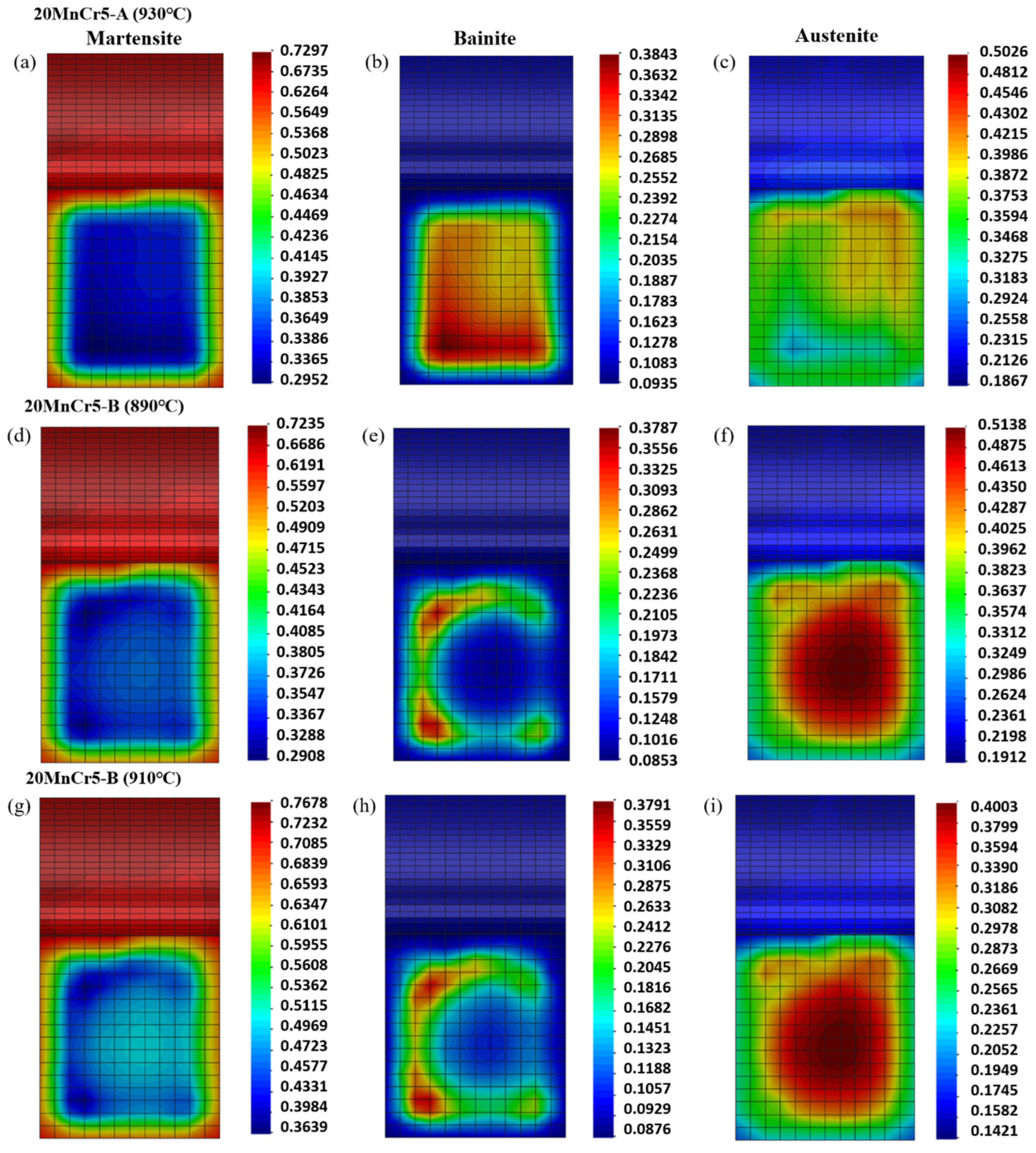
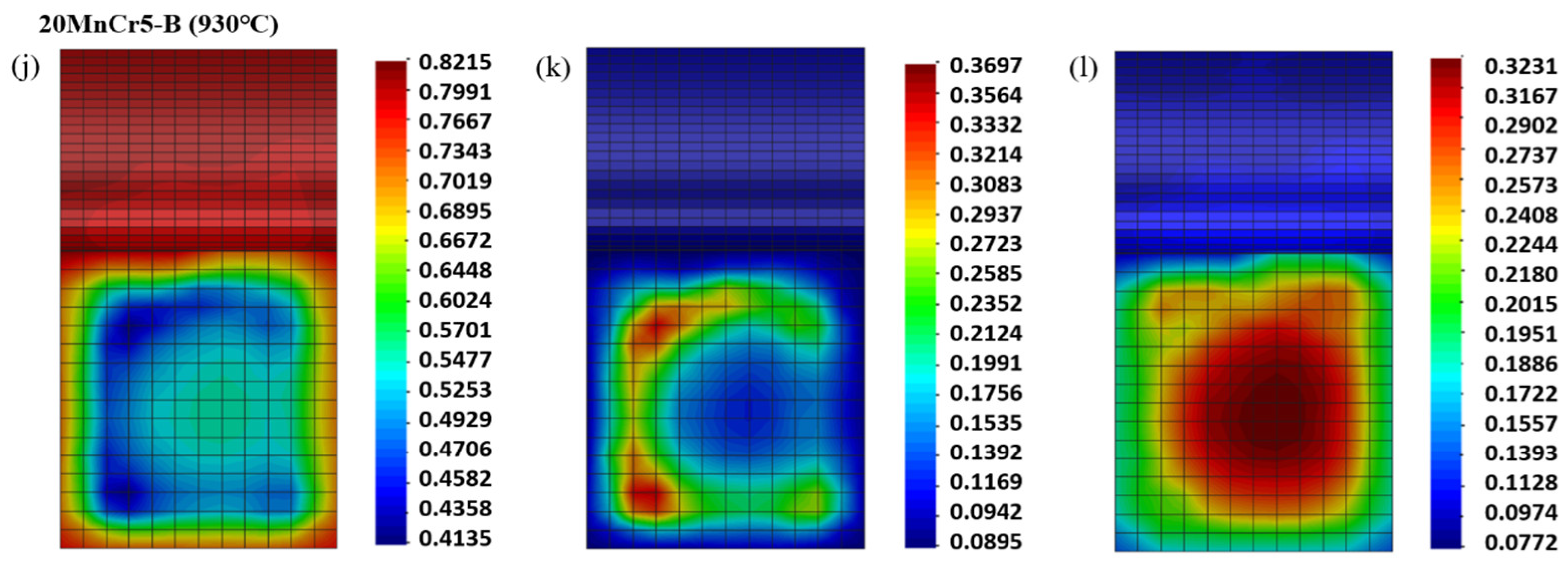
4.3. Analysis of Tissue Transformation

Figure 11 shows the distribution of martensite, bainite and austenite of the 20MnCr5 steel gear after heat treatment. From Figure 11a,d,g,j, according to Equations (10) and (11) in Section 3.3, more martensitic structures are generated on the gear surface after quenching, and the martensitic volume gradually decreases from the gear surface to the gear core. As shown in Figure 11, compared with the 20MnCr5-A steel gear after carburizing at 930 °C, the 20MnCr5-B steel gear has the martensite content on the surface and in the core increased from 72.97% and 29.52% to 82.15% and 41.35%, respectively, and the austenite content on the surface and in the core decreased from 18.67% and 50.26% to 7.72% and 32.31%, respectively, after carburizing at 930 °C. It indicates that increasing the content of Al to 0.032% is beneficial to greatly reduce the retained austenite volume. From Figure 11d–l, with the carburizing temperature increasing, the martensite volume on the 20MnCr5-B steel gear surface also increases, while the volume of retained austenite gradually decreases. The 20MnCr5-B steel gear has the largest martensite volume fraction at 930 °C, 82.15% at the tooth tip, 79.91% at the reference circle and 76.67% at the gear root. This is because the temperature at the tooth tip drops faster than that at the tooth surface and root during quenching. Due to the high carbon content on the gear surface, the initial temperature of martensitic transformation decreases after quenching, resulting in the retained austenite. The bainite is less affected by carburizing temperature, but its microstructure changes with the carburizing temperature and Al content. And more Mn and Cr elements will reduce the driving force of bainite nucleation.

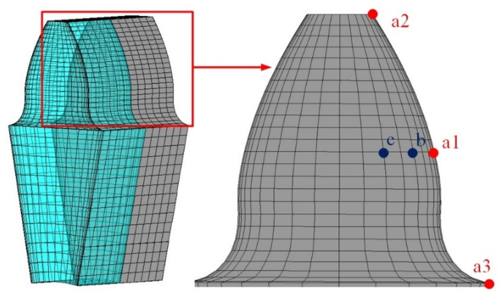
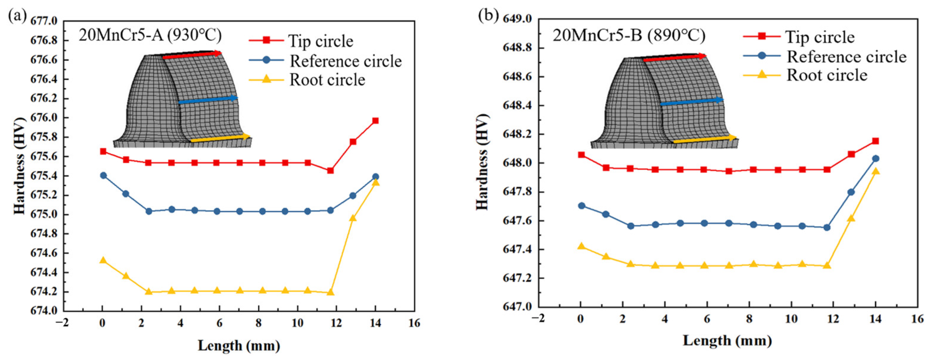
4.4. Surface Hardening Analysis

The hardness simulation results at the tooth tip, reference circle and gear root are shown in Figure 12. The tooth tip more easily reaches the carburizing temperature, and the quenching temperature is reduced faster. As a result, more carbon atoms will penetrate into the tooth tip, and the carburized layer at the tooth tip is deeper. The faster quenching cooling rate will promote more austenite to transform to martensite, so the tooth tip is harder. The farther the tooth tip, reference circle and root are from the gear face, the lower the hardness. Due to the high carbon potential sources in multiple directions, the closer to the gear face, the harder it is. The surface hardness of the 20MnCr5-A and 20MnCr5-B steel gears decreases gradually along the direction of the tooth tip, reference circle and gear root. When the 20MnCr5-A steel gear is carburized at 930 °C, the tooth surface is in the hardness range of 674.20~676.03 HV. When the 20MnCr5-B steel gear is carburized at 890 °C, 910 °C and 930 °C, the tooth surface is in the hardness range of 647.28~648.17 HV, 651.26~652.18 HV and 683.27~684.15 HV, and the hardness is mainly related to the martensite volume on the gear surface and the carbon content in the structure [43]. The hardness of the 20MnCr5-B steel gear changes little, showing the high consistency, and indicating that the increase in Al content to 0.032% can improve the uniformity of the surface of carburized and quenched 20MnCr5 steel.

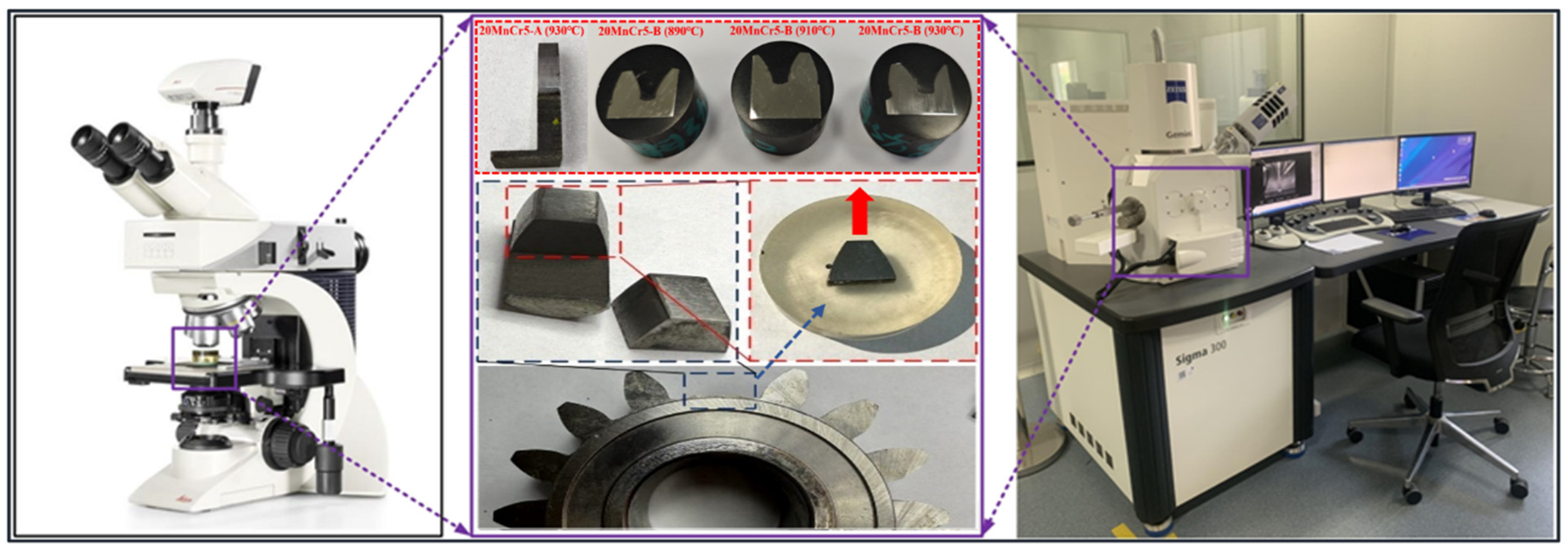
5. Experimental Verification

From Figure 13, the scanning electron microscope (SEM) is used to analyze the carburizing diffusion, martensite and retained austenite, and the microtopography of the gear.

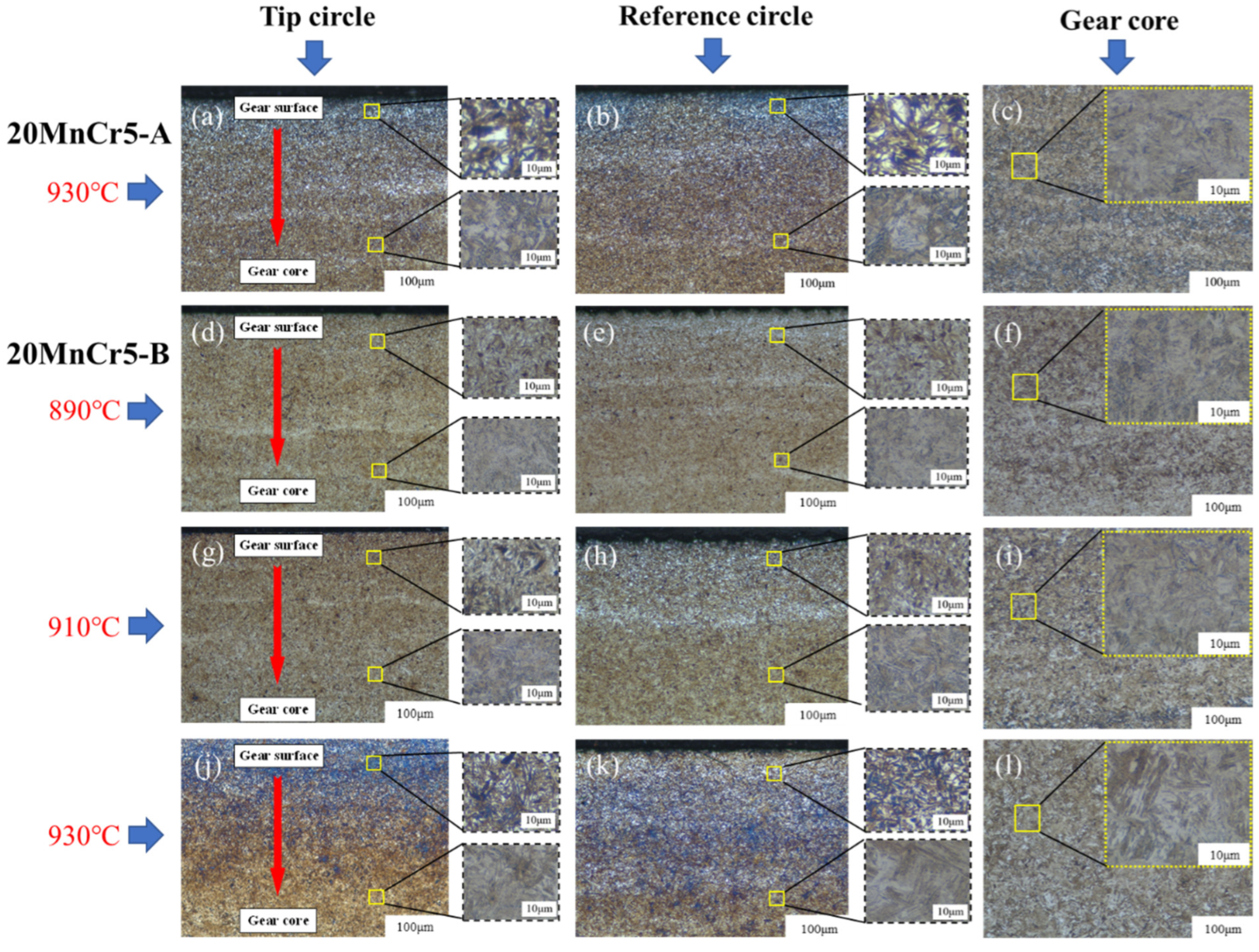
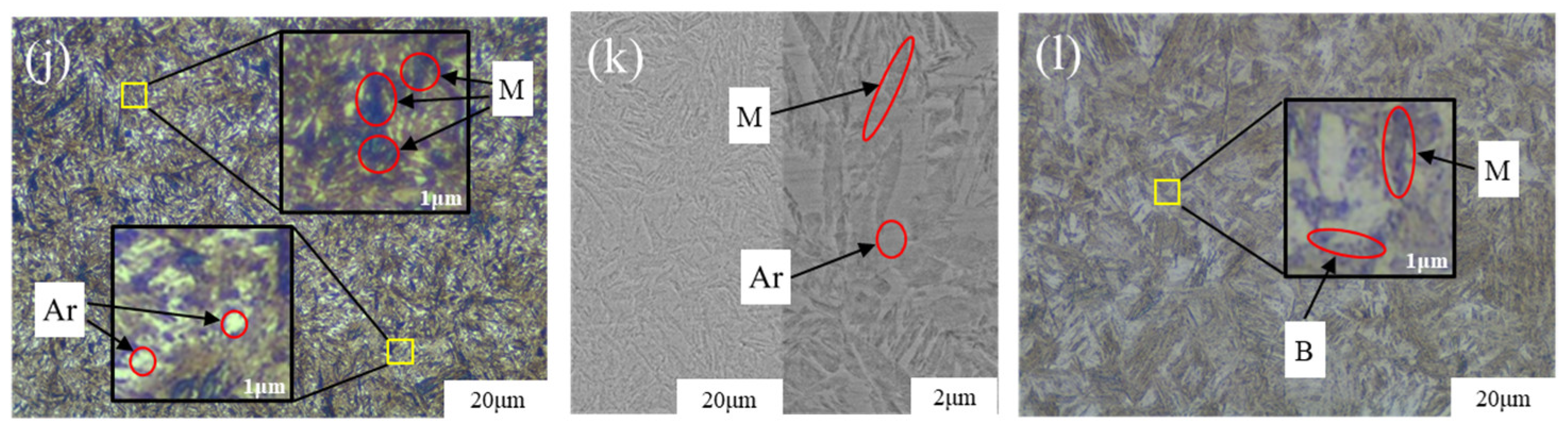
5.1. Gear Microstructure

The gear sample was etched with Nital solution for 15 s. Figure 14 and Figure 15 show that the microstructure distribution of the surface and core of the 20MnCr5-A steel gear after carburizing at 930 °C and of the 20MnCr5-B steel gear after carburizing at 890 °C, 910 °C and 930 °C.
Figure 14a–l show the tooth tip, reference circle and gear core microstructure at the microscale of 100 µm and 10 µm. From Figure 14a–c, the 20MnCr5-A steel gear shows traces of carbon potential diffusion from the surface to the gear core of the gear at the microscale of 100 μm after carburizing at 930 °C. At the microscale of 10 μm, there are more acicular and massive martensite and massive retained austenite on the gear tooth tip and reference circle. At the gear core, there are mainly a mixture of martensite, bainite and austenite, and massive retained austenite.
Figure 14d–l show that carburizing at 890 °C, 910 °C and 930 °C, the 20MnCr5-B steel gear has the carbon potential diffused from the gear surface to the core. When carburizing at 930 °C, the carbon potential diffuses evenly to the core, and the carbon potential diffusion effect is better. When carburizing at 930 °C, the carbon potential diffuses more evenly at the reference circle, which is the key position of gear meshing. The uniform diffusion of carbon potential is conducive to improving the anti-fatigue performance of gear meshing position. Compared to carburizing at 890 °C and 910 °C, the 20MnCr5-B steel gear, after carburizing at 930 °C, carbon potential diffusion for 130 min and low tempering at 200 °C, has more fine martensitic structures on the tooth tip and the reference circle, and significantly reduced retained austenitic structures, and the grain size of metallographic structure is unchanged. More fine-grained martensite structure and less retained austenitic structure will improve the hardness. The microstructure of the 20MnCr5-B steel gear core after carburizing at 890 °C, 910 °C and 930 °C is mainly a finer mixture of martensite, bainite and austenite, which has better chemical and mechanical stability.
The 20MnCr5-B steel gear shows superior surface microstructure properties than the 20MnCr5-A steel gear after heat treatment at various carburizing temperatures. The change rate of the gear core temperature is much less than that of the gear surface, and the carbon potential of carburizing is difficult to reach the position of the gear core, so the gear core hardness is similar under different heat treatment processes. After measurement, the hardness of the 20MnCr5-A steel gear core is 419 HV, and that of the 20MnCr5-B steel gear core is 416 HV, 419 HV and 418 HV.
Figure 15 shows the microstructure of the gear surface and gear core at the microscale of 20 μm and 2 μm. Figure 15a,b show that after carburizing at 930 °C for 130 min and tempering at 200 °C for 120 min, there are more massive martensite and retained austenite on the 20MnCr5-A steel gear surface. From Figure 15d,g,j, with the carburizing temperature increasing, the carbon potential on the 20MnCr5-B steel gear surface continues to diffuse, and the martensitic structure becomes finer and more evenly distributed. Under the condition of carburizing at 930 °C, there are much fine acicular martensite (M) and a small amount of retained austenite (Ar) on 20MnCr5-B steel gear surface. Compared with the 20MnCr5-A steel gear, the microstructure and properties are significantly improved.
Figure 15b,e,h,k show that the retained austenite volume decreases, and the volume tends to decrease at the microscale of 20 μm and 2 μm, with the carburizing temperature of the 20MnCr5-B steel gear increasing. Compared with the the 20MnCr5-A steel gear, the 20MnCr5-B steel gear obtains finer martensite and fine sheet bainite after carburizing at 930 °C for 130 min and tempering at 200 °C for 120 min. The bainite divides the retained austenite into thin films, resulting in less retained austenite and smaller grain size. This indicates that the increase in Al content to 0.032% can improve the surface microstructure properties of 20MnCr5 steel after higher temperature of carburizing heat treatment. As can be seen from Figure 15c,f,i,l, the carbon potential does not diffuse to the gear core, which is mainly composed of martensite and bainite with good toughness.
Therefore, under the conditions of higher carburizing temperature, shorter carbon potential diffusion time and lower tempering temperature, the 20MnCr5-B steel gear has finer surface microstructure, larger martensite volume, less retained austenite volume and smaller grain size than 20MnCr5-A steel gear, and more uniform microstructure. In terms of the gear surface and core microstructure, the experimental results of the retained austenite and martensite volume and the comparison with the numerical simulation analysis show a high consistency.

5.2. Hardness

Figure 16 shows the surface hardened layer depth at the position of the 20MnCr5 steel gear reference circle. The testing machine company name is Laizhou Huayin Testing Instrument Co., Ltd. (Laizhou, China), and the model number is HVS-1000ZL. The hardness test was carried out under HV1 load. The hardness of the 20MnCr5-A steel gear is 690 HV at the surface depth of 0 mm after carburizing at 930 °C. When the 20MnCr5-B steel gear is carburized at 890 °C, 910 °C and 930 °C, the hardness at the surface depth of 0 mm is 668 HV, 672 HV and 711 HV, respectively. By comparison with Figure 12, both simulation and experimental errors of the hardness of the gear surface are less than 4%. The 20MnCr5-A steel gear surface hardness after carburizing at 930 °C is second only to that of 20MnCr5-B steel gear carburizing temperature at the same. However, with the increasing depth towards the gear core, the hardness of the 20MnCr5-A steel gear decreases faster, and the hardness at the depth of 0.2~0.3 mm is gradually lower than that of the 20MnCr5-B steel gear at the same depth after carburizing at 890 °C and 910 °C. The 20MnCr5-A steel gear shows a higher hardness gradient and is more prone to fatigue crack initiation. Using 550 HV as the effective hardness value, the hardened layer depth of the 20MnCr5-A steel gear when carburizing at 930 °C is 0.72 mm, and that of the 20MnCr5-B steel gear when carburizing at 890 °C, 910 °C and 930 °C is 0.75 mm, 0.95 mm and 1.02 mm, respectively. At the same depth, the hardness of the 20MnCr5-B steel gear is higher when carburizing at 930 °C, indicating that increasing the proportion of the Al, Mn and Cr elements of the 20MnCr5 steel gear can effectively improve the gear surface hardness and obtain a more stable hardness gradient.

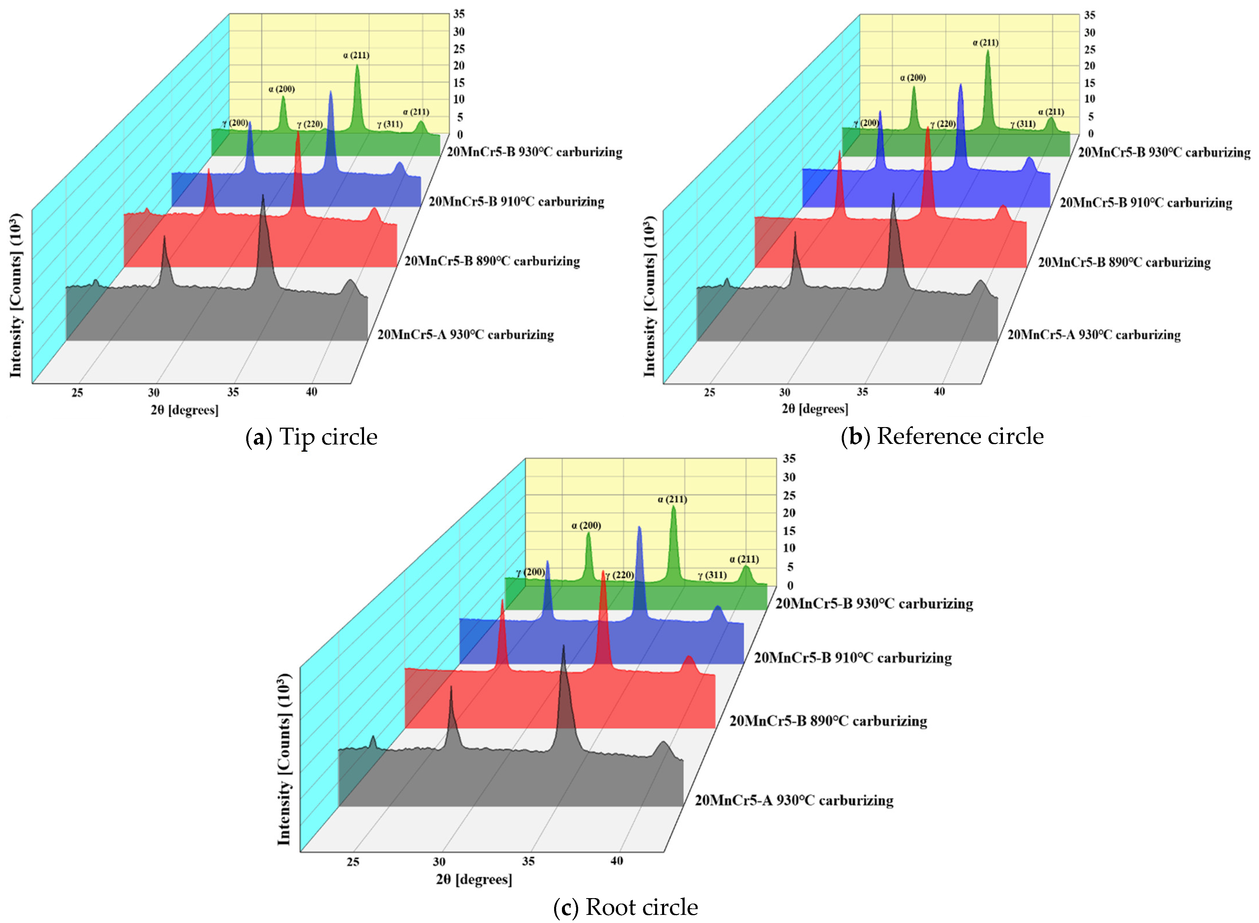
5.3. Retained Austenite

The retained austenite is measured by X-ray diffraction (XRD). During carburizing and quenching, the microstructure phase transition results in nucleation and dislocation accumulation. The nucleation extends to the periphery, resulting in the transformation of retained austenite to martensite and strengthening of the plastically deforming area.
The retained austenite at the tooth tip, reference circle and root of the 20MnCr5-A steel gear is shown in Figure 17. The martensite is composed of α (200) and α (211) crystal plane diffraction lines, and the retained austenite is composed of γ (200), γ (220) and γ (311) crystal plane diffraction lines. Scan 5 diffracted rays step by step to determine the corresponding diffraction angle 2θ. During the quenching, the temperature at the tooth tip drops faster, and the retained austenite content is less than that at the reference circle and root closer to the tooth core. As shown in Table 3, the volume of retained austenite of the 20MnCr5-A steel gear surface is 18.2~19.4% when carburized at 930 °C. The retained austenite volume on the 20MnCr5-B steel gear surface gradually decreases with the increase of temperature. At 890 °C, 910 °C and 930 °C, the retained austenite volume is 20.0~20.7%, 14.9~16.2% and 7.5~8.3%, respectively. By comparison with Figure 11, the actual measurement of the retained austenite volume at the tip circle, reference circle and root circle shows that the error with the numerical simulation is less than 5%. Increasing the Al, Mn and Cr elements can significantly reduce the austenite phase region and regulate the retained austenite.

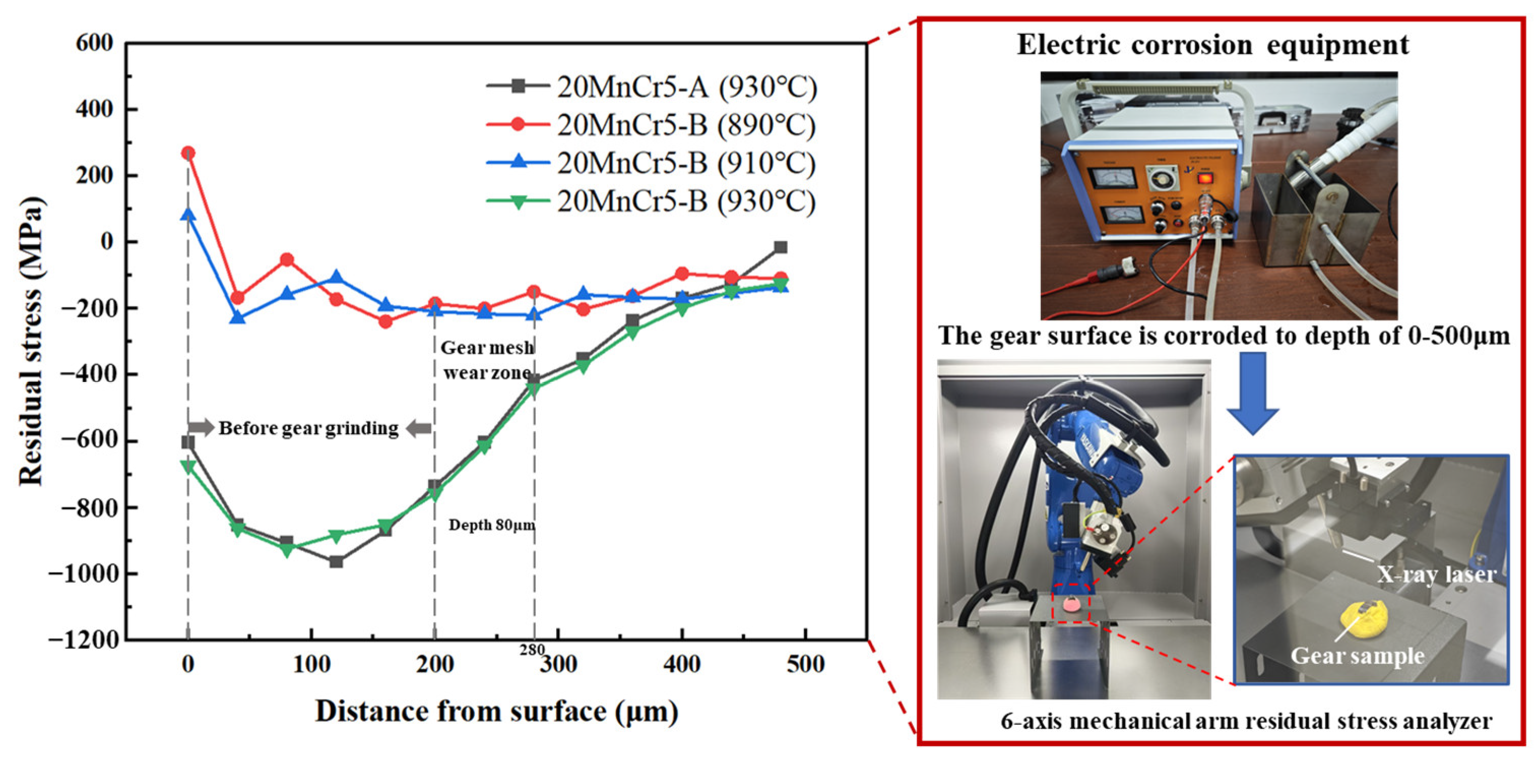
5.4. Residual Stress

The 20MnCr5 steel gear surface is electrochemically corroded by supersaturated sodium chloride solution. The residual stress analyzer of the 6-axis mechanical arm is used to test the residual stress at depths of 0~500 μm. The residual stress test results of the gear surface at different depths are shown in Figure 18.
The surface residual stress of the 20MnCr5-A and 20MnCr5-B steel gears increases first after carburizing at 930 °C, and gradually decreases and tends to be stable with the increasing depth. After carburizing at 890 °C and 910 °C, the surface residual stress of the 20MnCr5-B steel gear decreases first and then increases and tends to be stable, and the residual stress is small, which is not conducive to improving the fatigue life of the gear.
The gear needs to be ground 200 μm deep after heat treatment. Therefore, the residual stress of gear meshing wear depth at 200~280 μm depth is analyzed. The surface residual stress of the 20MnCr5-A and 20MnCr5-B steel gears increases after carburizing at 930 °C in the wear depth of the gear surface. After carburizing at 930 °C, the residual stress of the 20MnCr5-A and 20MnCr5-B steel gears at 200 μm depth reaches −735 MPa and −757 MPa, respectively, and at 280 μm depth, reaches −416 MPa and −441 MPa, respectively. After the Al element is increased to 0.032%, the residual stress of the gear surface is increased by 2.9~5.6%. The residual stress of the 20MnCr5-B steel gear after carburizing at 930 °C is increased by 200.4~362.2% compared with that at 890 °C and 910 °C.

6. Conclusions

This paper studied and analyzed the influence mechanism of temperature change, carbon content, carburized layer depth, gear surface hardness and austenite transformation of gear surface microstructure into martensite on two kinds of 20MnCr5 steel FZG gears with different Al, Mn and Cr content under an optimized carburizing heat treatment process; established a numerical simulation model of gear carburizing and quenching; tested and analyzed the metallographic structure, retained austenite and residual stress; and drew the following conclusions:
(1)
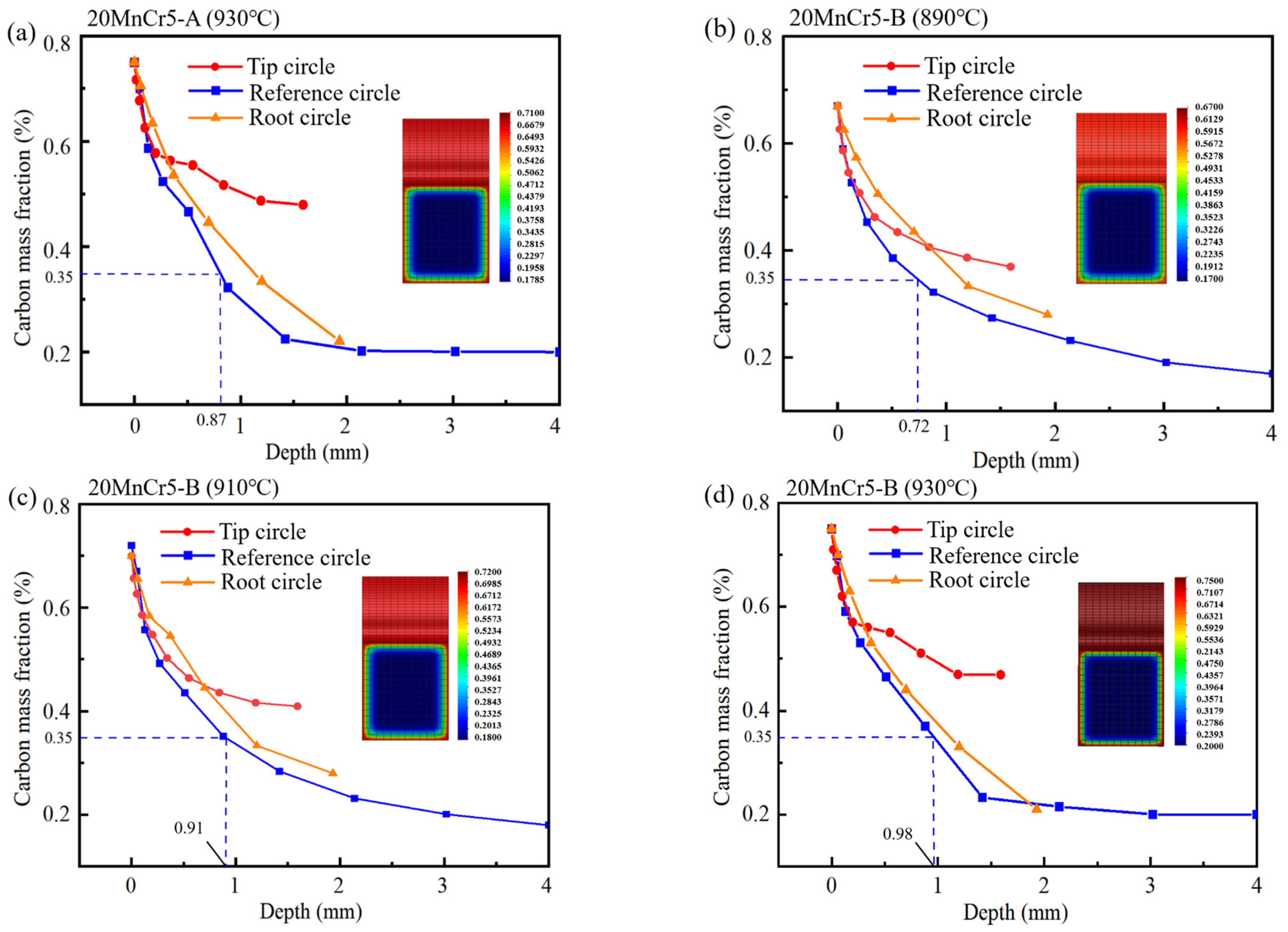
Regulating the content of Al, Mn and Cr elements makes the gear reach the carburizing temperature faster and improve the quenching rate. After carburizing heat treatment at 930 °C, the 20MnCr5-A and 20MnCr5-B steel gears have a carbon content on the gear surface of 0.92% and 0.98%, and have a carburized layer depth at the reference circle of 0.87 mm and 0.98 mm, respectively. The error between the simulated hardness and the test value is less than 4%.
(2)
Compared with the 20MnCr5-A steel gear, the 20MnCr5-B steel gear obtains finer martensite and fine sheet bainite after carburizing at 930 °C for 130 min and tempering at 200 °C for 120 min by increasing Al element to 0.032%. The bainite divides the retained austenite into thin films, greatly reducing the volume of retained austenite and grain size. The retained austenite volume at the tooth tip, reference circle and gear root is less than 8.3%. The error between the simulated retained austenite volume and the test value is less than 5%.
(3)
By regulating the content of Al, Mn and Cr elements, the residual stress is increased by 2.9~5.6% at the depth of gear meshing wear between 200 and 280 μm. After carburizing at 930 °C for 130 min and tempering at 200 °C for 120 min, the residual stress in the meshing wear zone of the 20MnCr5-B steel gear increases by 200.4~362.2% compared with carburizing at 890 °C and 910 °C.

Author Contributions

Conceptualization, L.L. and Y.C.; methodology, L.L. and Y.C.; software, L.L. and Z.J.; validation, F.Z., W.H., X.S. and Z.X.; formal analysis, L.L. and Z.J.; investigation, L.L. and Y.C.; resources, Y.C.; data curation, L.L. and Z.J.; writing—original draft preparation, L.L.; writing—review and editing, L.L.; visualization, L.L. and Y.C.; supervision, Y.C.; project administration, Y.C.; funding acquisition, Y.C. All authors have read and agreed to the published version of the manuscript.

Funding

The research was supported by Guangxi Science and Technology Major Program (Grant No. Guike AA23062029), and Guangxi Science and Technology Major Program (Grant No. Guike AA24263068).

Data Availability Statement

The original contributions presented in the study are included in the article, further inquiries can be directed to the authors.

Conflicts of Interest

Author Fucheng Zhao was employed by the company Ningbo Geely Royal Engine Components Co., Ltd. Author Weifeng Hua was employed by the company Changxing Geely Power Assembly Co., Ltd. The remaining authors declare that the research was conducted in the absence of any commercial or financial relationships that could be construed as a potential conflict of interest.

References

  1. Zaid, M.; Doquet, V.; Chiaruttini, V.; Depouhon, P.; Bonnand, V.; Pacou, D. On the influence of secondary branches on crack propagation in rolling contact fatigue. Int. J. Fatigue 2024, 182, 108211. [Google Scholar] [CrossRef]
  2. Koester, R.; Binder, A. Performance analysis of HTS excited 5 MW medium-speed wind turbine generators with different stator feeding concepts. IEEE Trans. Appl. Supercond. 2024, 34, 1–6. [Google Scholar] [CrossRef]
  3. Wang, L.; Zhu, F.; Hao, N.; Cai, J.; Sun, W. Design optimization of external engagement cylindrical gear flowmeter under uncertainty. Struct. Multidiscip. Optim. 2024, 67, 63. [Google Scholar] [CrossRef]
  4. Tang, N.; Huang, X.; Huang, Y.; Tong, S.; Cong, F. Investigation of gear meshing vibration and meshing impact resonance intensity assessment. J. Comput. Nonlinear Dyn. 2024, 19, 051008. [Google Scholar] [CrossRef]
  5. Chen, Z.; Sha, H.; Li, S.; Tong, Z.; Tong, S. Stochastic uncertain lubrication in gear transmission subjected to tribodynamic loading. Friction 2024, 12, 1741–1756. [Google Scholar] [CrossRef]
  6. You, S.; Tang, J.; Wei, Z.; Zhou, W.; Zhao, J.; Chen, H. Research on calculation of contact fatigue life of rough tooth surface considering residual stress. Eng. Fail. Anal 2022, 140, 106459. [Google Scholar] [CrossRef]
  7. Zhang, B.; Liu, H.; Zhu, C.; Ge, Y. Simulation of the fatigue-wear coupling mechanism of an aviation gear. Friction 2021, 9, 1616–1634. [Google Scholar] [CrossRef]
  8. Zhang, B.; Liu, H.; Zhu, C.; Li, Z. Numerical simulation of competing mechanism between pitting and micro- pitting of a wind turbine gear considering surface roughness. Eng. Fail. Anal. 2019, 104, 1–12. [Google Scholar] [CrossRef]
  9. Zhang, N.; Guo, S.; He, G.; Jiang, B.; Zhou, L.; Chen, Y.; Liu, Y. Failure analysis of the carburized 20MnCr5 gear in fatigue working condition. Int. J. Fatigue 2022, 161, 106938. [Google Scholar] [CrossRef]
  10. Ding, H.; Zou, X.; Hua, S.; Zhou, Z.; Li, G.; Liu, H.; Tang, J. Carburizing effect-inspired bending fatigue forecasting model for spiral bevel gears. Int. J. Mech. Sci. 2023, 242, 107987. [Google Scholar] [CrossRef]
  11. Wang, W.; Liu, H.; Zhu, C.; Sun, Z. Evaluation of contact fatigue life of a wind turbine carburized gear considering gradients of mechanical properties. Int. J. Damage Mech. 2019, 28, 1170–1190. [Google Scholar] [CrossRef]
  12. Chen, W.; He, X.F.; Yu, W.C.; Shi, J.; Wang, M.Q.; Yao, K.F. Nano- and microhardness distribution in the carburized case of Nb-Microalloyed gear steel. J. Mater. Eng. Perform. 2020, 29, 4626–4630. [Google Scholar] [CrossRef]
  13. Wang, W.; Liu, H.; Zhu, C.; Bocher, P.; Liu, H.; Sun, Z. Evaluation of rolling contact fatigue of a carburized wind turbine gear considering the residual stress and hardness gradient. J. Tribol. 2018, 140, 061401. [Google Scholar] [CrossRef]
  14. Wang, W.; Liu, H.; Zhu, C.; Tang, J.; Jiang, C. Evaluation of contact fatigue risk of a carburized gear considering gradients of mechanical properties. Friction 2020, 8, 1039–1050. [Google Scholar] [CrossRef]
  15. Chen, W.; He, X.; Yu, W.; Shi, J.; Wang, M.; Yao, K. Rotating bending fatigue properties of case carburized steel with different fractions of retained austenite. J. Mater. Eng. Perform. 2022, 32, 7960–7968. [Google Scholar] [CrossRef]
  16. Gencoglu, S.; Yazici, A. Surface Characteristics and distortion analysis of the case-hardened helical gears: A comparison of different case-hardening treatments. Trans. Indian Inst. Met. 2020, 73, 119–126. [Google Scholar] [CrossRef]
  17. Cai, H.; Wang, Z.; Liu, L.; Li, Y.; Guo, F. Regulation mechanism of cooling rate and RE (Ce, Y, Gd) on Mg17Al12 in AZ91 alloy and it’s role in fracture process. J. Mater. Res. Technol. JMRT 2022, 19, 3930–3941. [Google Scholar] [CrossRef]
  18. Wang, Q.; Zhou, Y.; Deng, X.; Wang, Z. Achieving excellent mechanical properties and wear resistance in Fe49Mn30Co10Cr10C1 interstitial high-entropy alloy via tuning composition and stacking fault energy by Nb doping. Wear 2023, 534, 205149. [Google Scholar] [CrossRef]
  19. Tang, Y.; Li, D.Y. Influences of C, Si and Mn on the wear resistance of coiled tubing steel. Wear 2023, 524, 204854. [Google Scholar] [CrossRef]
  20. Liu, Z.; Niu, Z.; Liu, H.; Xu, K.; Qin, S. Simulation of residual stress of V-Notch specimen treated by ultrasonic rolling. J. Mater. Eng. Perform. 2024, 34, 1232–1242. [Google Scholar] [CrossRef]
  21. Wu, C.; Xu, W.; Wan, S.; Luo, C.; Lin, Z.; Jiang, X. Determination of heat transfer coefficient by inverse analyzing for selective laser melting (SLM) of AlSi10Mg. Crystals 2022, 12, 1309. [Google Scholar] [CrossRef]
  22. Iss, V.; Meis, J.; Rajaei, A.; Hallstedt, B.; Broeckmann, C. Fatigue strength evaluation of case-hardened components combining heat-treatment simulation and probabilistic approaches. Fatigue Fract. Eng. Mater. Struct. 2024, 47, 745–765. [Google Scholar] [CrossRef]
  23. Cheng, Q.; Zhang, J.; Conejo, A.N.N.; Liu, Z.; Wang, Y. Investigation of methane decomposition and carburization with iron: The combination of a ReaxFF molecular dynamics simulation and experimental work. J. Mater. Sci. 2023, 58, 9420–9433. [Google Scholar] [CrossRef]
  24. Izowski, B.; Wojtyczka, A.; Motyka, M. Numerical simulation of low-pressure carburizing and gas quenching for pyrowear 53 steel. Metals 2023, 13, 371. [Google Scholar] [CrossRef]
  25. Gong, S.; Su, L.; Wang, F. Nucleation and coarsening behavior of aluminum nitride and its effect on abnormal grain growth in high-temperature carburizing process. Met. Mater. Trans. A 2024, 55, 910–922. [Google Scholar] [CrossRef]
  26. An, X.; Tian, Y.; Wang, B.; Jia, T.; Wang, H.; Wang, Z. Prediction of the formation of carbide network on grain boundaries in carburizing of 18CrNiMo7-6 steel alloys. Surf. Coat. Tech. 2021, 421, 127348. [Google Scholar] [CrossRef]
  27. Liang, R.; Tian, G.; Gao, L.; Li, H. Optimization method for gear heat treatment process oriented to deformation and surface collaborative control. J. Mater. Eng. Perform. 2023, 33, 11376–11392. [Google Scholar] [CrossRef]
  28. Liu, H.; Zhao, J.; Tang, J.; Shao, W.; Sun, B. Simulation and experimental verification of die quenching deformation of aviation carburized face gear. Materials 2023, 16, 690. [Google Scholar] [CrossRef] [PubMed]
  29. Veronesi, P.; Balestri, A.; Colombini, E. Improvement in wear resistance of grade 37 titanium by microwave plasma oxy-carburizing. Technologies 2023, 11, 13. [Google Scholar] [CrossRef]
  30. Sondar, P.R.; Gurudath, B.; Ahirwar, V.; Hegde, S.R. Failure of hydraulic lathe chuck assembly. Eng. Fail. Anal 2022, 133, 106001. [Google Scholar] [CrossRef]
  31. Kanamori, H.; Ju, D. Identification of heat transfer coefficients and simulation of quenching distortions on disk probe. Mater. Trans. 2020, 61, 884–892. [Google Scholar] [CrossRef]
  32. Guo, J.; Deng, X.; Wang, H.; Zhou, L.; Xu, Y.; Ju, D. Modeling and simulation of vacuum low pressure carburizing process in gear steel. Coatings 2021, 11, 1003. [Google Scholar] [CrossRef]
  33. Li, X.; Ju, D.; Cao, J.; Ishikawa, K. Analysis of the distortion of the bearing rings after quenching. Coatings 2023, 13, 1190. [Google Scholar] [CrossRef]
  34. Deng, X.; Ju, D.; Li, M. Finite element modeling and experimental verification of nitriding process in S30C Steel. Mater. Res-Ibero-Am. J. 2017, 20, 509–513. [Google Scholar] [CrossRef]
  35. Liu, Q.; Jiang, J.; Chen, M.; Deng, X.; Wang, J.; Ju, D. Study on the mechanism of carbide precipitation by surface quenching treatment on GCr15 bearing rings based on the phase-field method. Front Mater. 2022, 9, 978025. [Google Scholar] [CrossRef]
  36. Biffi, C.A.; Fiocchi, J.; Tuissi, A. Selective laser melting of AlSi10 Mg: Influence of process parameters on Mg2Si precipitation and Si spheroidization. J. Alloy Compd. 2018, 755, 100–107. [Google Scholar] [CrossRef]
  37. Hussein, H.F.; Druga, L.; Cojocaru, M.; Dumitru, C.; Ghinea, A. The structural evolution of refractory steel spare parts during the successive carburizing. U Politeh. Buch. Ser. B 2020, 82, 247–257. [Google Scholar]
  38. Vasic, M.M.; Zak, T.; Minic, D.M. Kinetics and influence of thermally induced crystallization of Fe, Ni-containing phases on thermomagnetic properties of Fe40Ni40B12Si8 amorphous alloy. J. Therm. Anal. Calorim. 2022, 147, 3543–3551. [Google Scholar] [CrossRef]
  39. Zari, I.; Ali, F.; Khan, T.S.; Shafiq, A. Radiative Hiemenz flow towards a stretching Riga plate in hybrid nanofluid. Int. Commun. Heat Mass 2022, 139, 106492. [Google Scholar] [CrossRef]
  40. Wu, D.; Ge, Y.; Kahn, H.; Ernst, F.; Heuer, A.H. Diffusion profiles after nitrocarburizing austenitic stainless steel. Surf. Coat. Technol. 2015, 279, 180–185. [Google Scholar] [CrossRef]
  41. Ju, D.Y.; Zhang, W.M.; Zhang, Y. Modeling and experimental verification of martensitic transformation plastic behavior in carbon steel for quenching process. Mat. Sci. Eng. A-Struct. 2006, 438, 246–250. [Google Scholar] [CrossRef]
  42. Gao, Q.Z.; Di, X.J.; Liu, Y.C.; Yu, L.M.; Yan, Z.S. Athermal martensite transformation of modified high Cr ferritic heat resistant steel undergoing different quenching temperatures. Mater. Res. Innov. 2012, 16, 198–203. [Google Scholar] [CrossRef]
  43. Tian, Y.; Ju, J.; Fu, H.; Ma, S.; Lin, J.; Lei, Y. Effect of chromium content on microstructure, hardness, and wear resistance of as-Cast Fe-Cr-B alloy. J. Mater. Eng. Perform. 2019, 28, 6428–6437. [Google Scholar] [CrossRef]
Figure 1. Research process diagram.
Lubricants 13 00202 g001
Figure 2. Principle of the carburizing diffusion process of 20MnCr5 steel.
Lubricants 13 00202 g002
Figure 3. Carburizing–quenching process curve.
Lubricants 13 00202 g003
Figure 4. CCT curve of 20MnCr5 steel.
Lubricants 13 00202 g004
Figure 5. Curves of density and hot melt of 20MnCr5 steel with temperature; (a) variation curves of density with different temperature; (b) variation curves of hot melt parameters with different temperature.
Lubricants 13 00202 g005
Figure 6. Analytical position of the temperature dynamics of the quenching process.
Lubricants 13 00202 g006
Figure 7. Temperature field of gear when quenching for 5 s; (a) 20MnCr5-A steel gear carburizing at 930 °C and quenching for 5 s; (bd) 20MnCr5-B steel gear carburizing at 890 °C, 910 °C and 930 °C, and quenching for 5 s.
Lubricants 13 00202 g007
Figure 8. Temperature–time curves of quenching process of gears; (a) 20MnCr5-A steel gear carburizing at 930 °C and quenching; (bd) 20MnCr5-B steel gear carburizing at 890 °C, 910 °C and 930 °C, and quenching.
Lubricants 13 00202 g008
Figure 9. Carbon content–time curve at different positions of gears; (a) carbon content changes of 20MnCr5-A steel gear carburizing at 930 °C; (bd) carbon content changes of 20MnCr5-B steel gear carburizing at 890 °C, 910 °C and 930 °C.
Lubricants 13 00202 g009
Figure 10. Carbon content at different positions of gears; (a) the depth of 20MnCr5-A steel gear carburized layer after carburizing at 930 °C; (bd) the depth of 20MnCr5-B steel gear carburized layer after carburizing at 890 °C, 910 °C and 930 °C.
Lubricants 13 00202 g010
Figure 11. Distribution of martensite, bainite and austenite after carburizing and quenching of the gear; (ac) martensite, bainite and austenite of 20MnCr5-A steel gear after carburizing at 930 °C; (df) martensite, bainite and austenite of 20MnCr5-B steel gear after carburizing at 890 °C; (gi) martensite, bainite and austenite of 20MnCr5-B steel gear after carburizing at 910 °C; (jl) martensite, bainite and austenite of 20MnCr5-B steel gear after carburizing at 930 °C.
Lubricants 13 00202 g011aLubricants 13 00202 g011b
Figure 12. Surface hardness distribution after carburizing–quenching; (a) the surface hardness of 20MnCr5-A steel gear after carburizing at 930 °C; (bd) the surface hardness of 20MnCr5-B steel gear after carburizing at 890 °C, 910 °C and 930 °C.
Lubricants 13 00202 g012aLubricants 13 00202 g012b
Figure 13. Gear surface microstructure test.
Lubricants 13 00202 g013
Figure 14. Gear microscopic morphology; 20MnCr5-A steel gear: carburizing at 930 °C (ac); 20MnCr5-B steel gear: carburizing at 890 °C (df); carburizing at 910 °C (gi); carburizing at 930 °C (jl); (a,d,g,j) the tip circle surface; (b,e,h,k) the reference circle surface; (c,f,i,l) gear core.
Lubricants 13 00202 g014
Figure 15. Gear surface and core microscopic morphology; 20MnCr5-A steel gear: carburizing at 930 °C (ac); 20MnCr5-B steel gear: carburizing at 890 °C (df); carburizing at 910 °C (gi); carburizing at 930 °C (jl); (a,b,d,e,g,h,j,k) surface layer; and (c,f,i,l) gear core.
Lubricants 13 00202 g015aLubricants 13 00202 g015b
Figure 16. Test analysis of surface hardness and hardened layer depth at the 20MnCr5 steel gear reference circle.
Lubricants 13 00202 g016
Figure 17. Retained austenite on the gear surface.
Lubricants 13 00202 g017
Figure 18. Test of residual stress on gear surface.
Lubricants 13 00202 g018
Table 1. Chemical composition of two 20MnCr5 steel (wt %).
Type of SteelCSiMnPSCrNiMoCuAl
20MnCr5-A0.200.101.260.0120.0021.150.120.050.03
20MnCr5-B0.180.091.350.0120.0021.250.040.010.010.032
Table 2. FZG gear parameters.
ParameterDriving GearDriven Gear
Number of teeth1624
Coefficient of displacement0.1820.171
Tip circle diameter/mm82.5118.4
Module/mm4.5
Pressure angle/(°)20
Tooth width/mm14
Table 3. Retained austenite volume at different positions.
Retained Austenite VolumeTip Circle
(%)
Reference Circle
(%)
Root Circle
(%)
20MnCr5-A930 °C Carburizing18.218.919.4
20MnCr5-B890 °C Carburizing20.020.420.7
910 °C Carburizing14.916.016.2
930 °C Carburizing7.58.18.3
Disclaimer/Publisher’s Note: The statements, opinions and data contained in all publications are solely those of the individual author(s) and contributor(s) and not of MDPI and/or the editor(s). MDPI and/or the editor(s) disclaim responsibility for any injury to people or property resulting from any ideas, methods, instructions or products referred to in the content.

