1. Introduction
According to flash temperature theory on actual sliding contact surfaces [
1,
2,
3], the gear body temperature plays a critical role in scuffing failure. As a result, investigating how gear body temperature affects dynamic characteristics is essential. Many references have reported the effect of heat on the dynamic behavior of gear transmissions. For example, Li et al. [
4] compared the tooth surface temperature fields of spur and helical gears and studied the thermal properties of both types. Luo et al. [
5] derived the thermodynamic equation for the torsional vibration of gear transmission systems based on gear meshing thermal stiffness. Meanwhile, they established an experimental platform for system vibration testing. Li et al. [
6] investigated the tooth surface temperature field of helical gears while accounting for errors. They derived formulas for calculating frictional heat flux and convective heat transfer coefficients for various tooth surfaces.
Sun et al. [
7] developed models for thermal expansion, meshing stiffness, load sharing ratio, and load-dependent static transmission error for spur gears, using linear thermal expansion theory, involute tooth profile theory, and energy methods. Research on gear transmissions has mostly focused on studying the inherent properties of gear transmission systems using finite element methods [
8,
9,
10], as well as their dynamic characteristics [
11,
12,
13]. Flodin et al. [
14] established a simplified model for simulating spiral bevel gear wear. Morales-Espejel [
15] studied the occurrence of micro-pitting damage in gear contacts.
Vibration condition detection of tooth surface faults is a commonly used method. Many scholars detect tooth surface faults through the analysis of vibration patterns. Vibration analysis is widely applied to study the impact of various influencing factors on gear transmission. Gou et al. [
16] investigated the impact of tooth surface flash temperatures on the dynamics of a spur gear system, developing a modified nonlinear dynamic model for the gear-rotor-bearing system. Li et al. [
17] investigate the flash temperature rise of spur gear contacts under the tribo-dynamic condition. Shen et al. [
18] introduced an enhanced time-varying meshing stiffness (TVMS) model to quantitatively assess the influence of gear wear on meshing stiffness through their study of planetary gear wear. Luo et al. [
5] derived thermodynamic equations for torsional vibrations in gear transmission systems based on gear meshing thermal stiffness and established an experimental platform for system vibration testing, measuring the dynamic response under various operating conditions. Shi et al. [
19] conducted precise preliminary calculations of the frictional heat flux and convective heat transfer coefficients at different meshing positions on the tooth surfaces, and they developed a temperature field model for the gear body using finite element method (FEM).
Fernandes et al. [
20] developed a thermal model using FEM to predict both the overall and flash temperatures of gears, helping to assess the operating conditions of tooth surfaces. Handschuh et al. [
21] proposed a method for analyzing the thermal behavior of tooth surfaces through FEM, focusing primarily on frictional heat. Their analysis determined both transient and steady-state temperature fields. Li et al. [
22] conducted a three-dimensional analysis of the unsteady-state temperature field and temperature sensitivity in gear transmissions, showing that frictional heat increases surface temperature, reducing bearing capacity and scuffing resistance. Wang et al. [
23] established a single-tooth model for spiral bevel gears based on real tooth surfaces and developed a numerical model for point contact based on thermal elastohydrodynamic (EHD) lubrication theory.
Zhang et al. [
24] created a thermal EHD-coupled model that includes lubrication conditions and addresses the challenge of applying moving heat sources to complex surfaces. Lyu et al. [
25] developed a three-dimensional transient mixed thermal EHD lubrication model to investigate how frictional thermal behavior affects scuffing failure.
For gear dynamics research, Luo et al. [
26] introduced a new dynamic model for spur gears to study the impact of tooth surface spalling on gear vibration response. Shen et al. [
27] presented a pure torsional dynamic model for planetary gears with wear, incorporating wear information into the dynamic equations through transmission error and time-varying meshing stiffness. Zhang et al. [
28] proposed a fault diagnosis method based on continuous vibration separation and minimum entropy deconvolution. Hu et al. [
29] developed a vibration indicator to evaluate the impact of wear on gear performance.
The gear body temperature is a key factor influencing tooth surface adhesive scuffing. However, research on detecting the impact of gear body temperature on the transmission system through vibration signals is limited. This paper proposes a method by establishing a dynamic model that considers the gear body temperature. The time-varying meshing stiffness at different body temperatures is calculated and used as the basis for analyzing the system’s vibration behavior. A vibration monitoring experimental platform for spiral bevel gears is constructed, which can apply different body temperatures. The combined approach of theoretical analysis and experiments is used to investigate the impact of body temperature on the dynamic characteristics of gears.
This article mainly focuses on studying the dynamic models of spiral bevel gears, and through analyzing the dynamic response of the spiral bevel gears, reveals how the body temperatures affect the meshing stiffness. After conducting a comprehensive analysis of the dynamic response of spiral bevel gears at various body temperatures, by measuring the vibration acceleration of the spiral bevel gears at different body temperatures, this study evaluates the effect of tooth surface temperature on the vibration amplitude and frequency of the gear system.
2. Gear Dynamic Model
Scuffing damage is a primary form of damage in gear transmissions [
29], typically occurring under high tooth surface loads and elevated temperatures. Monitoring of tooth surface scuffing is generally conducted by observing the temperature rise on the surface. Furthermore, once scuffing occurs on the tooth surface, the transmission efficiency of the gear decreases, the rotational speed of the gear shaft changes, and the vibration of the gearbox becomes more severe. The tooth surface body temperature is a key factor influencing scuffing. Investigating the impact of the tooth surface body temperature on system vibration can help identify the mechanism by which temperature rise leads to scuffing.
Adhesion intensifies with increasing loads. According to the load evaluation criteria [
30,
31], the system should be observed for a period of time under different load levels. If no adhesion occurs at a particular load level, the load level is increased. If adhesion occurs, that load level is identified as the gear adhesive load level. In fact, due to adhesion, the differences between the teeth may randomly increase or decrease. This random variation can be attributed to two facts. Firstly, not all teeth have the same machining errors, so the surface characteristics of the gear are not uniform at the micron or nanometer scale, and the contact conditions vary depending on the tooth surface.
Thus, the instantaneous changes in the tooth working surface caused by adhesion may differ for all tooth surfaces, which will randomly alter the differences between the teeth. Predicting the adhesion condition of gears through transmission status plays a significant role in engineering machinery.
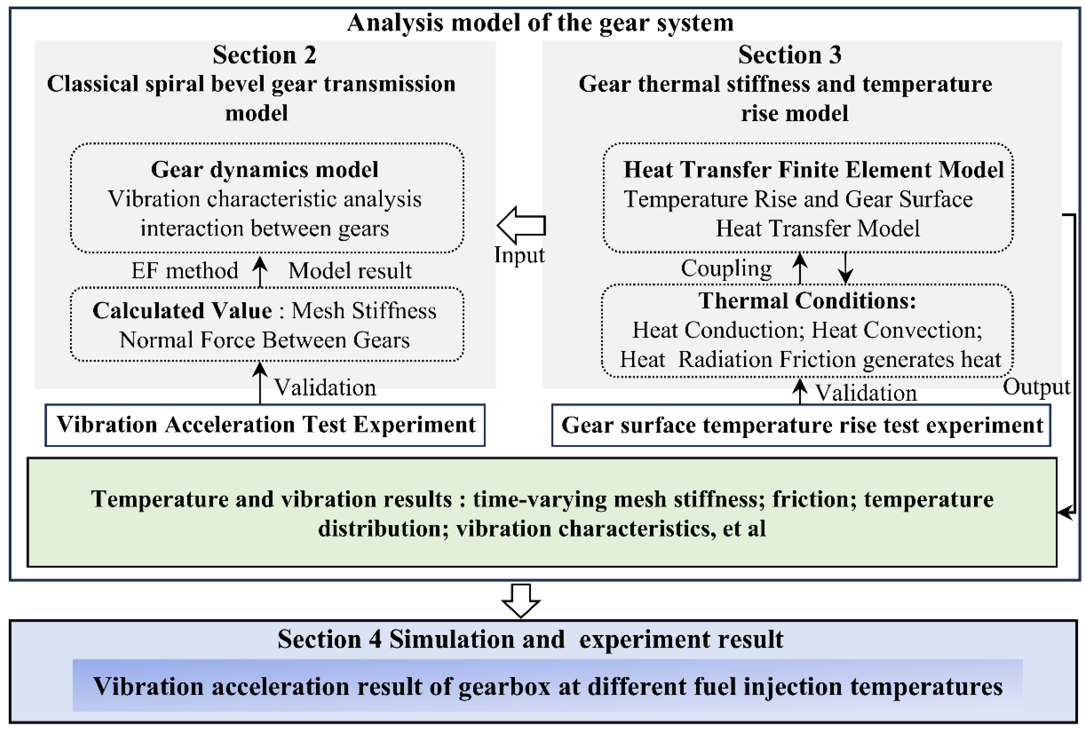
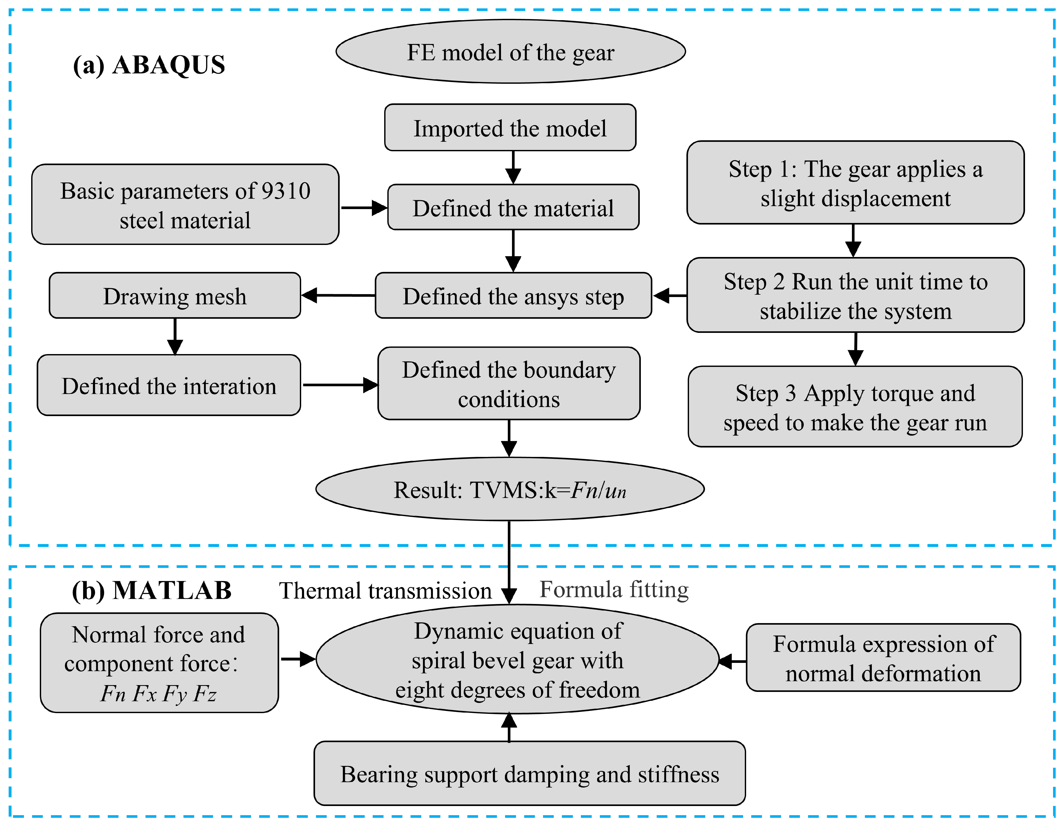
Figure 1 presents the overall process flow.
This study combines experimental and theoretical analyses to investigate the influence of heat on time-varying mesh stiffness. By integrating the eight-degree-of-freedom dynamic differential equations, the effect of different gear body temperatures on vibration characteristics is examined. In the experiments, three lubricants with varying temperatures were sprayed at the meshing points, and the gear body was heated to different temperatures. The vibration acceleration of the gearbox was measured using an acceleration sensor for analysis. The overall flowchart is shown in
Figure 1.
Due to relative sliding between meshing tooth surfaces, frictional heat is generated, leading to a rise in the temperature.
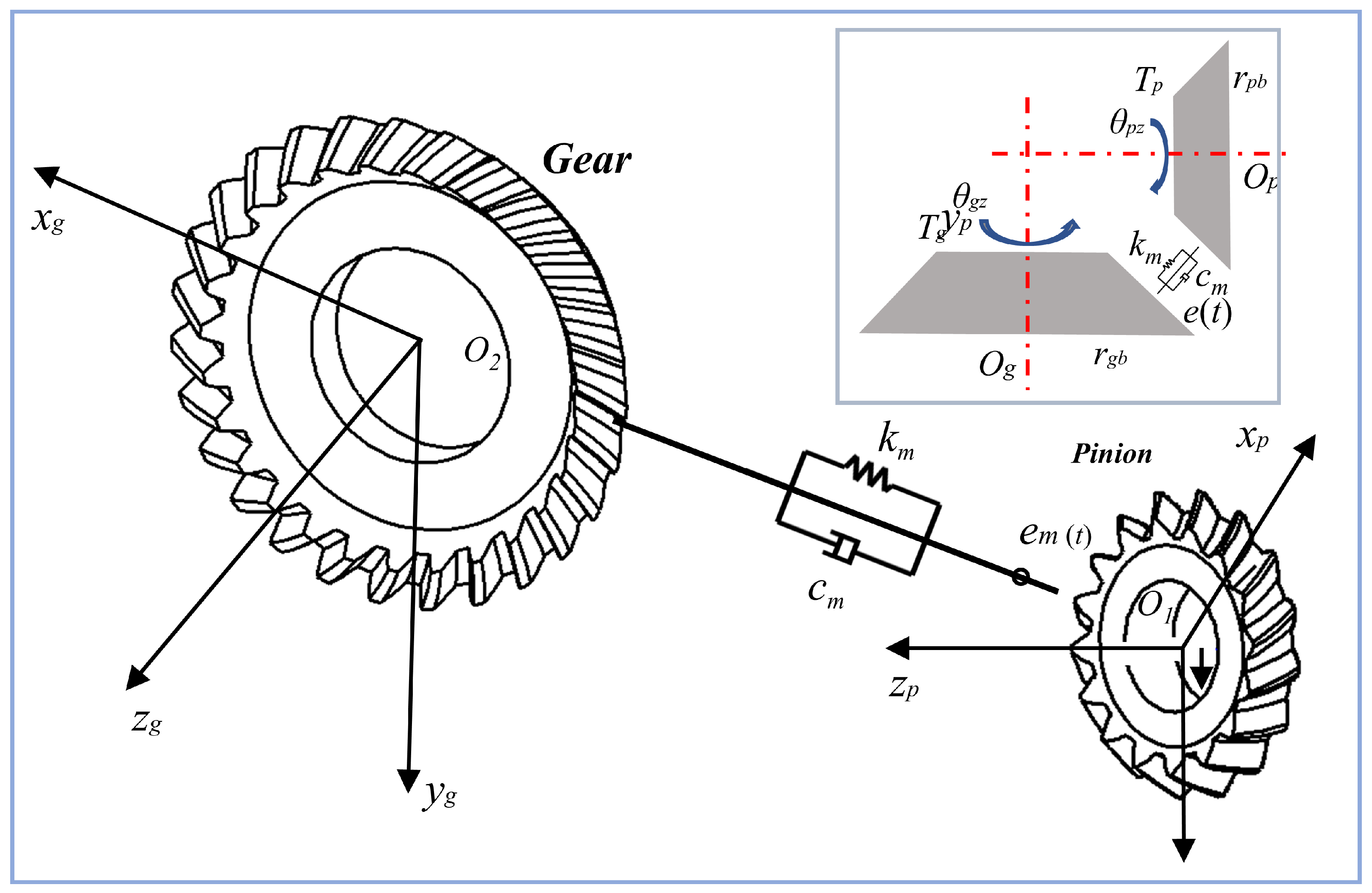
Figure 2 presents the gear dynamic model incorporating thermal stiffness. The left section illustrates the dynamic modeling process of the spiral bevel gear, while the right section depicts the establishment of thermal stiffness. The dynamic model of the spiral bevel gear is constructed by integrating thermal stiffness. The overall dynamic model is formulated as follows [
27].
A dynamic model of the spiral bevel gear with 8 degrees of freedom (DOF) is established, which includes six translational and two rotational directions. The degrees of freedom of the system are determined by Equation (1).
The parameters of the spiral bevel gear are shown in the parameter table. The eight degrees of freedom include the translation movements of the large gear in three directions, the translation movements of the small gear in three directions, the rotational motion of the large gear about its axis, and the rotational motion of the small gear about its axis. The motion directions for each degree of freedom are shown in Equation (1).
The deformation values are shown as follows:
The tooth profile error is represented by a sine harmonic function.
The expression for transmission error is given in Equation (3). The normal force is determined by the time-varying mesh stiffness and time-varying damping. The first equation in Equation (4) represents the normal force between the spiral bevel gears. The subsequent equations describe the components of the normal force along the three directions. The directions of these components are determined by the angle between the pair of gears:
The time-varying meshing stiffness is defined as:
The time-varying mesh stiffness is solved using the finite element method. It is obtained through transmission analysis based on the established finite element model of the spiral bevel gear. The calculated time-varying mesh stiffness is fitted using the following equation, which involves the average mesh stiffness of the meshing gear pair.
The variation in time-varying mesh stiffness of the spiral bevel gear is determined by the rotational speed:
By integrating the above equations, the differential equation of the eight-degree-of-freedom vibration dynamics of the spiral bevel gear is obtained, as shown in Equation (7).
Equation (7) represents the eight-DOF dynamic model of the spiral bevel gear. The model is obtained by balancing the normal force between the tooth surfaces and the forces exerted by the bearings on the gear shaft. The solution to the above model is obtained using the fourth-order Runge–Kutta method.
The specific values are provided based on the relationship between transmission error and time-varying meshing stiffness in the subsequent text.
Figure 2 illustrates the method for analyzing gear vibration under different body temperatures through computational analysis.
Dynamic transmission error, as a primary parameter affecting the dynamic performance of spiral bevel gears, plays a significant role in dynamic simulations of spiral bevel gears. The dynamic transmission error of spiral bevel gears significantly impacts the analysis of their dynamic meshing performance. The transmission error is defined as:
where
φ10 and
φ20 represent the initial angular positions pinion and gear, respectively, while
φ1 and
φ2 represent their actual angular positions.
i21 denotes the transmission ratio.
Figure 3 is a schematic diagram of the dynamic model of the spiral bevel gear. Gear transmissions are designed to be conjugate, ensuring a constant transmission ratio. Therefore, under ideal conditions, transmission error is minimal. However, in practical applications, external forces affect the gears, causing deviations from the intended transmission ratio and resulting in dynamic transmission error. The linearity of this error can be derived as follows:
The above equation can be transformed as follows:
The first few terms of the above equation are taken for further analysis as follows:
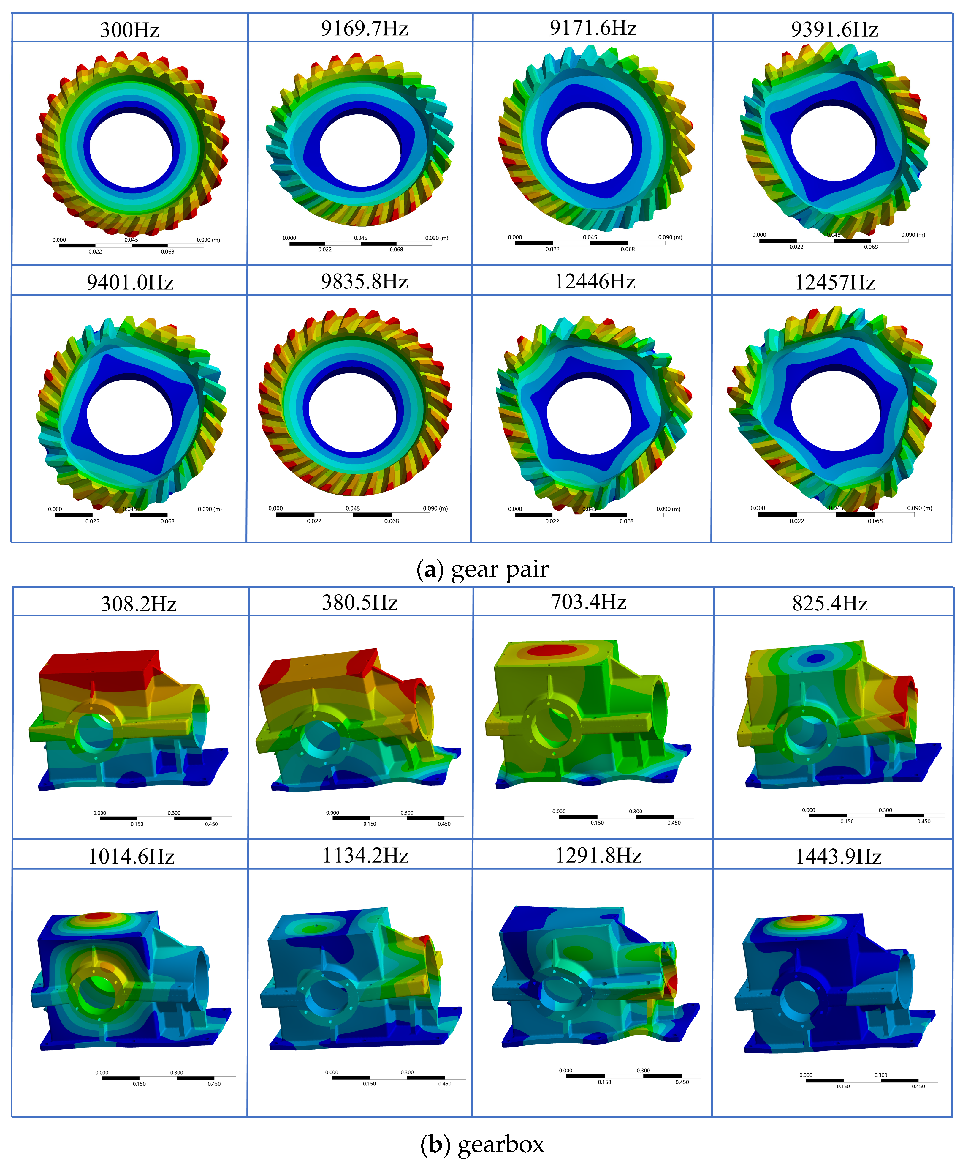
Figure 4 shows the first eight modal shapes of the gearbox and gears obtained through finite element analysis. The analysis allows for the examination of vibration behavior at each modal level. The vibration sensors were positioned at the input and output shaft locations of the gearbox based on the modal shapes.
Different natural frequencies correspond to different nodal diameter vibration modes. As the natural frequency increases, the nodal diameter vibration modes for the first to eighth modes are 2, 4, and 6 nodal diameter modes, respectively. The maximum vibration mode of the gearbox is primarily manifested on the upper external side of the shaft position.
The general dynamic equation is defined as [
31]:
Equation (12) is the shorthand for the dynamic equation of the spiral bevel gear. The coefficients represent various computational parameters, including mass, damping, stiffness, and displacement force parameters. The overall calculation formula relates the forces and moments between the components.
3. Gear Thermal Meshing Stiffness Model
The equivalent mass in Equation (12) is determined by its own parameters and is not affected by temperature changes. The effect of heat on the equivalent mass can be neglected. Heat significantly impacts the time-varying meshing stiffness and damping. The changes in these parameters due to heat generation on the tooth surface, in turn, influence the vibration characteristics of the gear.
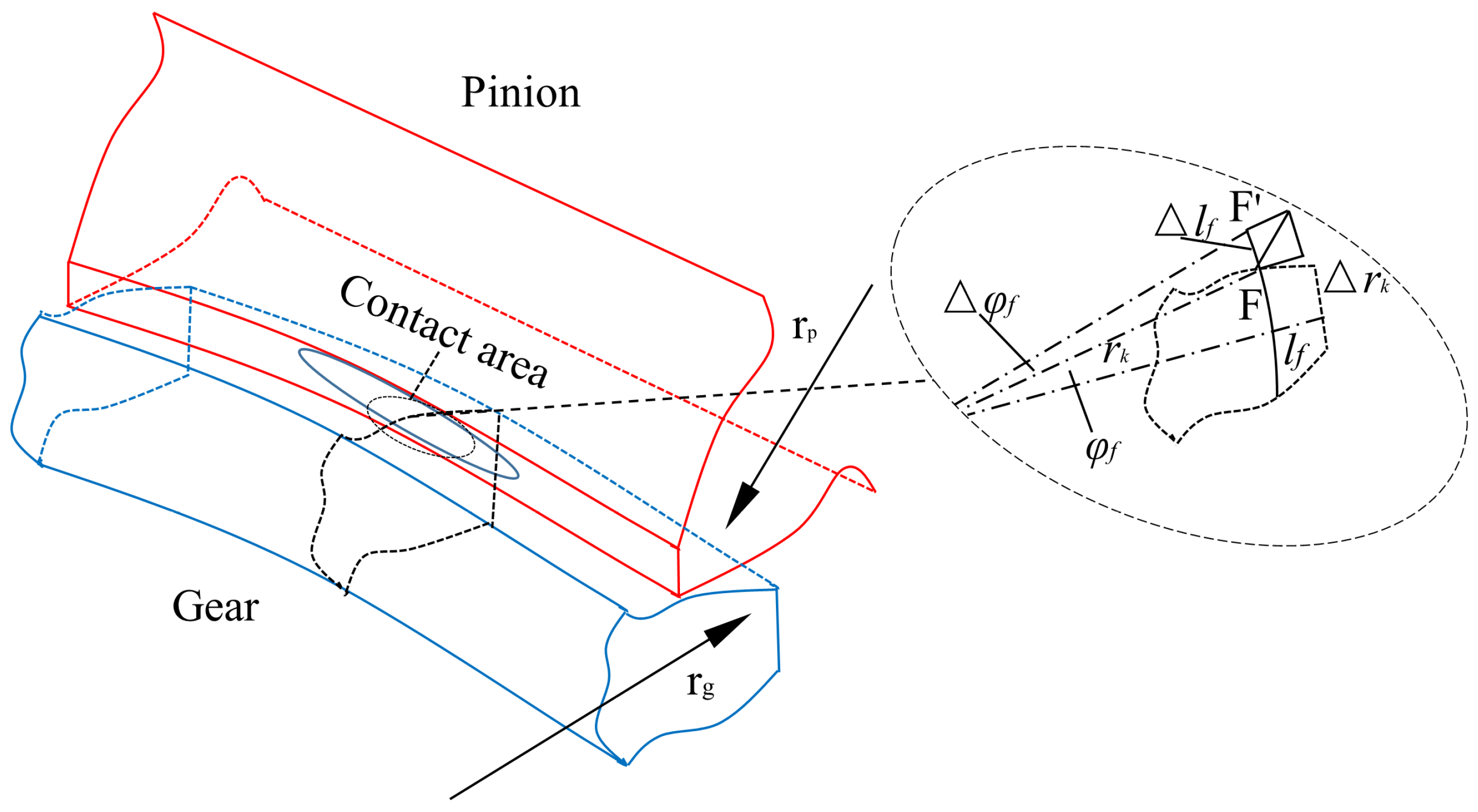
Figure 5 illustrates the thermal deformation of the tooth connect after expansion due to heating.
Reference [
31] established a relationship between the rise in tooth surface temperature and expansion. To assess how temperature increases affect the dynamic parameters of spiral bevel gears, the gear’s thermal stiffness after heating must be taken into account. Thermal stiffness is defined as the ratio of the normal force on the tooth surface to the normal thermal–elastic coupling deformation. This force can be obtained through finite element analysis of scuffing, with the main focus being the thermal–elastic coupling deformation of the gear.
The contact point
F on the tooth surface moves to point
F′ due to thermal expansion. This thermal expansion is divided into deformation along the contact circumference and displacement along the radial direction. Due to the properties of involute gears, the angle of the contact position can be expressed as:
The thermal expansion of the gear along the radial direction is . The thermal expansion along the circumferential direction is . The total angular change at the contact position is . Based on the above analysis, the position of the contact point after thermal expansion can be accurately determined, given that the gear tooth surface experiences significant thermal expansion.
Therefore, the thermal expansion of the tooth part
rbf and the thermal expansion of the gear’s base circle part
rb are expressed separately.
Based on the content from the reference [
30], the thermal expansion of the base circle can be expressed as:
where
is the thermal expansion along the pitch circle.
From the above analysis, it is clear that temperature rise plays a crucial role in calculating gear thermal deformation. This study combines both experimental and simulation approaches to determine the tooth surface temperature. The temperature at the gear bore can be calculated using finite element methods.
By converting the thermal expansion quantities to a Cartesian coordinate system, the corresponding thermal expansion components can be derived.
When heated, both gears experience thermal expansion, resulting in equivalent thermal stress. This thermal load is the product of the tooth surface stiffness and thermal expansion, and the thermal-elastic coupling stiffness of the straight gear captures this relationship. During the calculation, a thermal–elastic coupling coefficient must be determined. Based on literature analysis, this study introduces a thermal–elastic contact coefficient
Et for spiral bevel gears, which differs from that for cylindrical gears due to variations in contact modes. This coefficient facilitates the conversion of thermal loads into thermal-elastic coupling loads. The calculation process follows the simulation procedures outlined in the literature, with the necessary parameters provided in
Table 1.
By solving for both the thermal deformation and elastic deformation of the tooth surface, the thermal–elastic coupling stiffness of the spiral bevel gear, taking into account the temperature rise, can be determined. The single-tooth thermal-elastic stiffness and the overall thermal stiffness are as follows:
The formulas in this section are substituted into Equation (6) to calculate the thermo-dynamic model of spiral bevel gears under thermal conditions. The normal contact force and elastic stiffness are determined using finite element methods. Building on previous derivations, the thermal–elastic deformation of the two tooth surfaces is calculated by analyzing the temperature rise at different relative positions of the gears.
Figure 6a illustrates the process of calculating time-varying meshing stiffness through finite element analysis. The time-varying meshing stiffness at various gear body temperatures is computed using the formulas mentioned above.
Figure 6b shows how the time-varying meshing stiffness is incorporated into the dynamic model. The effect of time-varying meshing stiffness on the vibration behavior of the spiral bevel gear is then analyzed through theoretical investigation.
4. Result and Discussion
The experiment used a vibration acceleration sensor to detect the vibration acceleration at the input and output shaft positions of the gearbox. The frequency of the vibration acceleration sensor was 20 kHz. The data collection time for each group is 30 s. The hydraulic station is equipped with a heating device to raise the oil temperature, allowing for oil lubrication at different temperatures.
Table 2 shows the basic parameters of a pair of spiral bevel gears.
Table 3 shows the basic processing parameters of spiral bevel gears.
Additionally, a speed-torque sensor was deployed to measure transmission efficiency. The experiment was set at the different speeds (1200 r/min, 800 r/min and 400 r/min), torques (20 N·m, 60 N·m and 100 N·m), and oil temperatures (40 °C, 60 °C and 80 °C). A total of 27 test groups were conducted. Since this paper aims to determine the vibration behavior of the gearbox at different operating temperatures, vibration acceleration data under non-temperature conditions will not be analyzed in detail.
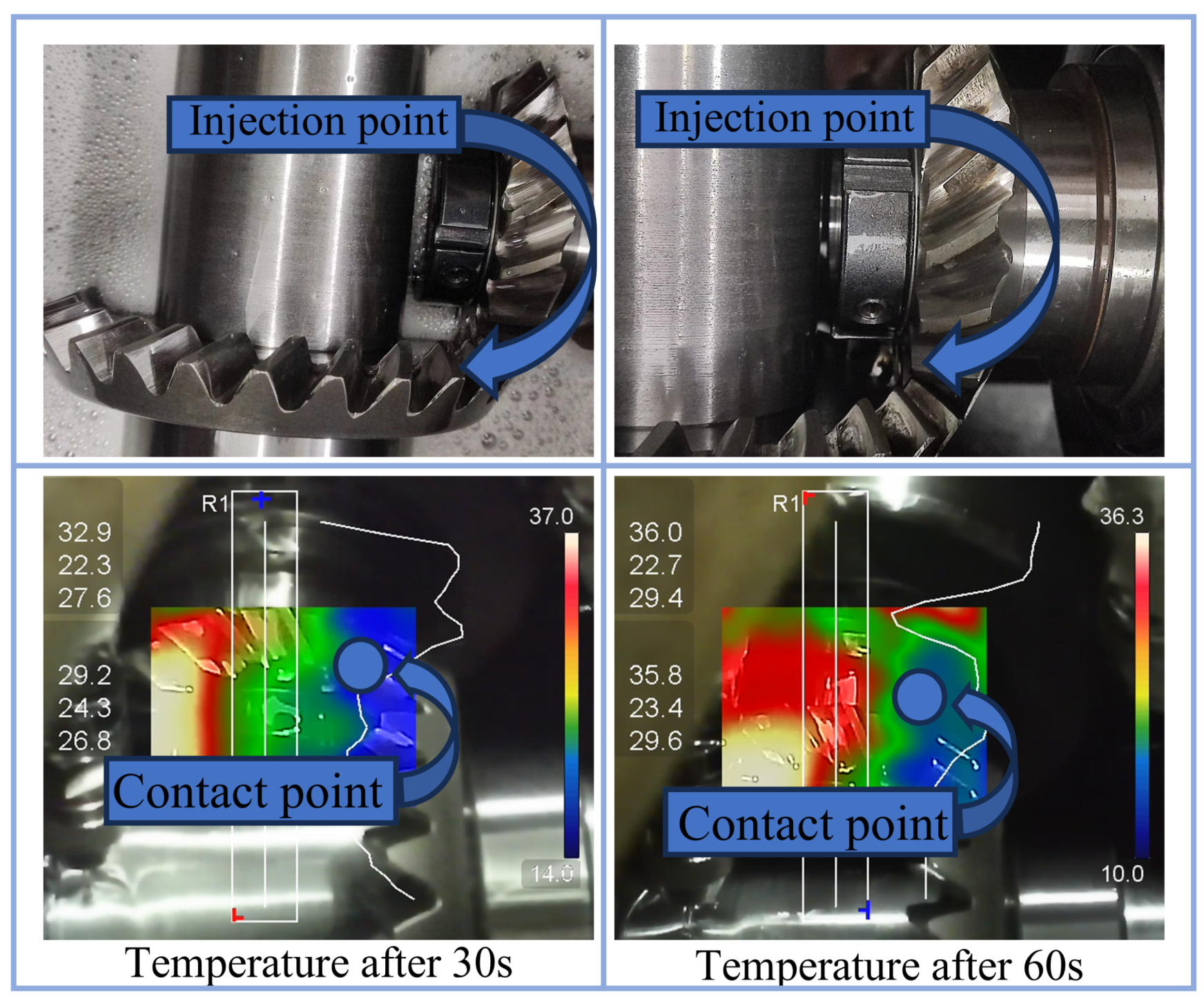
Figure 7 shows the vibration acceleration detection equipment and data transmission system. Vibration acceleration measurements were taken after applying different temperatures to the gear body.
Figure 8 presents the results after the oil at 40 °C was sprayed for a period, followed by opening the cover for inspection.
After opening the cover, the tooth surface temperature dropped slightly but was maintained at 37 °C. Therefore, the tooth surface temperature during the gear’s operation can be accurately ensured. The oil spray was applied at the meshing point of a pair of gears. The following setup was used for the vibration acceleration testing of spiral bevel gears at different body temperatures.
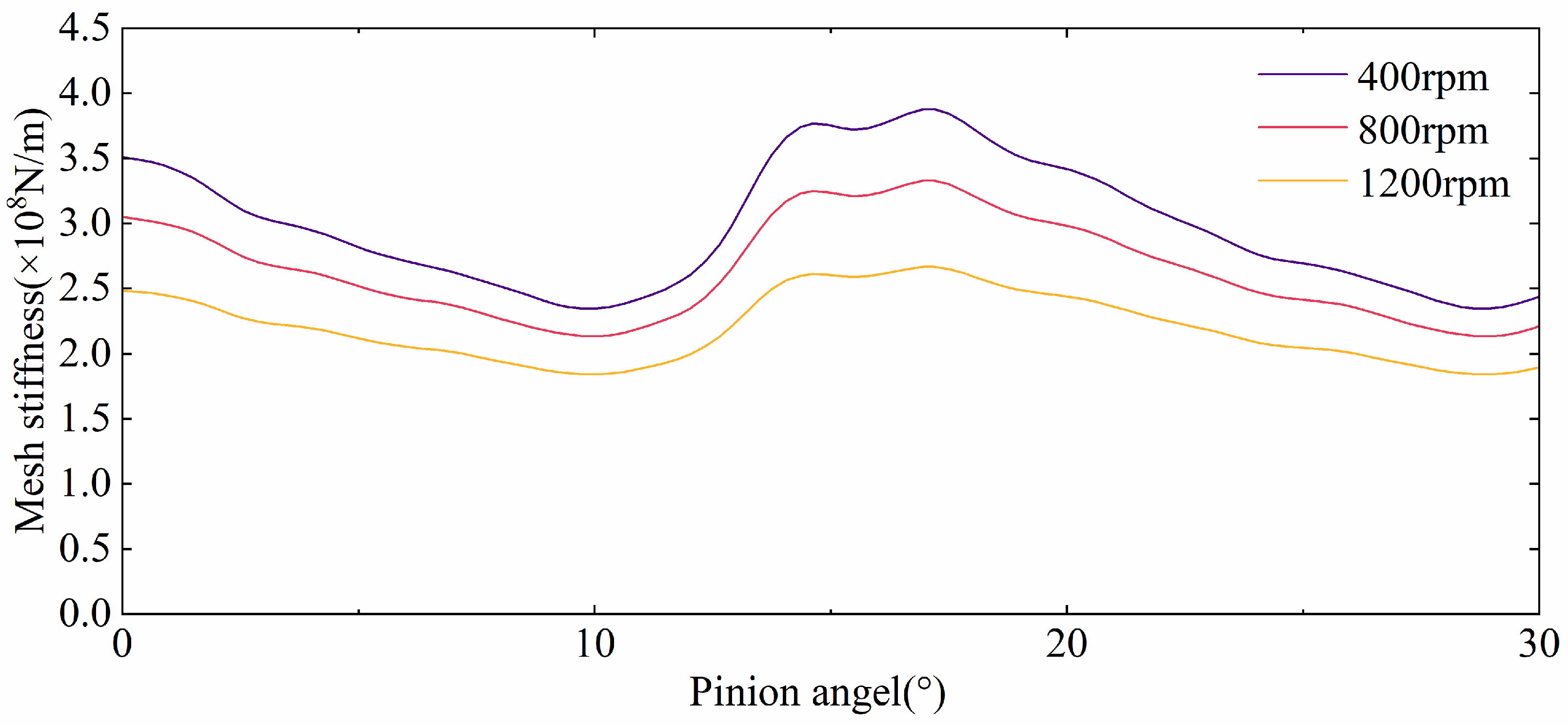
From
Figure 9, it can be observed that as the tooth surface temperature increases, the time-varying meshing stiffness decreases. There is a linear relationship between stiffness and frequency. In the calculation of the dynamic equation for the spiral bevel gears, as the time-varying meshing stiffness decreases, the natural frequency also decreases.
Based on previous research findings [
31], a theoretical simulation study of time-varying meshing stiffness was conducted under the same initial temperature, with varying speeds and the same torque. Under identical conditions, the higher the speed, the greater the tooth surface temperature rise within the same time period.
The results are presented in
Figure 9. As the gear body temperature rises, the time-varying meshing stiffness also increases, causing more pronounced tooth surface vibrations.
Figure 10 shows that with higher temperatures, the vibration acceleration amplitude becomes more significant under the same conditions.
From
Figure 10, it can be seen that as the temperature increases, the vibration acceleration amplitude becomes more pronounced under the rotational speed 1200 r/min. Both temperature and load exhibit significant effects on system vibration. At high temperatures (80 °C), the vibration acceleration amplitude increases markedly, accompanied by more intense fluctuations. At medium temperatures (60 °C), the amplitude decreases moderately, indicating a relatively stable system. At low temperatures (40 °C), the amplitude is minimal, suggesting that vibration is effectively suppressed. As the load increases from 20 N·m to 100 N·m, the vibration acceleration progressively intensifies, with the most pronounced effect observed under high-temperature conditions, indicating that higher loads exacerbate system vibration. In summary, the combination of high temperature and high load tends to induce severe vibration, whereas low temperature and low load result in minimal vibration. Therefore, in practical applications, it is crucial to control the gear body temperature to mitigate vibration risks and extend the service life of the equipment.
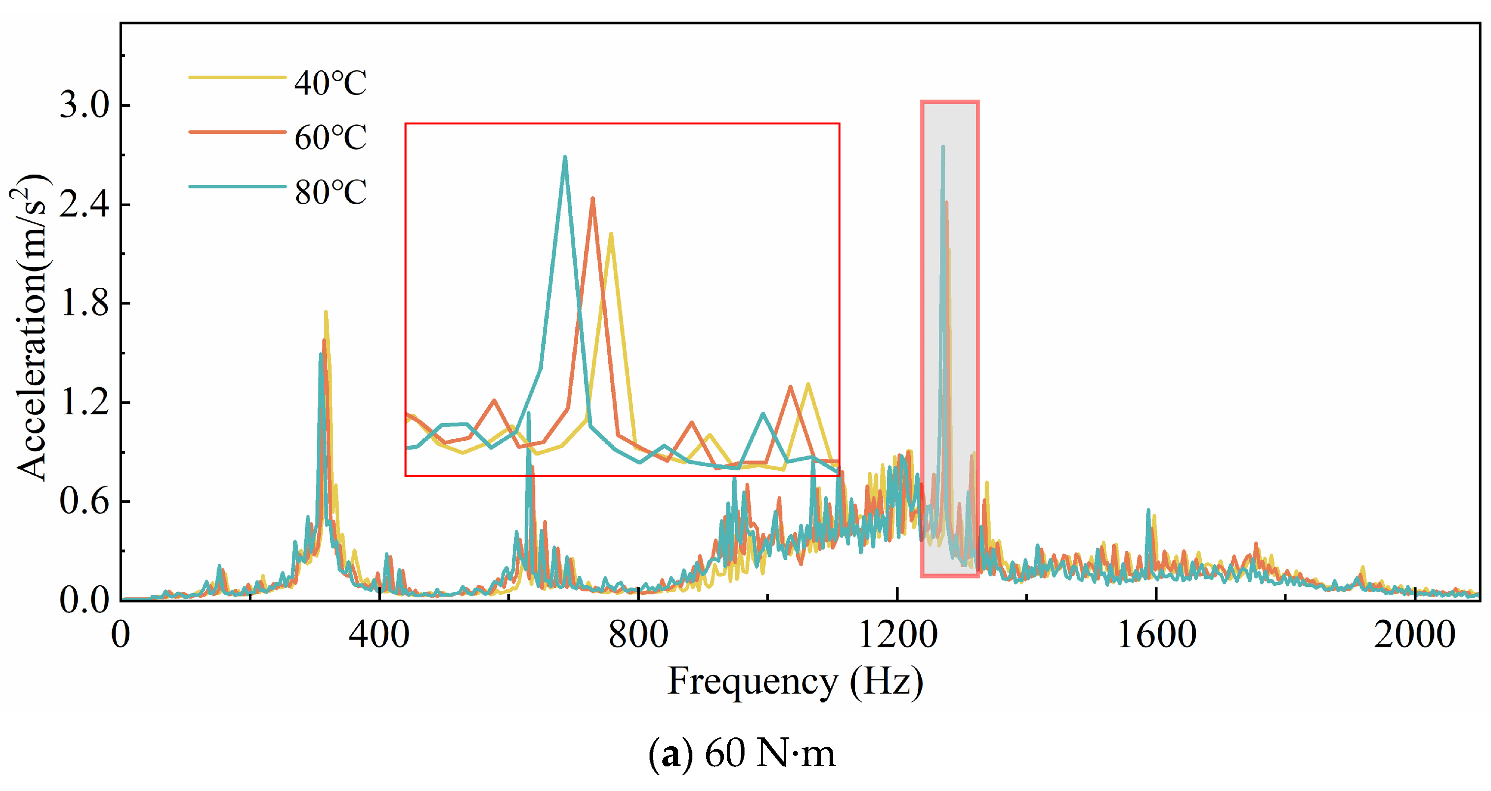
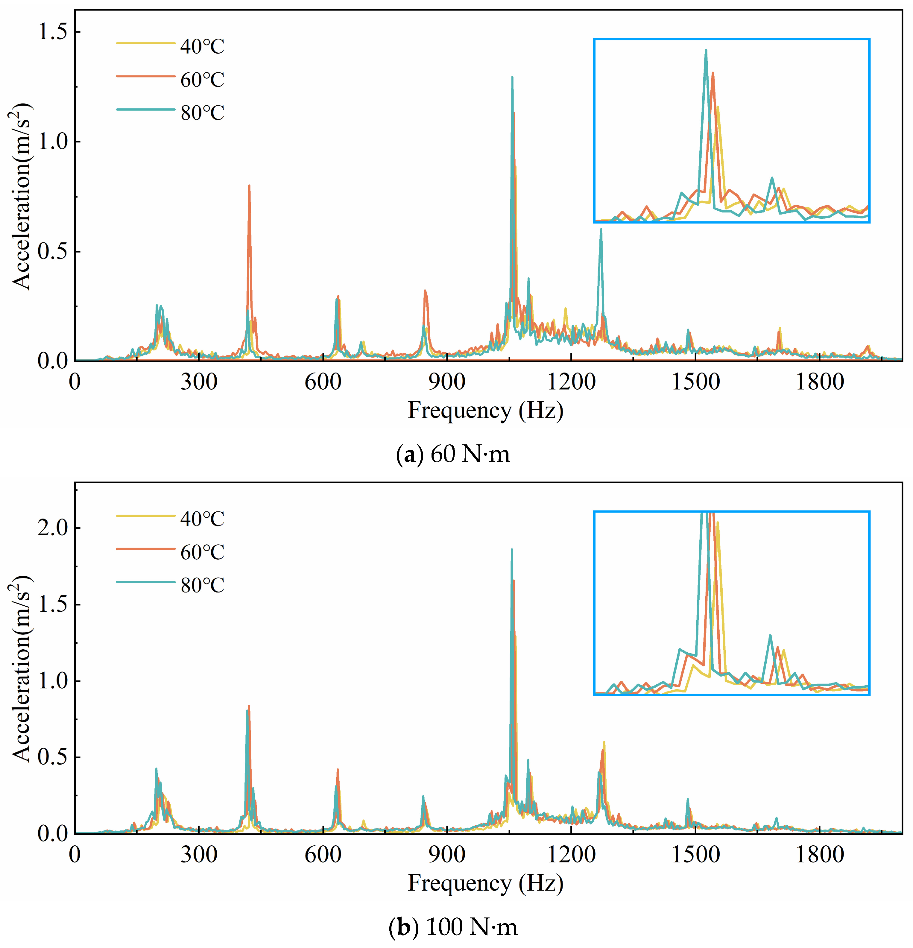
Figure 11 shows the vibration acceleration spectra at the rotational speed 1200 r/min. The impact of temperature on the vibration acceleration spectra exhibits a clear frequency-dependent behavior, with significant effects observed in the medium-to-high frequency range. Under high-temperature conditions (80 °C), the amplitude of vibration acceleration increases significantly across all frequency bands, with the most severe vibrations occurring in the medium-frequency range of 800 Hz to 1200 Hz. In contrast, low temperatures (40 °C) effectively suppress vibrations in the low- and high-frequency ranges, although noticeable responses are still observed in the medium-frequency range. In practical applications, temperature control is essential to mitigate the adverse effects of high temperatures on gear system vibrations, thereby reducing vibration risks and extending equipment service life. Additionally, as the temperature increases, the meshing frequency tends to decrease, which is consistent with the analytical results presented earlier.
Figure 12 illustrates the distribution of vibration acceleration at the rotational speed 800 r/min. Similar to the conclusions drawn from
Figure 9, the vibration acceleration amplitude increases with the rise in gear body temperature, leading to more severe vibrations.
Figure 13 gives the vibration acceleration spectra at the rotational speed 800 r/min. As the temperature increases, the amplitude of vibration acceleration decreases, and the vibration behavior exhibits a strong correlation with frequency.
Compared to
Figure 11, the amplitude is notably reduced, indicating less severe vibrations at lower rotational speeds. The reduction in frequency is attributed to the decrease in meshing stiffness caused by the lower temperature.
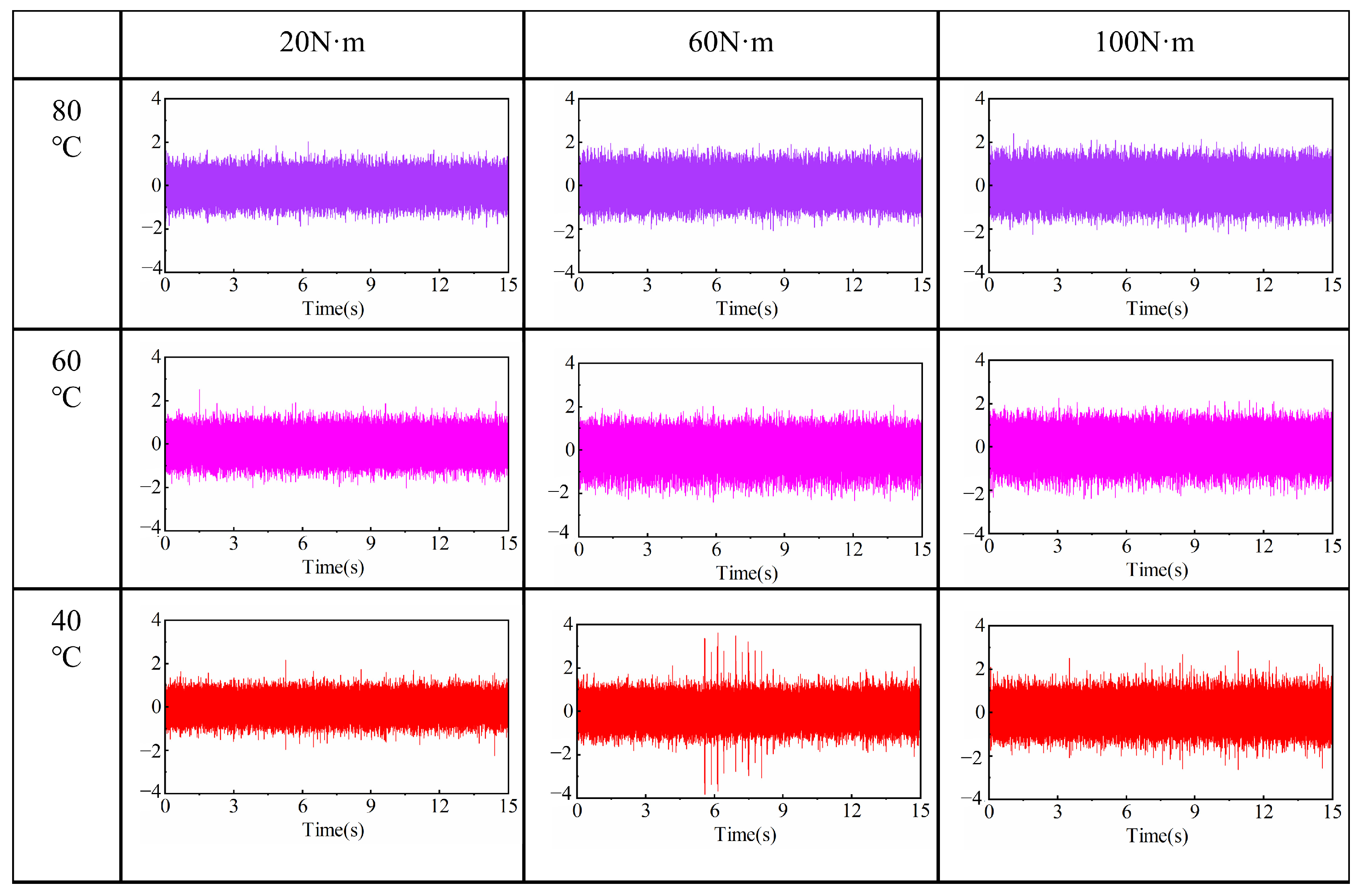
Figure 14 presents the time-domain vibration acceleration at the rotational speed 400 r/min. Compared to 1200 r/min and 800 r/min, the amplitude of vibration acceleration is further reduced. However, as the gear body temperature increases, the vibration acceleration becomes more intense, making the system more prone to various failures.
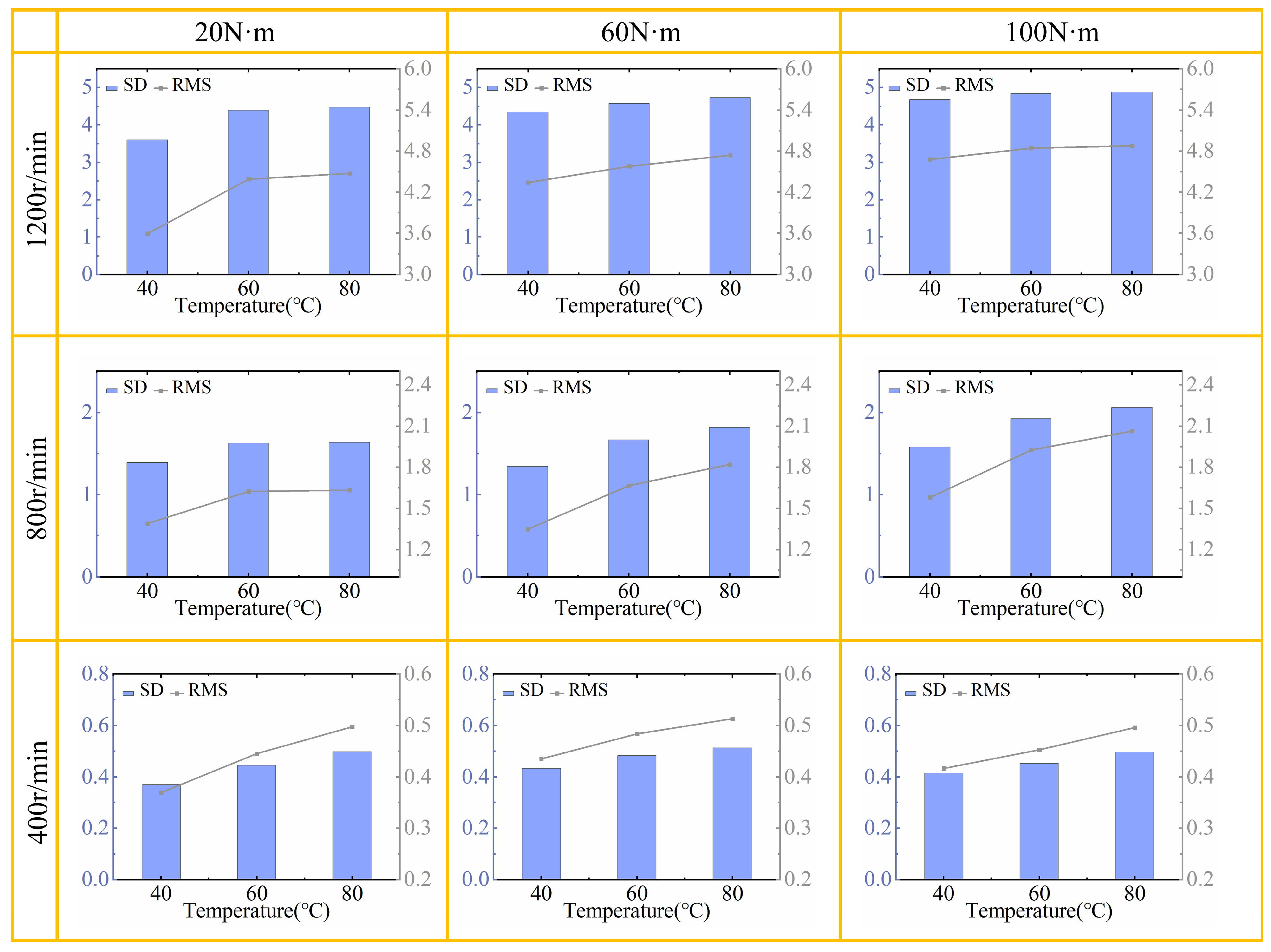
Figure 15 presents the variance and root mean square (RMS) values of vibration acceleration under all operating conditions. Each graph reflects the data variations at three different operating temperatures for a specific condition. As the gear body temperature increases, two aspects are observed: First, both the standard deviation and RMS values increase, indicating a rise in vibration intensity. Second, as the body temperature increases, the rate of change in standard deviation and RMS values decreases, suggesting a reduced trend in vibration intensity changes.
At 1200 r/min and 20 N·m, the standard deviation and RMS values increase by 22.03% and 24.3%, respectively, with the rising temperature. At 1200 r/min and 60 N·m, these values increase by 5.45% and 8.99%. At 1200 r/min and 100 N·m, the increases are 3.55% and 4.33%.
At 800 r/min and 20 N·m, the standard deviation and RMS values increase by 16.93% and 17.54%, respectively, with rising temperature. At 800 r/min and 60 N·m, the increases are 2.37% and 3.52%. At 800 r/min and 100 N·m, the increases are 2.18% and 3.04%. At 400 r/min, the results also conform to the above analysis. As the torque increases, the increase in vibration amplitude becomes smaller, and the rate of change decreases.
5. Conclusions
The theoretical analysis of spiral bevel gears found that as the gear body temperature increases, the meshing stiffness increases. The increase in meshing stiffness leads to a decrease in the gear’s natural frequency.
Experimental results demonstrate that as the gear body temperature increases, the rate of change in standard deviation and RMS values gradually decreases, indicating a slower growth in vibration intensity. Nevertheless, both standard deviation and RMS values continue to rise, reflecting an overall increase in vibration intensity. For example, at 1200 r/min, the standard deviation and RMS values increase by 22.03% and 24.3% at 20 N·m, 5.45% and 8.99% at 60 N·m, and 3.55% and 4.33% at 100 N·m. At 800 r/min, the increases are 16.93% and 17.54% at 20 N·m, 2.37% and 3.52% at 60 N·m, and 2.18% and 3.04% at 100 N·m, with similar trends observed at 400 r/min.
Validation results further confirm that higher temperatures lead to a reduction in natural frequency, an increase in vibration frequency, and an amplification of vibration acceleration. This method effectively captures the impact of temperature on vibration intensity, offering valuable insights into how gear body temperature influences system vibration and scuffing behavior.


