Abstract
In electric vehicles (EVs), bearings in traction motors are increasingly prone to electrical damage under operational currents and voltages, leading to accelerated wear and reduced lifespan. This study examines the extent of bearing damage under low-speed, electrically charged conditions to understand wear behavior at boundary lubrication better. Bearings were driven at low speed by a motor, with inner and outer rings connected to a pulsed power supply’s positive and negative terminals, simulating real-world shaft voltage conditions. The applied electrical parameters included voltages from 5 V to 240 V and frequencies of 10 kHz, leading to voltages at the bearing peaking between 0.1 and 12 V measured by an oscilloscope and multimeter. The tested bearings were disassembled, and scanning electron microscopy (SEM) was used to assess the damage associated with varying electrical stresses. The results revealed distinct wear patterns and degradation effects when the shaft current and peak voltage reached 2.5 A and 12 V, emphasizing the critical need for protective strategies. Future work will focus on evaluating the impact of higher rotational speeds and controlled power supply conditions to analyze the effects of increased power supply settings and compare outcomes to low-speed scenarios.
1. Introduction
Electric vehicles (EVs) operate under unique electrical and mechanical conditions, which pose new challenges to the durability and performance of motor bearings. A critical issue in EV applications is the generation of shaft voltage and resulting bearing currents, which can lead to electrically induced bearing damage (EIBD) [1]. These currents, often caused by common-mode voltages from inverter-driven motors, can discharge across the lubricated contact surfaces in the bearing, causing localized pitting, fluting, and grease degradation [2].
Similar damage mechanisms have also been observed in wind turbines [3], where bearing currents caused by shaft voltage lead to electrical erosion such as pitting and surface fatigue. These discharges often occur when the lubricant film becomes thin, allowing current to pass through rolling contacts [4]. The extent of damage is closely related to lubrication conditions and electrical input, which is also relevant to EV motor bearings. As EV adoption grows, understanding the mechanisms behind EIBD becomes increasingly important [5]. In inverter-driven motors, shaft voltage can generate bearing currents that cause damage like pitting, frosting, and grease degradation [6]. These discharges produce localized heat and reduce both surface hardness and lubricant insulation, increasing the chance of repeated failure. Even weak currents can gradually erode bearing surfaces due to high current density at contact points.
Various experimental and modeling approaches have been employed in recent studies to investigate the mechanisms of EIBD. One line of research utilized a ball-on-disk tribometer under pulsed direct current (DC) voltage and low sliding speeds to study single discharge events [2]. This study employed a modified Mini-Traction Machine (MTM) setup with high-frequency (12.5 kHz) pulsed voltage to simulate discharge conditions in single elastohydrodynamic lubrication (EHL) contacts. This work also demonstrated that discharge location correlates with minimum film thickness and introduced a discharge energy model that accounts for dielectric properties and lubrication conditions. The result showed significant influences of film thickness in modulating discharge severity. Another study explored how motion patterns influence damage by using a 31 V direct current (DC) supply (0.5 A) in a ball-on-disk test rig [1]. It revealed that the rolling motion of the bearing caused more severe electrical pitting than continuous rotation, underlining the importance of kinematic conditions on EIBD progression. Complementary to single-contact tests, a combined experimental and numerical study investigated complete bearing systems under alternating current (AC) voltage (up to 5 kHz) and rotational speeds up to 1800 rpm [5]. The results aligned well with the simulation, confirming the relevance of modeling approaches for predicting damage under realistic e-motor conditions. Besides tests of the above coupon sample level, tests at a bearing component level have also been conducted. For instance, an experimental study tested bearings under sinusoidal alternating current (AC) voltage (3–8 V, 50 Hz) and speeds ranging from 100 to 800 rpm using a current-carrying tribometer [6]. It showed higher speeds and voltages led to more rapid breakdown and surface erosion. A comprehensive review summarized EIBD modes (such as frosting, fluting, and pitting) and associated electrical phenomena across nano- and macro-scales [7,8]. It also highlighted monitoring and modeling challenges and emphasized the need for multi-scale understanding [9].
Despite these extensive efforts, limited attention has been given to EIBD at low rotational speeds, such as 30 RPM or below. These conditions are also critical because the lubricant film may become extremely thin or unstable, potentially altering discharge behavior and increasing the risk of localized damage. This study uses controlled pulsed voltage and current to focus on bearing damage under low-speed conditions. By varying the magnitude of electrical input and examining the resulting discharge behavior and damage morphology, this work aims to better understand the impact of possible pulsed shaft voltage and current on bearing surfaces caused by EIBD mechanisms specific to a low-speed operation condition.
2. Methods
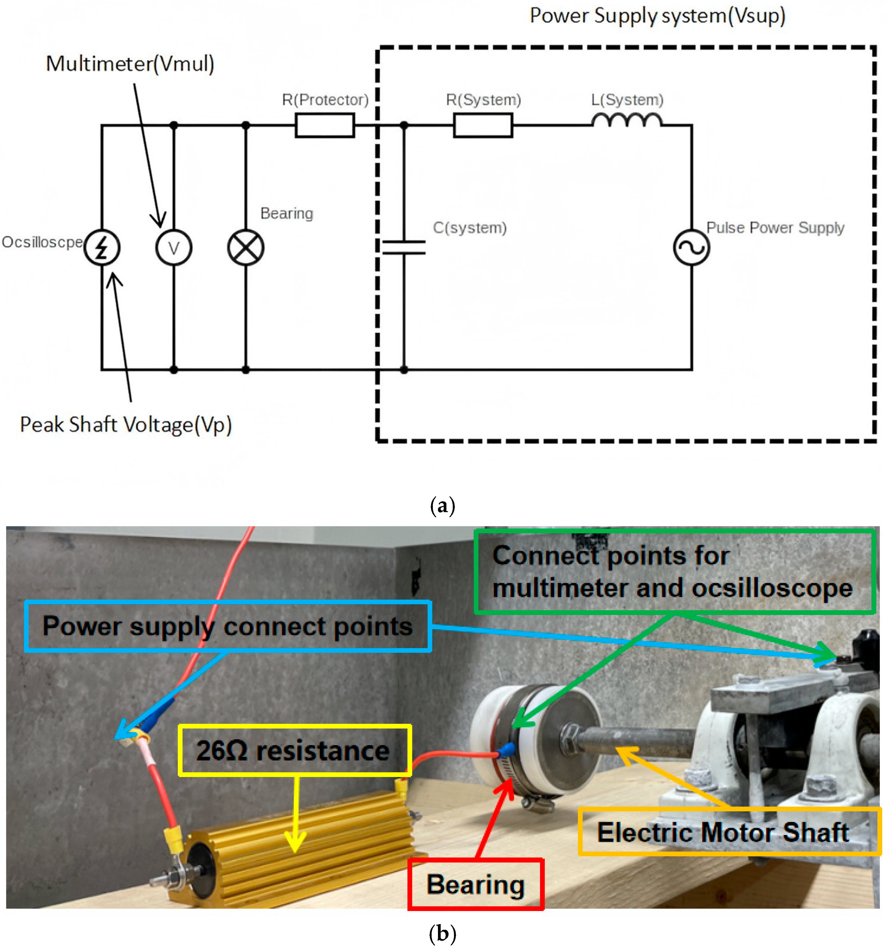
This study evaluates the effects of electrical currents and voltages on bearing wear and damage under controlled low-speed operating conditions. The experimental setup (Figure 1) utilized a motor system output at 60 RPM, with an additional 2:1 gear ratio connecting the motor to the test bearing. This configuration reduced the bearing’s rotational speed to approximately 30 RPM, replicating conditions of EV operations, such as slow maneuvers or stop-and-go traffic. These low-speed scenarios are particularly critical as they often subject bearings to unique stresses differing from those at higher speeds, where lubrication and inertial effects significantly mitigate damage.
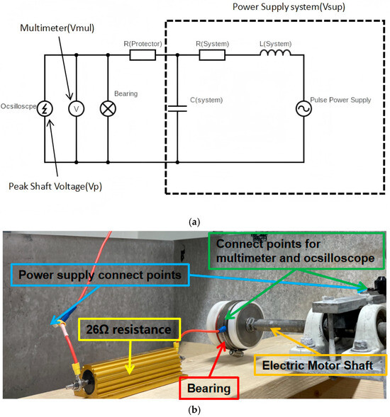
Figure 1.
(a) Circuit diagram of the low-speed bearing test and (b) the bearing setup.
To protect the electrical circuit and facilitate detailed resistance calculations during operation, a 26-ohm resistor was connected in series with the bearing. This parallel resistor provided additional circuit protection by limiting potential surges and allowed the precise measurement of the bearing’s equivalent resistance under varying electrical parameters. The resistor ensured the circuit remained stable throughout testing, enabling consistent and reliable data collection. The bearing system was powered by a programmable power supply, which served as the core component for generating controlled electrical conditions.
The power supply was explicitly configured to deliver pulse currents with adjustable parameters, including frequency, voltage, and current amplitude. This programmability allowed the simulation of various electrical stresses that bearings might encounter in EV systems [10]. The ability to manipulate these parameters was crucial for isolating the effects of each variable and understanding their individual and combined impacts on bearing damage. In addition to providing controlled electrical input, the power supply was integrated with monitoring equipment to ensure real-time observation of the applied electrical conditions. The system’s precise control and monitoring capabilities ensured that experimental conditions were consistent across all tests, reducing variability and enhancing the reliability of the results.
Due to the proximity of power electronics and rotating machinery, EV bearings are often exposed to electrical currents and voltages [9]. The setup mimicked these conditions by enabling the controlled application of pulse currents directly to the bearing’s inner and outer rings, simulating operational stresses experienced in electric motor systems at low-speed, electrically charged environments.
2.1. Experimental Design
This experiment used a DC pulse power supply in bipolar mode at 10 kHz. To survey the relationship between the power supply system and the bearing’s electric stresses, the power supply’s output voltage was systematically varied from 5 V to 240 V, and voltage readings at both ends of the bearing were recorded for analysis (Figure 1).
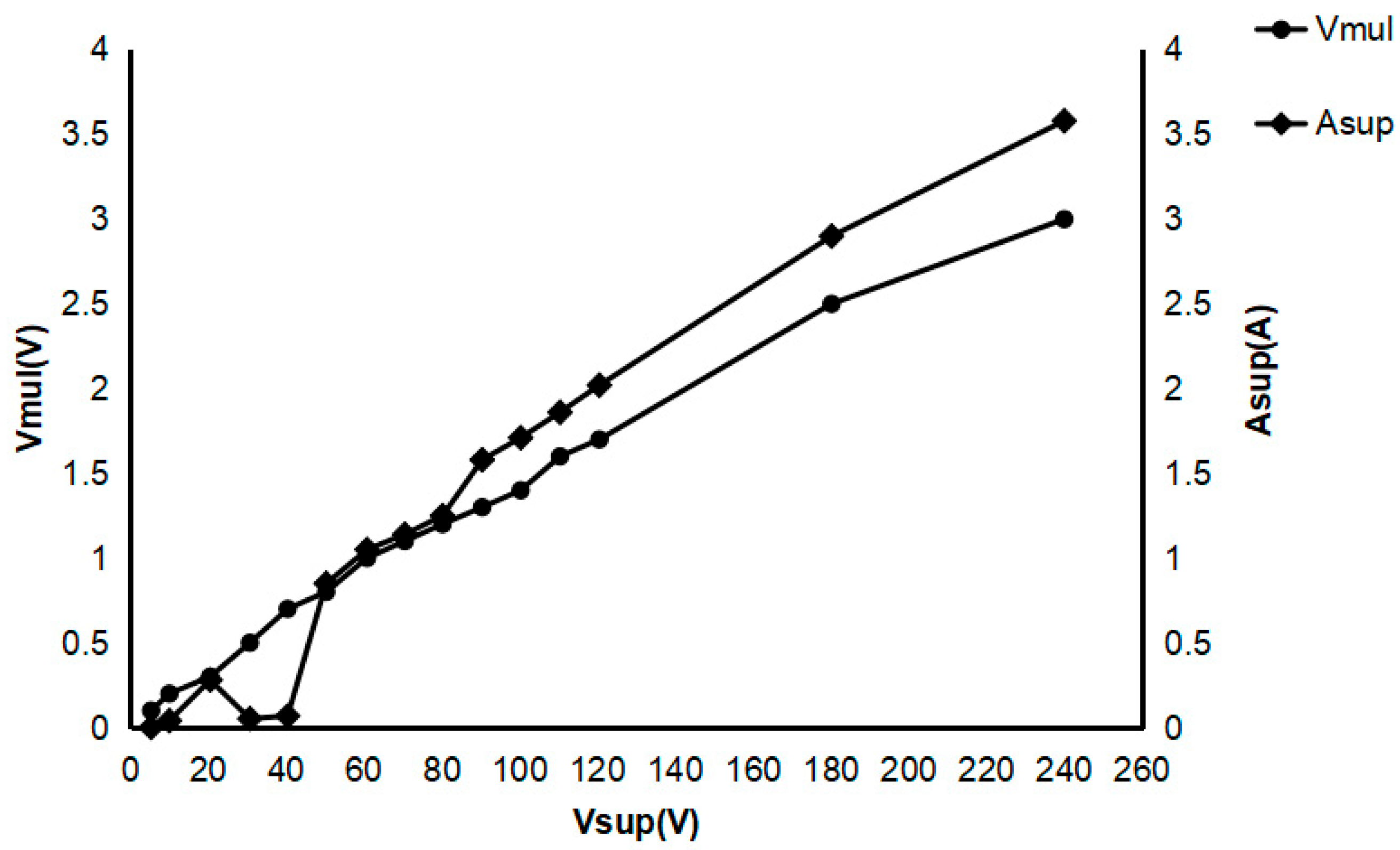
Figure 2 summarizes the results of this test, showing the voltage across the bearing terminals for each input voltage setting. At 5 V and 10 V, the terminal voltage across the bearing was minimal, indicating insufficient electrical stress to produce observable surface damage. The observed dip in current between 30 and 40 V (Figure 2) may be attributed to transient changes in the lubricant film’s conductivity or variations in contact resistance due to initial surface degradation. Further investigation is required to confirm this hypothesis.
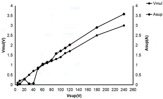
Figure 2.
The relation between the Vmul/Asup and Vsup.
Upon reaching 120 V, the terminal voltage stabilized at levels sufficient to induce measurable wear and degradation, thus serving as the baseline voltage for subsequent experiments. Tests at 180 V and 240 V were also conducted to explore further the relationship between voltage magnitude and the extent of electrical damage. All three tests were performed for 60 min each. The power supply voltages (Vsup) at 120 V, 180 V, and 240 V for 60 min were selected to assess the impact of increasing the bearing peak voltages (Vp) on bearing damage.
2.2. Measurement and Monitoring
During experiments, a multimeter and an oscilloscope were used to monitor and record electrical parameters (Figure 2 and Figure 3). The oscilloscope measured interval voltages across the bearing terminals. In contrast, the multimeter was configured to capture instantaneous voltage values. These measurements were essential for analyzing circuit electrical behavior and correlating parameters with observed bearing damage.
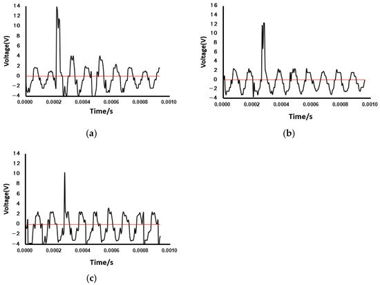
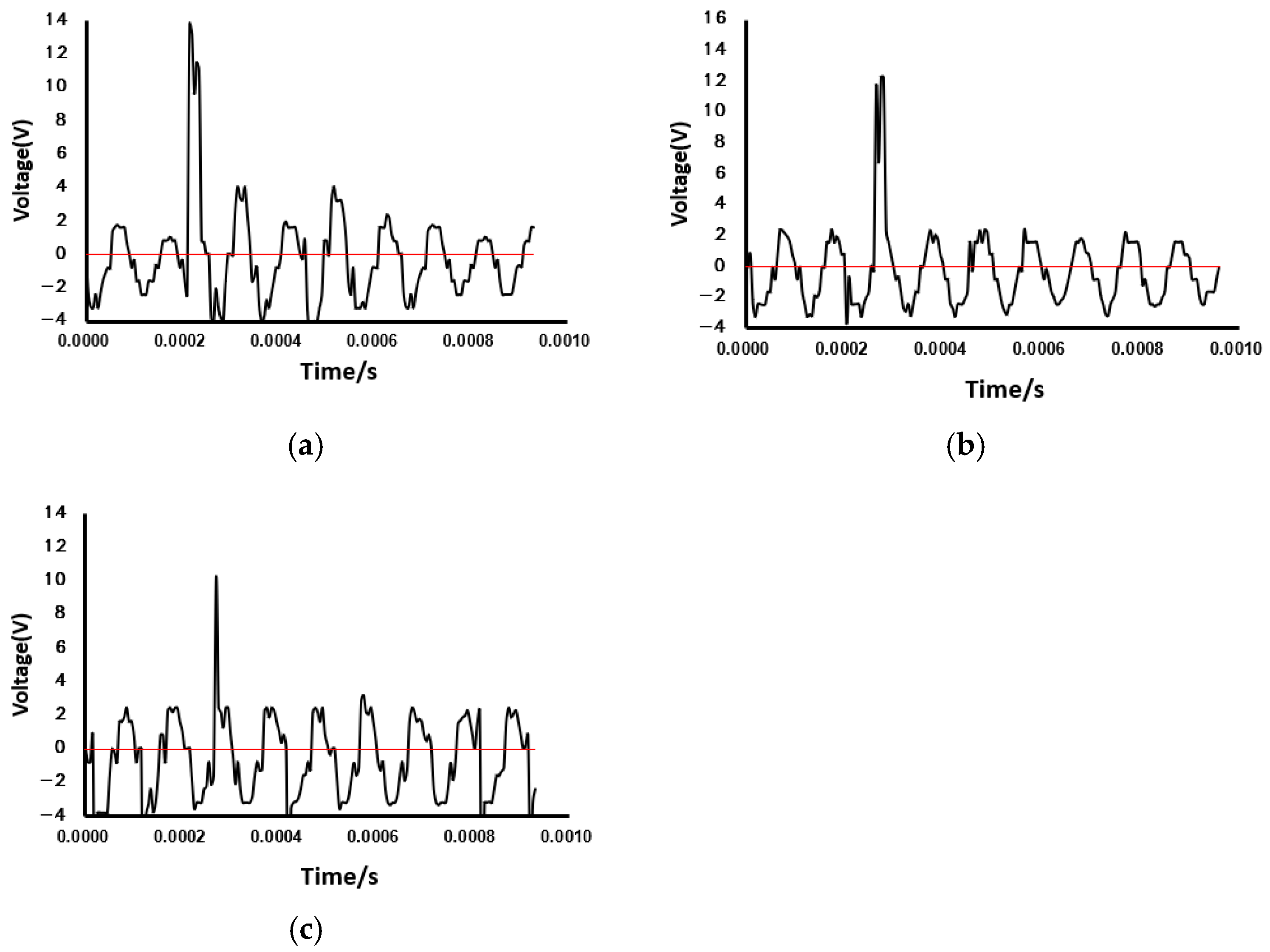
Figure 3.
A typical oscilloscope waveform on the bearing while the power supply shows 10 kHz bipolar: (a) 120 V test; (b) 180 V test; (c) 240 V test.
2.3. Bearing and Lubrication and Simulation
The bearing used in this study was a FAG deep-groove ball bearing, constructed from SAE 52100 chrome steel with a maximum operating speed of 9000 RPM, making it suitable for moderate-speed, high-load applications. The lubricant applied was SKF LGHP 2, a high-performance polyurea-based grease formulated for electric motor bearings. Each bearing was pre-lubricated with approximately 1 mL (15% of raceway volume) of grease. This setup represented a recommended condition for EV motor bearing applications [11,12].
2.4. Post-Test Analysis
After each test, bearings were carefully disassembled to evaluate surface wear and material damage induced by different electrical conditions. Inner bearing surfaces were examined using scanning electron microscopy (SEM) to observe surface morphology, providing microscopic insights into damage patterns under low-speed, electrically charged conditions.
3. Results
This section presents findings from experiments conducted under bipolar pulse current conditions at a 10 kHz frequency and voltages of 120 V, 180 V, and 240 V over 60 min. The analysis utilized oscilloscope measurements, optical microscopy, and SEM observations to assess the progressive effects of electrical stress on bearing surfaces.
The selection of a 10 kHz pulse frequency was deliberate and based on its relevance to electric vehicle (EV) applications. Modern EV inverters typically operate within an 8–12 kHz switching range [13]. By choosing 10 kHz, the experimental conditions realistically simulate the high-frequency electrical stresses experienced by motor bearings in service. This frequency is widely recognized in industry research [4,14] as representative of common inverter-driven environments and thus provides a technically justified and application-specific context for evaluating electrical discharge damage [7,15,16].
In this given system setup (Figure 1), the electrical current (Asup, read on the power supply panel) increased with the power supply voltage (Vsup) increasing, which also led to the increased voltage on the bearing (shown on the multimeter, Vmul). When the Vsup was 120 V, 180 V, and 240 V, the Asup and Vmul were 2.02 A and 1.7 V, 2.9 A and 2.5 V, and 3.58 A and 3.0 V, respectively (Figure 2). The voltage and current shown on the multimeter would only present the average readings on the bearing.
To correlate power supply voltage (120 V, 180 V, and 240 V) with shaft voltage, oscilloscope measurements were taken at both bearing terminals throughout the experiment. Voltage waveforms were recorded every 10 min, illustrating how electrical stress evolved for each setting. At 120 V, the oscilloscope waveform (Figure 3) remained stable with minimal fluctuations, indicating low interaction between electrical stress and the bearing surface, suggesting minor electrical activity within the bearing. Increasing to 180 V, the shaft voltage showed more variation with periodic spikes, suggesting increased electrical activity at rolling contact points and areas. After 30 min, moderate instability and occasional current spikes indicated potential localized surface degradation. At 240 V, shaft voltage became significantly unstable, with higher peaks and frequent fluctuations, indicating increased electrical discharge events. These observations suggest that electrical interaction disrupts the bearing as voltage increases, with 240 V showing pronounced instability, suggesting stronger electrical discharging at higher voltages.
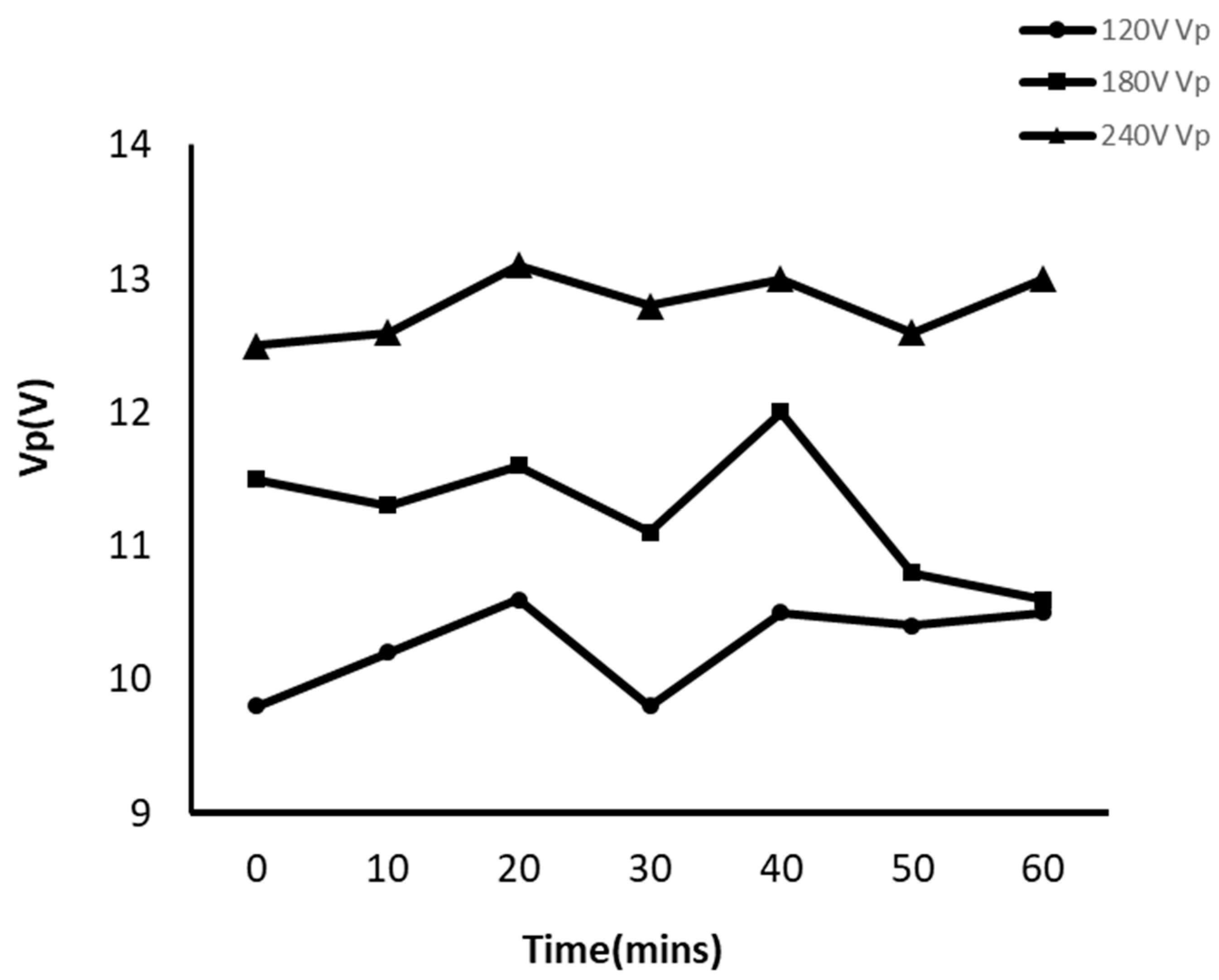
Figure 4 shows the bearing peak voltages instantaneously recorded at each 10 min. When the power supply setting was 120 V or 180 V, the bearing peak voltage (Vp) fluctuated significantly around 10.5 V or 11.5 V. However, for the 240 V case, the Vp remained high (~13 V). The Vp voltages increased with the power supply voltages. The high VP would cause more damage.

Figure 4.
The peak voltage (Vp) vs. time for different voltage Vsup settings.
Following oscilloscope measurements, the bearings were disassembled and examined under an optical microscope to observe macroscopic damage patterns. Figure 5 presents optical microscope images of bearing surfaces at different voltage levels. At 120 V (Figure 5a,d), the bearing surface showed minimal discoloration with no significant markings or alterations along the rolling paths. At 180 V (Figure 5b,e), moderate discoloration appeared along the rolling paths, characterized by light black streaks in the direction of ball movement, indicating localized areas of increased electrical activity. At 240 V (Figure 5c,f), continuous black markings were observed along the rolling paths, with a significantly darker appearance than the 180 V bearing, suggesting sustained high-voltage stress and surface degradation.
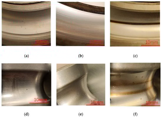
Figure 5.
Optical microscopy observations: (a–c) the outer rings and (d–f) the inner ring at (a,d) 120 V, (b,e) 180 V, and (c,f) 240 V tests, respectively.
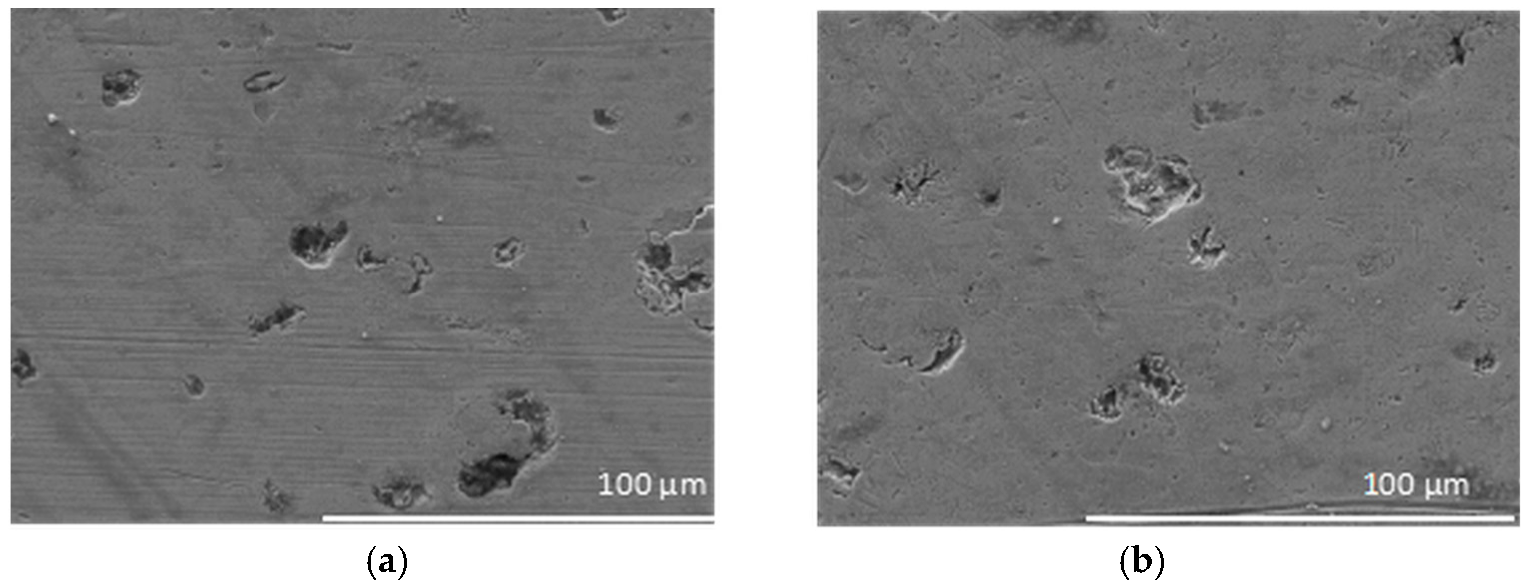
To further analyze the damage, SEM imaging was conducted on bearings tested at 180 V (Figure 6a) and 240 V (Figure 6b). The 180 V bearing exhibited moderate pitting and surface irregularities along the rolling paths, with shallow pits indicating localized material displacement. In contrast, the 240 V bearing displayed extensive pitting and crater-like formations, with more profound and widespread pits suggesting significant surface breakdown due to a higher-voltage stress. The presence of crater-like features indicates localized heating and material erosion. Oscilloscope readings, optical microscopy, and SEM imaging consistently show that increasing the power supply voltage intensifies electrical stress on the bearing system. At 120 V, the shaft voltage remained relatively stable, and the bearing surfaces exhibited minimal wear. At 180 V, periodic voltage spikes were recorded, correlating with visible surface discoloration and moderate pitting along the rolling paths. At 240 V, increased voltage fluctuations and extensive pitting confirmed the progression of electrical damage with higher voltage levels.
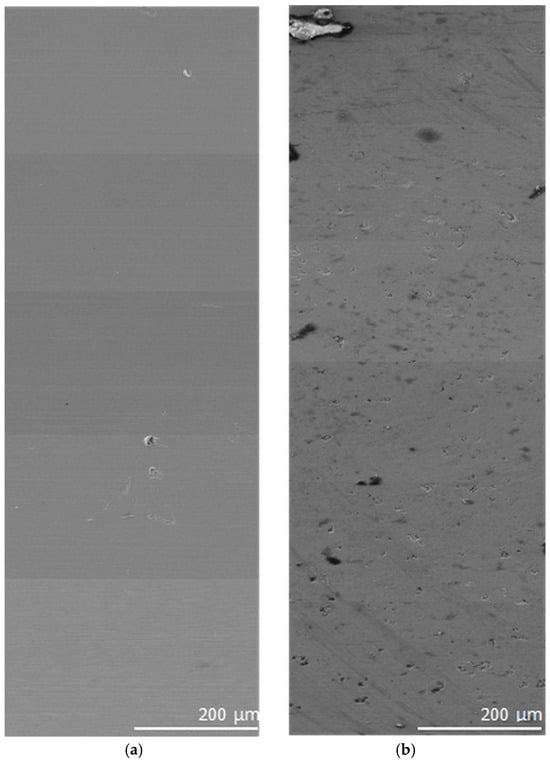
Figure 6.
SEM image for outer rings of bearings tested at (a) 180 V and (b) 240 V.
4. Analysis and Discussion
This study systematically investigated the effects of electrical currents and voltages on bearing damage under low-speed conditions, focusing on bipolar (120 V, 180 V, and 240 V) configurations. Through oscilloscope measurements, optical and SEM imaging, and compositional analysis, distinct patterns of electrical damage were observed, providing insights into the mechanisms and severity of bearing degradation in electrically charged environments.
4.1. Bipolar Voltage Effect
The bipolar experiments demonstrated a clear correlation between voltage levels and the severity of electrical damage to bearings. Oscilloscope data revealed that electrical stress intensified with increasing voltage, as reflected in the greater instability of waveforms at higher voltages. Bearings tested at 240 V exhibited the most pronounced disruptions, correlating with extensive surface damage observed post-experiment.
Microscopic analysis further confirmed this trend. Optical microscopy highlighted progressive discoloration along the rolling paths, with 240 V bearings showing continuous black markings indicative of localized material degradation. SEM imaging revealed that the 240 V bearings experienced significant surface pitting and crater-like formations, far more severe than those observed in 180 V bearings. During the tests, the bearing temperature was lower than 80 °C. The localized craters due to high-temperature melting are attributed to the electrical discharging effects. The results underline the critical impact of elevated voltage conditions in accelerating electrical wear, emphasizing voltage-limiting control’s importance in enhancing bearing reliability.
4.2. Electric Damage Analysis
This study’s characteristic pitting and crater-like damage occurred primarily at the contact areas between the outer ring, inner ring, and rolling elements (Figure 6 and Figure 7). Similar damage patterns have been reported in previous research [1], proving that the observed damage is directly caused by the electrical voltage and current applied during the experiments. The bearing damage would begin when an electrical current passes through the thin lubricant film separating the rolling elements and the raceways. Under the low-speed conditions of this study, the lubricant film was insufficiently thick to fully insulate the contact surfaces but allowed voltage to build up across the points of contact. When the voltage exceeded the breakdown threshold of the lubricant, an electrical discharge occurred. This discharge generated localized heat and pressure at the contact points, momentarily vaporizing the lubricant and melting small areas of the bearing material. After the discharge subsided, the molten material rapidly solidified, leaving behind pits or craters at the contact points.
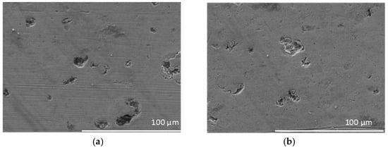
Figure 7.
SEM images of the raceway pitting after the 240 V test in (a) the vicinity of the direct ball contact path and (b) the direct ball-contacting areas.
Repeated discharges over time exacerbated this damage, leading to more bottomless pits and more pronounced cratering. The black markings observed along the rolling paths of the outer and inner rings were likely caused by chemical reactions between the grease and the bearing material, triggered by the localized heat from electrical discharges (Figure 5). These marks visually demonstrate the areas most affected by electrical stress and provide a direct indication of the electrical damage in different regions of the bearing. The observed damage was more severe in areas where the rolling elements made prolonged contact with the raceways [17,18], particularly under higher voltage conditions such as 240 V (Figure 7b). The increased voltage amplified the frequency and intensity of discharges, resulting in more extensive material degradation. This pattern aligns closely with prior findings [17], reinforcing the conclusion that electrical stress is the primary cause of the pitting and cratering observed in this study.
4.3. Black Markings Analysis
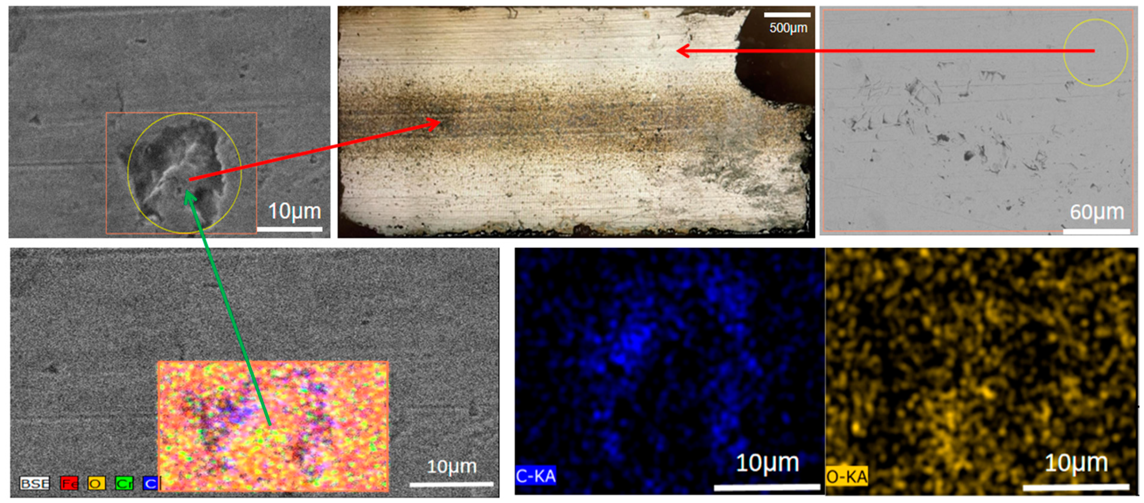
The black markings observed on the bearing surfaces, as shown in Figure 5 and Figure 8, provide compelling evidence of voltage-dependent electrical discharge effects within the bearing system. At lower voltages such as 10.5 V, these markings were faint or barely visible, while at 13 V, pronounced black streaks and bands became evident on both the inner and outer raceways. These visual indicators, concentrated near the rolling element contact paths, suggest a strong correlation between electrical activity and localized surface changes. Oscilloscope readings (Figure 3) reveal periodic voltage surges and sharp drops approximately every 10 cycles of the 10 kHz pulse current, indicating recurrent discharge events. These discharges are triggered when accumulated electrical energy within the bearing system reaches a critical threshold, leading to sudden releases that inflict localized surface damage.
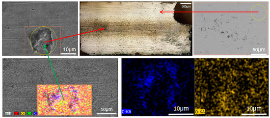
Figure 8.
EDS Analysis of the black marking.
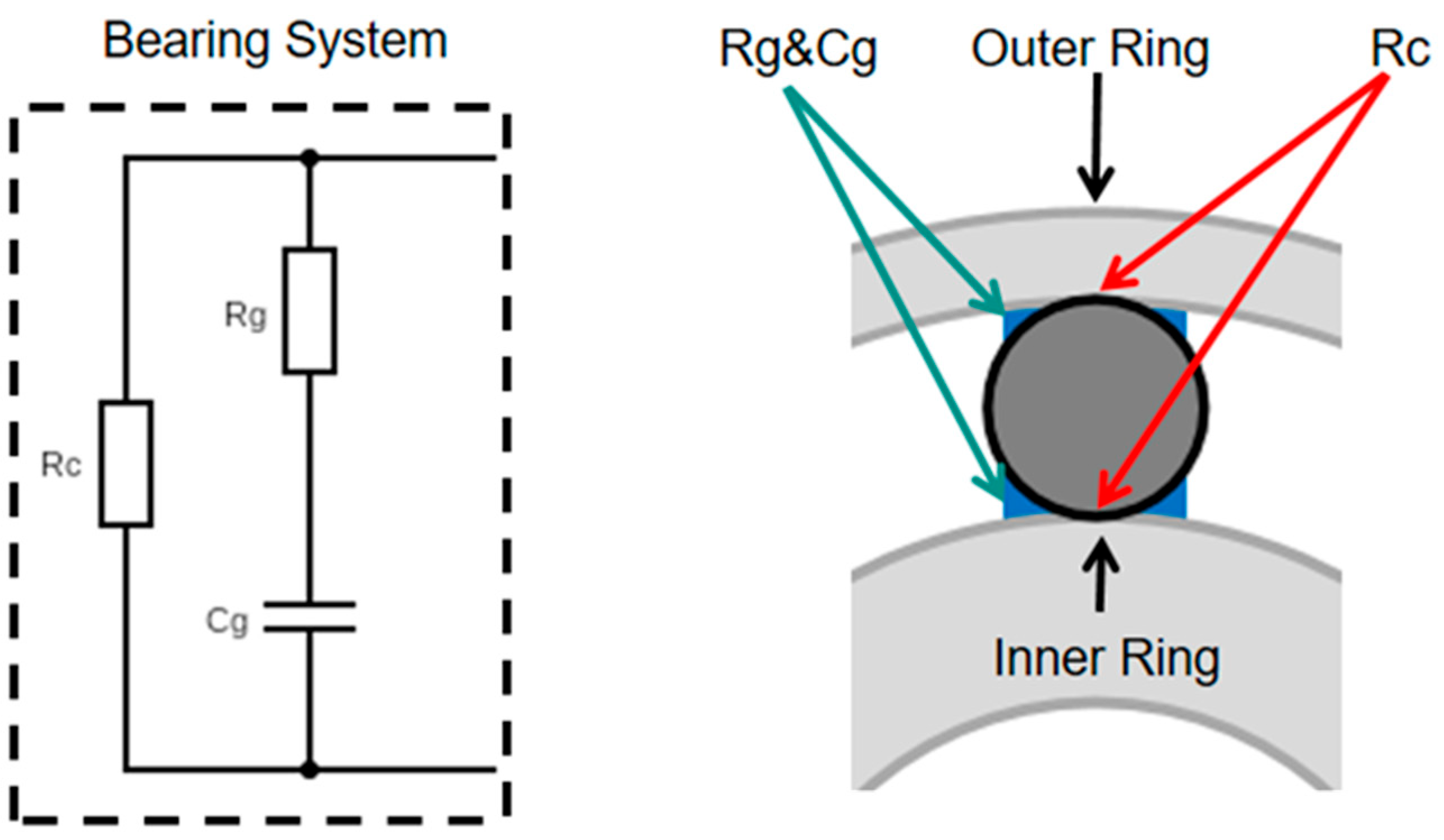
To explain this behavior, an equivalent circuit was proposed for the bearing system under low-speed operation (Figure 9), comprising contact resistance (Rc), grease resistance (Rg), and grease capacitance (Cg). Rc accounts for metal-to-metal asperity contacts during rotation, while Rg and Cg capture the conductive and dielectric behavior of the lubricating grease. Under repeated electrical cycling, the grease film, typically acting as an insulator, begins to accumulate charge. Once dielectric breakdown occurs, electrical discharges are initiated. The presence of Cg is supported by the recurring high-frequency spikes seen in the waveforms, which represent cycles of charge buildup and release. These findings are consistent with triboelectric principles and impedance-based analyses of lubricated bearings [8,18].

Figure 9.
Simple diagram of the bearing system.
Further analysis, especially SEM and Energy Dispersive Spectrometer (EDS) characterization in Figure 8, underscores the damaging effects of these discharges. SEM images reveal that the black-marked areas on the bearing surfaces exhibit crater-like features, in stark contrast to the adjacent clean regions, which remain smooth. EDS mapping within a cratered zone shows concentrated carbon (C) in the pits and a broader distribution of oxygen (O) around the edges. This spatial variation suggests that intense localized thermal events decomposed the grease, leading to carbon-rich deposits at the discharge centers and oxidation reactions at the peripheries. Quantitative data in Table 1 confirm this pattern, with significantly higher C and O concentrations in the black-marked areas compared to the clean regions.

Table 1.
Element weight (wt.) % of black and clean areas.
During loaded shaft voltage operation, particularly at 13 V, these thermal effects become more pronounced, resulting in grease overheating and chemical interactions with the metal surfaces [4,6,10]. This leads to the formation of visually distinct black bands without apparent alteration to the surface morphology, as seen in Figure 6a,b. The location and extent of these bands appear to be influenced by several factors, including grease film thickness, insulation properties, rotational speed, and bearing geometry. Although the black markings do not structurally damage the bearing surface, their presence highlights regions of high electrical stress. These observations confirm that electrical discharges are a key mechanism in bearing degradation [4], emphasizing the importance of managing grease properties and system insulation to mitigate such effects in practical applications.
4.4. Discussion
This study investigates electrically induced bearing damage using a pulsed bipolar power supply (10 kHz) applied to complete bearing assemblies under boundary lubrication conditions (30 RPM). The experimental setup enables real-time monitoring of electrical transients while characterizing subsequent mechanical damage through SEM and optical microscopy. Key findings include the identification of threshold discharge parameters (2.5 A/12 V) and the analysis of damage progression patterns under varying voltage conditions. While building upon foundational EIBD research, this work contributes new data on system-level bearing responses to high-frequency electrical stresses. The methodology uniquely integrates aspects of previous material-level testing with full bearing analysis under controlled low-speed scenarios relevant to electric vehicle operation. The results reveal measurable differences in damage morphology between low (10.5 V) and high (13 V) voltage inputs, with particular emphasis on understanding the formation mechanisms of characteristic black markings observed on raceway surfaces.
5. Conclusions
This study analyzes electrical discharge damage in bearings subjected to high-frequency pulsed voltages under low-speed rotating conditions. The relationship between shaft voltage fluctuations and electrical discharge-induced surface degradation was established by systematically investigating the effects of varying voltage levels. Oscilloscope measurements confirmed that when the applied power supply voltage increased, the shaft voltage exhibited significant instability, leading to frequent voltage that suddenly rises and then drops, indicative of discharge events. These discharges contributed to localized pitting and material loss on the bearing surface, with the severity of the damage escalating as the supply voltage increased. The 240 V tests, in particular, exhibited the highest shaft voltage fluctuations, corresponding to the most severe surface pitting and crater formation, as revealed by SEM imaging.
The black discoloration observed on the bearing raceways was linked to localized electrical discharge heating effects, which caused grease degradation and chemical interactions with the bearing material. Optical microscopy confirmed that higher voltage levels resulted in more pronounced and continuous black markings along the rolling paths, suggesting sustained electrical stress at the contact points between the rolling elements and raceways. SEM analysis showed that electrical pitting was concentrated at these rolling contact points, where the lubricant film’s charge accumulation and subsequent dielectric breakdown facilitated repeated discharge events. The observed damage patterns confirm that, under low-speed conditions, the rolling elements and their proximate grease films act as semi-conductive bridges that intermittently allow electrical currents to pass through, leading to a forceful localized surface breakdown.
The correlation between shaft voltage fluctuations, electrical discharge events, and tribological damage emphasizes the need for effective mitigation strategies in applications where bearings are exposed to high-frequency pulsed electrical powers. The findings indicate that electrical discharge damage became evident when the average current and peak voltage across the bearing reached 2.5 A and 12 V. To reduce the risk of electrical discharge wear, high-quality grounding for the motor shaft and frame is recommended to minimize current leakage through the bearing. In some cases, insulated bearings may also be required as an additional protective measure to prevent excessive electrical stress and prolong the bearing lifespan.
Author Contributions
Conceptualization, X.N.; methodology, Z.L.; software, R.C.; formal analysis, X.N. and Z.L.; writing—original draft preparation, Z.L.; writing—review and editing, Z.L., X.N. and R.C.; supervision, X.N. All authors have read and agreed to the published version of the manuscript.
Funding
This research received no external funding.
Data Availability Statement
The original contributions presented in this study are included in the article. Further inquiries can be directed to the corresponding author.
Acknowledgments
This research was supported by the Natural Sciences and Engineering Research Council of Canada.
Conflicts of Interest
The authors declare no conflicts of interest.
Abbreviations
The following abbreviations are used in this manuscript:
| Vsup | Voltage setting on the power supply |
| Asus | Current setting of the power supply |
| Vmul | Voltage which is measured by the multimeter |
| Vp | Peak voltage shown by the oscilloscope |
| Cg | Capacitance of grease |
| Rg | Resistance of grease |
| Rc | Resistance of the contact point between the rolling ball and the ring |
| SEM | Scanning electron microscopy |
| EV | Electric vehicle |
| DC | Direct current |
| AC | Alternating current |
| R (protector) | Resistance series with bearing to protect the system |
| C (system) | Capacitance of system |
| R (system) | Resistance of system |
| L (system) | Inductance of system |
| RPM | Revolution(s) per minute |
| EDS | Energy dispersive spectrometer |
| Fe | Iron |
| C | Carbon |
| Cr | Chromium |
| O | Oxygen |
| wt. | Weight |
References
- Janik, J.R.; Saha, S.; Jackson, R.L.; Mills, G. Exploring the Boundaries of Electrically Induced Bearing Damage in Grease-Lubricated Rolling Contacts. Lubricants 2024, 12, 268. [Google Scholar] [CrossRef]
- Guo, L.; Mol, H.; Nijdam, T.; de Vries, L.; Bongaerts, J. Study on the Electric Discharge Behaviour of a Single Contact in EV Motor Bearings. Tribol. Int. 2023, 187, 108743. [Google Scholar] [CrossRef]
- Peng, H.; Zhang, H.; Fan, Y.; Shangguan, L.; Yang, Y. A Review of Research on Wind Turbine Bearings’ Failure Analysis and Fault Diagnosis. Lubricants 2023, 11, 14. [Google Scholar] [CrossRef]
- Farfan-Cabrera, L.I. Tribology of Electric Vehicles: A Review of Critical Components, Current State and Future Improvement Trends. Tribol. Int. 2019, 138, 473–486. [Google Scholar] [CrossRef]
- Bleger, A.; Leighton, M.; Morris, N. Automotive E-Motor Bearing Electrical Discharge Phenomena: An Experimental and Numerical Investigation. Tribol. Int. 2024, 191, 109140. [Google Scholar] [CrossRef]
- Schneider, V.; Behrendt, C.; Höltje, P.; Cornel, D.; Becker-Dombrowsky, F.M.; Puchtler, S.; Gutiérrez Guzmán, F.; Ponick, B.; Jacobs, G.; Kirchner, E. Electrical Bearing Damage, a Problem in the Nano- and Macro-Range. Lubricants 2022, 10, 194. [Google Scholar] [CrossRef]
- Ma, J.; Xue, Y.; Han, Q.; Li, X.; Yu, C. Motor Bearing Damage Induced by Bearing Current: A Review. Machines 2022, 10, 1167. [Google Scholar] [CrossRef]
- Ye, H.; Yin, J.; Wang, X.; Lou, W.; Liang, P.; Liu, H. Electrical Fluting Damage of Rolling Element Bearings: Influences of AC Electrical Parameters and Operating Conditions. Tribol. Int. 2025, 208, 110658. [Google Scholar] [CrossRef]
- Gonda, A.; Capan, R.; Bechev, D.; Sauer, B. The Influence of Lubricant Conductivity on Bearing Currents in the Case of Rolling Bearing Greases. Lubricants 2019, 7, 108. [Google Scholar] [CrossRef]
- Hadden, T.; Jiang, J.W.; Bilgin, B.; Yang, Y.; Sathyan, A.; Dadkhah, H.; Emadi, A. A Review of Shaft Voltages and Bearing Currents in EV and HEV Motors. In Proceedings of the IECON 2016—42nd Annual Conference of the IEEE Industrial Electronics Society, Florence, Italy, 24–27 October 2016; pp. 1578–1583. [Google Scholar]
- He, F.; Xie, G.; Luo, J. Electrical Bearing Failures in Electric Vehicles. Friction 2020, 8, 4–28. [Google Scholar] [CrossRef]
- Huan, J.; Li, S.; Xia, Z.; Wang, Y.; Wang, W.; Shi, G. Experimental Study on Electric Corrosion Damage of Bearing and Solution. Proc. Inst. Mech. Eng. Part C J. Mech. Eng. Sci. 2022, 236, 10349–10358. [Google Scholar] [CrossRef]
- Kim, D.-H.; Kim, D.-W. Evaluation of Electrical Damage to Electric-Vehicle Bearings under Actual Operating Conditions. J. Korean Soc. Precis. Eng. 2023, 40, 45–52. [Google Scholar]
- Zhang, Y.; Li, X.; Wang, J. Electric Damage of Bearing under AC Shaft Voltage at Different Rotation Speeds. J. Mech. Eng. Res. 2024, 12, 45–53. [Google Scholar]
- Tawfiq, K.B.; Güleç, M.; Sergeant, P. Bearing Current and Shaft Voltage in Electrical Machines: A Comprehensive Research Review. Machines 2023, 11, 550. [Google Scholar] [CrossRef]
- Xu, Y.; Wang, Z.; Li, C.; He, J. Common-Mode Voltage Reduction and Fault-Tolerant Operation of Four-Leg CSI-Fed Motor Drives. IEEE Trans. Power Electron. 2021, 36, 8570–8574. [Google Scholar] [CrossRef]
- Zheng, J.; Xiang, D.; Li, H.; Quach, D.-C. An Investigation into the Effect of Bearing Grease Degradation on the High-frequency Bearing Current in an Inverter-fed Motor System. In Proceedings of the 2021 6th International Conference on Power and Renewable Energy (ICPRE), Shanghai, China, 17–20 September 2021; pp. 543–547. [Google Scholar]
- Park, J.-K.; Wellawatta, T.R.; Choi, S.-J.; Hur, J. Mitigation Method of the Shaft Voltage According to Parasitic Capacitance of the PMSM. IEEE Trans. Ind. Appl. 2017, 53, 4441–4449. [Google Scholar] [CrossRef]


Disclaimer/Publisher’s Note: The statements, opinions and data contained in all publications are solely those of the individual author(s) and contributor(s) and not of MDPI and/or the editor(s). MDPI and/or the editor(s) disclaim responsibility for any injury to people or property resulting from any ideas, methods, instructions or products referred to in the content. |
© 2025 by the authors. Licensee MDPI, Basel, Switzerland. This article is an open access article distributed under the terms and conditions of the Creative Commons Attribution (CC BY) license (https://creativecommons.org/licenses/by/4.0/).