Article

Wear Characteristics and Optimization Measures of Disc Cutters During Large-Diameter Slurry Tunnel Boring Machine Advancing in Soil-Rock Composite Strata: A Case Study

1
Key Laboratory of Urban Underground Engineering of Ministry of Education, Beijing Jiaotong University, Beijing 100044, China
2
School of Civil Engineering, Beijing Jiaotong University, Beijing 100044, China
3
CCCC Tunnel Engineering Bureau Co., Ltd., Beijing 100088, China
*
Author to whom correspondence should be addressed.
Lubricants 2025, 13(4), 170; https://doi.org/10.3390/lubricants13040170
Submission received: 5 March 2025 / Revised: 3 April 2025 / Accepted: 7 April 2025 / Published: 8 April 2025
(This article belongs to the Special Issue Recent Advances in Tribological Properties of Machine Tools)

Abstract

:
The large-diameter slurry tunnel boring machine (TBM) is widely used in the construction of tunnels across rivers and seas. However, cutter wear has become a critical issue that severely limits the tunnelling efficiency. Taking the Qingdao Jiaozhou Bay Second Subsea Tunnel Project as the background, the wear patterns of disc cutters on the atmospheric cutterhead of a large-diameter slurry TBM under complex geological conditions were analyzed. The flat wear of disc cutters induced by factors such as rock chip accumulation in front of the cutterhead, the jump trajectory when changing disc cutters, alloy-insert disc cutter mismatch, cutter barrel clogging, and severe wear of scrapers is discussed. Furthermore, the impacts of measures such as slurry circulation to remove rock chips during TBM stoppage, clay dispersant injection into the slurry chamber, cutter barrel flushing, and the wear resistance optimization of cutters and cutter barrels on reducing cutter wear were investigated. Based on numerical simulations and field data, a methodology for determining the optimal timing for cutter replacement is proposed. The results indicate the following: The circulation system effectively reduces accumulation, minimizing secondary wear of the disc cutters and lowering the risk of clogging in the cutter barrel. Adopting measures such as shield shutdown, a circulation system to carry away the slag, cutter barrel flushing, and soaking in 2% dispersant for 8 h can effectively reduce the accumulation of rock chips and mud cakes on the cutterhead, which in turn reduces the flat wear of the disc cutter. Measures such as making the cutter body and cutter ring rotate together and adding wear-resistant plates to the cutter barrel greatly improve the life of the cutter. The sharp increase in composite parameters can serve as an effective marker for assessing cutter conditions. The findings of this study can provide valuable insights into reducing cutter wear in similar projects.

1. Introduction

Large-diameter slurry shields have been widely used in the construction of undersea and cross-river tunnels [1,2,3]. Disc cutter wear is one of the important factors that seriously restrict the efficiency of shield tunnelling. Disc cutter wear can be divided into normal wear (uniform wear) and abnormal wear (fracture of the cutter ring, flat wear, cutter ring wear sharpening, etc.). In a TBM tunnel project in Shenzhen, with a total length of 1592 m, as many as 871 disc cutters have been replaced due to excessive uniform wear [4]. In a shield tunnel in the Guangzhou metro, a large number of disc cutter rings have been fractured due to shield tunnelling in composite strata. During the construction of Hangzhou Metro Line 3, disc cutters generally failed due to flat wear.
Many researchers have conducted in-depth investigations on disc cutter wear and cutting rocks with disc cutters. Cho et al. [5] established a three-dimensional rock-breaking model based on numerical simulation and presented the optimum spacing of disc cutters for eight different types of rocks. Duan et al. [6] investigated the influence of the geometric configuration on the rock-breaking behaviour while cutting rock with a disc cutter. Stopka [7] simulated rock cutting with asymmetrical disc-tools utilizing the discrete element method (DEM) and indicated that it is feasible to account for the complex kinematics of the rock-cutting process with disc-tools through DEM modelling. Lin et al. [8] conducted cutting tests for a constant-cross-section (CCS) disc cutter and inserted a tooth disc cutter to compare the rock-breaking characteristics between them. Agrawal [9] analyzed disc cutter wear under different geometric characteristics using DEM modelling. Gou and Zhang [10] evaluated the rock-cutting performance and contact behaviour of the proposed disc cutter design. Lu et al. [11] investigated the effects of the interaction between microwave energy and rocks on the performance of disc cutters on a TBM. Pan et al. [12] investigated the effect of confining stress on the rock-cutting efficiency of a TBM disc cutter using a full-scale linear cutting test. The problem of the flat wear and fracture of a disc cutter has also attracted extensive attention in engineering and academic circles [13,14], and the impact load of a disc cutter when it passes through the soft–hard interface of composite stratum is the focus of current research [15,16]. In view of the complexity and uncertainty of the fracture mechanism of the disc cutter ring, there are few related studies on it. Aghababaei and Zhao [17] comprehensively analyzed the matrix material, residual stress, mechanical properties, metal streamline, and micro-morphology of the fractured cutter ring according to the stress characteristics of the cutter ring, and determined the reason for fracture. Huang et al. [18] installed a strain sensor on the disc cutter base and developed a monitoring system for the real-time calculation of the rock-cutting force of the disc cutter. The monitoring results showed that the maximum normal force and lateral force peaks of the disc cutter appear every few seconds. The problem of eccentric tool wear is also widely relevant. Zhang [19] proposed that a reduction in rolling force was the direct cause of the flat wear of a disc cutter using the PFC3D method. Based on the RBD-DEM coupling method, Fang [20] investigated the sliding behaviour between a disc cutter and a rock, and indicated that this sliding behaviour can be reduced by increasing penetration.
In summary, while there has been extensive research on disc cutter wear, most studies have focused on normal wear patterns. However, there is limited analysis on the wear mechanisms of disc cutters in large-diameter slurry shield TBMs with atmospheric cutterheads under complex geological conditions, particularly regarding issues such as non-uniform wear induced by rock chip accumulation in front of the cutterhead and clogging of the cutter barrels, as well as the corresponding optimization measures. In this study, taking the Qingdao Jiaozhou Bay Second Subsea Tunnel Project as the background, the wear patterns of disc cutters on the atmospheric cutterhead of a large-diameter slurry TBM under complex geological conditions were analyzed. The flat wear of disc cutters induced by factors such as rock chip accumulation in front of the cutterhead, the jump trajectory when changing disc cutters, alloy-insert disc cutter mismatch, cutter barrel clogging, and severe wear of scrapers is discussed. Furthermore, the impacts of measures such as slurry circulation to remove rock chips during TBM stoppage, clay dispersant injection into the excavation chamber, cutter barrel flushing, and the wear resistance optimization of cutters and cutter barrels on reducing cutter wear were investigated. Based on numerical simulations and field data, a methodology for determining the optimal timing for cutter replacement is proposed.

2. Project Overview

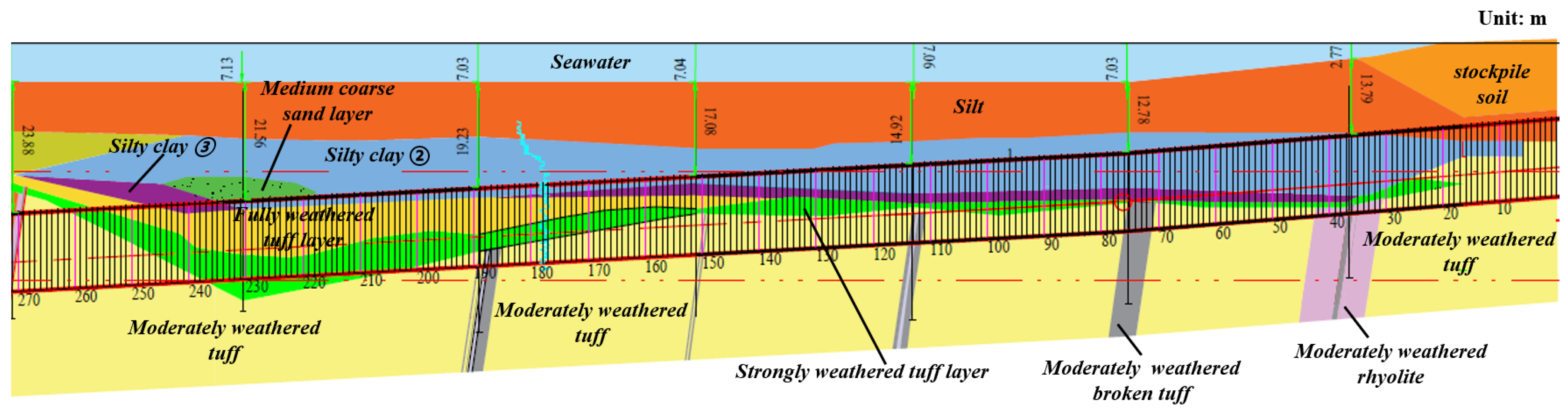
2.1. Engineering Geology

The Jiaozhou Bay Second Subsea Tunnel Project adopts a layout consisting of two-way six-lane main tunnels and a central service tunnel. The total length of the main route is 17.5 km, with the tunnel section spanning 14.36 km (9.95 km under the sea and 4.41 km on land). The maximum depth of the tunnel is 112 metres below sea level (approximately 969 metres for the shield tunnel section). The project employs a combined drilling–blasting and shield tunnelling method, with a construction period of 72 months. The shield tunnel of the main line employs a slurry TBM with an excavation diameter of 15.6m, and the shield starts from the Qingdao start shaft, tunnelling into the sea, and completing its course in the submarine dismantling chamber.
The surrounding rocks of the shield section are mainly class V, and partly classes IV and VI. The rocks within the shield tunnelling range are mainly divided into three main types: soil–rock composite strata (542 m); tuff strata, mainly hard rock strata (2645 m); and granite strata (72 m). The overburden depth of the arch is 12.82~69.63 m, and the highest water pressure of the tunnel is about 9.6 MPa. During tunnelling, the slurry TBM crosses a number of fracture zones, and the surrounding rocks of the fracture zones and their influence areas have poor stability, with many joints and fissures and a large amount of water. The quartz content of tuff is about 25%, and that of granite is about 45%. The rock mass strength varies greatly in the excavation interval. Geological exploratory holes reveal that the strength of the rock mass in the fractured zone averages 24 MPa and peaks at 84 MPa, while the strength of the intact rock mass averages 51 MPa and peaks at 146 MPa. The main section involved in this study was the 0~270 ring composite stratum, the lithology of which is presented in Figure 1.

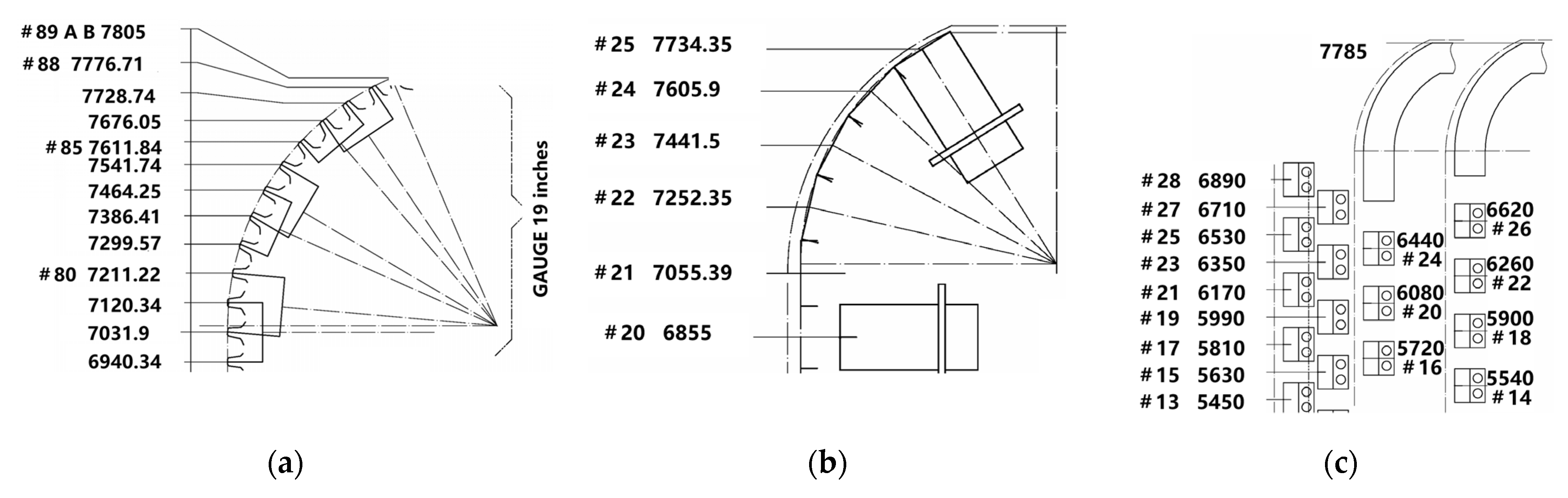
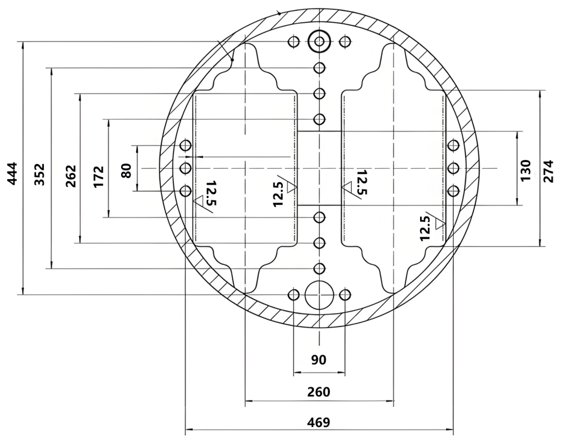
2.2. Cutter Configuration and Main Parameters of Slurry TBM

Considering that the complex and changeable highly abrasive stratum causes great damage to the cutters, the project employs an atmospheric cutterhead with a 30% opening rate. Compared with that of conventional cutterheads, the spatial arrangement of the atmospheric cutterhead is more restrictive, and fewer cutters can be installed. In this project, the minimum cutter spacing is set to 80 mm and the total number of cutters is up to 90, including 12 centre cutters (1~12 tracks), 64 front face cutters (13~76 tracks), and 14 edge cutters (77~89a, 89b). It is also equipped with 50 atmospheric pressure replaceable scrapers and 124 welded scrapers, and the total structure of the cutterhead is presented in Figure 2.
Considering a large range of clay in the shield tunnelling interval, in order to realize the unity and coordination of the rock-breaking and slag-scraping abilities and protect the cutterhead as much as possible, the design concept of a layered cutter configuration was applied in this project. The first layer of the atmospheric pressure replaceable disc cutter was designed to break the rock, and the height of the cutter was set to 225 mm. The second layer of the atmospheric pressure replaceable scraper was designed to scrape slag, and the height of the scraper was set to 205 mm. The third layer of the welded scraper was designed to protect the cutterhead, and the height of the cutter was set to 165 mm. The typical position of the cutter trajectory layout is shown in Figure 3.
The disc cutter is the 17-inch constant-cross-section cutter made by Herrenknecht, Germany, with the dimensions shown in Figure 4. The longitudinal layout of the three types of cutters in space is shown in Figure 5. From the perspective of the layered cutter configuration, when the disc cutter wear has not exceeded the limit, the scraper only serves to remove slag. When the disc cutter wear exceeds the limit, the scraper participates in rock breaking and also helps to protect the cutterhead.
The main machine length of the slurry TBM is 15.81 m, the maximum tunnelling speed is 50 mm/min, and the maximum cutter speed is 1.74 rpm. The torque and thrust adjustment ranges are 0~42,968 kN·m and 0~287,056 kN, respectively, which can be adapted to tunnelling under complex geological conditions. The detailed TBM design parameters are shown in Table 1.

3. Wear Characteristics and Patterns of Cutters on Large-Diameter Atmospheric Cutterhead

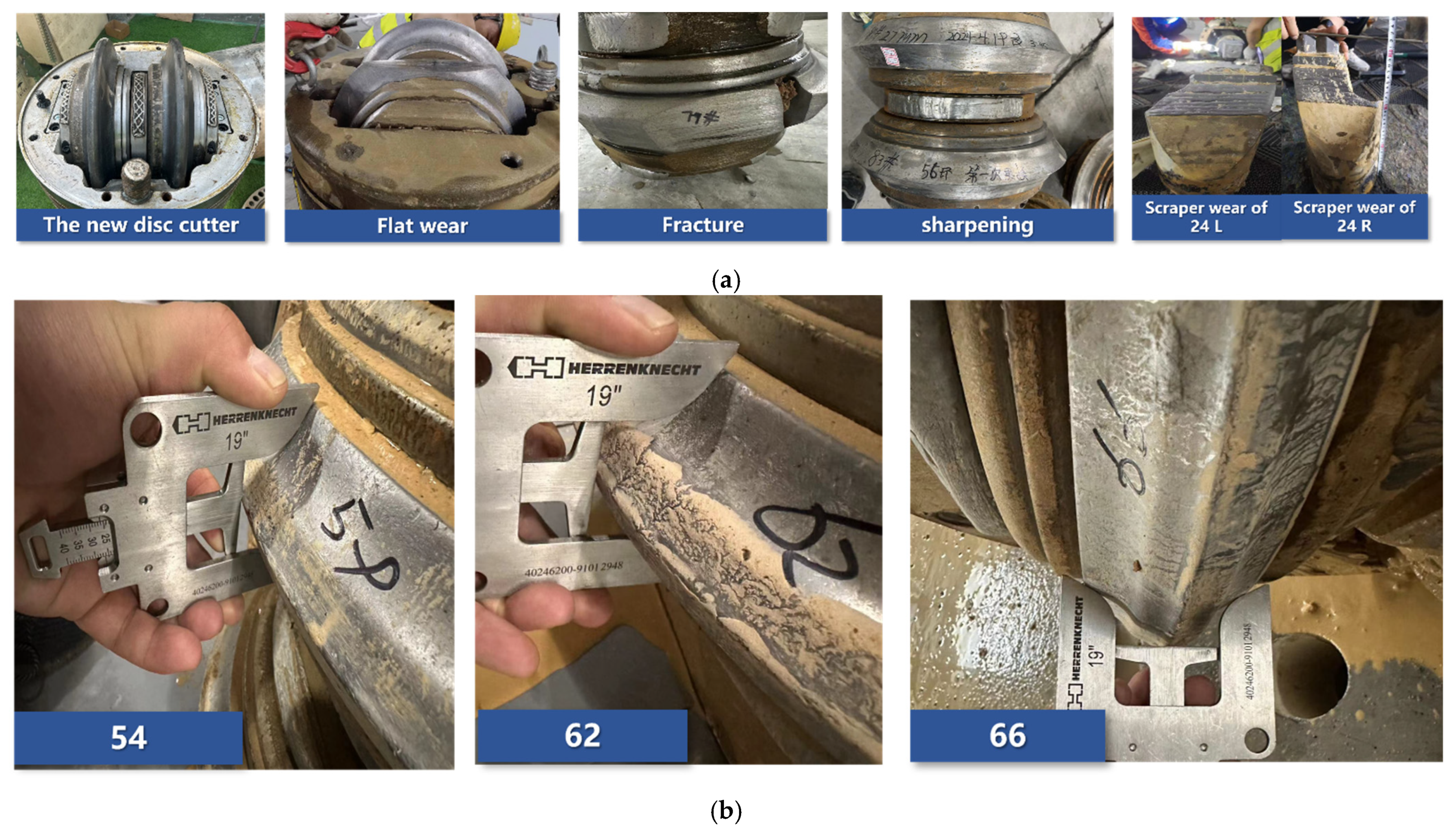
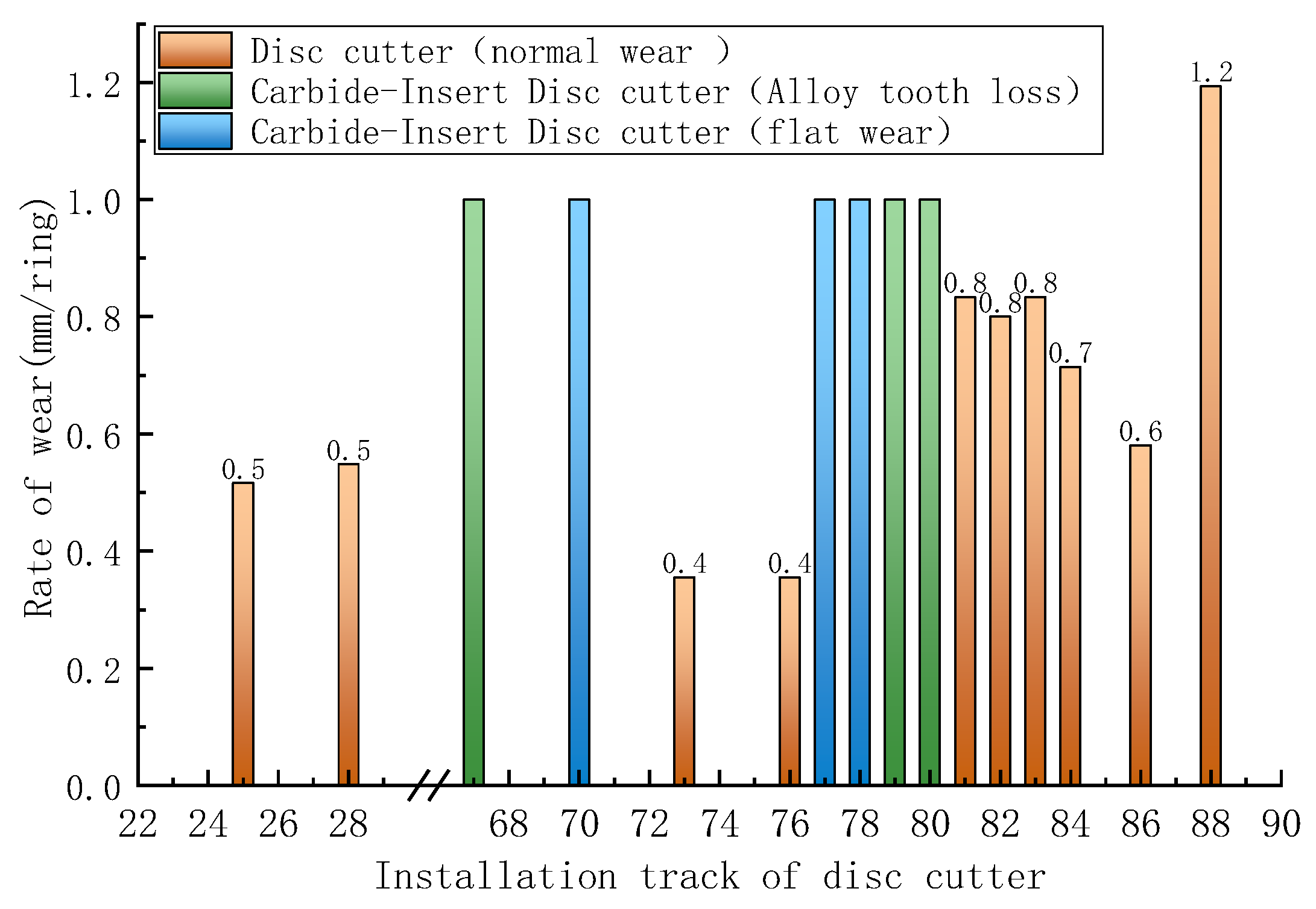
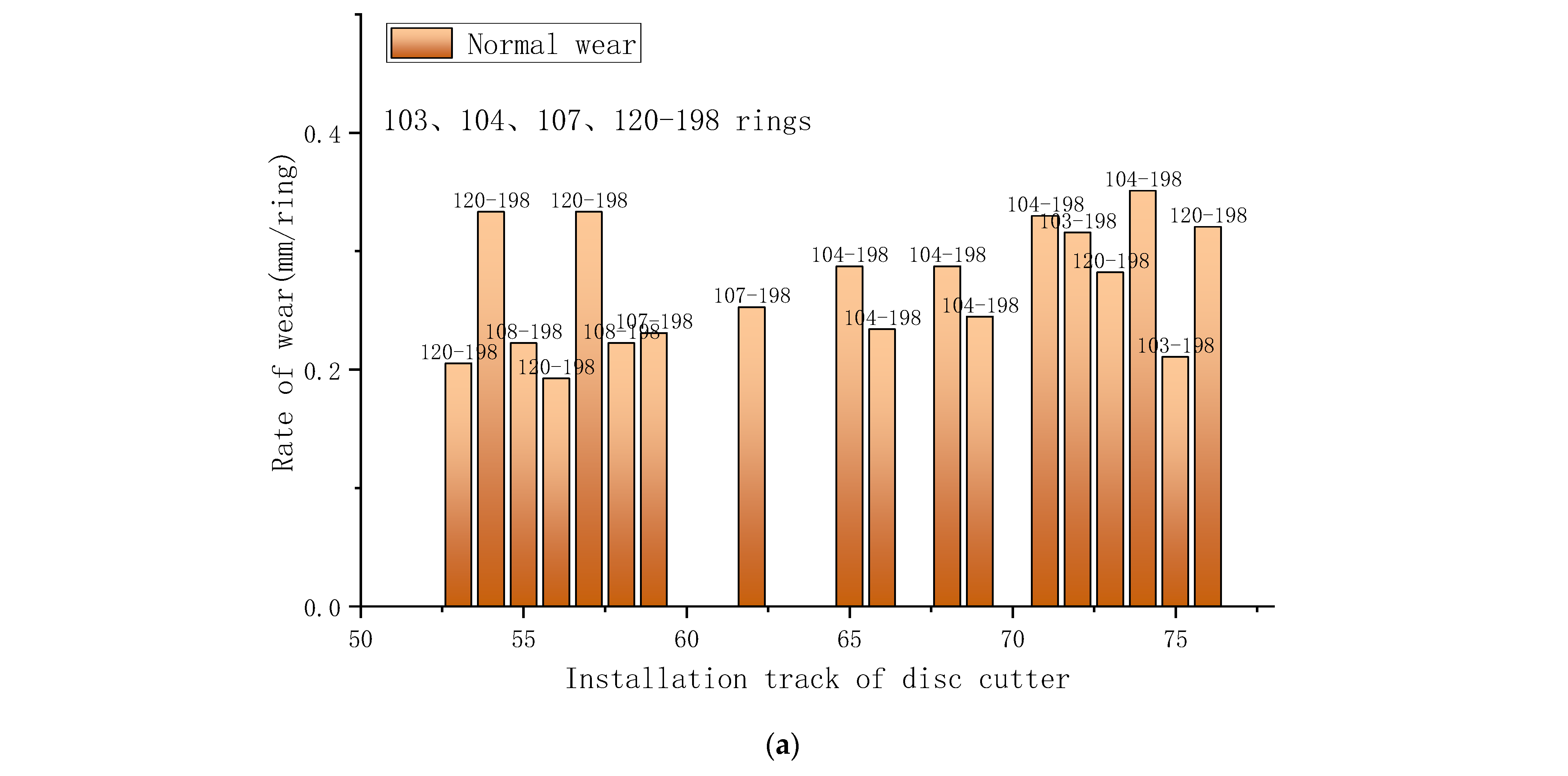
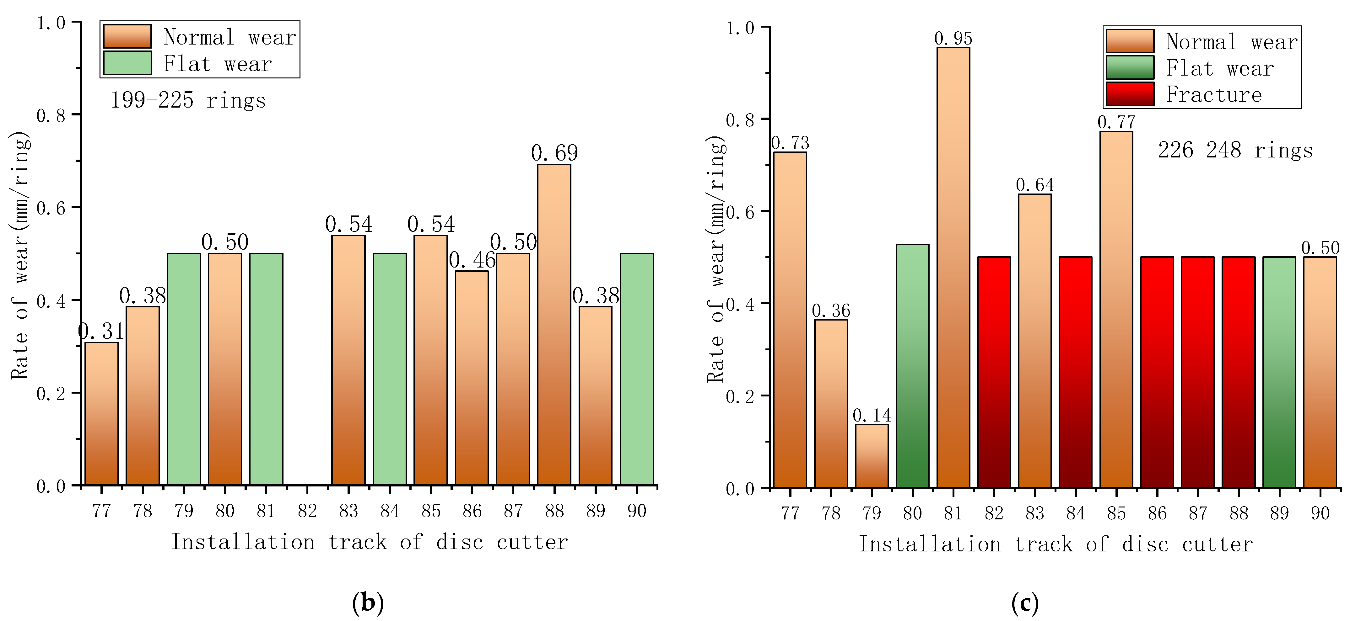
3.1. Analysis of Disc Cutter Wear Patterns

In practical engineering, a significant number of worn cutters have been replaced. The main failure modes of the cutters are shown in Figure 6 and can be categorized into four types: normal wear, flat wear, fracture, and cutter ring sharpening. As illustrated in Figure 6, when the disc cutter undergoes normal wear, the wear is uniformly distributed along the circle of the cutter ring. Flat wear means that the disc cutter’s rotation stops and the wear is concentrated in a localized position on the cutter ring. The fracture of the cutter ring is well understood; it is an instantaneous fracture of the metal cutter ring caused by excessive rock-breaking loads. Cutter ring sharpening mainly refers to a change in the geometry of the cutter ring that makes it sharper. Notably, the cutter rings of the disc cutters in the edge areas of trajectories 78 to 86 exhibit significant secondary wear characteristics, manifested as accelerated wear and sharpening of the cutter rings. This indicates the presence of a certain degree of rock chip accumulation in front of the atmospheric cutterhead, causing secondary wear on the cutters. For the front face cutter, the failure is mainly manifested in the form of localized sharpening of the cutter ring, which is due to the softer stratum and greater penetration. Additionally, there is no overall sharpening of the cutter ring in this area, which indicates that the cutter in this area is less affected by the secondary wear of rock chip accumulation. In the specific case of the layered configuration of scrapers and disc cutters, the scraping effect of the scraper helps to reduce the accumulation of rock chips on the front of the cutterhead and reduce the secondary wear of the disc cutter. When the wear of the disc cutters exceeds the allowable limit, the scrapers on the corresponding trajectories are forced to directly cut the excavation face, which leads to the rapid wear and failure of the scrapers, significantly reducing their ability to remove rock chips. As a result, the accumulation of rock chips becomes severe, further exacerbating the wear on both the scrapers and disc cutters.
Unlike the pressurized cutterhead, it is not possible to directly observe the wear of each cutter during normal pressure tool change. Therefore, in actual engineering practice, the decision on which cutters to replace needs to be based on experience and analysis in batches. When the shield tunnelling reached the 56th ring, the cutters in the edge area were replaced in a focused manner. The wear rate is shown in Figure 7. The wear rate of the edge cutters exhibited a significant surge, which corresponds to the observed phenomenon of the cutter rings at the edges becoming sharp. The accumulation of rock chip in front of the cutterhead exacerbated the cutter wear rate, which increased from 0.27 mm/ring to 0.37 mm/ring from trajectory No. 77 to trajectory No. 78, and it is deduced that the height of the rock chip in front of the cutterhead was approximately that of disc cutter No. 78. For the edge disc cutter, despite the gradual increase in its installation radius, the wear rate showed a gradual decay, which was the result of the gradual decrease in the cutter spacing.

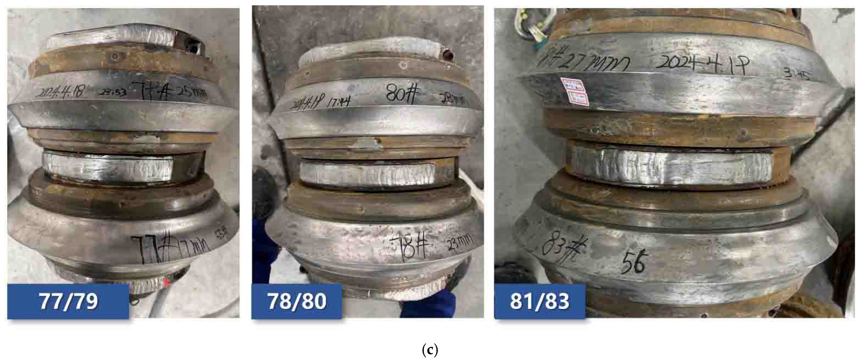
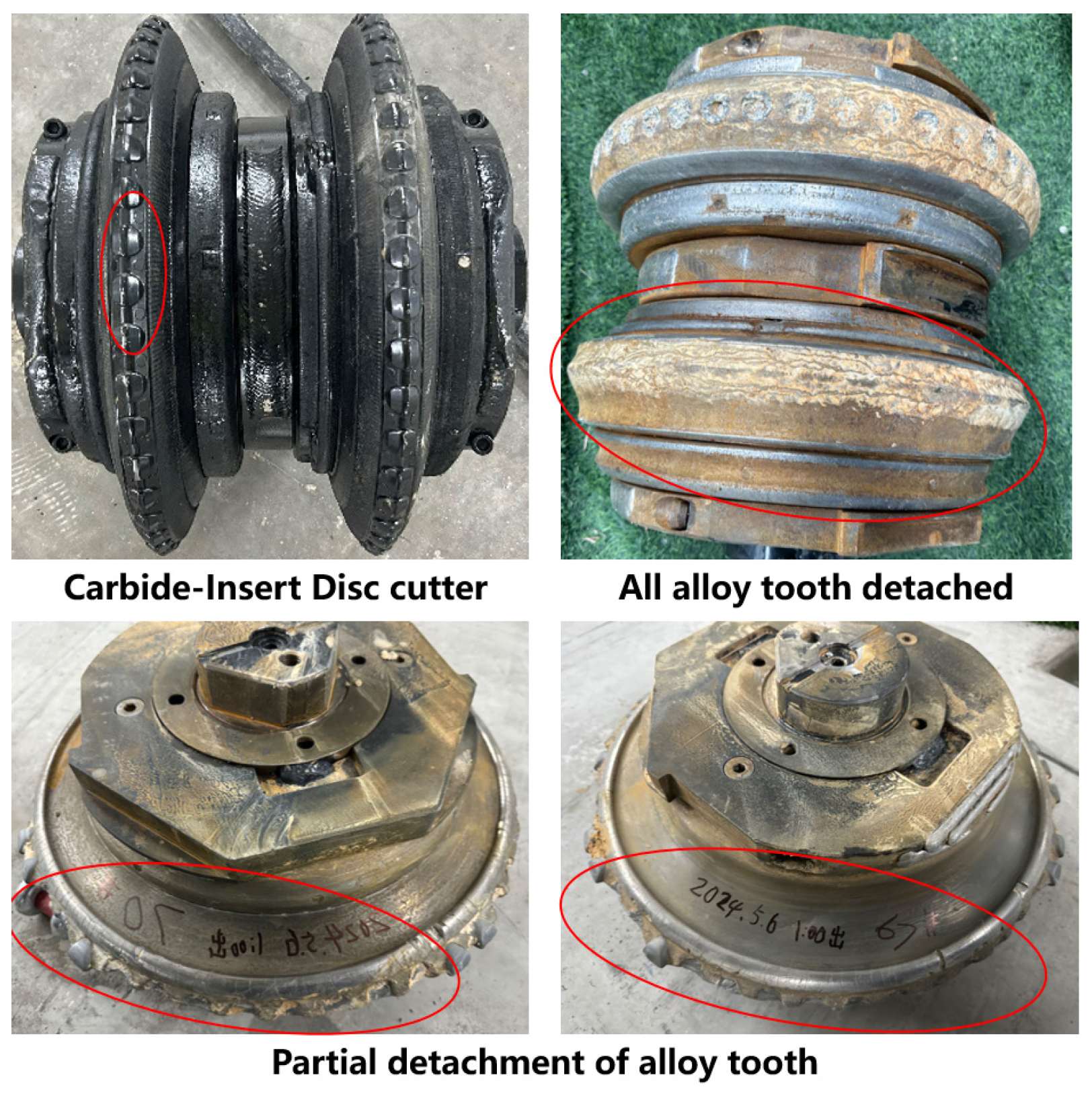
3.2. Mismatch Between the Stratum and the Alloy-Insert Disc Cutter

In the tunnelling interval from ring 57 to ring 98, tests were conducted on different types of disc cutter. The results are shown in Figure 8; the disc cutters with alloy teeth detached and flat wear were replaced at ring 87, while the rest of the disc cutters were replaced at ring 98. As shown in Figure 8, the disc cutters generally showed normal wear, whereas the alloy-insert disc cutters exhibited significant flat wear and fracture. The failure of the alloy-insert disc cutter can be attributed to two reasons: Firstly, the accumulation of rock chips in front of the cutterhead led to serious wear on the side of the cutter body, and the tooth bed of the alloy teeth was damaged to a certain extent. Secondly, the rock joints and fissures in this project were developed with uneven strength, and the impact load is greater in the process of rock breaking, which further leads to the alloy teeth falling off from the tooth bed and, finally, the cutter’s fracture or flat wear, as shown in Figure 9. In conclusion, due to the specific issue of rock chip accumulation in front of the cutterhead, the alloy-insert disc cutters were not suitable for this project.

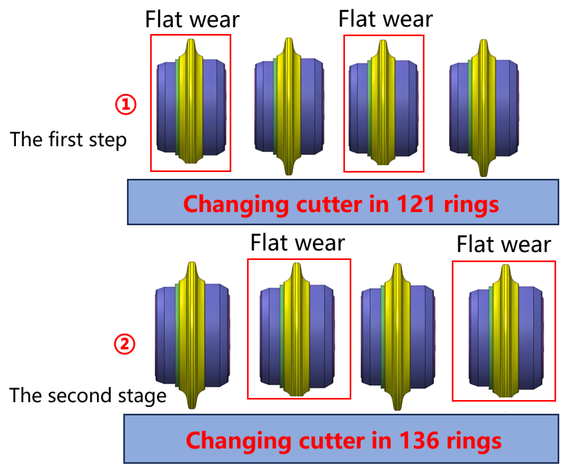
3.3. Flat Wear Induced by Trajectory Jumping for Cutter Replacement

The DCRM (disc cutter rotation monitoring) system is a crucial tool for evaluating the working condition of each cutter. Its operating principle involves monitoring the magnetic signals on the cutter ring and converting them into the sensor value. The sensor value is positively correlated with the rotation speed of the disc cutter. Figure 10 illustrates the working principle of the DCRM system. When the cutter is breaking rock normally, it rotates around the centre of the cutterhead at an angular velocity of ω1 and simultaneously rotates around the cutter shaft at an angular velocity of ω, realizing the rotational breaking of rock. When the state of the cutter is abnormal—for example, when there is flat wear or the cutter ring is fractured—its rotational angular velocity ω is certain to change and decrease to nearly 0. On the circumference of the cutting ring, there are eight magnets evenly distributed, and the magnetic signal sensor calculates the current rotational velocity ω of the cutter by detecting the change in the magnetic signal. The electromagnetic signal is processed by a series of noise reduction procedures, which is the core technology of the DCRM manufacturers and is not disclosed. As a result, the sensor values recorded in DCRM systems from different manufacturers are not the same, with some representing the rotational speed of the disc cutter and others representing the number of changes in the electromagnetic signal. Due to the confidentiality of Herrenknecht’s technology, it is not possible to know the detailed correspondence between the sensor value and the rotational speed of the disc cutter.
The theoretical rotational speed of the disc cutter under normal working conditions is calculated using the following formula:
ω 1 · R 1 = ω · R
where ω1 is the rotation speed of the cutterhead, R1 is the installation radius of the disc cutter, ω is the rotation speed of the disc cutter, and R is the radius of the disc cutter. For this project, the installation radius of disc cutter No.89 is the largest and R is 7805 mm (Figure 3); the rotational speed of the cutterhead is 1 r/min when the TBM is tunnelling normally; and the radius of the disc cutter is 241.5 mm, so its theoretical maximum rotational speed is 203 rad/min.
It is certain that the sensor value is positively correlated with the rotation speed of the cutter. The smaller the sensor value, the lower the rotation speed of the cutter ω. When the sensor value is close to 0, the disc cutter stops rotating and needs to be replaced.
Figure 11 displays the working interface of the DCRM system. After 121 rings, the rotation value of hob No. 87 was decreasing, and after 136 rings, it was in a completely low-rotation state, while the temperature increased from 30° to a maximum of 50°. The combination of a decreased rotation speed and increased temperature serves as a key indicator for identifying flat wear of the disc cutter. However, after identifying and replacing the abnormally worn disc cutter through the DCRM system, it was observed that the disc cutters on neighbouring tracks, which were not replaced, subsequently exhibited flat wear and failure.
There is a total of 1~89 tracks of disc cutters on the cutterhead for this project. In engineering practice, there are two strategies for replacing worn disc shape hobs: continuous trajectory cutter replacement and skip-track cutter replacement. Continuous trajectory cutter replacement means replacing all the cutters on consecutive trajectory numbers, for example, replacing all the cutters on trajectory numbers 70 to 74. Skip-track cutter replacement means skipping the slightly worn cutter tracks and replacing only the severely worn cutters, for example, replacing tracks 70, 72, and 74. During the tunnelling process from ring 104 to ring 136, flat wear was induced by skip-track cutter replacement. As shown in Figure 12, the cutters on tracks 84 and 86 were first replaced at ring 121. The direct reason for replacing these disc cutters was the detection of abnormal cutter conditions by the DCRM system at ring 121. Subsequently, the disc cutters on tracks 85 and 87 were used as the unreplaced cutters and continued tunnelling. Ultimately, all the cutters on tracks 84 to 87 exhibited flat wear in ring 136. Figure 13 reveals the mechanism by which skip-track cutter replacement induced the flat wear of disc cutters. In the first step, replacing the unevenly worn cutters resulted in the new cutters having a greater height than the adjacent cutters in the second stage. This led to the failure of multi-cutter cooperative rock breaking, causing the adjacent cutters to experience flat wear again. Therefore, in practical engineering, it is essential to ensure that the cutter replacement follows a continuous track as much as possible to avoid skip-track replacement.

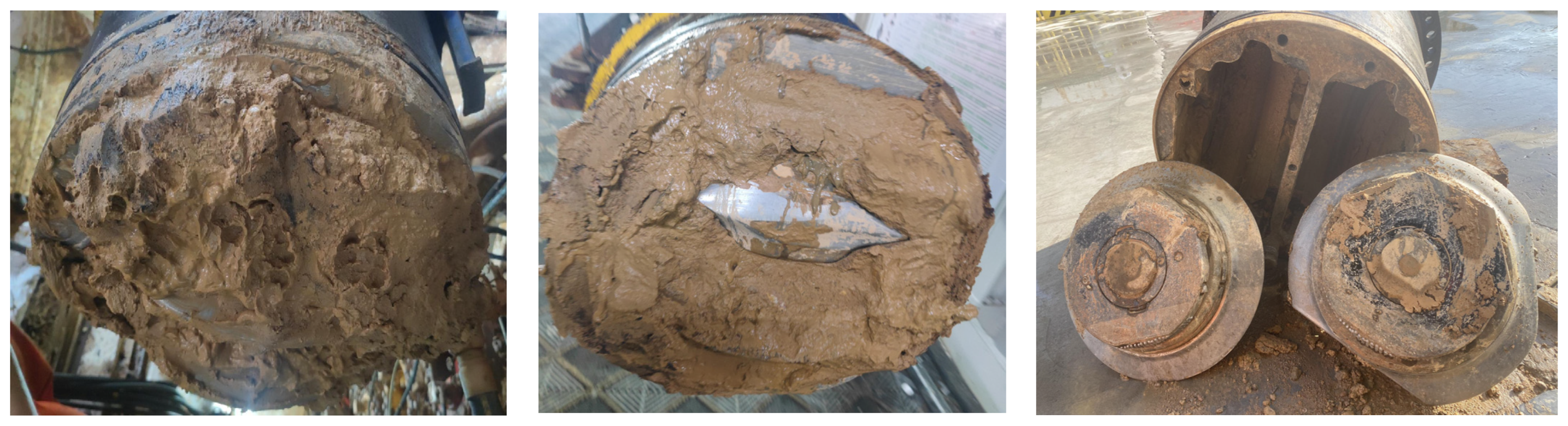
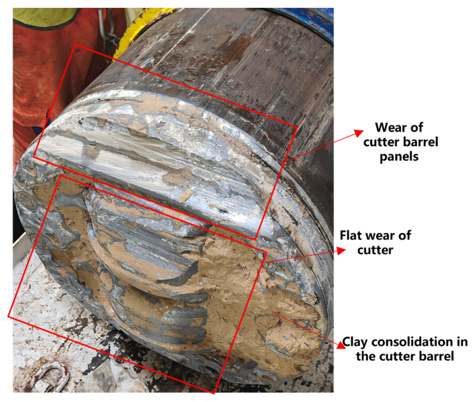
3.4. Cutter Barrel Clogging Induces Disc Cutter Flat Wear

Due to the special structural design of the cutter barrel, the clay from the stratum enters the barrel, leading to severe clogging. As shown in Figure 14, observations of the cutter barrel during atmospheric pressure cutter replacement revealed a significant accumulation of clay, which necessitated the use of high-pressure water jets to remove the clogged clay. At the same time, the friction heat and cutting heat caused the clay near the cutter to undergo some solidification, forming a mud cake. The clogging of the cutter barrel, coupled with the mud cake wrapped around the cutter, made it difficult for the disc cutter to rotate, which induced flat wear.
Because the height difference between the atmospheric scraper and the disc cutter is 20 mm, when the flat wear of the disc cutter reaches a certain limit, the scraper of the corresponding trajectory is involved in breaking the rock. The scraper is not suitable for cutting rock, so the wear rate is extremely fast. When the scraper wear seriously exceeds the limit, the cutter body and cutter barrel are in direct contact with the rock chips and the excavation face, generating a large amount of heat, and the consolidation of clay in the cutter barrel is further aggravated. More critically, both the cutter body and the cutter barrel experience severe wear (as shown in Figure 15), posing a high safety risk and causing substantial economic losses.

3.5. Extensive Abnormal Wear of Edge Disc Cutter

In the process of tunnelling, it was observed that the abnormal wear of the edge disc cutters seriously affected the slurry TBM tunnelling efficiency, while the front disc cutters were predominantly affected by normal wear. As presented in Figure 16, in rings 103~198, the wear of the front disc cutters was examined, and all showed normal wear, with the wear rate ranging from 0.15 to 0.35 mm/ring. In rings 199~225, the edge disc cutters were examined, and four were flat worn. The edge disc cutters were checked again at rings 226~248, and five were fractured while two were flat worn. The clogging of the cutter barrel, the accumulation of rock and clay particles in front of the cutterhead, and the high cutting speed led to serious abnormal wear of the edge disc cutters, and effective measures must be adopted to solve these problems.

4. Measures to Reduce Abnormal Cutter Wear

This section presents a series of measures taken to reduce abnormal cutter wear in detail, including circulation to carry away rock chips during shield stoppages, cutter barrel flushing, clay dispersant soak slurry chambers, and the optimization of cutter barrel wear resistance.

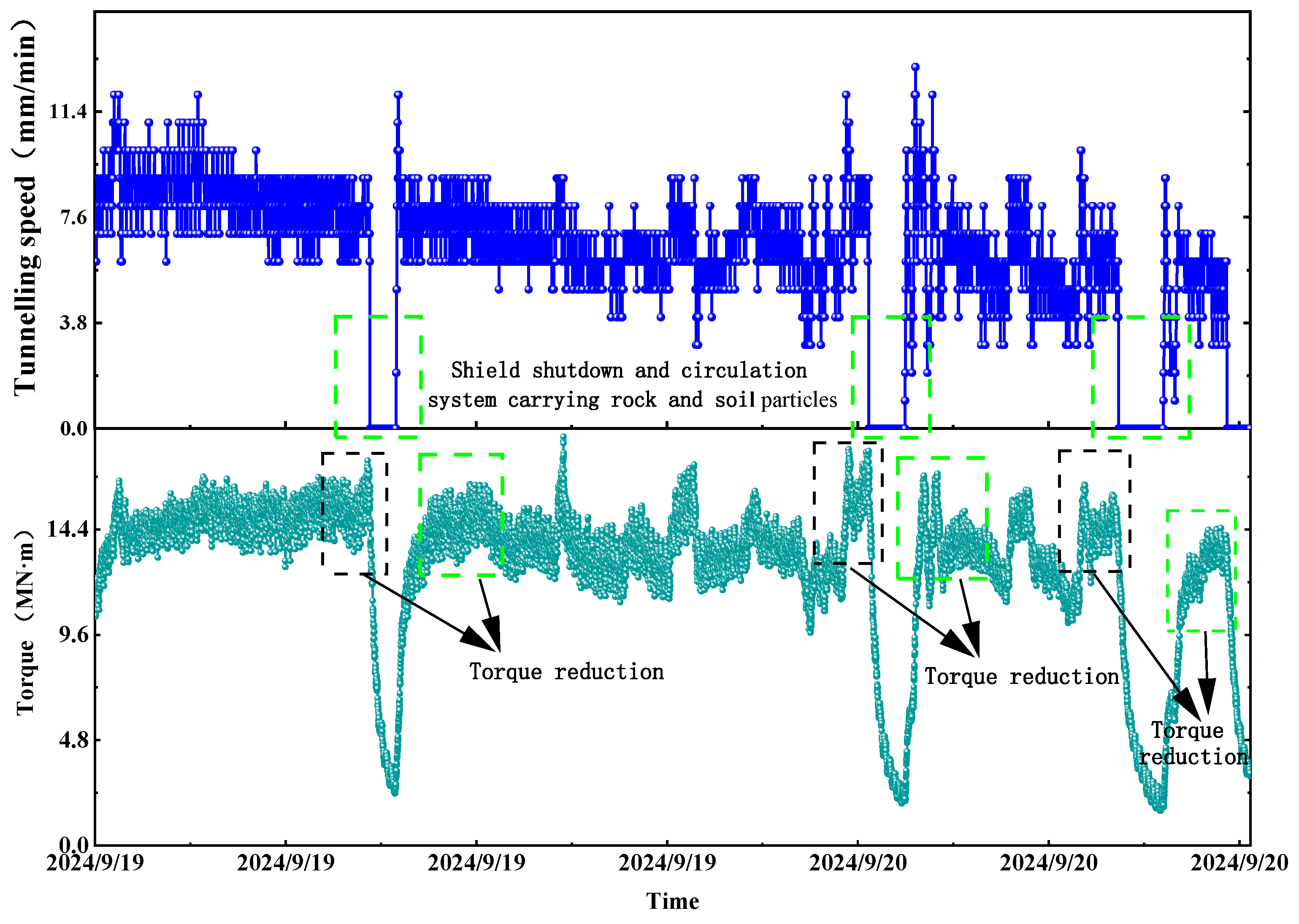
4.1. Enhancement of Circulation Carry Rock and Soil Particles During Tunnelling Process

During the tunnelling process, slurry pumps provide power to transport rock and clay particles from the excavation surface to the ground through slurry and pipes, and this process is referred to as slurry circulation. When the cutterhead torque exceeds 15 MN·m, it is necessary to halt the tunnelling and initiate circulating muck removal. The flow rate of the circulation system is 2900 m3/h, which is the maximum flow rate that the circulation system can provide, and it is expected that a higher flow rate can reduce the accumulation of rock and clay particles in front of the cutterhead. When the TBM stops, no new rock or clay particles are generated at the excavation face, so the particles accumulated in front of the cutterhead are gradually reduced by the slurry carrying them. The circulation system ensures that the excavated soil or rock particles are more efficiently transported out of the slurry chamber, reducing the chance of sedimentation and preventing particles from accumulating in front of the cutterhead. For example, as shown in Figure 17, during the tunnelling of ring 349, circulating muck removal was performed three times. Before the muck removal, the cutterhead torque reached 17.3 MN·m, 18 MN·m, and 15.9 MN·m, respectively, while the tunnelling speed remained at 8 mm/min. After the muck removal process was completed, the tunnelling speed increased to 11 mm/min, and the cutterhead torque decreased to 14.1 MN·m, 16.5 MN·m, and 12.2 MN·m, respectively. The circulation system effectively reduces the accumulation of rock chips in front of the cutterhead, minimizing secondary wear of the disc cutters and lowering the risk of clogging in the cutter barrel.

4.2. Increased Cutter Barrel Flushing

Because the slurry TBM flushes the centre of the cutterhead through a centrifugal pump, the flushing of the cutter barrel in the centre area is maintained uninterrupted during the tunnelling process, with a flow rate of 1000 m3/h. The front face and edge area cutter barrels do not have a flushing function; therefore, after the tunnelling of each ring is completed, the cutter barrels are flushed through the external pressurization of the shield, and the flushing pressure peaks at 1.6 MPa. It is found that, during the flushing process, some of the cutter barrel flushing passages are already clogged. Taking 339 rings as an example, a total of 18 cutter barrels were flushed, of which 9 were open and 9 were clogged. Therefore, in strata containing a lot of clay, the cutter barrel flushing passages should be checked to prevent further deterioration through clay clogging and the formation of mud cakes.

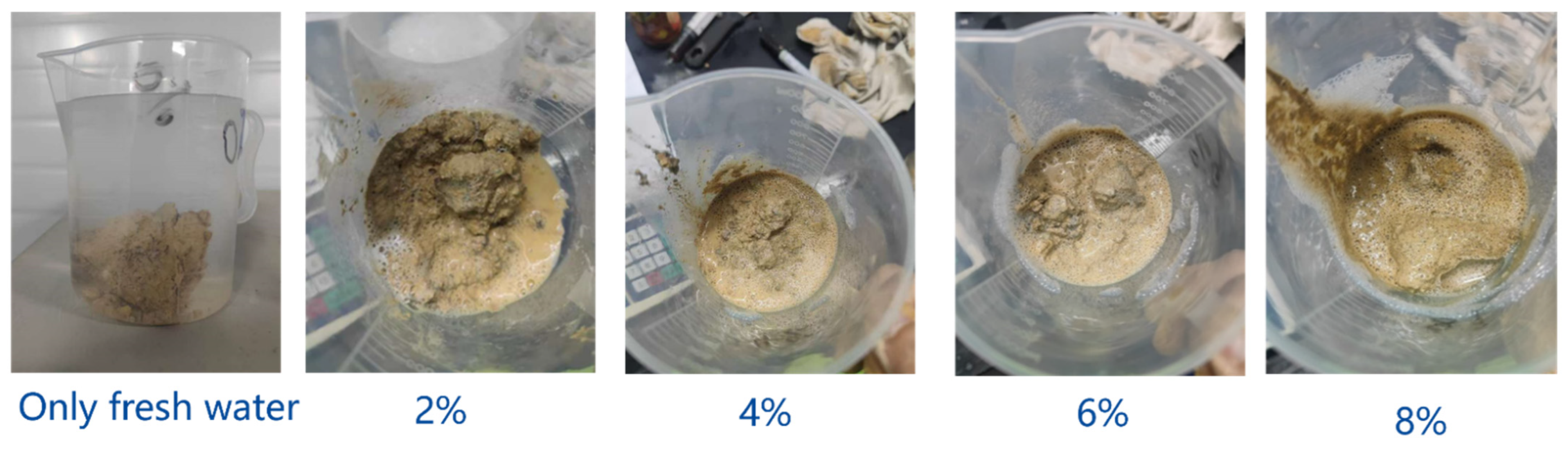
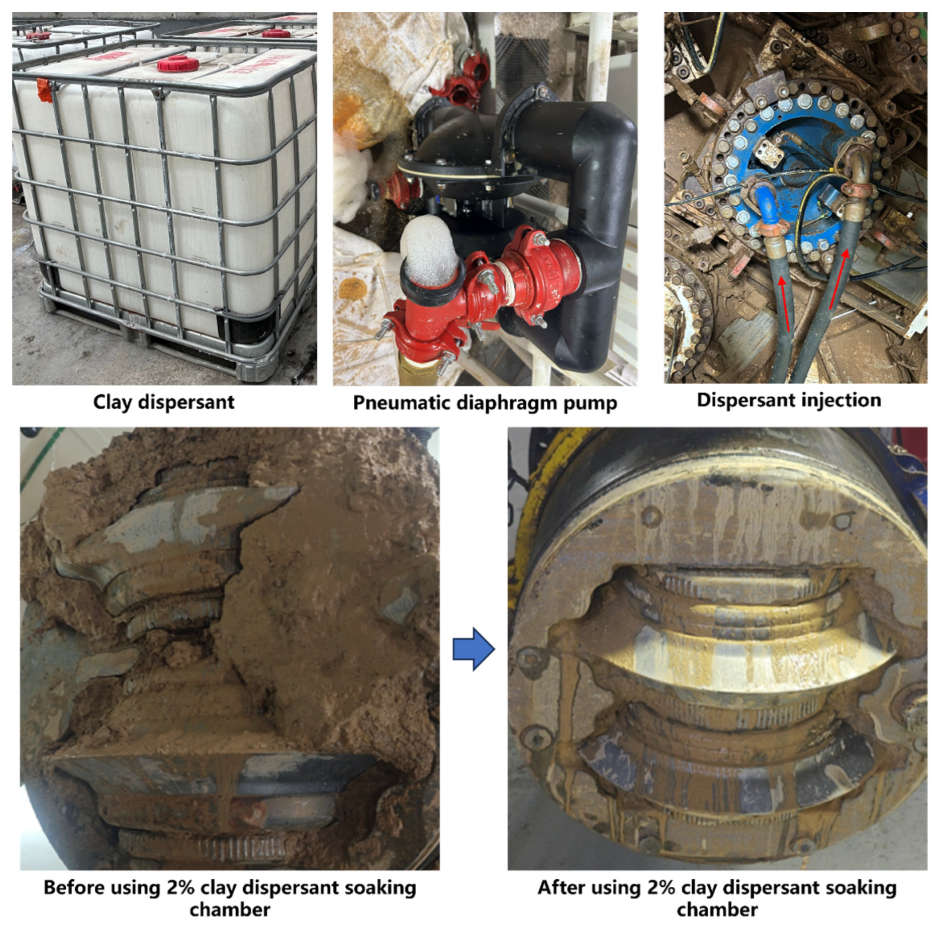
4.3. Clay Dispersant Soaking Chamber

When the clay clogging in the cutter barrel is more serious and mud cakes are formed, flushing can not prevent the accumulation of mud in the cutter barrel. This results in the disc cutter not being able to rotate and continued partial wear, and the slurry chamber must be soaked with clay dispersant. The dispersant effectively weakens interparticle bonds within clay structures, releasing bound water and reducing clay adhesiveness, thereby preventing mud cake formation in the cutter barrel. In this project, Yitongtong clay dispersion was employed; laboratory tests needed to be carried out to determine the optimal ratio of the dispersant before it was used.
Laboratory tests were conducted using 200 g clay samples immersed in dispersant solutions with concentrations of 0%, 2%, 4%, 6%, and 8% for 5 h (Figure 18). It is necessary to note that the mud cakes in the laboratory tests were taken from the cutter barrels at the project site. The control group (0% dispersant) showed negligible clay dissolution. At a 2% concentration, approximately 45 g (22.5% of the initial mass) of residual clay remained, exhibiting softened characteristics with enhanced water dispersibility. Increasing the concentration to 4% reduced the residual mass to 32.9 g (16.5%). Complete clay dissolution was achieved at both 6% and 8% concentrations. Therefore, a 2% dispersant ratio in the stirred state meets the needs of the field.
The potential adverse effects of clay dispersants on slurry properties were systematically evaluated. Laboratory tests were conducted by adding dispersants at 2%, 4%, 6%, and 8% concentrations to the slurry (Figure 19). The experimental findings indicate that, after the clay dispersant is added to the slurry, the slurry produces foam, and the dispersant ratios are directly proportional to the volume of foam produced. Under the conditions of 2% and 8% ratios, the proportions of foam generated are about 30% and 60%. The production of a large volume of foam seriously affects the quality of the slurry. Therefore, the dispersant ratio should be controlled within 2%, and the mud cake in the cutter barrel should be decomposed by prolonging the soaking time and stirring.
As can be observed from the laboratory tests, a 2% concentration of clay dispersant could disintegrate the mud cake, and the higher the concentration of the dispersant, the greater the amount of foam in the slurry, reducing the slurry’s quality. In practical engineering applications, the proportion of the clay dispersant is maintained near 2%. To ensure effective decomposition of the mud cake in the cutter barrel, the cutterhead is rotated every half hour to one hour, with a total slurry chamber soaking duration of approximately 8 h. The on-site clay dispersant injection process and final results are shown in Figure 20. It can be clearly observed in Figure 20 that a large amount of clay adhered to the cutter barrel before soaking with a 2% concentration of dispersant, while almost no clay adhered to the surface of the cutter barrel after the application of dispersant. Soaking with a 2% concentration of dispersant for 8 h achieved excellent performance in reducing the adherence of the mud cake.

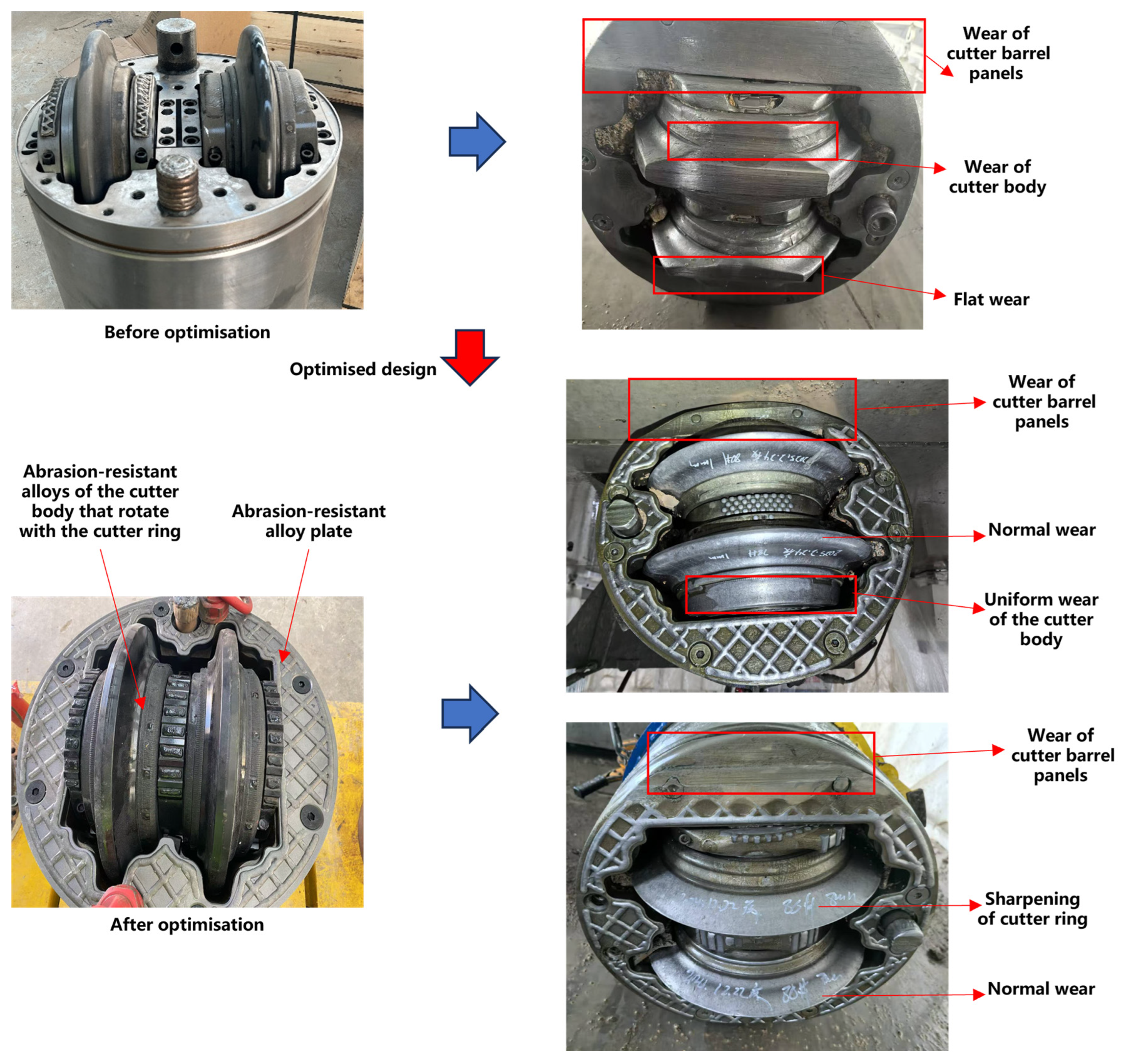
4.4. Optimization of Cutter and Cutter Barrel Wear Resistance

The abnormal wear of disc cutters in the edge area is severe, primarily due to the accumulation of rock chips in front of the cutterhead; this induces wear on the cutter body, which in turn allows sediment to enter the cutter bearings, causing the cutter to fail to rotate and resulting in flat wear. Subsequently, the wear of the disc cutter accelerates, and the scrapers also fail rapidly, leading to abnormal wear on the cutter barrel and the cutter body. To address this issue, two structural optimizations were implemented. First, wear-resistant alloy plates were added to the cutter barrel panel. Second, the structure of the disc cutter was optimized by adding wear-resistant alloy plates to the cutter body and enabling the cutter body to rotate together with the cutter ring. This optimization ensured that the accumulated rock chips wore the entire cutter body evenly, rather than concentrating wear on a specific area. As can be observed from Figure 21, the optimized disc cutter only displayed a sharpening of the cutter ring and uniform wear of the cutter body. However, the cutter barrel panel was severely worn despite the presence of an alloy plate for protection. Analysis suggests that the severe wear on the cutter barrel is caused by the failure of the scrapers along the corresponding trajectory. Therefore, the scrapers on the affected trajectory were replaced to reduce the wear on the cutter barrel caused by rock chip accumulation. The final effect is shown in Figure 22. It can be observed that, when the disc cutter reaches its wear limit, the cutter body exhibits uniform wear, and the cutter barrel panel shows only minor wear, which significantly improves the cutter’s life and reduces its maintenance costs.

4.5. Effect Ofdisc Cutter Wear Type on Engineering Effectiveness

Different degrees of cutter wear led to different economic and time losses. When the disc cutter exhibits normal wear, the wear rate is relatively slow, and TBM tunnelling with 20~30 rings can be maintained, greatly reducing the time for cutter replacement. Once the cutter barrel is clogged with clay, injecting the slurry dispersant to soak the mud cake is a costly expense, and the TBM must be shut down during the soaking process. Meanwhile, the clogging of the cutter barrel induces the cutter to stop rotating, and after just 1~2 rings of tunnelling, it is severely flat-worn and must be shut down to replace the cutter. Further, if the cutter body is worn, the entire cutter must be sent back to the manufacturer for total replacement, not just the cutter ring, and the cost of repairing the cutter rises sharply. More critically, once the cutter barrel is worn, it must be replaced, and due to the large size of the barrel, its production, transportation, and assembly process require large amounts of manpower and material resources. Actual projects should follow the principle of early detection, early replacement, and early maintenance to reduce abnormal wear and eliminate the wear of the cutter body and cutter barrel, aiming to maximize engineering benefits.

5. The Optimal Timing for Cutter Replacement

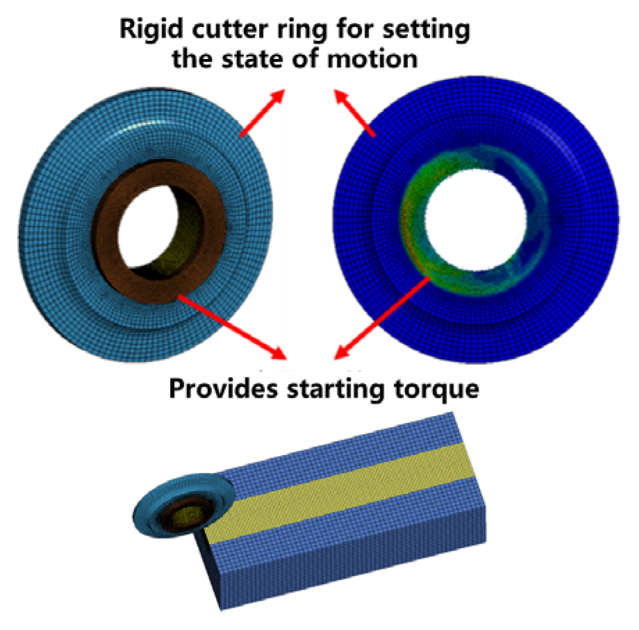
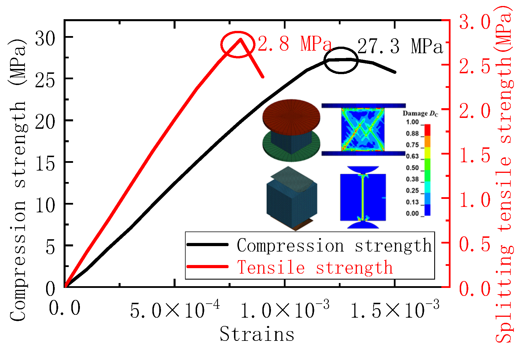
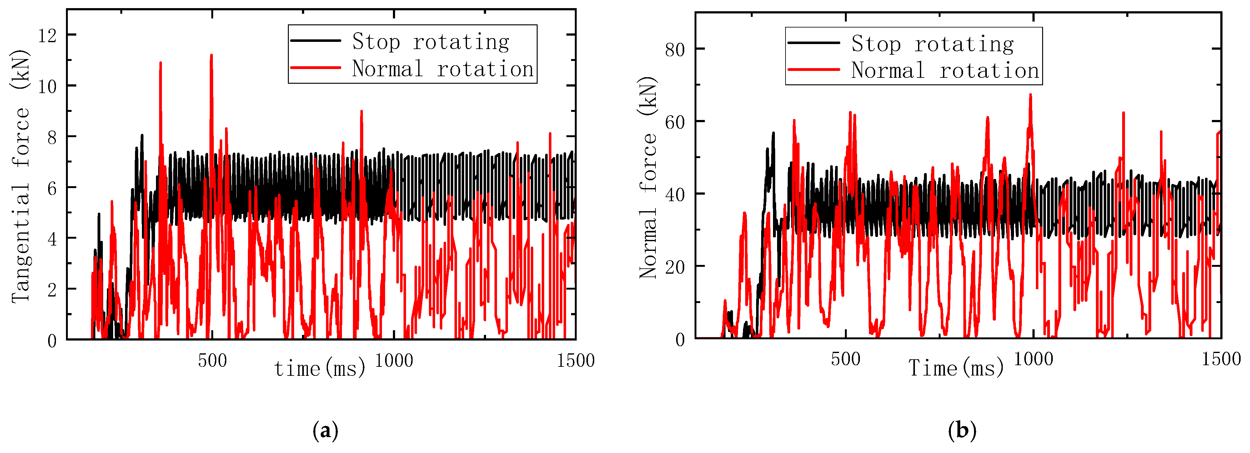
5.1. Numerical Simulation of Rock Breaking in Abnormal State of Rolling Cutter

In order to investigate the change in the rock-breaking mechanism under the normal rotation and stopping state of the disc cutter, a numerical simulation model of rock breaking by the disc cutter was established, and the force and rock-breaking effects were compared and analyzed.
The rock-breaking model of a single disc cutter is shown in Figure 23. The disc cutter is a 17-inch constant-cross-section cutter. In the simulation model of this study, the cutter ring is defined as a rigid body, assigned with a linear cutting motion while releasing rotational degrees of freedom. The cutter shaft position is set as an elastic constitutive model. A separate ring tightly presses against the cutter shaft, generating friction between them during cutter rotation, thereby providing the starting torque. When the friction force is relatively large, the starting torque of the disc cutter increases, causing the cutter to stop rotating during rock breaking. When the friction force is moderate, the rock-breaking force can overcome the starting torque, allowing the disc cutter to rotate normally.
The HJC (Holmquist–Johnson–Cook) and RHT (Riedel–Hiermaier–Thoma) constitutive models have been widely employed to describe the mechanical behaviour of rock and concrete materials when subjected to large strains and high strain rates [21]. Although both the HJC and RHT constitutions can represent the strain rate effect of rocks, the significant advantage of the RHT constitutions is the fact that the expansion pattern of rock cracks is more consistent with experiments [22]. This study selected the RHT constitutive model to describe the dynamic fracture behaviour of rock mass. The RHT constitutive model consists of two parts: the equation of state (Figure 24) and the constitutive equation (Figure 25). The equation of state describes the process of pore collapse and compaction in porous and loose media, while the constitutive equation describes the stress–strain characteristics of the material. Considering the relatively low strength of the rock mass in this project, the uniaxial compressive strength of the rock mass was set to 25 MPa in the simulation. Numerous scholars have conducted a series of studies on the dynamic failure of rocks and concrete based on the RHT model. The parameter values of the RHT model in these studies have been validated through simulations of SHPB tests and explosion tests [23,24]. Therefore, the RHT model parameter values in this study refer to these previous research findings, and their detailed values and principles can be found in [23,24].
To validate the mechanical parameters and crack propagation patterns of the numerical model, numerical uniaxial compression tests and splitting tensile tests were conducted. Figure 26 illustrates the process and results of the uniaxial compression and splitting tensile tests. The simulation tests perfectly represent the damage pattern of the rock mass, and some shear and tensile cracks keep expanding, which finally led to the rupture of the specimen, with a peak uniaxial compression strength of 27.3 MPa and a peak splitting compressive strength of 2.8 MPa. Therefore, the constituent parameters of the RHT principal of the rock mass were considered to be valid and were employed for the simulations described in the following sections. The cutting speed was set to 0.8 m/s with a penetration depth of 2.5 mm. The effect of rock crushing is presented in Figure 27.
When the cutter is rotating normally, significant compression crushing zones exist on both sides of the cutting groove, and the depth and width of the crack propagation are larger. When the disc cutter stops rotating, no significant compression-crushed zones are observed on both sides of the cutting groove, and the depth and width of crack propagation are significantly reduced. In practical engineering, if two disc cutters on adjacent trajectories both stop rotating, the cracks between the two disc cutters will not be able to penetrate.
Figure 28 presents the cutting forces under two cutting modes. When the disc cutter rotates normally, the load fluctuates significantly, with the tangential force varying around 3 kN and the normal force varying around 20 kN, reaching a peak normal force of up to 70 kN. When the disc cutter stops rotating, the rock-breaking tangential force increases significantly, while the peak normal force decreases. The tangential force varies around 6 kN, and the peak normal force drops to 50 kN with a reduced fluctuation amplitude. The significant decrease in the amplitude of load fluctuation and the remarkable change in the cutting load are attributed to the transformation of the rock-breaking mode from downward compression to forward cutting.

5.2. Determination of Cutter Replacement Timing in Practical Engineering

Based on the simulation results, it is evident that variations in the operational state of the disc cutter significantly affect the tangential force, and the cutterhead torque is the concentrated representation of the tangential forces from all disc cutters. Therefore, the torque will fluctuate significantly when the cutter state is changed. Figure 29 presents the trend of the tunnelling parameters during five cutter replacements. The cutterhead rotation speed is maintained at 1 r/min, with the tunnelling speed ranging between 8 and 12 mm, the torque between 8000 and 12,000 kN·m, and the thrust between 6600 and 8800 kN. Due to continuous variations in penetration depth, parameters such as thrust and torque do not directly reflect the operational state of the disc cutter. In practical engineering, the composite parameter P is defined as the ratio of thrust to penetration, and Q is the ratio of torque to penetration, which is used to determine the state of the cutter. The trends of the composite parameters during the five cutter replacements are shown in Figure 30. Near the 20th and 42nd rings, the composite parameters show a sharp increase. Considering that the geological boreholes reveal a significant increase in rock strength in these areas, and the disc cutter rotation monitoring system does not detect any disc cutter abnormalities, no cutter replacement is performed. In subsequent tunnelling processes, the sharp increase in composite parameters serves as one of the criteria for determining the timing of cutter replacement.

6. Discussion

This study was mainly based on the engineering practices in Qingdao Jiaozhou Bay large-diameter slurry TBM tunnelling in soil–rock composite strata. In terms of disc cutter wear, there are two typical types. The first is secondary wear due to the accumulation of rock and soil particles at the bottom in front of the cutterhead, which causes the cutter ring to sharpen. The second is the flat wear of disc cutters induced by factors such as rock chip accumulation in front of the cutterhead, skip-track cutter replacement, alloy-insert disc cutter mismatch, cutter barrel clogging, and severe wear of scrapers. As a result, a series of improvement measures have been taken such as slurry circulation to remove rock chips during TBM stoppage, clay dispersant injection into the slurry chamber, cutter barrel flushing, and the wear resistance optimization of cutters and cutter barrels.
These optimization measures are particularly suitable for working conditions where the strata contain a large amount of clay, such as fault fracture zone strata and soil–rock composite strata. Meanwhile, for the modification of the disc cutter and cutter barrel, the benefits are greatest when there is a serious accumulation of rock particles in front of the cutterhead. The optimizations are less meaningful and increase economic costs when there is no rock accumulation in front of the cutterhead. In the future, when designing large-diameter slurry TBM, the following three aspects should be particularly optimized:
(1)
The flow rate of the slurry circulation system should be further increased to reduce the accumulation of rock particles in front of the cutterhead and reduce the secondary wear of the cutter.
(2)
Wear-resistant design of the cutter body and cutter barrel should be especially focused on, rather than just paying attention to the wear-resistant performance of the cutter ring.
(3)
The cutter ring not only cuts the complete rock mass, but is also continuously abraded by the broken rock particles. Therefore, in the selection of cutter materials, both the impact and abrasion resistance should be considered in order to improve the life of the cutter.

7. Conclusions

In this study, taking the Qingdao Jiaozhou Bay Second Subsea Tunnel Project as the background, the wear patterns of disc cutters on the atmospheric cutterhead of a large-diameter slurry TBM under complex geological conditions were analyzed. The flat wear of disc cutters induced by factors such as rock chip accumulation in front of the cutterhead, the jump trajectory when changing disc cutters, alloy-insert disc cutter mismatch, cutter barrel clogging, and severe wear of scrapers is discussed. Furthermore, the impacts of measures such as slurry circulation to remove rock chips during TBM stoppage, clay dispersant injection into the excavation chamber, cutter barrel flushing, and the wear resistance optimization of cutters and cutter barrels on reducing cutter wear were investigated. Based on numerical simulations and field data, a methodology for determining the optimal timing for cutter replacement is proposed.
(1)
The primary failure modes of disc cutters on large-diameter atmospheric cutterheads can be categorized into four types: normal wear, flat wear, fracture, and cutter ring sharpening. The secondary wear of disc cutters in the edge area is relatively severe, manifested as accelerated cutter wear, cutter ring sharpening, and wear on the cutter body and barrel. This indicates a certain degree of rock particle accumulation at the bottom of the atmospheric cutterhead.
(2)
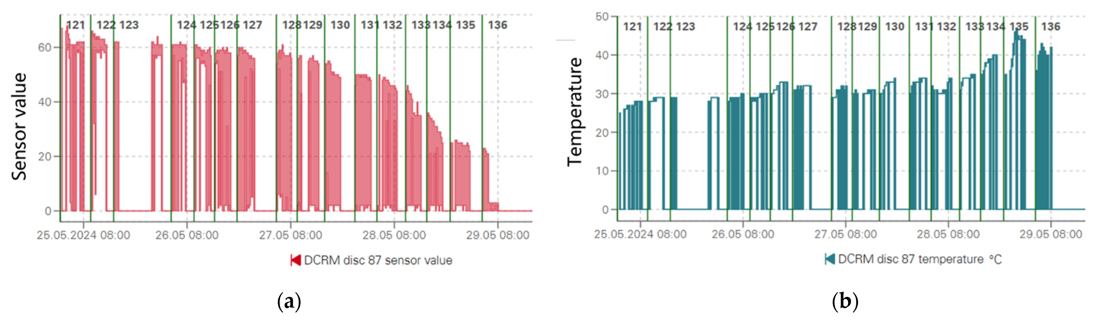
The DCRM cutter rotation and temperature monitoring system can well identify the flat wear of a single disc cutter, which is significantly characterized by a decreasing rotation value of the cutter and a remarkable increase in temperature. Cutter replacement with trajectory jumping will result in the failure of synergistic rock breaking, inducing persistent flat wear of the disc cutter. The clogging of the cutter barrel will prevent the disc cutter from rotating, leading to flat wear. Severe wear of the scrapers will cause a significant accumulation of rock chips in front of the cutterhead, triggering secondary wear of the disc cutter and cutter barrel.
(3)
Adopting measures such as shield shutdown, a circulation system to carry away the slag, cutter barrel flushing, and soaking in 2% dispersant for 8 h can effectively reduce the accumulation of rock chips and mud cakes on the cutterhead, which in turn reduces the flat wear of the disc cutter. Adding a cutter body and wear-resistant barrel alloy, optimizing the cutter structure to make the cutter body and cutter ring rotate synchronously, and replacing the severely worn scraper promptly can effectively reduce the secondary wear of the cutter barrel and cutter caused by the accumulation of rock chips in front of the cutterhead, improving the life of the cutter.
(4)
Based on the dynamic damage constitutive of RHT, a rock-breaking model considering the rotation of the disc cutter was established; the results show that the width and depth of the rock damage zone are significantly reduced after the disc cutter stops rotating, and the tangential force is significantly increased, which leads to an increase in the torque of the cutterhead. The sharp increase in composite parameters can serve as an effective marker for assessing cutter conditions and determining the optimal timing for cutter replacement.

Author Contributions

Software, Y.G.; Validation, Y.F.; Formal analysis, X.L.; Investigation, Y.C.; Resources, Y.C. and H.L.; Data curation, Y.G.; Writing—original draft, Y.F.; Writing—review & editing, X.L.; Project administration, H.L.; Funding acquisition, X.L. All authors have read and agreed to the published version of the manuscript.

Funding

This research was funded by the National Science Foundation of China under grant number 52278386 and The APC was funded by the National Science Foundation of China.

Data Availability Statement

The original contributions presented in the study are included in the article, further inquiries can be directed to the corresponding author.

Acknowledgments

The authors would like to acknowledge the National Science Foundation of China under Grant No. 52278386 for supporting this research.

Conflicts of Interest

Authors Yinggui Cao and Hongzhi Liu were employed by the company CCCC Tunnel Engineering Bureau Co., Ltd. The remaining authors declare that the research was conducted in the absence of any commercial or financial relationships that could be construed as a potential conflict of interest.

References

  1. Tang, S.; Zhang, X.; Liu, Q.; Xie, W.; Wu, X.; Chen, P.; Qian, Y. Control and prevention of gas explosion in soft ground tunneling using slurry shield TBM. Tunn. Undergr. Space Technol. 2021, 113, 103963. [Google Scholar]
  2. Tang, S.; Zhang, X.; Liu, Q.; Xie, W.; Yang, X.; Chen, P.; Tu, X. Analysis on the excavation management system of slurry shield TBM in permeable sandy ground. Tunn. Undergr. Space Technol. 2021, 113, 103935. [Google Scholar] [CrossRef]
  3. Guo, Y.; Fang, Y.; Li, X.; Jin, D.; Liu, H. Simulation of screening characterization of double-deck vibrating screen of slurry TBM tunnelling using integrated CFD-DEM-FEM. Tunn. Undergr. Space Technol. 2025, 158, 106399. [Google Scholar]
  4. Su, W.; Li, X.; Jin, D.; Yang, Y.; Qin, R.; Wang, X. Analysis and prediction of TBM disc cutter wear when tunneling in hard rock strata: A case study of a metro tunnel excavation in Shenzhen, China. Wear 2020, 446–447, 203190. [Google Scholar]
  5. Cho, J.W.; Jeon, S.; Yu, S.H.; Chang, S.H. Optimum spacing of TBM disc cutters: A numerical simulation using the three-dimensional dynamic fracturing method. Tunn. Undergr. Space Technol. 2010, 25, 230–244. [Google Scholar]
  6. Duan, Y.; Yuan, D.; Wu, J.; Deng, X.; Wu, B.; Sun, Z. Effect of the Geometric Configuration of the Disc Cutter on the Cutting Behaviour in Tunneling. Appl. Sci. 2023, 13, 72. [Google Scholar]
  7. Stopka, G. Modelling of rock cutting with asymmetrical disc tool using discrete-element method (DEM). Rock Mech. Rock Eng. 2021, 54, 6265–6279. [Google Scholar] [CrossRef]
  8. Lin, L.; Li, R.; Luo, X.; Xia, Y. Comparative study on the rock breaking performance of constant cross section disc cutter and inserted tooth disc cutter for cutting granite. Tunn. Undergr. Space Technol. 2024, 150, 105840. [Google Scholar]
  9. Agrawal, A.K.; Chattopadhyaya, S.; Murthy, V.M.S.R. Delineation of cutter force and cutter wear in different edge configurations of disc cutters—An analysis using discrete element method. Eng. Fail. Anal. 2021, 129, 105727. [Google Scholar]
  10. Gou, B.; Zhang, M. Effects of surface grooves on rock cutting performance and contact behavior of a TBM disc cutter. Eng. Fract. Mech. 2022, 267, 108466. [Google Scholar]
  11. Lu, G.; Zhou, J.; Zhang, L.; Gao, W. Experimental investigation on the influence of microwave exposure on the cutting performance of TBM disc cutter cutting of hard rocks. Results Eng. 2021, 12, 100285. [Google Scholar]
  12. Pan, Y.; Liu, Q.; Liu, J.; Liu, Q.; Kong, X. Full-scale linear cutting tests in Chongqing Sandstone to study the influence of confining stress on rock cutting efficiency by TBM disc cutter. Tunn. Undergr. Space Technol. 2018, 80, 197–210. [Google Scholar]
  13. Zhang, N.; Shen, S.; Zhou, A.; Chen, X. Identification of cutter flat wear for rock TBMs using vibration signal of shield. Mech. Syst. Signal Process. 2025, 223, 111885. [Google Scholar]
  14. Li, X.; Zhang, M.; Mo, J. Wear and abnormal fracture failure mechanisms of alloy teeth in TBM insert tooth disc cutters. Eng. Fail. Anal. 2025, 167, 109051. [Google Scholar]
  15. Hu, G.; Zhao, H.; Fu, J.; Xue, J.; Xia, Y. Impact fracture failure analysis and mechanism study of a TBM disc cutter ring. Eng. Fail. Anal. 2024, 163, 108508. [Google Scholar]
  16. Xue, Y.; Zhou, J.; Liu, C.; Shadabfar, M.; Zhang, J. Rock fragmentation induced by a TBM disc-cutter considering the effects of joints: A numerical simulation by DEM. Comput. Geotech. 2021, 136, 104230. [Google Scholar]
  17. Aghababaei, R.; Zhao, K. Micromechanics of material detachment during adhesive wear: A numerical assessment of Archard’s wear model. Wear 2021, 476, 203739. [Google Scholar]
  18. Huang, X.; Liu, Q.; Liu, B.; Wang, D.; Wang, X.; Zeng, C. Development and in-situ application of a real-time cutting tool forces monitoring system in TBM tunnelling. Tunn. Undergr. Space Technol. 2022, 124, 104453. [Google Scholar]
  19. Zhang, Z.; Zhang, K.; Dong, W.; Zhang, B. Study of rock-cutting process by disc cutters in mixed ground based on three-dimensional particle flow model. Rock Mech. Rock Eng. 2020, 53, 3485–3506. [Google Scholar]
  20. Fang, Y.; Yao, Z.; Xu, W.; Tian, Q.; He, C.; Liu, S. The performance of TBM disc cutter in soft strata: A numerical simulation using the three-dimensional RBD-DEM coupled method. Eng. Fail. Anal. 2021, 119, 104996. [Google Scholar]
  21. Song, S.; Xu, X.; Ren, W.; Liu, S.; Jiang, J. Determination and application of the RHT constitutive model parameters for ultra-high-performance concrete. Structures 2024, 69, 107488. [Google Scholar]
  22. Zhu, Y.; Song, K.; Luo, Y.; Qu, D.; Li, X.; Liu, T.; Zhang, J. Analyzing the dynamic failure process of coral reef limestone through digital core-based numerical trials. Comput. Geotech. 2024, 172, 106489. [Google Scholar]
  23. Xie, L.X.; Lu, W.B.; Zhang, Q.B.; Jiang, Q.H.; Chen, M.; Zhao, J. Analysis of damage mechanisms and optimization of cut blasting design under high in-situ stresses. Tunn. Undergr. Space Technol. 2017, 66, 19–33. [Google Scholar]
  24. Abdel-Kader, M. Modified settings of concrete parameters in RHT model for predicting the response of concrete panels to impact. Int. J. Impact. Eng. 2019, 132, 103312. [Google Scholar]
Figure 1. Geological profile of the tunnel (0~270 rings).
Lubricants 13 00170 g001
Figure 2. Physical structure of the cutterhead.
Lubricants 13 00170 g002
Figure 3. The typical position of the cutter trajectory layout. (a) Atmospheric pressure for replaceable disc cutters in the edge area. (b) Atmospheric pressure for replaceable scrapers in the edge area. (c) Scrapers welded to the cutterhead.
Lubricants 13 00170 g003
Figure 4. Detailed dimensions of disc cutter and barrel.
Lubricants 13 00170 g004
Figure 5. Layered deployment of three types of cutters.
Lubricants 13 00170 g005
Figure 6. Typical cutter wear patterns. (a) Typical cutter failure modes. (b) Partial sharpening of the front face cutter. (c) Sharpening of the cutter in the edge zone.
Lubricants 13 00170 g006aLubricants 13 00170 g006b
Figure 7. Rate of cutter wear when changing cutters in ring 56.
Lubricants 13 00170 g007
Figure 8. Cutter wear from rings 57 to 98.
Lubricants 13 00170 g008
Figure 9. Failure of alloy-insert disc cutter.
Lubricants 13 00170 g009
Figure 10. Working principle of the DCRM system.
Lubricants 13 00170 g010
Figure 11. DCRM disc cutter status monitoring interface. (a) Disc cutter rotation monitoring interface. (b) Disc cutter temperature monitoring interface.
Lubricants 13 00170 g011
Figure 12. The 104~136 ring cutter damage.
Lubricants 13 00170 g012
Figure 13. The mechanism by which skip-track cutter replacement induces flat wear.
Lubricants 13 00170 g013
Figure 14. Cutter barrel clogging induces flat wear.
Lubricants 13 00170 g014
Figure 15. Severe wear on the cutter ring, cutter body, and cutter barrel.
Lubricants 13 00170 g015
Figure 16. Wear of disc cutters in different installation zones. (a) Wear of front disc cutter. (b) Extensive flat wear of edge disc cutters. (c) Extensive flat wear and fracture of edge disc cutters.
Lubricants 13 00170 g016aLubricants 13 00170 g016b
Figure 17. Changes in tunnelling speed and torque when the circulation system carries rock and soil particles.
Lubricants 13 00170 g017
Figure 18. Tests on clay blocks immersed in different percentages of dispersant.
Lubricants 13 00170 g018
Figure 19. Testing the mixing of different percentages of dispersant with the slurry.
Lubricants 13 00170 g019
Figure 20. The on-site clay dispersant injection process and final results.
Lubricants 13 00170 g020
Figure 21. Wear condition after the wear-resistant design of the cutter body and barrel.
Lubricants 13 00170 g021
Figure 22. Wear condition of the cutter barrel after replacing the severely worn scraper corresponding to the trajectory.
Lubricants 13 00170 g022
Figure 23. Rock-breaking model considering the starting torque of the cutter.
Lubricants 13 00170 g023
Figure 24. P-α equation of state.
Lubricants 13 00170 g024
Figure 25. Stress limit surfaces.
Lubricants 13 00170 g025
Figure 26. Numerical uniaxial compression and the Brazilian splitting process.
Lubricants 13 00170 g026
Figure 27. Rock damage when the cutter stops rotating.
Lubricants 13 00170 g027
Figure 28. Cutting forces for different cutter states. (a) tangential force. (b) normal force.
Lubricants 13 00170 g028
Figure 29. Trends in thrust and torque.
Lubricants 13 00170 g029
Figure 30. Trends in composite parameters.
Lubricants 13 00170 g030
Table 1. Main operating parameters of the shield machine.
ParameterValue
Main machine length of TBM (m)15.81
Advancing rate (mm/min)0~50
Excavation diameter (m)15.63
Cutterhead opening ratio (%)30
Cutterhead rotational speed (rpm)0~1.74
Working soil and water pressure (bar)0~10
Torque (kN·m)0~42,968
Thrust (kN)0~287,056
Adapted maximum gradient (‰)0~50
Minimum turning radius (m)800
Disclaimer/Publisher’s Note: The statements, opinions and data contained in all publications are solely those of the individual author(s) and contributor(s) and not of MDPI and/or the editor(s). MDPI and/or the editor(s) disclaim responsibility for any injury to people or property resulting from any ideas, methods, instructions or products referred to in the content.

