Article

Effects of Contact Characteristics on Dynamic Response of Planar Mechanical Systems with Lubricated Revolute Joint

1
School of Chemistry and Chemical Engineering, Nanjing University of Science and Technology, Nanjing 210094, China
2
School of Mechanical Engineering, Jiangsu University of Technology, Changzhou 213001, China
3
School of Mechanical Engineering, Nanjing University of Science and Technology, Nanjing 210094, China
*
Author to whom correspondence should be addressed.
Lubricants 2025, 13(3), 124; https://doi.org/10.3390/lubricants13030124
Submission received: 2 January 2025 / Revised: 5 February 2025 / Accepted: 13 March 2025 / Published: 14 March 2025

Abstract

:
In this study, a dynamic response model that incorporates lubricated clearance is developed to examine the evolution of contact and friction in a mechanical system. The dynamic model of a lubricated clearance joint is established by considering the contact, friction, and hydrodynamics. The expression of contact force in normal and tangential directions is developed using elastic contact theory. The lubrication characteristics of a revolute joint are obtained using hydrodynamic theory, which is introduced into the simulation model. This case study is conducted to investigate the effects of design parameters on the dynamic stability of a mechanical system with a lubricated clearance joint. The results elucidate the relationship between lubrication characteristics and vibration response, offering valuable insights for the optimization of mechanical systems.

1. Introduction

In ideal conditions, the concentricity of a journal center and bearing center is incorporated into the design of a mechanism. However, clearance can change the constraint condition of the center trajectory, and a kinematic state indicates diversification. The motion deviation changes the trajectory of the mechanism [1,2,3,4]. The contact and friction of a revolute joint can cause deformation of the contact point, and the transient impact force damages the surface structure, which is also a key element in reducing dynamic stability. Additionally, the transmission characteristics of the mechanical property are the object that needs to be explored in the investigation of mechanism dynamics. If the motion state of mechanical systems always maintains chaotic characteristics, the manufacturing accuracy and dynamic repeatability position will be destroyed [5,6,7,8]. Moreover, lubricating the revolute joint can improve the complexity of the mechanism motion. Thus, an approach should be proposed that accurately represents the dynamic response and mitigates adverse influence.
The modeling method is an important aspect of the dynamic behavior evaluation of precision mechanisms [9,10]. Erkaya [11] designed an experimental platform to reveal the influence of the clearance joint on the dynamic stability of mechanical systems. Variations in load and working speed were used to obtain the analysis objective and coupled effects, which provide a reference for mechanism design. Bai [12,13] described a contact force model, which was a key element in evaluating the deviation of clearance joint elements. The relationship between deformation and material parameters was given in the dissipative term, and a new expression of contact force was presented. Based on the Lagrangian method, Zheng [14] built a descriptive model of a clearance joint, and the normal force-of-contact point was obtained with a Hertz contact model. To improve calculation efficiency, the calculation of friction force was transferred using the linear complementarity problem (LCP) approach. Li [15] conducted a numerical analysis of angular error uncertainty and kinematic deviation in a multiple-loop mechanism. The constraint condition of dynamic equations was the key element in the introduction and solution of a dynamic model for a clearance joint. Considering the effects of inertial force, Muvengei [16] proposed a modeling method of vibration response analysis for a mechanism with a clearance joint. The numerical results showed that the location of the clearance joint determined what kind of vibration would occur in the connecting rod, which damaged the stability of the mechanism during motion. Rahmanian [17] evaluated a method for describing the elastic deformation and vibration characteristics of a multibody system. The Poincaré portrait was used to show the periodic behavior of this mechanism, and the nonlinear dynamics of the mechanism were revealed. Taking displacement restoring capacity and wear failure into account, Li [18,19] established a dynamic model of an unfolding board for solar array systems, which represented the nonlinear contact characteristics. The results showed that the design of an equivalent stiffness and damping coefficient played an important role in the mechanism with a clearance joint. Flores [20] investigated the effects of the distribution of clearance joints on the dynamic characteristics of multibody systems, and a dynamic model of a mechanism with multiple clearance joints was proposed, which provided a reference for the key parameter design of high-precision mechanisms.
Lubrication effects always appear in the clearance joint, and a computational approach is the main focus of one study, which includes the methods of establishing the lubrication characteristic and supporting force of a journal [21]. Zhao [22] developed a theoretical expression of lubricant oil film with the Navier–Stokes equations, which discussed the effect of oil film pressure variation on the supporting force of a journal. The kinematic behavior of mechanical systems was upgraded by the lubrication effects. Flores [23] compared the center trajectory of a journal with different lubricant characteristics. The results showed that the lubricated clearance joint could provide a better support force for the impact effects of contact elements and that the initial contact velocity could be slowed down. Considering the transmission of motion state for clearance joints, Daniel [24] developed the lubrication expression of a clearance joint, which was described by the differential momentum equation. Chen [25] built a vibration prediction model of multibody systems with clearance joints, which included the lubrication characteristics and was flexible. The squeeze force of an oil film was described with a modified Pinkus–Sternlicht model, and the loading capacity was also obtained. Moreover, Jin [26] established the geometrical relationship and constraint condition of a six-linkage mechanism designed by Adams. The expression of a lubricated clearance joint was input into the formulations of multibody systems. This method could provide a reference for developing a 3D dynamic model of a mechanism with a lubricated clearance joint. In addition, Song [27] compared the influence of different lubrication types on the motion trajectory of a clearance joint using a new numerical approach. The study explored the complementary problem of contact reaction force, and the collision velocity was improved. Li [28] described the nonlinear dynamic behavior of a high-speed mechanism using a new approach and examined the influences of contact impact on the dynamic response of a clearance joint in a steady state. The results showed that the introduction of nodal coordinate formulation (NCF) and absolute nodal coordinate formulation (ANCF) expression could improve the computational efficiency of dynamic equations.
According to the above studies, the mapping relationship between the lubrication characteristics and nonlinear dynamic stability in a mechanical system is reduced, while some investigations focus on the nonlinear dynamic behavior. Thus, a new modeling approach of mechanical systems with lubricated clearance joints is proposed in this work. The dynamic equations of multibody systems are established with the Lagrangian method, and the contact feature can be expressed using the dissipative contact theory. Based on the Sommerfeld boundary condition, the hydrodynamics of a lubricated clearance joint are explored. Additionally, this study examines how the lubricant feature and clearance joint influence the dynamic behavior of the mechanism, while also focusing on variations in vibration and center trajectory.
The work is organized as follows: The theatrical model of the clearance joint and lubricant characteristics is established in Section 2. Section 3 displays the dynamic model of mechanical systems. A case study is conducted in Section 4, and the experiment is performed in Section 5. Finally, the conclusion is summarized in Section 6.

2. Dynamic Modeling of Revolute Clearance Joint Considering Lubrication

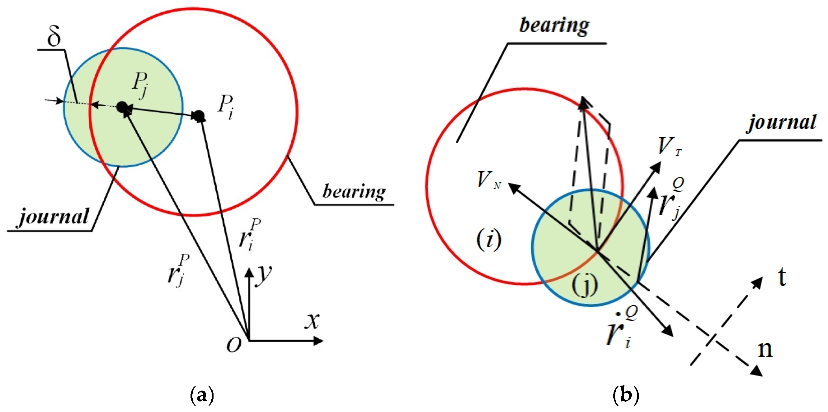
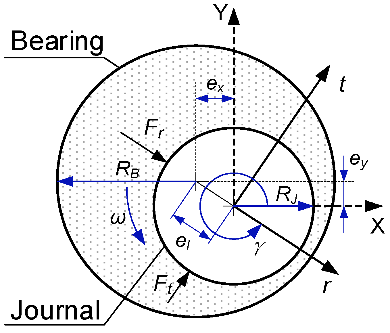
2.1. Modeling of Revolute Clearance Joint

The mass center positions of the components are defined as O i and O j . P i and P j are the center position of the journal and bearing in Figure 1. The motion synchronicity of the journal and bearing can be designed in an ideal condition. However, the deviation in motion trajectory is founded by different radius sizes, which is also the reason for the contact impact characteristics. In a global coordinate system, the eccentricity (e) of the journal and bearing is obtained with position vectors ( r i P and r j P ), which is written as [29,30,31,32]:
e = r j P r i P
n = e e
δ = e c
where n is the normal vector of the contact point and δ is the penetration value, which is obtained by calculating the difference between the eccentricity and the radius.
The position vector and velocity vector of the contact point are expressed as:
r k P = r k O + R k n         k = i , j
r ˙ k P = r ˙ k O + R k n ˙         k = i , j
where R i and R j are the radii of the journal and the bearing.
In addition, the contact velocity is a key factor for representing the motion, and it is divided by the normal vector ( ν n ) and the tangential vector ( ν t ), which are given as:
ν n = r ˙ j Q r ˙ i Q · n
ν t = r ˙ j Q r ˙ i Q   · t
where t and n are the vectors of the tangential and normal directions.

2.2. Modeling of Contact and Friction Characteristics

During the motion of the revolute clearance joint, the relative motion of the journal and bearing causes misalignment, and the contact is found at the interface [33,34,35,36]. Then, the acting force is obtained with the normal force ( F n ) and tangential force ( F t ), which are expressed as:
F = i f     δ 0 : F n + F t i f     δ < 0 : 0
The concern is that, over time, an energy loss emitted from the contact impact could be produced. Then, the hysteresis damping term should be given in the normal force model. It is written as:
F n = K δ 3 / 2 + C δ δ ˙       k = r , t
where K and C δ are the damping coefficients.
C δ = S T E P ( δ , 0 , 0 , d m a x , c m a x ) = i f             δ 0 : 0 i f     0 < δ < d m a x : c m a x δ d m a x 2 3 2 δ d m a x i f             δ d m a x : c m a x
where the maximum damping coefficient ( c m a x ) and the maximum penetration value ( d m a x ) are defined to limit the calculation boundary, which is defined as 0.1 and 0.01 mm.
The contact phenomenon causes a friction feature in the tangential direction, and it is usually established using Coulomb friction theory:
F t = μ d c d F n ν t ν t
c d =   0 i f             ν t ν 0         ν t ν 0 ν m ν 0 i f       ν 0 ν t ν m 1 i f               ν t ν m
where μ d and c d are is the friction coefficient of sliding and dynamics, and ν 0 and ν m are the limit boundary value of friction velocity.

2.3. Modeling of Lubrication Force

Lubrication relieves the contact impact characteristics, and the oil pressure can provide a supporting force for preventing the relative motion of the clearance joint (Figure 2) [37,38]. Additionally, the hydrodynamic response is displayed in the radius direction and vertical direction, which is given as:
F r = 12 μ L R k 2 c 2 ε 2 ω 2 γ ˙ 2 2 + ε 2 1 ε 2 + ε ˙ 1 ε 2 1.5 π 2 8 π 2 + ε 2
F t = 12 μ L R k 2 c 2 π ε ω 2 γ ˙ 2 2 + ε 2 1 ε 2 0.5 + 2 ε ε ˙ 2 + ε 2 1 ε 2
where L , ω , and ε are the bearing length, relative velocity, and eccentricity ratio.
In addition, the expression of the offset angle γ can be calculated as:
γ = a r c t a n e y e x
γ ˙ = d t a n 1 e y / e x d t = e x e ˙ y e ˙ x e y e 2
For the convenience of calculation, the hydrodynamic force of the oil film can be transferred to the component force in the X direction and Y direction, that is,
F l u b = F x F y = F r c o s γ F t s i n γ F r s i n γ F t c o s s γ

3. Dynamic Equation of Mechanical System with Clearance Joint

The mechanical system with a clearance joint is presented in Figure 3, which includes a crank, a connecting rod, and a slider [39,40]. The clearance joint is often located in the connecting point (connecting rod and slider). The revolute clearance joint is located between the connecting rod and the slider. Based on the Lagrangian multiplier method, the dynamic equation of the mechanical system is written as:
M ϕ q T ϕ q 0 q ¨ λ = Q + F c γ 2 α Φ β 2 Φ ˙
where M represents the mass matrix, λ is the Lagrangian multiplier, and ϕ q denotes the Jacobi matrix. Q is the generalized force matrix and F c is the external force. The variables α and β are the correction coefficients.
During the motion of mechanical systems, the relative position of contact points is employed to check the contact phenomenon, which is expressed as:
δ q t T δ q t + t < 0
The solution method can be limited in terms of the accuracy and efficiency of calculation. The solution flowchart of a mechanical system with a revolute clearance joint is displayed in Figure 4. Based on the geometry parameters and materials characteristics, the mathematical model of the mechanical system is built in Matlab 2016a. The contact stiffness and vectors (position, velocity, and acceleration) are calculated. Meanwhile, the mass matrix and generalized force should also be evaluated. Then, the dynamic equation of the mechanical system is solved by the fourth-order Runge–Kutta method. The important parameters of the iteration timestep and convergence accuracy should be given in the calculation. If the solution is divergent, the calculate variable should be reevaluated until convergence accuracy is achieved.

4. Case Study

As the key manufacturing tool, the press machine is used in engineering for industry production, agricultural machinery, and medical equipment. The kinematic accuracy and dynamic stability of this machine should be evaluated for the design of technology with a high-precision mechanism. The slider crank mechanism is the traditional type of transmission mechanism, and the dynamic behavior of the slider crank is investigated in this work. The structural parameters include the crank length (15 mm), connecting rod length (350 mm), crank mass (453.87 kg), connecting rod (412.53 kg), and slider mass (2700.71 kg). Moreover, steel is used to manufacture the materials, and the parameters include the density (7800 kg/m3), contact stiffness (2.34 × 10¹⁰ N/m), and friction coefficient (0.01). The results elucidate the relationship between the key functional parameters and the lubrication characteristics.

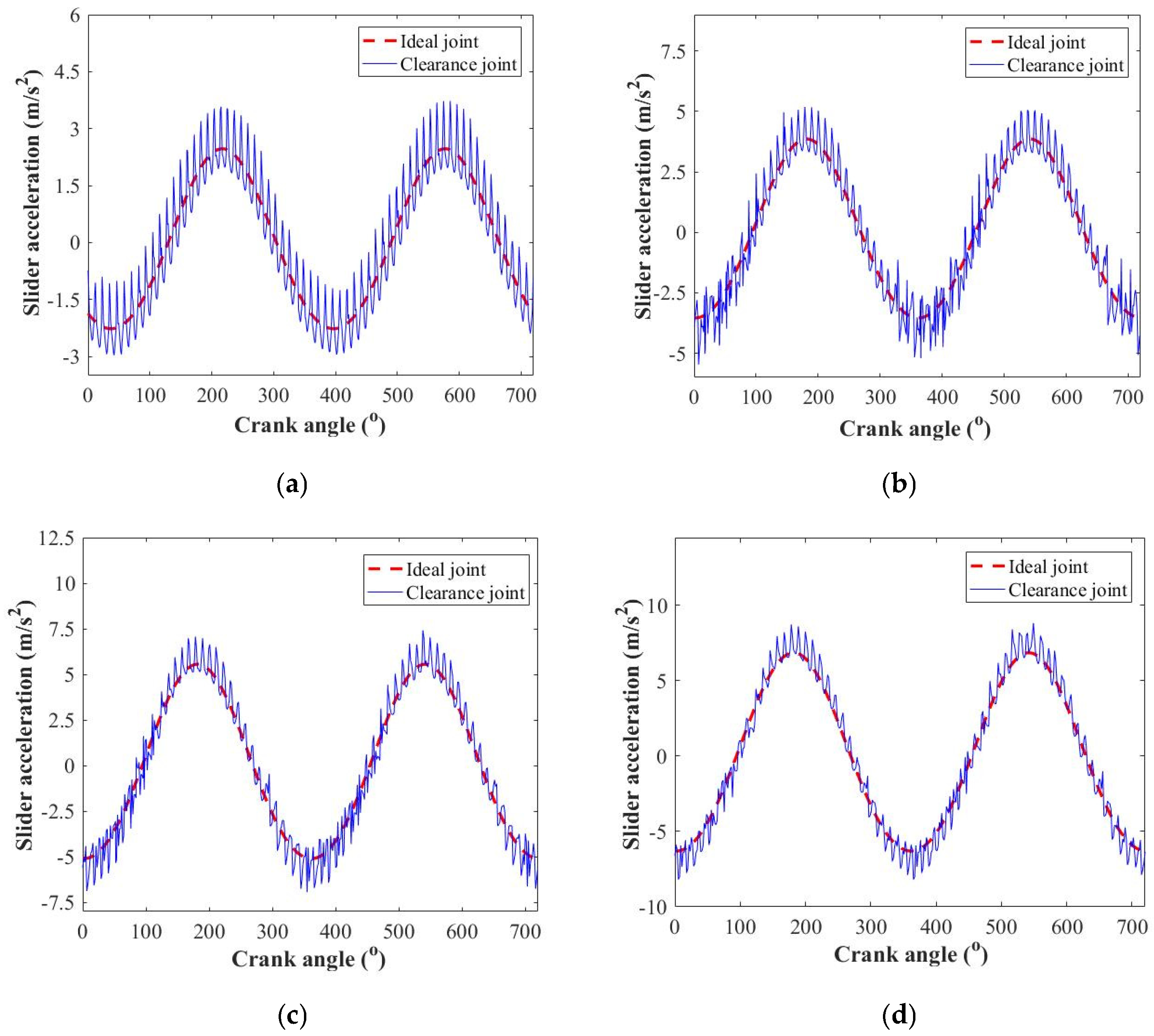
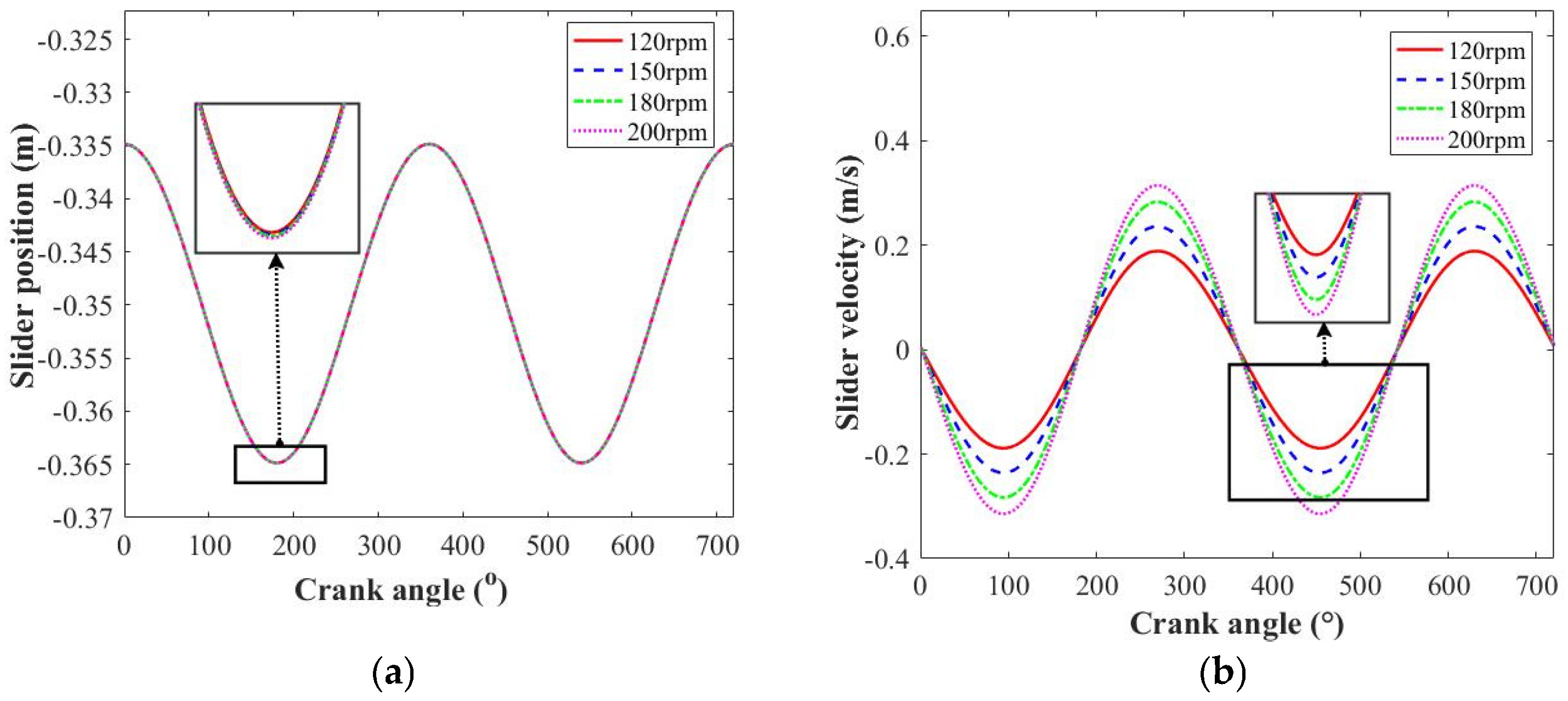
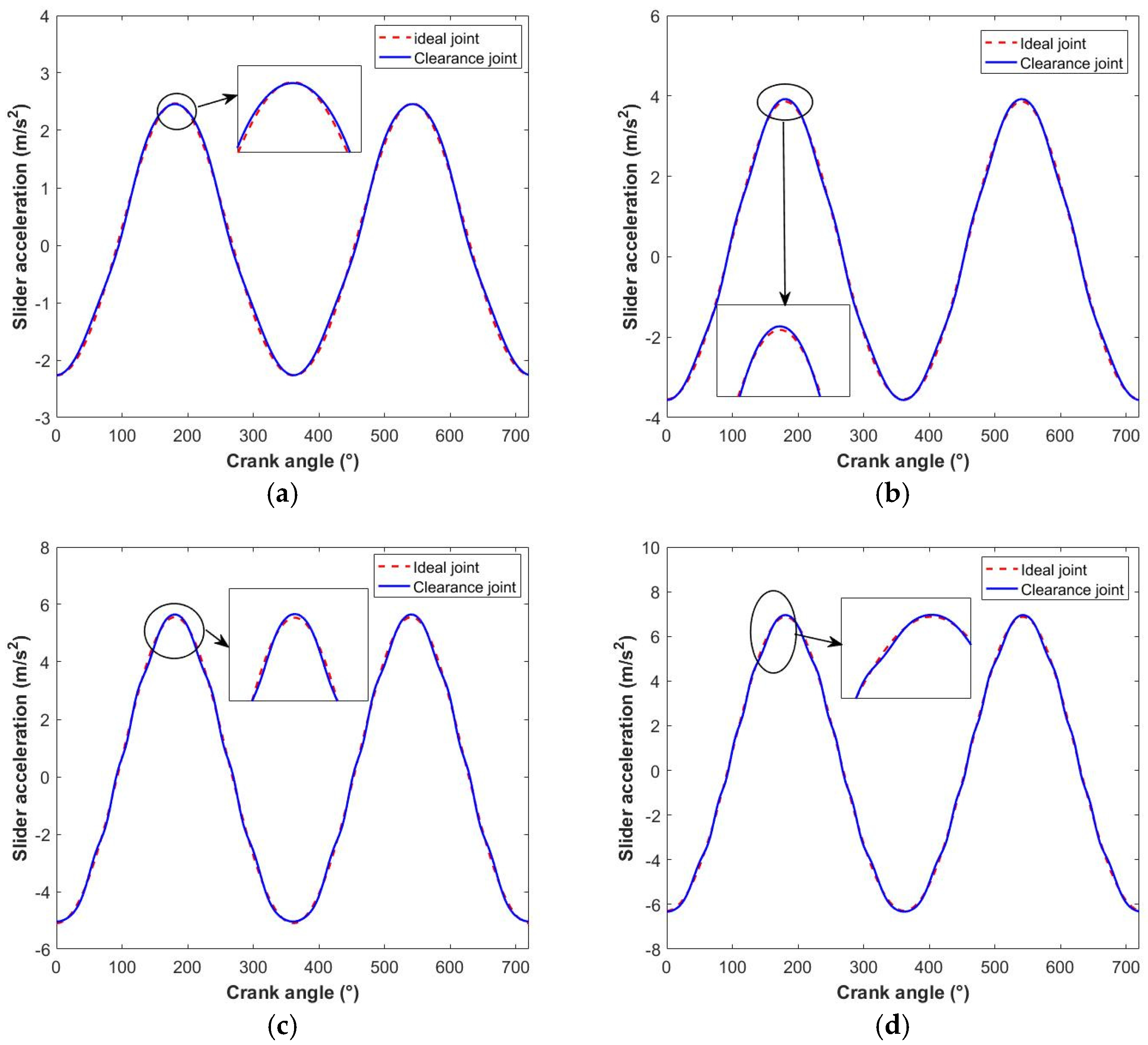
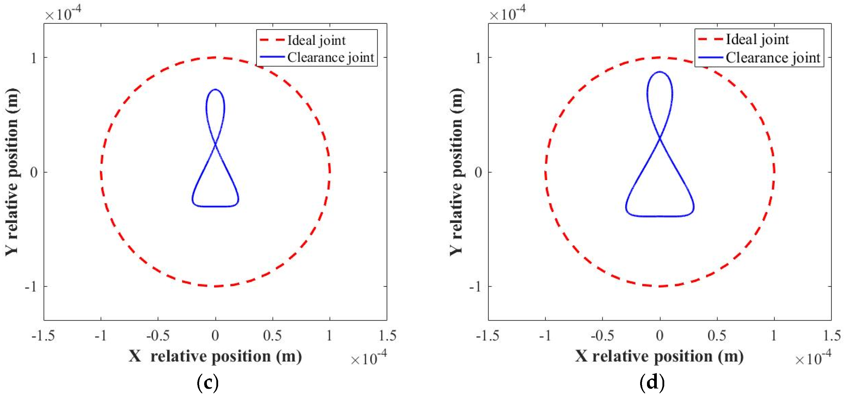
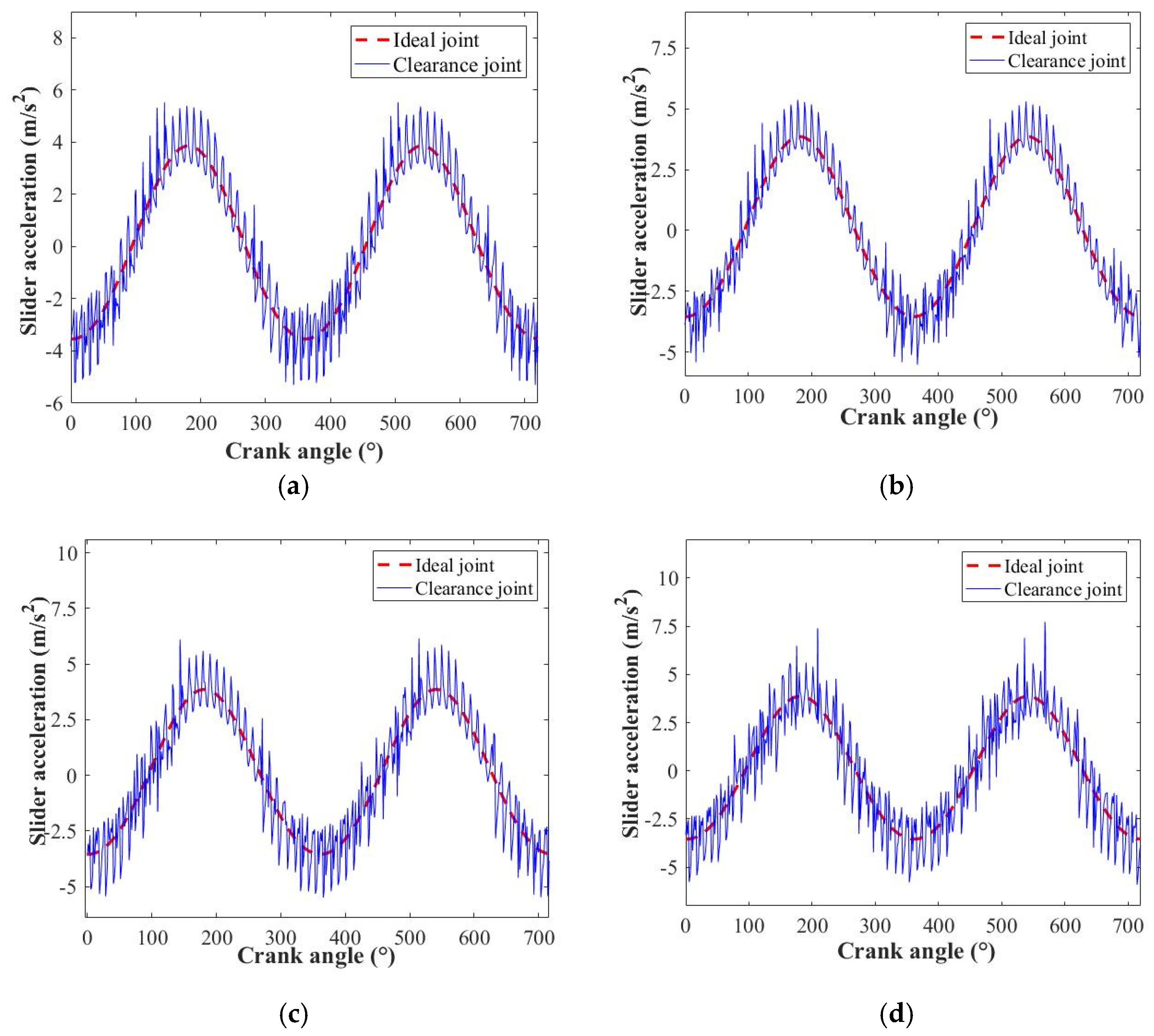
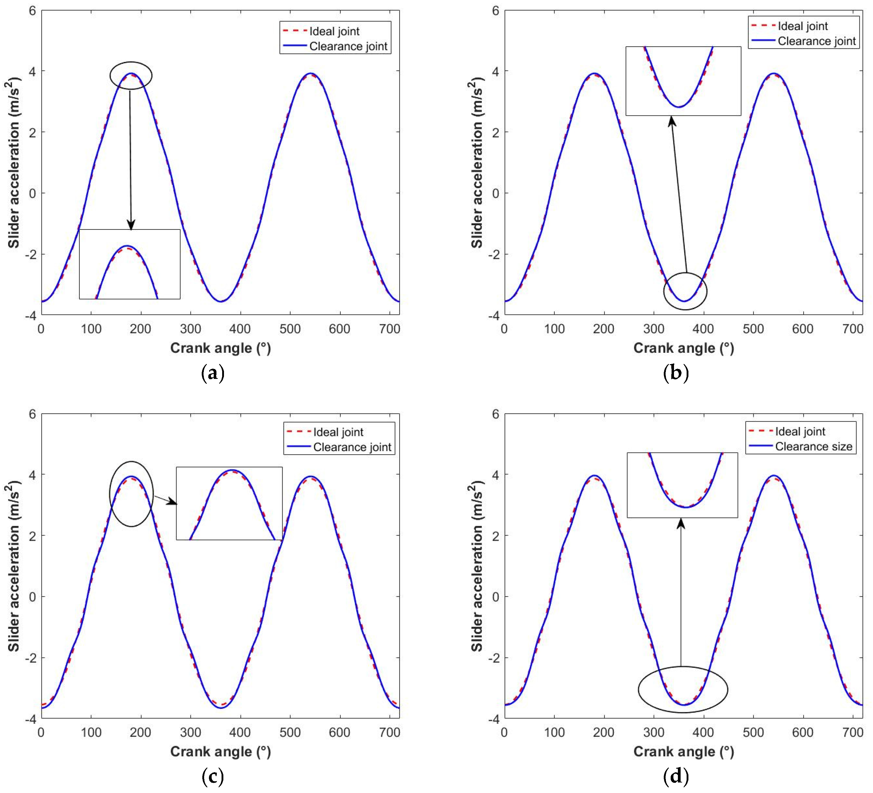
4.1. Influence of Rotation Speed

Considering the effects of rotation speed, the dynamic behavior of the slider crank mechanism with a clearance joint can be evaluated, which represents the adaptability of the mechanism to different working conditions. With the same clearance value (0.1 mm), rotation speed is chosen as the variable (120 rpm, 150 rpm, 180 rpm, and 200 rpm).
Figure 5 and Figure 6 show the motion trajectory of the slider crank mechanism under a dry contact condition. The position trajectory of the slider, from a macroeconomic point of view, retains smooth characteristics, and the clearance joint has little effect on slider displacement. However, the inertial force of the slider due to rotation speed changes the motion contour of the slider in the extreme position, and the drift phenomenon of the bottom dead point can occur. The slider velocity is obtained with the differentiation of slider displacement, which reveals the vibration feature caused by contact impact. The occurrence of micro-fluctuation in the extreme position of the slider motion, which explains the change in motion direction of the slider, enhances the contact feature. This is one of the main reasons why there is a significant deviation in the center position of the clearance joint, which is a concentrated point in the design. Compared with the displacement and velocity of the slider, the acceleration is more sensitive to variations in working conditions. The noticeable fluctuation of the mechanism with the clearance joint is found in the whole motion period. With the increase in rotation speed, the vibration characteristics become more complex and the peak value of fluctuation in the extreme position is improved. The intense vibration and high-frequency impact illustrate that the contact force has undergone a qualitative change. The influence of rotation speed on the stability of the slider crank mechanism with the clearance joint cannot be ignored under these conditions.
The joint center trajectory with the dry contact condition is given in Figure 7, which shows the motion state of the clearance joint. The free movement of the revolute joint is observed at a lower rotation speed. In the condition where n = 180 rpm, the rate of the contact phenomenon in the motion trajectory becomes active. However, the penetration characteristics are obvious when the rotation speed reaches 200 rpm, and the transmission time of the motion state (contact and impact) is also clear. The long-term impact deformation can cause concavity and abrasion of the contact surface, which damage the fatigue resistance ability of the material.
According to the simulation results, as presented in Figure 8 and Figure 9, the contact impact feature in the motion trajectory is more likely to be restrained by the lubrication characteristics. It is obvious that the lubrication relieves the vibration feature effectively. The drift phenomenon of the bottom dead point is almost impossible to find in the slider displacement, and the slider velocity has a smoother transition in the extreme position. Although the rotation speed is 200 rpm, the slider acceleration maintains a better dynamic response throughout the whole motion period, which is scarcely different from that of the ideal joint.
Figure 10 shows the effects of lubrication on the joint center trajectory, which indicate that the lubrication could provide a better motion period and that the dynamic stability is improved. The squeeze force of the oil film compensates for the clearance size, and the deviation value between the journal center and the bearing center is controlled. Free movement is the main motion state of slider crank mechanism during the whole period, and the lubrication becomes a key aspect in the design of the clearance joint.

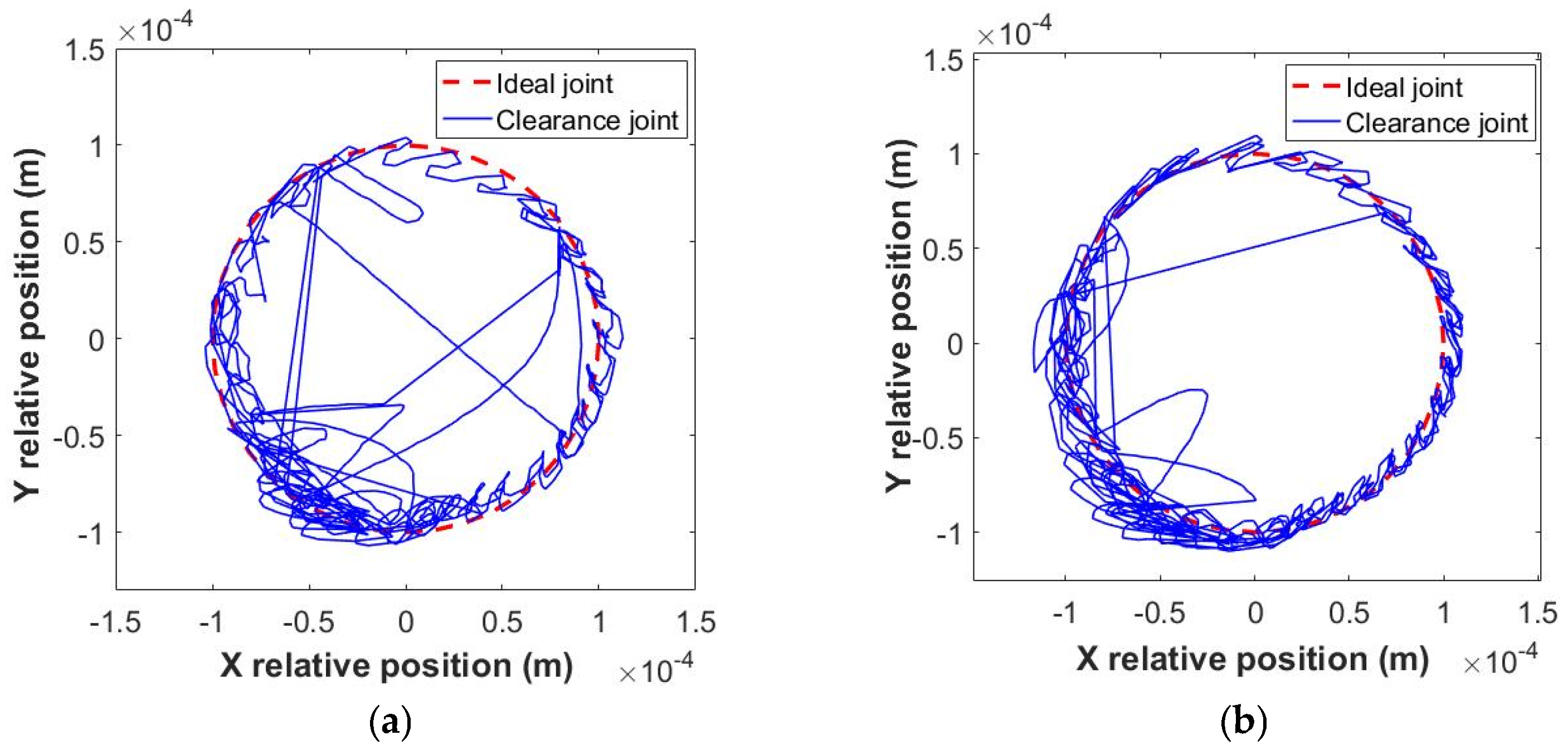
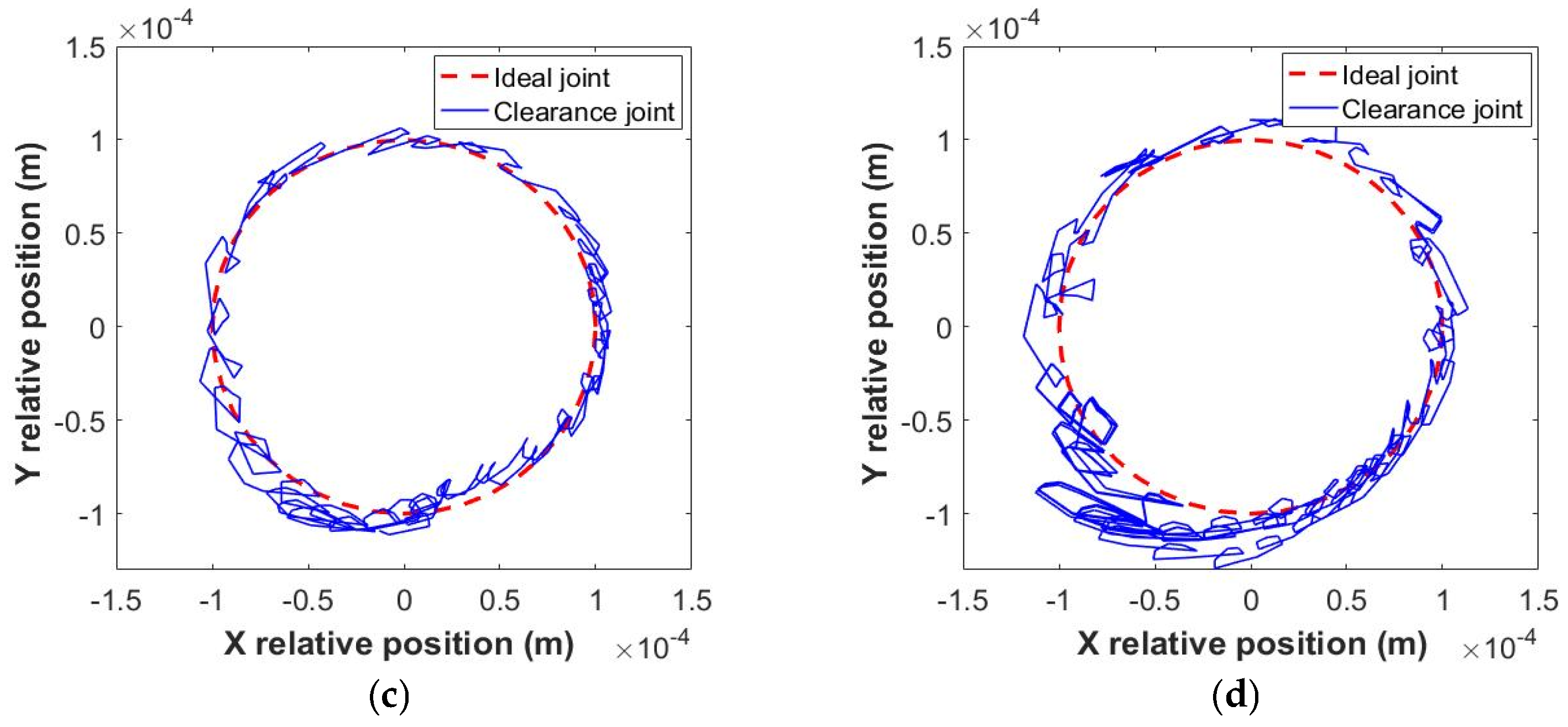
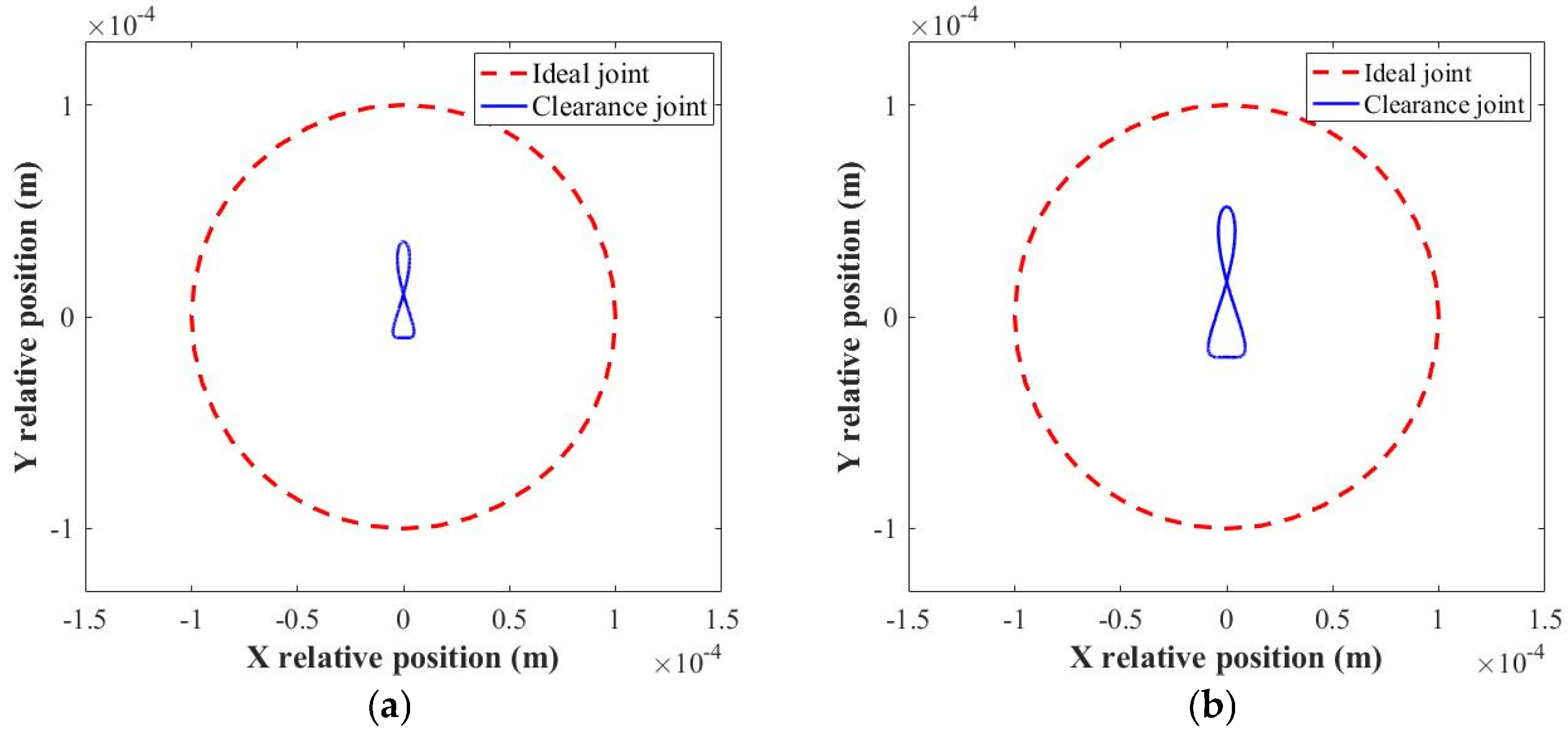
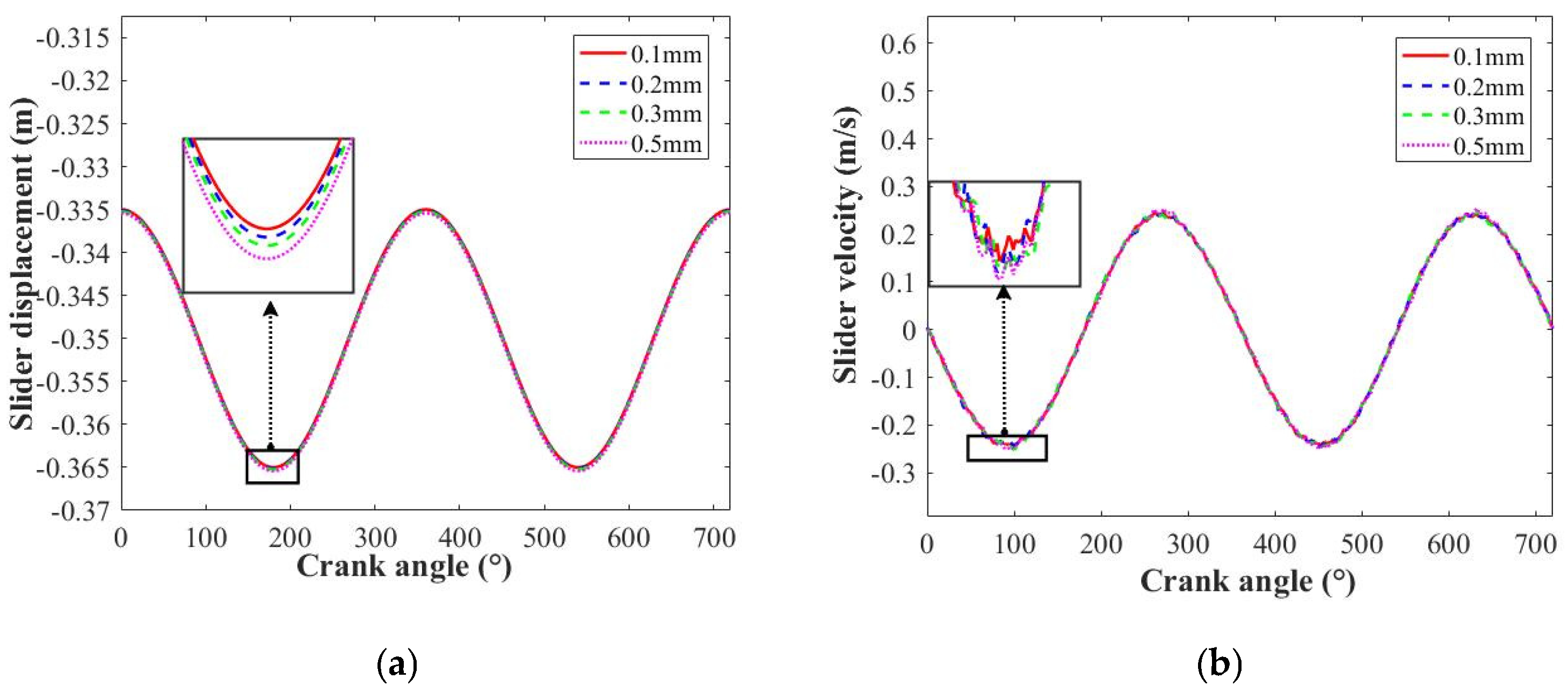
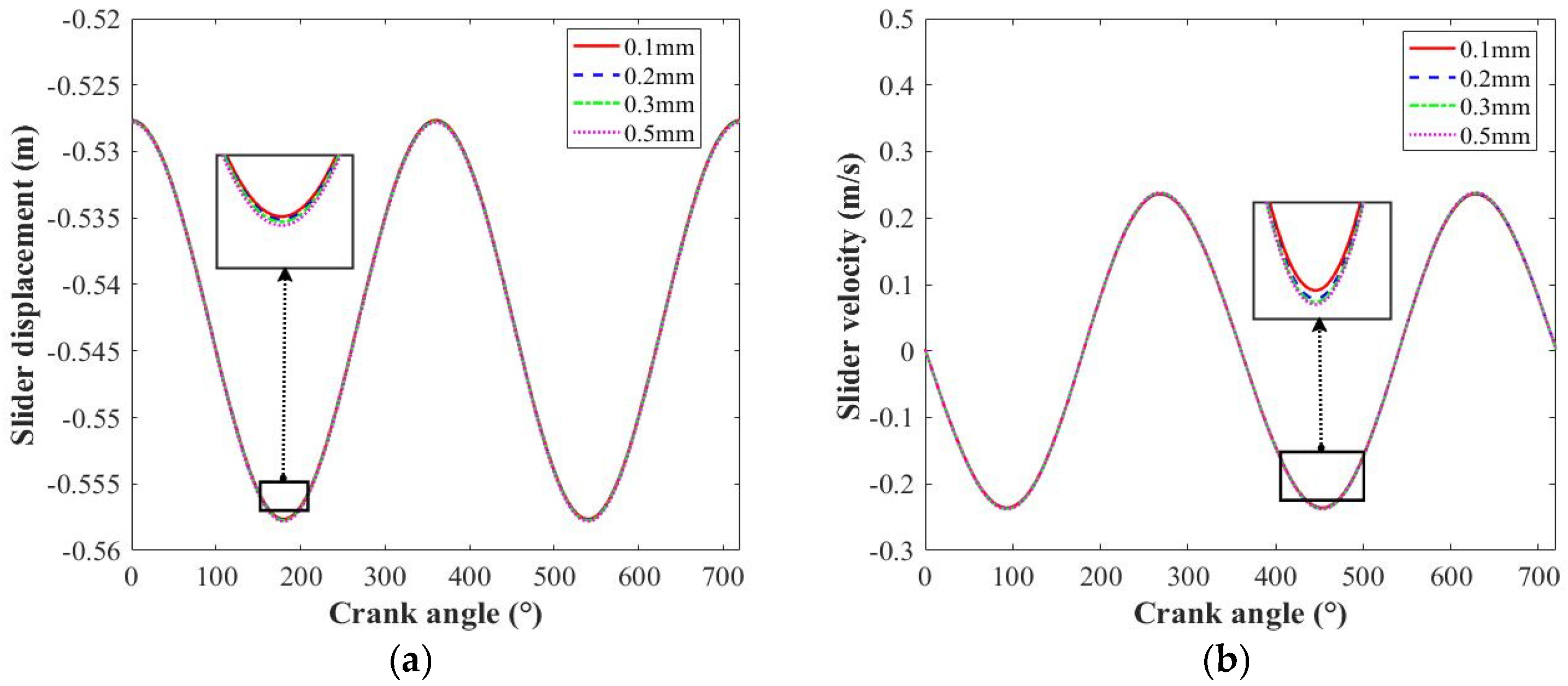
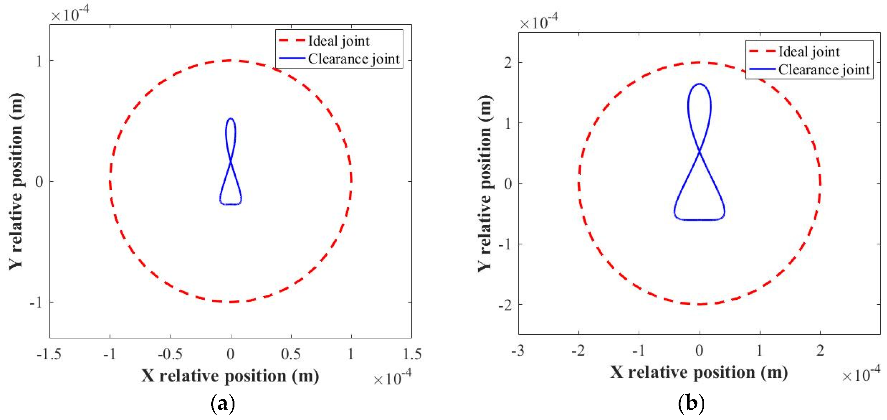
4.2. Influence of Clearance Size

The clearance size is closely related to the kinematic feature of the mechanism, and it is one of main parameters for the design of a mechanism with a clearance joint. With the same rotation speed (150 rpm), the clearance size is defined as variable (0.1 mm, 0.2 mm, 0.3 mm, 0.5 mm). Then, the effects of clearance size on the dynamic response of the slider crank mechanism under different lubrication conditions are discussed.
Figure 11 presents the influence of the clearance joint on the dynamic behavior of the slider crank mechanism under dry contact conditions. Compared with the working condition effects, the degree of coincidence of the slider displacement with different clearance sizes cannot be found. The obvious deviation appears in the motion trajectory of the slider, which means that the expected route is changed by the clearance. The slider velocity could reflect this phenomenon clearly, as well as the intense vibration in the bottom point of the slider velocity. The data indicate that contact impact frequency and complex motion transmission occur in the clearance joint. Figure 12 displays the slider acceleration of the mechanism with different clearance sizes. Notably, when the clearance size exceeds 0.3 mm, the contact phenomenon and vibration characteristics experience significant growth throughout the whole motion period. It is well known that increasing the clearance size enhances the movement space of the journal, which, in turn, affects the contact parameters and subsequently the vibration frequency and peak value.
Figure 13 shows the joint center trajectory under the dry contact condition, and the kinematic feature of the clearance joint is more sensitive to variations in clearance size. The motion state, closely associated with the movement space produced by clearance, also plays a critical role. Compared to the influence of the working condition, the free movement state of the clearance joint can be found under different clearance sizes conditions. Beyond a clearance size of 0.2 mm, the free movement state is obviously enhanced. The results show that the activity of the clearance joint is improved in the larger clearance size condition. Additionally, the penetration value of the contact impact is also enlarged.
Compared with the dry contact condition, the lubrication improves the stability of the motion trajectory and the contact impact phenomenon is probably better (Figure 14 and Figure 15). The deviation in the slider displacement can be decreased for the different clearance sizes, which also suggests that the motion range would be controlled. The liquid medium is filled with the movement space of the clearance joint, and the eccentricity of the joint element centers extrudes the oil film, which is the reason why the supporting force of the lubricant medium appears. Then, the fluctuation in slider velocity and acceleration is restrained by the lubrication medium. However, the obvious deviation in slider acceleration is found in the larger clearance size (0.5 mm), which means unpredictable motion trajectory of the mechanism at the larger clearance size.
Figure 16 plots the center trajectory of the clearance joint under lubrication conditions. With the introduction of lubrication characteristics, the motion instability and nonlinear dynamics in the center trajectory are minimal, especially with a smaller clearance size. When the clearance size exceeds 0.3 mm, the motion trajectory moves to the boundary outline. Although the motion range increases, the motion trajectory of the slider crank mechanism cannot be chaotic. Then, the regularity and periodicity of motion are presented.

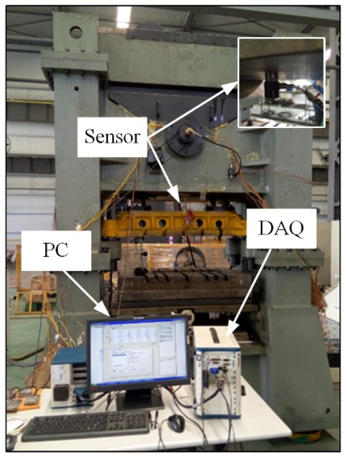
5. Experimental Test

The experimental platform of planar mechanical systems is built in a press machine, and a slider is employed for the execution unit shown in Figure 17. The kinematic accuracy of mechanical systems is used to determine the manufacturing quality. A dynamic stability test (acceleration) is conducted, and test data are collected using the data acquisition card (DAQ).
The influence of lubrication characteristics on the dynamic response of the transmission mechanism with the clearance joint is evaluated. Figure 18 displays the slider acceleration at different working speeds. The results show that the variation in slider acceleration with different lubrication characteristics is more sensitive. The increase in lubrication characteristics could restrain the vibration amplitude of contact impact, which is consistent with the content presented in the simulation. This phenomenon is attributed to the fact that changes in oil film pressure affect the supporting force.

6. Conclusions

In this study, the nonlinear dynamics of a slider crank mechanism with a clearance joint are thoroughly analyzed. A dynamic model of the clearance joint is modeled by considering actual factors, including contact characteristics, energy loss, and lubrication. The modelling approach for a planar mechanical system is presented, and the lubricated characteristics are introduced into the revolute joint. This case study represents the extensive engineering application of high-precision mechanism design.
Furthermore, this study explores the dynamic response of the mechanism with a clearance joint under various conditions. The coupled effects of lubrication characteristics, clearance size, and working parameters are shown to influence the center trajectory of the clearance joint and the dynamic stability in detail. The vibration response and motion velocity are significantly affected by the clearance joint. Similarly, the values of the contact period and penetration for the clearance joint vary markedly with different working conditions. Changes in the lubrication characteristics directly impact the slider acceleration. Additionally, the center trajectory is found to be sensitive to the structural parameters and working conditions. The proposed method provides effective recommendations for the optimization and design of high-precision mechanisms.
In addition, the proposed method can be expanded to stability analysis of mechanical systems, and the lubricated clearance joint is indispensable in engineering. For example, the multi-link mechanism is employed in press machines, and the transmission mechanism is used in satellite deployment boards.

Author Contributions

Methodology, X.P.; Software, Y.G.; Validation, H.Z.; Writing—original draft, X.W.; Writing—review & editing, Y.C. All authors have read and agreed to the published version of the manuscript.

Funding

This work was supported by the China Postdoctoral Science Foundation (No. 2020M681531).

Data Availability Statement

The original contributions presented in this study are included in the article. Further inquiries can be directed to the corresponding author.

Conflicts of Interest

The authors declare no conflict of interest.

References

  1. Yan, S.Z.; Guo, P. Kinematic accuracy analysis of flexiblemechanisms with uncertain link lengths and joint clearances. Proc. Inst. Mech. Eng. Part C J. Mech. Eng. Sci. 2011, 225, 1973–1983. [Google Scholar] [CrossRef]
  2. Muvengei, O.; Kihiu, J.; Ikua, B. Dynamic analysis of planar multi-body systems with LuGre friction at differently located revolute clearance joints. Multibody Syst. Dyn. 2012, 28, 369–393. [Google Scholar] [CrossRef]
  3. Farahan, S.B.; Ghazavi, M.R.; Rahmanian, S. Bifurcation in a planar four-bar mechanism with revolute clearance joint. Nonlinear Dyn. 2017, 87, 955–973. [Google Scholar] [CrossRef]
  4. Lai, X.M.; Lai, Q.F.; Huang, H. New approach to assess and rank the impact of revolute joint wear on the kinematic accuracy in the low-velocity planar mechanism. Adv. Eng. Softw. 2016, 102, 71–82. [Google Scholar] [CrossRef]
  5. Farahanchi, F.; Shaw, S.W. Chaotic and periodic dynamics of a slider-crank mechanism with slider clearance. J. Sound Vib. 1994, 177, 307–324. [Google Scholar] [CrossRef]
  6. Skrinjar, L.; Slavic, J.; Boltezar, M. A validated model for a pin-slot clearance joint. Nonlinear Dyn. 2017, 88, 131–143. [Google Scholar] [CrossRef]
  7. Sun, J.L.; Tian, Q.; Hu, H.Y. Topology optimization based on level set for a flexible multibody system modeled via ANCF. Struct. Multidiscip. Opt. 2017, 55, 1159–1177. [Google Scholar] [CrossRef]
  8. Zheng, E.L.; Fan, Y.D.; Zhu, R.; Zhu, Y. Prediction of the vibration characteristics for wheeled tractor with suspended driver seat including air spring and MR damper. J. Mech. Sci. Technol. 2016, 30, 4143–4156. [Google Scholar] [CrossRef]
  9. Zhao, Q.Q.; Guo, J.K.; Hong, J. Analysis of angular errors of the planar multi-closed-loop deployable mechanism with link deviations and revolute joint clearances. Aerosp. Sci. Technol. 2019, 87, 25–36. [Google Scholar] [CrossRef]
  10. Guo, H.N.; He, P.; Liu, Z.S. Investigation of an improved planar revolute joint contact model with rough surface. Tribol. Int. 2019, 134, 385–393. [Google Scholar] [CrossRef]
  11. Erkaya, S. Trajectory optimization of a walking mechanism having revolute joints with clearance using ANFIS approach. Nonlinear Dyn. 2013, 71, 75–91. [Google Scholar] [CrossRef]
  12. Bai, Z.F.; Zhao, Y. A hybrid contact force model of revolute joint with clearance for planar. Int. J. Nonlinear Mech. 2013, 48, 15–36. [Google Scholar] [CrossRef]
  13. Bai, Z.F.; Sun, Y. A study on dynamics of planar multibody mechanical systems with multiple revolute clearance joints. Eur. J. Mech. A/Solid 2016, 60, 95–111. [Google Scholar] [CrossRef]
  14. Zheng, X.D.; Zhang, F.; Wang, Q. Modeling and simulation of planar multibody systems with revolute clearance joints considering stiction based on an LCP method. Mech. Mach. Theory 2018, 130, 184–202. [Google Scholar] [CrossRef]
  15. Li, X.; Ding, X.L.; Chirikjian, G.S. Analysis of angular-error uncertainty in planar multiple-loop structures with joint clearances. Mech. Mach. Theory 2015, 91, 69–85. [Google Scholar] [CrossRef]
  16. Muvengei, M.; Kihiu, J.; Ikua, B. Effects of clearance size on the dynamic response of planar multi-body systems with differently located frictionless revolute clearance joints. J. Energy Technol. Policy 2012, 2, 7–18. [Google Scholar]
  17. Rahmanian, S.; Ghazavi, M.R. Bifurcation in planar slider-crank mechanism with revolute clearance joint. Mech. Mach. Theory 2015, 91, 86–101. [Google Scholar] [CrossRef]
  18. Li, Y.Y.; Wang, C.; Huang, W.H. Dynamics analysis of planar rigid-flexible coupling deployable solar array system with multiple revolute clearance joints. Mech. Syst. Signal Process. 2019, 117, 188–209. [Google Scholar] [CrossRef]
  19. Li, Y.Y.; Wang, Z.; Wang, C. Effects of torque spring, CCL and latch mechanism on dynamic response of planar solar arrays with multiple clearance joints. Acta Astronaut. 2017, 132, 243–255. [Google Scholar] [CrossRef]
  20. Flores, P.; Leine, R.; Glocker, C. Modeling and analysis of planar rigid multibody systems with translational clearance joints based on the non-smooth dynamics approach. Multibody Syst. Dyn. 2010, 23, 165–190. [Google Scholar] [CrossRef]
  21. Zhao, B.; Zhang, Z.N.; Fang, C.C.; Dai, X.D.; Xie, Y.B. Modeling and analysis of planar multibody system with mixed lubricated revolute joint. Tribol. Int. 2016, 98, 229–241. [Google Scholar] [CrossRef]
  22. Zhao, B.; Zhou, K.; Xie, Y.B. A new numerical method for planar multibody system with mixed lubricated revolute joint. Int. J. Mech. Sci. 2016, 113, 105–119. [Google Scholar] [CrossRef]
  23. Flores, P.; Lankarani, H.M. Dynamic response of multibody systems with multiple clearance joints. J. Comput. Nonlinear Dyn. 2012, 7, 031003. [Google Scholar] [CrossRef]
  24. Daniel, G.B.; Cavalca, K.L. Analysis of the dynamics of a slider–crank mechanism with hydrodynamic lubrication in the connecting rod–slider joint clearance. Mech. Mach. Theory 2011, 46, 1434–1452. [Google Scholar] [CrossRef]
  25. Chen, X.L.; Jia, Y.T. Dynamic modeling and responses investigation of spatial parallel robot considering lubricated spherical joint. Eur. J. Mech. A/Solid 2022, 92, 104458. [Google Scholar] [CrossRef]
  26. Jin, G.G.; Wang, Z.M.; Liang, D. Modeling and dynamics characteristics analysis of six-bar rocking feeding mechanism with lubricated clearance joint. Arch. Appl. Mech. 2023, 93, 2831–2854. [Google Scholar] [CrossRef]
  27. Song, N.N.; Peng, H.J.; Kan, Z.Y. Nonsmooth strategy for rigid-flexible multibody system considering different types of clearance joints and lubrication. Multibody Syst. Dyn. 2022, 55, 341–374. [Google Scholar] [CrossRef]
  28. Li, Y.Y.; Yang, Y.; Li, M. Dynamics analysis and wear prediction of rigid-flexible coupling deployable solar array system with clearance joints considering solid lubrication. Mech. Syst. Signal Process. 2022, 162, 108059. [Google Scholar] [CrossRef]
  29. Xu, L.X.; Yang, Y.H. Modeling a non-ideal rolling ball bearing joint with localized defects in planar multibody systems. Multibody Syst. Dyn. 2015, 35, 409–426. [Google Scholar] [CrossRef]
  30. Ping, T.; Zhang, Y.Q. Simulation of planar mechanisms with revolute clearance joints using the multipatch based isogeometric analysis. Comput. Methods Appl. Mech. Energy 2019, 343, 453–489. [Google Scholar]
  31. Zhao, Y.; Bai, Z.F. Dynamics analysis of space robot manipulator with joint clearance. Acta Astronaut. 2011, 68, 1147–1155. [Google Scholar] [CrossRef]
  32. Li, H.G.; Meng, G.; Meng, Z.Q.; Wen, B.C. Effects of boundary conditions on a self-excited vibration system with clearance. Int. J. Nonlinear Sci. Numer. Simul. 2007, 8, 571–580. [Google Scholar] [CrossRef]
  33. Bai, Z.F.; Chen, J.; Sun, Y. Effects of contact force model on dynamics characteristics of mechanical system with revolute clearance joints. Iran. J. Sci. Technol. Trans. Mech. Eng. 2014, 38, 375–388. [Google Scholar]
  34. Harsha, S.P.; Nataraj, C. Nonlinear dynamic response of high speed ball bearings due to surface waviness and unbalanced rotor. Int. J. Nonlinear Sci. Numer. 2006, 7, 163–166. [Google Scholar] [CrossRef]
  35. Xu, L.X.; Li, Y.G. Investigation of joint clearance effects on the dynamic performance of a planar 2-DOF pick-and-place parallel manipulator. Robot. Comput. Integr. Manuf. 2014, 301, 62–73. [Google Scholar]
  36. Wang, J.Y.; Wang, H.T.; Wang, H.; Guo, L.X. Influence of random system parameters on the nonlinear dynamic characteristics of gear transmission system. Int. J. Nonlinear Sci. Numer. 2017, 18, 619–630. [Google Scholar] [CrossRef]
  37. Lankarani, H.M.; Nikravesh, P.E. A contact force model with hysteresis damping for impact analysis of multibody systems. J. Mech. Des. 1990, 112, 369–376. [Google Scholar] [CrossRef]
  38. Pérez-González, A.; Fenollosa-Esteve, C.; Sancho-Bru, J.L. A modified elastic foundation contact model for application in 3D models of the prosthetic knee. Med. Eng. Phys. 2008, 30, 387–398. [Google Scholar] [CrossRef]
  39. Zhuang, F.F.; Wang, Q. Modeling and analysis of rigid multibody systems with driving constraints and frictional translation joints. Acta Mech. Sin. 2014, 30, 437–446. [Google Scholar] [CrossRef]
  40. Tian, Q.; Sun, Y.; Liu, C.; Hu, H.Y.; Flores, P. Elastohydrodynamic lubricated cylindrical joints for rigid–flexible multibody dynamics. Comput. Struct. 2013, 114, 106–120. [Google Scholar] [CrossRef]
Figure 1. Model of revolute clearance joint: (a) contact impact state; (b) velocity vector of the contact point.
Lubricants 13 00124 g001
Figure 2. Model of a lubricated clearance joint.
Lubricants 13 00124 g002
Figure 3. Diagram of the mechanism with a clearance joint.
Lubricants 13 00124 g003
Figure 4. Solution of the mechanical system with a revolute clearance joint.
Lubricants 13 00124 g004
Figure 5. Motion trajectory of the mechanism under the dry contact condition (different rotation speeds): (a) slider displacement; (b) slider velocity.
Lubricants 13 00124 g005
Figure 6. Slider acceleration in the dry contact condition (different rotation speeds): (a) 120 rpm; (b) 150 rpm; (c) 180 rpm; (d) 200 rpm.
Lubricants 13 00124 g006
Figure 7. Joint center trajectory under the dry contact condition (different rotation speeds): (a) 120 rpm; (b) 150 rpm; (c) 180 rpm; (d) 200 rpm.
Lubricants 13 00124 g007aLubricants 13 00124 g007b
Figure 8. Motion trajectory of the mechanism under the lubrication condition (different rotation speeds): (a) slider displacement; (b) slider velocity.
Lubricants 13 00124 g008
Figure 9. Slider acceleration in the lubrication condition (different rotation speeds): (a) 120 rpm; (b) 150 rpm; (c) 180 rpm; (d) 200 rpm.
Lubricants 13 00124 g009
Figure 10. Joint center trajectory in the lubrication condition (different rotation speeds): (a) 120 rpm; (b) 150 rpm; (c) 180 rpm; (d) 200 rpm.
Lubricants 13 00124 g010aLubricants 13 00124 g010b
Figure 11. Motion trajectory of mechanism under the dry contact condition (different clearance sizes): (a) slider displacement; (b) slider velocity.
Lubricants 13 00124 g011
Figure 12. Slider acceleration under the dry contact condition (different clearance sizes): (a) 0.1 mm; (b) 0.2 mm; (c) 0.3 mm; (d) 0.5 mm.
Lubricants 13 00124 g012
Figure 13. Joint center trajectory under the dry contact condition (different clearance sizes): (a) 0.1 mm; (b) 0.2 mm; (c) 0.3 mm; (d) 0.5 mm.
Lubricants 13 00124 g013aLubricants 13 00124 g013b
Figure 14. Motion trajectory of the mechanism with lubrication (different clearance sizes): (a) slider displacement; (b) slider velocity.
Lubricants 13 00124 g014
Figure 15. Slider acceleration with lubrication (different clearance sizes): (a) 0.1 mm; (b) 0.2 mm; (c) 0.3 mm; (d) 0.5 mm.
Lubricants 13 00124 g015
Figure 16. Joint center trajectory under the lubrication condition (different clearance sizes): (a) 0.1 mm; (b) 0.2 mm; (c) 0.3 mm; (d) 0.5 mm.
Lubricants 13 00124 g016aLubricants 13 00124 g016b
Figure 17. Experiment platform of the press machine.
Lubricants 13 00124 g017
Figure 18. Slider acceleration of the experiment: (a) 120 rpm; (b) 150 rpm.
Lubricants 13 00124 g018
Disclaimer/Publisher’s Note: The statements, opinions and data contained in all publications are solely those of the individual author(s) and contributor(s) and not of MDPI and/or the editor(s). MDPI and/or the editor(s) disclaim responsibility for any injury to people or property resulting from any ideas, methods, instructions or products referred to in the content.

