Review

Additive Manufacturing of Advanced Structural Ceramics for Tribological Applications: Principles, Techniques, Microstructure and Properties

School of Materials Science and Engineering, Harbin Institute of Technology, Harbin 150001, China
*
Authors to whom correspondence should be addressed.
Lubricants 2025, 13(3), 112; https://doi.org/10.3390/lubricants13030112
Submission received: 7 January 2025 / Revised: 18 February 2025 / Accepted: 3 March 2025 / Published: 5 March 2025

Abstract

:
Additive manufacturing technology has the advantages of precise manufacturing, high levels of customization, and large-scale molding; it can achieve the design of complex geometric structures and structural/functional integrated components, which is difficult to realize using traditional manufacturing technology, especially for different tribological applications. Ceramic materials are widely used in industries such as high-end manufacturing in aviation, aerospace, energy, and biomedicine due to their excellent wear resistance, high temperature stability, and hardness. The tribological properties of ceramic parts determine their versatility and durability during the application process. The rise of additive manufacturing technology in the field of ceramics has opened up the possibility of creating ceramics with excellent friction and wear properties and overcoming the limitations of traditional manufacturing processes. Although several studies on 3D printing of wear-resistant/self-lubricating metal- or polymer-based parts have been published, there has until now been no comprehensive review of additive manufacturing of advanced structural ceramics and composites for the purpose of reducing friction and enhancing wear-resistant properties. This article discusses the currently used ceramic additive manufacturing technology and processes, the ceramic materials used in the field of tribology, and how the combination of these two can improve the tribological properties of ceramic components from the perspective of micro- and macrostructures. Finally, specific tribological applications of additively manufactured ceramics in various industrial and biomedical fields are also introduced.

1. Introduction

Friction, wear, and lubrication are phenomena that constantly occur on interacting surfaces in relative motion in nature. In industrial production and applications, friction and wear have complex effects on mechanical structures and physical and chemical characteristics of material contact surfaces. It is important to understand the nature of these interactions and solve the technological problems associated with interfacial contact. About 23% of the world’s total energy consumption comes from frictional contact, of which 20% is used to overcome friction, and 3% is used to remanufacture worn parts and spare equipment due to friction- and wear-related failures [1]. Advanced ceramic-based self-lubricating materials are expected to become promising candidates for use in high-temperature environments above 1000 °C due to their low specific density, good mechanical properties, and excellent oxidation resistance [2,3]. However, ceramic materials usually have relatively high friction coefficients and wear rates under the conditions of high temperatures and dry sliding wear, as well as heavy loads or high sliding speeds [4], which is not conducive to the stable and safe operation of equipment over long periods. Nowadays, humanity is facing challenges related to sustainable, ecological, and green development, and unnecessary friction and wear will have a harmful impact on industry. Therefore, it is crucial to promote the development and innovation of friction-reducing and wear-resistant materials and technologies.
Additive manufacturing (AM) technology has the advantages of complex structural design, rapid prototyping, the precise regulation of shapes/properties, etc.; it has been confirmed to be applicable to the production of structural/functional integrated parts using metals, polymers, ceramics or combinations of multi-materials [5,6,7,8,9]. The ultraviolet-light-assisted direct ink writing (DIW) method was used to produce polytetrafluoroethylene (PTFE)-polyimide architectures for tribological applications in aerospace, aviation, and microelectronics [9]. After post-heat treatment, the 3D-printed PTFE-filled photosensitive polyimide bearing was effectively verified, and it exhibited excellent self-lubricating properties with a low friction coefficient of only 0.09 and a low wear rate [8]. Additive manufacturing technology has showcased bright application prospects in a variety of fields. It has received particular attention in tribology, in areas such as aviation, aerospace, energy, metallurgy, electronic industries, and biomedical implants. The manufactured parts include impellers, bearings, bushings, screws and nuts, blast nozzles, cutting tools, dental crown, implants, hip prostheses, bone tissue engineering, pumps, dies, valves, seals, and other rotatory or sliding tribo-components.
Although several studies on 3D-printing of wear-resistant/self-lubricating metal- or polymer-based parts have been published, no comprehensive review has yet been conducted on additive manufacturing of advanced structural ceramics and composites for the purpose of reducing friction and enhancing wear resistance. It is equally important that additively manufactured ceramic components treated with friction-reducing and anti-wear processes are good candidates for load-bearing applications under extreme working conditions such as high contact pressure, high sliding speeds, elevated temperatures, severe oxidation and chemical reactivity, and nuclear radiation environments. So far, AM-based ceramic parts with excellent friction and wear properties have been implemented [4,10,11,12,13]. Hence, the combination of 3D printing’s customizability and high precision with high-performance ceramic materials facilitates an innovative approach to the design and creation of lubrication structures. Interestingly, a variety of advanced structural materials such as circular-cored square/hexagonal honeycomb topologies, highly rigid 3D egg boxes, ‘lollipops’, inverted ‘Y’ structures, etc., can be 3D printed into tribological components for structural/functional integrated applications [14,15,16].

2. Ceramic Additive Manufacturing Technology and Process

Ceramic 3D printing technology and processes can be classified based on the nature of raw materials, the process involved, and the molding mechanism used. According to the ASTM/ISO 52900:2021 standard for additive manufacturing technologies, the methods are divided into seven categories: material extrusion, material jetting, barrel photopolymerization, powder bed fusion, sheet lamination, directed energy deposition, and binder jetting [17]. Similarly, Sun et al. [18] classified ceramic additive manufacturing processes into four main types based on the inherent formation mechanisms of various additive manufacturing technologies: extrusion-based technology, photopolymerization-based technology, powder-fusion-based technology, and powder-bonding-based technology. Therefore, the advantages and limitations of these technologies are summarized in Table 1.

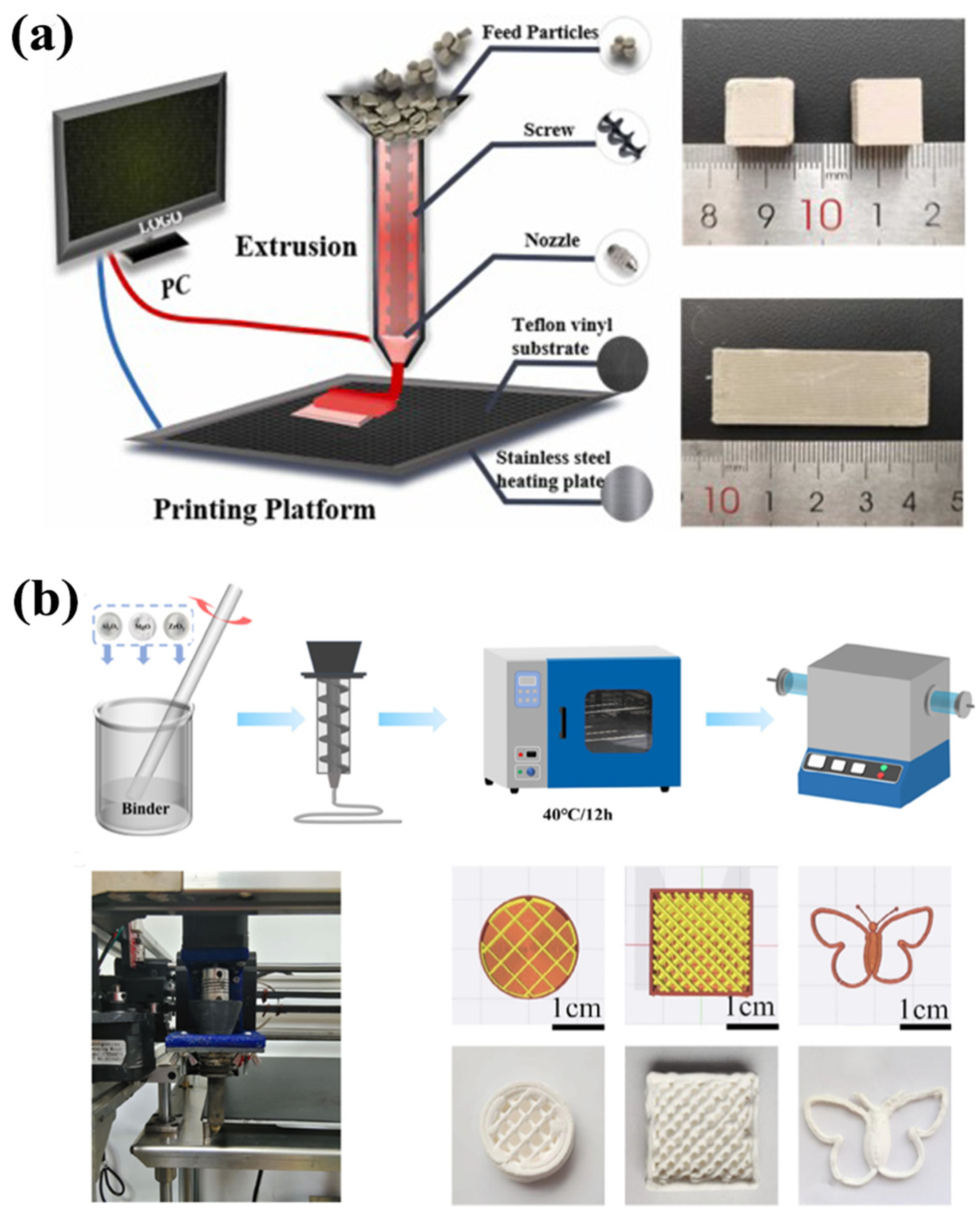
2.1. Ceramic 3D Printing Technology Based on Extrusion Molding Mechanisms

Extrusion molding refers to the process of extruding a fluid ceramic material paste through a nozzle of a certain caliber in a continuous flow method to form an ideal geometric shape, thereby forming and producing ceramic parts [45]. It is divided into two methods according to the nozzle design, the deposition characteristics of the binder, and the extrusion mode of ceramic materials: fused deposition modelling (FDM) and DIW processes. At present, this process is the most commonly used additive manufacturing technology for composite ceramics due to its adaptability of combining multiple materials with ceramics. Three different processes are used to achieve the additive manufacturing of composite materials. The first method uses multiple separate nozzles to store a variety of different raw materials and switches the order during the printing process to achieve the formation of a multi-material structure [46]. The second method uses a single nozzle to adjust the feed switch of raw materials to control the ratio of different raw materials, which realizes the possibility of manufacturing ceramic multi-materials with functional gradients [12]. The third method involves pre-mixing before co-extrusion to selectively produce different raw materials [22].
Fused deposition modelling (or the fused deposition of ceramics), also known as fused filament manufacturing, builds parts layer by layer by selectively depositing molten material in a predetermined path. It uses thermoplastic resins in the form of filaments incorporated with different volume fractions of ceramic precursor or particles to form the final physical object [47] Currently, FDM is the most successful industrialized 3D printing technology, with the advantages of the low price of consumables, a simple and economical process, and high production efficiency.
When FDM is combined with ceramic materials, the polymer-derived ceramics route is also adopted, using pre-ceramic polymers as precursors of the target ceramics, providing molding capabilities through the molding technology of thermoplastic polymers, printing out ceramic green bodies in the FDM process, and then performing a debinding and sintering process to remove the polymer components to obtain the final ceramic products. In fact, because the viscosity and elasticity of pre-ceramic polymers can be adjusted and converted into filaments through melt extrusion, the consumables used can be spherical [19]. FDM can now produce SiC ceramic components with complex structures for use in high-temperature environments, as shown in Figure 1a [20].
The DIW process involves preparing polymers and other ingredients into liquid or semi-liquid sprayable substances and releasing the mixed substances onto the substrate through a nozzle or a pen-like dispenser [9,12]. The paste material is then extruded from the nozzle and quickly solidifies after deposition to form the desired 3D structure, as shown in Figure 1b. For the manufacturing of ceramic materials, it is necessary to consolidate them through an oven process after DIW printing. Compared with FDM, the raw ink materials are extruded at room temperature and have broad compatibility and high process flexibility, but the ceramic ink used must exhibit properties such as stability, viscoelasticity, and a high solid content in order to be continuously extruded from the nozzle without clogging [48]. Fan et al. [12] were able to control the material composition and its gradient by adjusting the relative flow rates of different slurries, and the prepared gears made of graphene/Al2O3 composites with a gradient mechanism, which had an excellent wear resistance.
The binder system of extrusion 3D printing requires a suitable debinding process to remove it. Table 2 summarizes the binder systems and debinding processes involved in FDM and DIW. Wax-based binder system is used as a ceramic skeleton binder. In ceramic additive manufacturing, thermal debinding is required to eliminate these binders [49]. Kong et al. [20] performed thermal debinding on SiC blanks printed by extrusion with a wax-based binder. Chen et al. [50] performed thermal debinding on FDM-printed zirconia and found that the hardness and flexural strength of the sintered parts were 1486 ± 87 HV and 495 ± 11.8 MPa, respectively.
Moreover, solvent debinding is a kind of debinding process that uses solvents such as n-heptane, trichloroethane, and dichloromethane [51] to remove small molecular weight binders of paraffin and stearic acid. It has the advantages of avoiding partial shape defects and reducing the total debinding time. Many efforts have been made to combine these two to use a step-by-step debinding process, in which interconnected pore paths are formed during the solvent debinding process; this helps the decomposition gas produced by the pyrolysis of the remaining binder to be discharged from the part followed by the thermal debinding process. Liu et al. [21] used a two-step debinding method for solvent debinding and thermal debinding to remove the wax-based binder of FDM-printed cubic boron nitride using n-heptane. The bending strength and hardness of the sintered cBN samples reached maximum values of 1000.1 MPa and 4221.5 HV at a sintering temperature of 1500 °C. Lim et al. [52] used a mixed solvent debinding method of cyclohexane and ethanol, as well as a combined method of thermal debinding to degrease a green zirconia body based on screw-extrusion 3D printing. The sintered specimens that underwent this debinding method had a density of 97.5%, a Vickers hardness of 12.3 GPa, and a fracture toughness of 5.5 MPa·m1/2.
Since solvent debinding mostly uses various toxic and polluting organic solvents, catalytic debinding or water-based binder systems are selected. Yi et al. [53] conducted catalytic debinding on NiFe2O4-Cu-20Ni metal–ceramic and polyoxymethylene (POM)-based binder composite samples. At 120 °C, POM can be rapidly decomposed into formaldehyde in an acidic atmosphere. The optimal average flexural strength of the sintered NiFe2O4-based composite sample is 173.5 MPa, which is close to that (178.4 MPa) of the sample produced by traditional injection molding. Sarraf et al. [54] developed a mixture of ethylene vinyl acetate (EVA) and polyvinyl alcohol (PVA) as a binder for environmental protection, which could be successfully treated by solvent debinding in water.

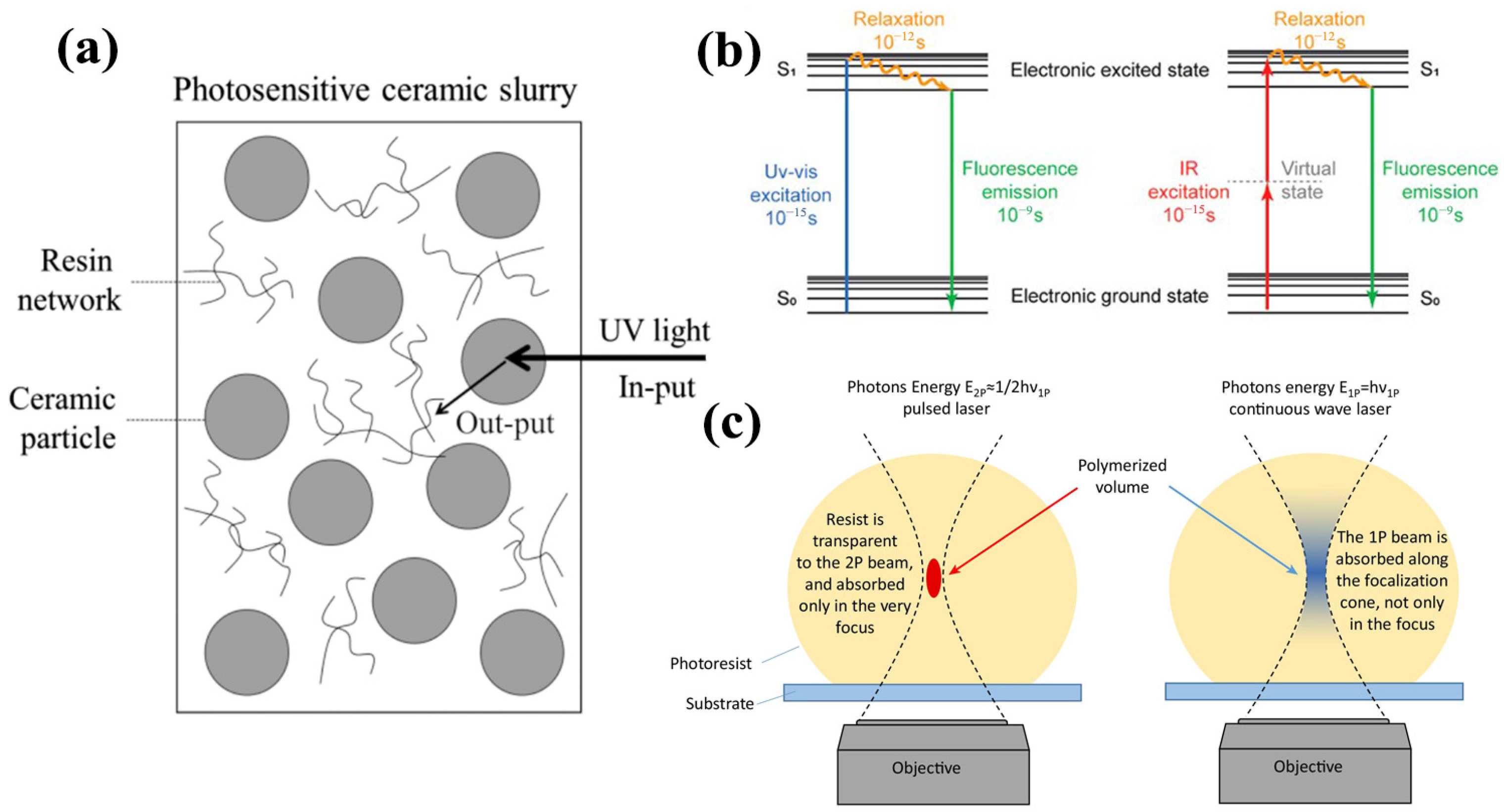
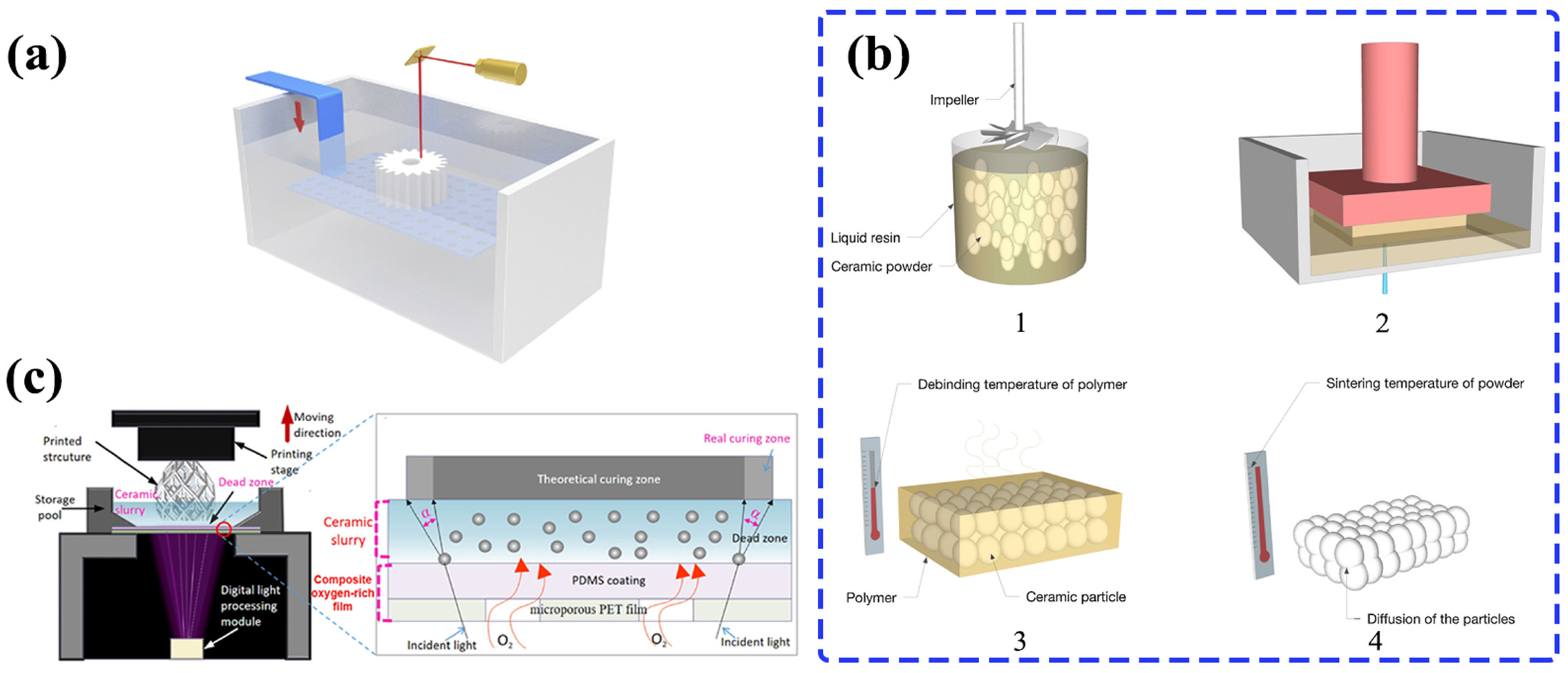
2.2. Ceramic 3D Printing Technology Based on Photopolymerization Mechanisms

Ceramic additive manufacturing based on photopolymerization uses a ceramic resin slurry system or a polymer ceramic precursor (pre-ceramic polymer, PCP) as the raw material in the fluid photosensitive liquid system. Photopolymerization, also known as photocuring, refers to the phenomenon whereby, when polymer monomers are exposed to light of a specific wavelength, a cross-linking polymerization reaction is initiated to solidify the liquid resin [55,56]. As shown in Figure 2a, in the ceramic resin slurry system, the photosensitive resin is cross-linked and polymerized to form a network structure that wraps the ceramic powder particles, making them dispersed and forming a solid ceramic polymer [57]. According to the type of light used in photopolymerization, as well as the process parameters and equipment, there are three kinds of printing technologies: stereolithography (SLA) [58], digital light processing (DLP) [59] and two-photon polymerization (TPP) [60,61]. The subsequent post-processing process, including thermal debinding and sintering, removes organic resin components and densification, which is similar to the sol–gel injection molding process for producing ceramic manufacturing methods. This section focuses on the development of the SLA, DLP, and TPP processes in the technology of ceramic additive manufacturing.
SLA technology was proposed and developed by C. Hull in 1986 and later commercialized by 3D Systems Co., Ltd. [58]. SLA is a process that uses a light source of a specific wavelength (usually in the UV range) to selectively cure the surface of a liquid in a tank containing mainly photopolymerizable monomers and very small amounts of other additives (photoinitiators). DLP technology is similar to SLA in that it is based on the polymerization of photopolymerizable monomers by the absorption of single photons [59]. With the development of stereolithography, new nanofabrication technologies have emerged, including two-photon polymerization (TPP), which relies on TPA, a nonlinear optical phenomenon that was theoretically proposed by Göppert Mayer in 1931 and experimentally observed by Kaiser and Garrett 30 years after the advent of lasers [60,61]. As shown in Figure 2b,c, compared to traditional single-photon absorption, the molecule transitions from the ground state to the excited state when absorbing two photons instead of one photon. TPA can be divided into non-degenerate and degenerate cases. In the non-degenerate case, two photons are absorbed sequentially and there is a real intermediate state. In the degenerate case, two photons are absorbed simultaneously and there is a temporary virtual state. The probability of TPA is proportional to the square of the laser intensity (non-degenerate case) or proportional to the product of the intensities of the two laser beams (degenerate case) [62]. Therefore, TPA-based TPP is able to break the diffraction limit and show high resolution in the 3D printing of complex structures with feature sizes below 200 nm [62,63,64].
The photoactivated polymerization process (i.e., the liquid monomer becomes a solid resin) is typically performed on a point-to-line, line-to-layer, and then layer-by-layer basis, while the light is scanned across the liquid surface. When the polymerization of a layer is complete, the barrel or platform supporting the produced part falls and rises according to the thickness of the layer, depending on whether the 3D printing process is a bottom-up or top-down variety. Some devices require a scraper to smooth the liquid surface before printing the next layer. SLA is capable of manufacturing parts with high surface quality at a fine resolution of microns. A schematic diagram of a typical SLA technique is shown in Figure 3a [65].
The ceramic stereolithographic process is achieved by adding ceramic powder to a photocurable medium. Ceramic stereolithography (CSL) can be used to manufacture a variety of advanced ceramic parts with complex geometric shapes due to its high resolution [66]. CSL has made significant progress in recent years, enabling it to produce high-performance ceramic parts, such as those used in the extreme high-temperature and high-pressure environments of the aerospace industry [67].
Figure 2. Principle of photopolymerization: (a) light transmission between ceramic slurries [57], copyright (2019), with permission from the American Chemical Society. (b) One-photon and two-photon excitation [68], copyright (2020), with permission from the American Chemical Society. (c) One-photon and two-photon polymerization [69], copyright (2019), with permission from Elsevier.
Lubricants 13 00112 g002
Figure 3. Ceramic 3D printing technology based on photopolymerization mechanisms: (a) SLA diagram [65], copyright (2018), with permission from Elsevier. (b) Flow chart of the steps in the CSL process: 1. Preparation of a suitable photocurable ceramic suspension by mixing ceramic powder and photosensitive resin; 2. Printing ceramic parts; 3. Debinding and polymer removal; 4. Sintering the ceramic green body [66], copyright (2020), with permission from Elsevier. (c) Principle of ceramic 3D printing with a composite oxygen-rich film based on DLP [28], copyright (2021), with permission from Elsevier.
Lubricants 13 00112 g003
As shown in Figure 3b, the CSL process includes the following main steps: mixing ceramic powders with photosensitive resin, dispersing these ceramic powders evenly in the solution via high-speed stirring, preparing a high-solid-content-loading, low-viscosity ceramic slurry, and then directly curing the ceramic slurry layer by layer on a photocuring machine to obtain a blank ceramic part, which is then heated and debinded to remove the internal organic components, and finally sintering to obtain a densified ceramic part [66]. The ceramic photocuring slurry is composed of ceramic powders, a photocuring monomer, a photoinitiator, a dispersant, diluent, etc. The ceramic photocuring molding process has a fast-molding speed and a short production cycle. As long as the platform is large enough, multiple parts can be printed at the same time. The photocuring molding accuracy is ±0.01 mm, and the surface morphology of the parts is better than those produced using the traditional FDM process.
Compared with the raw resin, the addition of ceramic powder significantly increases the viscosity and light transmittance of the resin, making the processing of ceramic slurry more difficult [70,71]. The sedimentation and rheological properties of the slurry are key parameters in the 3D printing process. During the photocuring process, the slurry is mostly in a static state, so it is particularly important to inhibit the sedimentation of ceramic particles in the slurry. When the ceramic powder is precipitated in the resin medium, the sedimentation rate depends on the resistance of the medium to the ceramic particles. The resistance can be divided into pressure and friction resistances. Since the relative movement speed between the ceramic particles and the resin is low, the pressure resistance is low, and only the friction resistance needs to be considered [72]. Liu et al. [24] manufactured ZrO2-Al2O3 composite ceramic parts with an actual density of 3.75 g/cm3, a hardness of 14.1 GPa, and a fracture toughness of 4.05 MPa·m1/2 based on SLA-3D printing technology followed by debinding and sintering.
The difference between DLP and SLA is that its photopolymerization process relies on the digital light source of the imaging projector instead of the ultraviolet laser. DLP technology generally cures the photosensitive ceramic/resin composite slurry layer by layer through a projector that generates a cross-sectional light image with a wavelength of 405 nm [10]. Compared with the point-line surface layer-by-layer scanning printing process of SLA, the light projection speed of DLP improves the manufacturing efficiency of the ceramic photocuring process. At the same time, the ability to generate high-resolution images with a minimum size of less than 50 μm also improves the printing accuracy and resolution [73].
In order to solve the problem associated with the printed layers influencing the mechanical and tribological properties of the finished products, Zhang et al. [28] proposed a DLP-based continuous ceramic printing technology using a composite oxygen-rich membrane. A composite oxygen-rich membrane consisting of a microporous PET membrane and a PDMS coating was designed. The oxygen control inhibition effect and low surface energy ensured the appropriate dead zone thickness, as shown in Figure 3c [28]. The surface roughness of final printed product was only 0.127 μm.
TPP technology was first applied to photosensitive resins to produce simple 3D structures [74]. In 1997, Maruo et al. [75] used polyurethane acrylate resin to prepare a spiral structure with a diameter of 7 μm, demonstrating the feasibility of TPP in manufacturing complex 3D microstructures. The use of polymer materials to manufacture high-precision 3D structures has inspired the use of nanomanufacturing processes to manufacture ceramic components with complex 3D microstructures and nanoscale feature sizes. The TPP process has better micron-resolution processing capabilities than SLA, so it can be used to manufacture higher-precision ceramic parts.
Prediger et al. [37] used a high-resolution two-photon lithography to manufacture transparent polycrystalline magnesium aluminate spinel ceramic structures with micron-level resolution. After debinding, sintering, and hot isostatic pressing, a transparent spinel ceramic with a surface roughness (Sq) of 10 nm and a minimum feature size of less than 13 μm was obtained. Chai et al. [38] used a femtosecond laser and two-photon polymerization to manufacture 3D ceramic green bodies, aiming to form a high-quality 3D glass-ceramic microstructure from a continuous -Si-O-Si-O-Zr-O- inorganic skeleton. After sintering, a three-dimensional microcrystalline glass nanolattice glass ceramic with perfect integrity and a smooth surface was obtained. This technology is highly important for the production of microstructured ceramics for wear-resistant optic devices, photonics or photocatalysis, and tribological applications. After printing the ceramic green body, it needs to be heat treated to obtain pure ceramic parts. First, it is necessary to determine the appropriate thermal debinding curve to remove the organic phase (binder) in the green body. During the process, both high shrinkage and rapid gas generation should be avoided so that the final performance of the product will not be reduced.
Table 3 shows the slurry systems and corresponding debinding processes for photopolymerization 3D-printing ceramics. Thermal debinding is the most commonly used debinding method, which utilizes the oxidation or pyrolysis of organic matter at high temperatures. Therefore, it is also divided into air debinding and vacuum or inert atmosphere debinding. In order to determine the appropriate debinding temperature and remove the resin without generating defects, the weight loss is monitored by thermogravimetry/differential scanning calorimetry (TGA-DSC). The photosensitive resins used, such as HDDA, TMPTA and DCPDA, have a debinding temperature of 300–500 °C in an air atmosphere [29].
The sintering process requires heating the debinded ceramic to a necessary sintering temperature, and eliminating the pores in the component through shrinkage to obtain a high-density ceramic component [33].

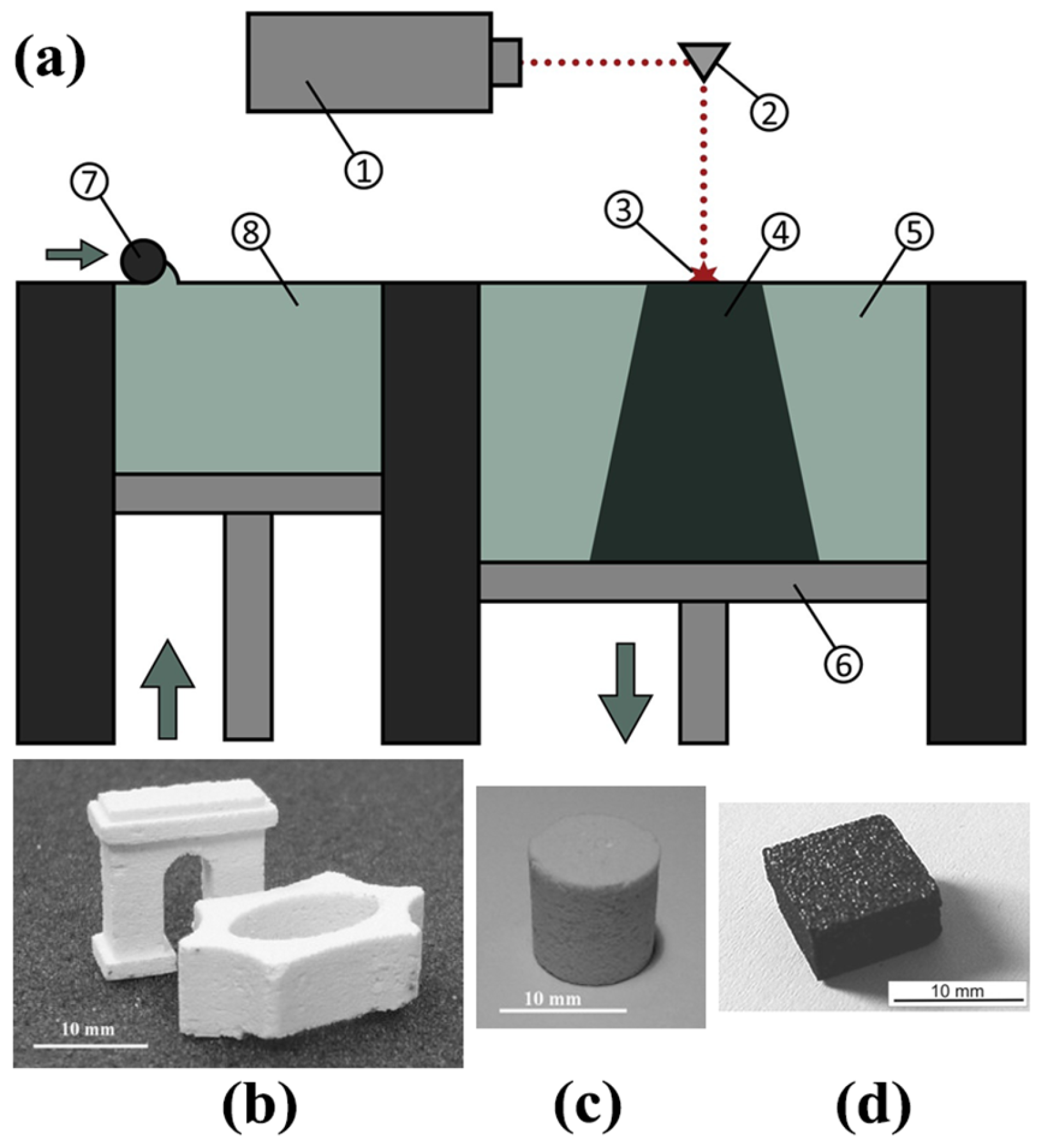
2.3. Ceramic 3D Printing Technology Based on a Powder Melting Mechanism

Ceramic additive manufacturing technology based on powder melting mechanisms uses a high-power laser beam or electron beam as a heat source. During the powder bed spreading process, a powder bed of various materials, including loose ceramic particles, is selectively melted or sintered to solidify into a finished product, as shown in Figure 4a [76]. Depending on whether the powder bed is melted or directly sintered and solidified, this is divided into two processes: selective laser melting (SLM) and selective laser sintering (SLS).
An important factor affecting the microstructure and mechanical properties of SLM products in the SLM process concerns the properties of the ceramic powder (in addition to their composition and purity, morphology, size, and uniformity of size distribution). Compared with irregularly shaped powders, samples made from granular powders have higher density and less porosity and defects [77]. The high-temperature melting mechanism of SLM/SLS is compatible with metal materials, which makes this process applicable to the AM production of a variety of metals, ceramics, and multi-materials. In addition, some researchers use various coating technologies such as magnetron sputtering, cold-spray, chemical vapor deposition (CVD), and other processes to form a thin metal layer on the ceramic powder to achieve the uniform distribution of metal binder in the ceramic powder and surface modification of the ceramic powder [40,78]. Shishkovsky et al. [39] produced ZrO2 ceramic samples using the SLM process (Figure 4b).
The multi-material adaptability of SLM/SLS enables it to be used to make ceramic composite materials. Multiple-material laser powder bed melting technology can be achieved by pre-mixing or adding a hopper. Shishkovsky et al. [39] made a mixture of ZrO2 and Al into ZrO2-Al2O3 composite ceramics by converting molten Al into Al2O3 during the SLS process (Figure 4c). Davydova et al. [40] verified the use of SLM process to make B4C/Co metal ceramics (Figure 4d).
Compared with extrusion-based and light-curing additive manufacturing technologies, the SLM and SLS processes can be used to obtain finished products without the post-processing of ceramics (debinding and sintering), but the surface roughness and printing accuracy are relatively low.

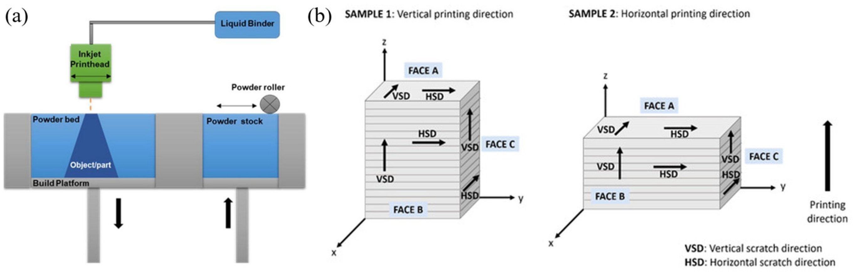
2.4. Ceramic 3D Printing Technology Based on the Powder Bonding Mechanism

Binder jet 3D printing (BJP) is similar to the SLM and SLS processes. It is based on a powder bed system and requires high-flowability powders with a D50 particle size in the range of 20–50 μm, but smaller spherical particles can be printed depending on the flowability [79]. Currently, the BJT process is relatively mature in terms of shaping the products of metals and polymers, but it lags behind in the field of ceramic materials. For example, the instruments used to produce sand molds and cores for metal casting have a low green density for producing ceramic materials [80]. The layers formed by depositing fine dry powders usually reach a packing density of less than 50% of the theoretical density. Fine particles also struggle to achieve flowability. These factors together hinder densification during sintering. Therefore, layer-wise slurry deposition (LSD) technology has been developed for the purposes of shaping the products of ceramic materials. It is based on spreading ceramic slurry through a scraper instead of using dry powder, as in traditional processes. Each deposited layer is then dried and printed with a high-packing-density powder layer using a print head. The equipment used is shown in Figure 5 [81,82]. Material jetting technology is a process similar to BJP; it combines ceramic powder with building material to form a depositable ink. It has a higher resolution but limited material selection (mostly zirconium oxide, aluminum oxide, etc.).
The LSD process uses an alginate binder system to prepare ceramic slurries, in which sodium alginate is a linear copolymer composed of blocks of b-D mannuronic acid (M) and a-L-guluronic acid (G) residues. When divalent ions are added to the G-block-rich sodium alginate for cross-linking, strong and brittle gels can be formed [83]. Zocca et al. [42] processed submicron Al2O3 powders based on the LSD printing process, selecting Cu2+ as the cation for alginate cross-linking; they produced samples with a density comparable to that of standard pressed samples (both in the green and after sintering).
The binder system of BJP needs to be removed via an appropriate debinding process, as shown in Table 4. Unlike other additive manufacturing processes used for ceramic materials, the BJP process using an alginate binder system contains only 0.3 wt.% of the total slurry, so debinding can be achieved by simply rinsing with deionized water. Although the parts have good clarity and surface quality after cleaning, the colloidal state limits the minimum size of the printed features. According to some results for Al2O3 produced using the binder jetting process, the relative density after sintering is 58.0–62.5% [42]. Huang et al. [44] obtained ZrO2 ceramic samples with a relative density of 50.99–54.27% after the solid-phase sintering of BJP-processed materials. Mylena et al. [84] prepared an aqueous suspension of 0.05 vol.% Ti3SiC2, 2 wt.% PEI, and 40 wt.% glycerol; they used the BJP process to manufacture MAX phase materials.

2.5. 4D Printing of Structural Ceramics

The 4D printing of structural ceramics is an advanced additive manufacturing technology based on 3D printing. It uses stimuli-responsive materials to create structures that can change shape in response to environmental stimuli (such as heat, light, humidity, water, chemicals, magnetic fields, etc.) in the fourth dimension of “time” [85,86]. 4D printing has significant potential in the highly efficient manufacturing of ceramic parts with complex structures.
Two methods are used to achieve ceramic 4D printing: one involves using anisotropic shrinkage during the sintering process to produce shape changes in the printed ceramic parts, which requires the sequential 3D printing of ceramic resins with different solid contents to achieve anisotropic shrinkage and shape changes during sintering [87]. The second method involves reshaping the 3D printed green body with the help of an external force or mold, and combining it with the subsequent sintering process [88]. For example, the 4D printing of elastomer-derived ceramics is achieved using DIW to manufacture YSZ ceramics [89].

3. Ceramic Materials Systems for Tribological Applications

Ceramic materials are often used as rotatory or sliding tribo-components in relative motion due to their excellent wear resistance and corrosion resistance. Scholars also verify their tribological properties using different additive manufacturing technologies to produce ceramic parts. Ceramic systems used in tribological applications are divided into oxide ceramics, non-oxide ceramics, bioceramics, MAX phases, and composite ceramics according to the property requirements of various ceramic materials.

3.1. Oxide Ceramics

The most widely used oxide ceramics are alumina and zirconia. According to the collected data, the process of sintering additive manufactured oxide ceramics and the corresponding mechanical properties are summarized in Table 5.

3.1.1. Al2O3

Alumina is the most widely used ceramic material in various industrial fields and it was the first ceramic material used for the study of additive manufacturing. Alumina ceramic powder is usually spherical and has good flowability, whether it is made into powder feedstock or slurry. It is involved in various ceramic 3D printing technologies. Badev et al. [90] conducted a systematic study on the photopolymerization kinetics of different ceramic suspensions; they found that, the lower the refractive index and absorption rate of the ceramic powder, the higher the photocuring efficiency. Since alumina has a low absorption rate and a low refractive index of ultraviolet rays, it is the most suitable ceramic material for additive manufacturing processes based on the photopolymerization effect.
When polymer additives are used, after additive manufacturing, the alumina ceramics need to undergo post-processing debinding and sintering. During the debinding stage, the oxide ceramics themselves are chemically stable products in an oxidizing atmosphere, so the debinding process does not need to be isolated from air contact. At the same time, debinding in an air atmosphere is also conducive to the oxidation of the carbon in organic components into gases such as CO and CO2, leaving them blank.
Al2O3 can be solid-state sintered to a high density in a temperature range of 1540 °C to 1650 °C, so no other sintering aids are generally required. It can also be used as a sintering aid for the sintering of other ceramic phases [26].

3.1.2. ZrO2

Due to their excellent fracture toughness, wear resistance, high temperature resistance, and biocompatibility, ZrO2 ceramics are widely used as structural and functional materials, such as grinding balls, heating tubes, artificial joint structures, and thermal protective coatings [22,44,91]. At present, zirconium oxide is mainly used as a material for preparing crowns and implants in oral dentistry. Since zirconium oxide has good osteoconductivity, it is conducive to bone formation when it comes into contact with bone. In addition, zirconium oxide does not produce allergic reactions or change taste. As it is a frequent feature of dental and orthopedic applications, the tribological behavior of zirconium oxide has been widely investigated.
Zirconia-based ceramics can be stabilized in the tetragonal or cubic phase, depending on the dopant used (Y2O3, MgO), its concentration, and the heat treatment process. Zirconia is usually stabilized with 3 mol.% yttria, which converts into tetragonal zirconia and enhances mechanical properties and surface characteristics. Yu et al. [22] produced yttria-stabilized zirconia (YSZ) parts with smooth surfaces via extrusion 3D printing, with a relative density of 98.1%, a Vickers hardness of 11.52 ± 0.57 GPa, and a fracture toughness of 2.63 ± 0.2 MPa·m1/2. Huang et al. [44] used liquid glass to infiltrate into porous zirconia ceramics based on the BJT process and increased its relative density from 54.27% to 94.49%.
The excellent mechanical properties of sintered zirconia are related to the stress caused by the transformation of the tetragonal to the monoclinic phase and a toughening effect. The increase in volume during the transformation leads to the development of a compression zone, which shields the propagating crack tip, thereby inhibiting the further propagation of the crack and successfully improving the toughness [92].

3.2. Non-Oxide Ceramics

As typical non-oxide ceramics, silicon carbide and silicon nitride have excellent chemical stability and wear resistance, and they are widely used in tribological applications. Table 6 presents the sintering process and corresponding mechanical properties of non-oxide ceramics based on different additive manufacturing technologies.

3.2.1. SiC

SiC is a covalent bond compound. Both silicon and carbon atoms are tetravalent elements. The outermost layer contains four valence electrons. They adopt sp3 hybridization and share a sp3 hybrid orbital to form a covalent tetrahedral structure. The Si-C bonding energy is about 4.6 eV. This high bonding energy gives it excellent properties, such as good chemical stability, good heat resistance, high strength, a low thermal expansion coefficient, and a wide band gap [94]. SiC is widely used as a hot-section components in the field of aerospace due to its excellent high-temperature mechanical properties (toughness, high-temperature stability, and wear resistance); for instance, it is processed into turbine bearings, nozzles, and reflectors [26,95]. Many structural parts used in aircraft are subjected to high-speed aerodynamic friction from air or other objects, which requires better wear resistance, especially at elevated temperatures. In addition, many efforts have also been made to improve the toughness, high temperature resistance, and wear resistance of 3D-printed SiC ceramic parts by introducing various additive manufacturing technologies.
Cheype et al. [19] used a pre-ceramic polymer SMP-730, along with Si and SiC fillers, to manufacture 3D SiC based on the FDM process, which was able to achieve a quasi-net shape with a volume shrinkage of 9.1%. However, due to the accuracy of the FDM process, the printed part features were 400 μm. Kong et al. [20] studied SiC green bodies sintered at temperatures of 1200–1950 °C and noticed that the density of SiC was the highest at 1950 °C. In this case, the density, Vickers hardness, and three-point bending strength of the sintered SiC sample were 3.11 g/cm3, 19.35 ± 0.28 GPa and 225 ± 27 MPa, respectively. Ding et al. [26] used SLA combined with the PIP process to print SiC ceramic optical mirrors, with a final relative density of 93.5%, significantly improving the final density and strength of the product. When using ceramic additive manufacturing technology based on the photopolymerization mechanism, it is necessary to consider the high refractive index and light absorption rate of SiC. According to the measurement results of the Beijing Institute of Technology, the absorbance of SiC particles under a light source with a wavelength of 405 nm reaches 0.417. The higher the absorbance, the less light acts on the polymer network and the worse the curing ability [96]. Tang et al. [34] proposed introducing low-absorbency SiO2 fillers to reduce the absorbance of SiC slurry. Cao et al. [97] directly pre-oxidized the SiC raw powders to obtain a SiC@SiO2 core–shell form to reduce the ultraviolet light absorption rate. Guo et al. [98] used the tetraethyl orthosilicate (TEOS) sol–gel method to form a low-absorption, sparse, and porous SiO2 coating on the surface of the SiC powder through a non-uniform precipitation process.
The thermal debinding of non-oxide ceramics such as SiC, Si3N4 and B4C in an air atmosphere will lead to oxidation. Therefore, they generally undergo thermal debinding in a vacuum or inert atmosphere. The organic matter is converted into pyrolytic carbon (PRC) at high temperatures. For SiC ceramics, residual pyrolytic carbon can also react with the introduced SiO2 to obtain SiC [97].
The sintering of SiC ceramics produced by additive manufacturing is usually maintained at a temperature of 1500~1800 °C in an inert atmosphere, combined with the LSI process to obtain highly densified SiC ceramics [93,98]. The higher the relative density of SiC, the better the wear resistance. The liquid silicon infiltration (LSI) process introduces a molten Si phase into the porous green body after debinding, and the Si phase reacts with pyrolytic carbon to obtain SiC, further improving the relative density of the ceramic parts.

3.2.2. Si3N4

Si3N4 is a ceramic material with high hardness, high wear resistance, and excellent thermal shock stability and biocompatibility. It has been widely used in various fields, as objects such as ceramic cutting tools, bearing balls, artificial joints, turbo-rotors etc. [99,100]. However, due to the characteristics and molds of the traditional ceramic molding processes, it is very challenging to prepare Si3N4 ceramic parts with complex structures and large sizes. Additive manufacturing (AM) has emerged as a molding process that does not require molds and has high work efficiency and high molding accuracy [101]. The Young’s modulus and flexural strength of Si3N4 are as high as 310 GPa and 1.35 GPa, respectively, and the theoretical density is lower than that of many other ceramics, at only 3.20 g/cm3. Therefore, structural parts designed using 3D printing can maintain strength and wear resistance while being lightweight.
Huang et al. [27] manufactured porous honeycomb Si3N4 ceramic parts based on SLA technology, with a specific compressive strength of 681.7 MPa·cm3/g, which is higher than that of conventional manufacturing technologies, and the surface roughness was 1.327 μm, which is significantly lower than other manufacturing processes. Although Si3N4 has been shown to resist bacterial proliferation and induce bone regeneration, it is extremely difficult to prepare Si3N4 dental implants using traditional technologies. Zou et al. [36] prepared Si3N4 dental implants with a relative density of 98.50% based on DLP technology, and their mechanical properties are comparable to those of traditionally produced Si3N4 ceramics.
The densification of Si3N4 requires the addition of sintering aids (including Al2O3, Y2O3, MgO, and SiO2, etc.). High-temperature liquid phase sintering is beneficial to the promotion of densification at temperatures of 1650~1825 °C in an inert atmospheric environment [27,36,102].

3.3. Bioceramics

The chemical formula of hydroxyapatite (HAP) is Ca10(PO4)6(OH)2. It is a type of calcium phosphate ceramic. Its crystal structure is very similar to human bone tissue, which is why it has excellent biocompatibility with bone tissue [103]. At the same time, hydroxyapatite also has a good osteoconductivity, which is sufficient to form strong chemical bonds and mechanical interlocking with bones [104]. Therefore, it is necessary to investigate how to use 3D printing technology to manufacture artificial bones, artificial teeth, etc., and to further evaluate their tribological properties in simulated human environments. Table 7 shows the sintering process and corresponding mechanical properties of the collected bioceramics produced via 3D printing. Duan et al. [41] used carbonated hydroxyapatite to manufacture nanocomposite microspheres based on SLS technology, which have higher wear resistance than human bones. According to the results reported by Mohammadi et al. [30,105], the sintering temperature of the debinded hydroxyapatite samples is set between 1200 and 1300 °C, which ensures the high-density microstructure of the samples. Chen et al. [25] proved that the HAP samples based on 3D printing did not undergo chemical reactions during the sintering process, and a high-purity HAP was obtained, retaining its biocompatibility.
Fluorapatite (FAp) glass–ceramics are composed of a glass phase and a needle-like FAp crystal phase, with a crystal structure similar to that of enamel [106]. They have broad application prospects in dental restoration due to their high performance in terms of biocompatibility, aesthetic properties, and mechanical properties [106,107,108]. Yang et al. [108] prepared a new type of FAp microcrystalline glass sample via SLA-3D printing, which had a similar microstructure to and better mechanical properties than glass–ceramics prepared using the traditional dry pressing method.
Table 7. Sintering process and corresponding mechanical properties of bioceramics.
CompositionSintering
Process
Sintering
Parameter
Relative Density (%)Bending Strength
(MPa)
Compressive Strength
(MPa)
ModulusRef.
HAP-1200 or 1300 °C (1 h)98.0–98.9100--[30]
PLS 1 in Ar1250 °C----[25]
CHAPSLSBased on SLS parameters66.8 ± 2.5-0.6–0.7Compressive: 6.1–7.3 MPa[41]
FAp glass–ceramicsPLS1000 °C (0.5 h)-205.97-Elastic: 97.06 GPa[108]
1 PLS: Pressureless sintering.

3.4. MAX Phases

The MAX phase is a hexagonally symmetrical crystal structure composed of layered carbides or nitrides; it appears in the form of Mn+1AXn, where M is an early transition metal, A is an element from Group III or Group IV of the periodic table, X is carbon or nitrogen, and n ranges from 1 to 6 [3,109]. This series of materials has good tribological properties because it combines the advantages of metals and ceramics. MAX phases are composed of covalent layers stacked with metal layers. They have thermal conductivity, electrical conductivity, and damage tolerance similar to that of metals. In the meantime, they also have good wear resistance, corrosion resistance, and high oxidation resistance at high temperatures, similarly to ceramics [84,110]. MAX-phase compounds such as Ti3AlC2, Ti3SiC2, Ti3AlC, and Cr2AlC have been reported to reduce the coefficient of friction and wear rate in rotatory or sliding tribo-contacts.
In addition to traditional sintering technology, recent research has focused on additive manufacturing technologies such as binder jetting [84], extrusion printing [110,111], and laser sintering [112] to synthesize MAX-phase ceramics. Recently, a combined process of additive manufacturing technology and reactive melt infiltration was applied to the manufacturing of MAX-phase-based ceramics. Moreover, 3D printing helps to pre-design porous preforms with specific pore distributions and microstructures, while RMI fills the pores of the former, promoting the near-net-shape manufacturing of MAX-phase-based ceramics and facilitating the manufacturing of bulk compounds with complex shapes [109,113].
Table 8 shows the sintering process and corresponding mechanical properties of the collected MAX phases produced using 3D printing. Nan et al. [110] combined LSI and the near-net-shape fabrication process of 3D printing to manufacture Ti3SiC2-based ceramics, with comprehensive properties of 293 MPa in bending strength and 7.2 GPa in Vickers hardness. Tabares et al. [111] manufactured Ti3SiC2 and Cr2AlC samples via extrusion 3D printing and explored the fluidity and extrusion requirements of raw materials. The final densities of the as-sintered samples were relatively high, 90% and 93% for Ti3SiC2 and Cr2AlC, respectively. Krinitcyn et al. [112] used SLS/SLM technology to manufacture Ti3AlC2 materials and copper-added composites; they found that laser energy can effectively be used to adjust the amount of TiC.

3.5. Composite Ceramics

Composite ceramics combine the characteristics of multiple materials, using materials such as ceramics and metals to obtain composite materials with higher mechanical strength and tribological properties. Many efforts have been made to verify the convenience of additive manufacturing technology in multi-material manufacturing, using 3D printing to print composite ceramics (Table 9).
It is common practice to use one type of ceramic as a second phase to reinforce or toughen another type of ceramic. Zirconia-toughened alumina ceramic (ZTA) is a composite ceramic that introduces ZrO2 as a second phase into Al2O3-based ceramics and sinters to form an intergranular or intragranular structure. Because ZrO2 is filled at the grain boundaries of Al2O3, it helps to prevent the extension of the fracture line and improves the fracture toughness of Al2O3 [114]. Liu et al. [24] prepared ZTA ceramics based on SLA technology, using a sintering temperature of 1550 °C to obtain a maximum density of 3.78 g/cm3, and they designed and manufactured ZTA ceramic gears. Shishkovsky et al. [39] synthesized porous refractory YSZ ceramics via the selective laser sintering/melting of a mixture of zirconium dioxide, aluminum, and/or alumina powders; they examined the surface macro- and microstructures via optical metallography. The structure was relatively dense, smooth, and uniform, and could be used as a refractory and wear-resistant coating. Leucite (KAlSi2O6) is a glass ceramic material [81] that can also be reinforced with zirconia. Branco et al. [115] prepared leucite–zirconia parts with different zirconia contents and observed that reinforcement with 25% ZrO2 could distinctly reduce the wear rate. The incorporation of fiber-reinforced materials is considered a promising approach to advancing the state-of-the-art in 3D printed ceramic composites, where advances have been made in fiber alignment using high shear processes for discrete fiber reinforcements. Research into the printing of continuous fibers has also included customizing or modifying printing equipment to improve material strength [116]. Shen et al. [117] added Al2O3 whiskers to FAp glass–ceramics to improve its molding accuracy and mechanical and tribological properties. After adding 15 wt.% Al2O3 whiskers, the wear volume of the composite material was clearly reduced.
Table 9. Sintering process and corresponding mechanical properties of composite ceramics.
CompositionSintering AdditivesSintering ProcessSintering ParameterRelative Density (%)Mechanical PropertiesRef.
ZTA-PLS 1 in Ar1500 °C (1 h)89.3Fracture toughness:
4.05 MPa·m1/2;
Hardness: 14.1 GPa
[24]
Y2O3PLS in air1600 °C (3 h)98.79-[35]
ZrO2/leucite-VS 2820 °C (5 min) and then 950 °C (10 min)61.5–82.5-[115]
Graphene /Al2O3ZrO2/MgOPLS in N21550 °C (2 h)96.2Fracture toughness: 3.2–4.5 MPa·m1/2[12]
B4C/Co-SLM in ArP = 200 W; d = 70 μm63Hardness: 2900–3200 HV[40]
WC-12%Co-PS 3 in Ar1485 °C (0.5 h)~100Fracture toughness: 17 ± 1;
Hardness: 1256 HV
[43]
1500 °C, 100 bar-Hardness: 11.0–11.8 GPa[82]
WC-10CoY2O3PLS in inert atmosphere1440 °C (1 h)-Compressive strength: 2449 MPa;
Elastic modulus: 38.8 GPa.
[118]
WC-Fe-Ni-CoVC/Cr3C2/NbC/Y2O3/Nd2O3VS1300 °C (4 h)95–99Bending strength: 113 MPa;
Hardness: 1820 ± 290 HV (Y2O3), 1570 ± 230 HV (Cr3C2)
[119]
SiC-Ti3AlC2-VS1200–1300 °C (4 h)-Hardness: 290 ± 15 HV[120]
TiC-Ti3AlC2-VS1200–1300 °C (4 h)-Bending strength: 784 ± 9 MPa[120]
-SLS/SLM in ArP = 164–200 W;
v = 0.12–0.36 m·s–1
93–95Hardness: 2.29 ± 0.1 GPa[121]
TiC-Ti3AlC-SLS/SLM in ArP = 164–200 W;
v = 0.12–0.36 m·s–1
93–95-[121]
1 PLS: pressureless sintering. 2 VS: vacuum sintering. 3 PS: pressure sintering.
Doping ceramics with other materials or elements can tailor their structure and wear resistance. Fan et al. [12] doped Al2O3 with a new type of graphene and manufactured a graphene/Al2O3 gear with gradient mechanics based on the DIW process. The gear uses alumina-based composites with different graphene concentrations from the center to the periphery, thereby improving the wear resistance of the 3D-printed gear.
Ceramic materials can be combined with metals such as nickel and cobalt to make wear-resistant and corrosion-resistant cermets with high toughness for use in cutting tools or drilling system components [40,78]. Boron carbide, which is often used, has good mechanical properties, high wear resistance, significant chemical resistance, and very low density. Davydova et al. [40] manufactured three-dimensional B4C/Co cermet objects based on SLM with a hardness of 2900–3200 HV. Enneti and Prough [43] verified the feasibility of the BJP process to manufacture WC-12%Co components with a high fracture toughness of 17 ± 1 MPa·m1/2 and excellent wear resistance.
Lebedev et al. [118] investigated the effect of submicron tungsten carbide powder on the mechanical properties of WC-10Co-cemented carbide manufactured based on extrusion 3D printing. It was found that the WC-Co alloy with a bimodal grain structure has a better combination of hardness and impact abrasive wear resistance, in which fine grains prevent abrasive wear and coarse grains prevent impact wear. Krinitcyn et al. [119] used the alloy Fe-Ni-Co as a binder to manufacture WC-Co-based composites based on extrusion 3D printing. They used the five different sintering aids of VC, Cr3C2, NbC, Y2O3 and Nd2O3. The addition of Y2O3 can improve density, and the addition of Cr3C2 can improve oxidation resistance. Both can improve the hardness of the sample, which are 1820 ± 290 HV and 1570 ± 230 HV, respectively.
Adding MAX phases into composite ceramics is one of the most promising approaches to improving wear resistance and reducing the friction coefficient. This is because the RMI process can introduce Ti3SiC2 or Ti3AlC2 into fiber-reinforced ceramic matrix composites (such as SiC- and TiC-based composites) to enhance their mechanical and tribological properties [113,120,121]. Krinitcyn et al. [120,121] studied SiC-Ti3AlC2, TiC-Ti3AlC2, and TiC-Ti3AlC composites based on 3D printing, and the wear mechanism of the TiC-Ti3AlC2 composites involved the TiC particles being completely torn out from the sample. Liu et al. [122] fabricated high-solid-loading Ti3AlC2/binder composites with reasonable mechanical properties using 3D printing technology based on fused filament fabrication.

4. Microstructure and Tribological Properties of Additively Manufactured Ceramics

Additively manufactured ceramics generally exhibit limited plastic flow and ductility at room temperature. The wear mechanisms in dry sliding contact are mainly fatigue and brittle fracture, supplemented by adhesive wear and abrasive wear. At high temperatures, the fragments form a protective oxide layer that prevents the excessive wear of the material [11]. Many efforts have made to improve the tribological behavior of ceramics in terms of the ceramic microstructure, surface texture, lubrication, and coatings.
Many tribological evaluation techniques are used to test the tribological properties of ceramic samples, including wear tests (ASTM B611, ASTM G65), cutting tests, chewing simulation tests, friction coefficient tests in combination with in situ SEM observations, etc. [29,35,43,123]. By conducting the above-mentioned tests, the friction coefficient, wear rate and surface wear morphology of ceramic samples under specific working conditions can be obtained, so as to study their friction and wear mechanisms to optimize their tribological behavior.
Table 10 summarizes the current improvements in the methods for fabricating additive manufactured alumina and zirconia ceramics and the corresponding tribological behavior. Table 11 summarizes preparation methods and tribological behaviors of additively manufactured ceramic composites.

4.1. Tribological Properties of Additively Manufactured Ceramics

The tribological properties of additively manufactured ceramics are related to the proportion of fillers, as well as the matrix, shape, and particle size. Increasing the filler content and reducing the gap between filler particles can improve the wear resistance of the material [13].
The microstructure of the ceramic green body obtained via 3D printing changes after the debinding and sintering process. The tribological properties of ceramic materials depend on the microstructure of the green bodies after final sintering. It is reported that ceramic samples sintered at high temperatures usually have larger grain sizes and uniform grain distribution, resulting in a uniform hardness distribution and reduced local stress concentration, thereby reducing local wear on the friction surface [100,127]. In addition, ceramics formed at high temperatures usually have a dense surface layer, forming a hard and wear-resistant coating, reducing direct contact with other materials, and thereby reducing friction and wear. High-temperature sintering also provides better thermal stability, making it more difficult for the material to undergo structural and performance changes at high friction temperatures, thus making the material more resistant to wear. Ceramic samples sintered at lower temperatures may have more grain boundaries and particle structure defects, increasing the irregularity of the friction surface, thereby increasing the friction and wear coefficient [128]. Zhang et al. [29] tested the wear rate of DLP-printed ZrO2 samples; they found that, when the sintering temperature was increased to the optimal temperature of 1400–1500 °C, the microstructure became denser and the wear rate was the lowest; however, further increasing the sintering temperature to 1600 °C resulted in coarser grains and uneven grains, which increased the wear rate. Post-processing treatments (such as PIP and RMI) can improve tribological properties by increasing the density and mechanical properties of materials [26]. For example, the LSI process fills the gaps of the substrate with silicone liquid to react with it, reducing the porosity of the material and ultimately improving the wear resistance of the composite material [93,110].
Ramezani et al. [11] compared the wear rates and friction coefficients of Al2O3 samples manufactured via additive manufacturing and traditional manufacturing processes. Under an applied load of 30 N and a frequency of 5 Hz, the friction coefficient of the additively manufactured parts under dry sliding wear conditions was 0.6–0.8, and the wear rate was 1.7–2.5 ×   10 6 mm3·N−1·m−1. Under gear oil lubrication conditions, the friction coefficient of the additively manufactured parts was ~0.25, and the wear rate was 2 ×   10 7 mm3·N−1·m−1. These values were slightly greater than those of the traditional manufactured process parts. However, the difference between the two was not obvious, especially in terms of wear resistance. Zhang et al. [126] studied the influence of the properties of ZrO2 ceramic slurry on the printing accuracy and tribological properties of ZrO2 micro-ceramic gears based on VPP-3D printing; they found that the appropriate dispersant content can improve the wear resistance of the gear by improving the dispersibility and stability of the slurry, reducing the sintering shrinkage and producing a high-density sample. Patil et al. [129] compared the friction coefficient and surface roughness of horizontally printed and vertically printed ZrO2 samples using stereolithography technology; they found that the friction coefficient of both was about 0.7, but the surface roughness value were 0.567 ± 0.139 μm and 0.379 ± 0.080 μm, respectively. This is because the vertically printed surface has fewer voids and lower liquid retention. Yang et al. [108] investigated the effects of laser power and scanning speed on the tribological properties of FAp glass–ceramics; they found that using proper exposure to completely cure the resin is beneficial to the densification of the sample during debinding and sintering, producing the lowest friction coefficient and better wear resistance. On the other hand, insufficient or excessive exposure will lead to defects in the resin and severe adhesive wear and fatigue wear in the wear test.

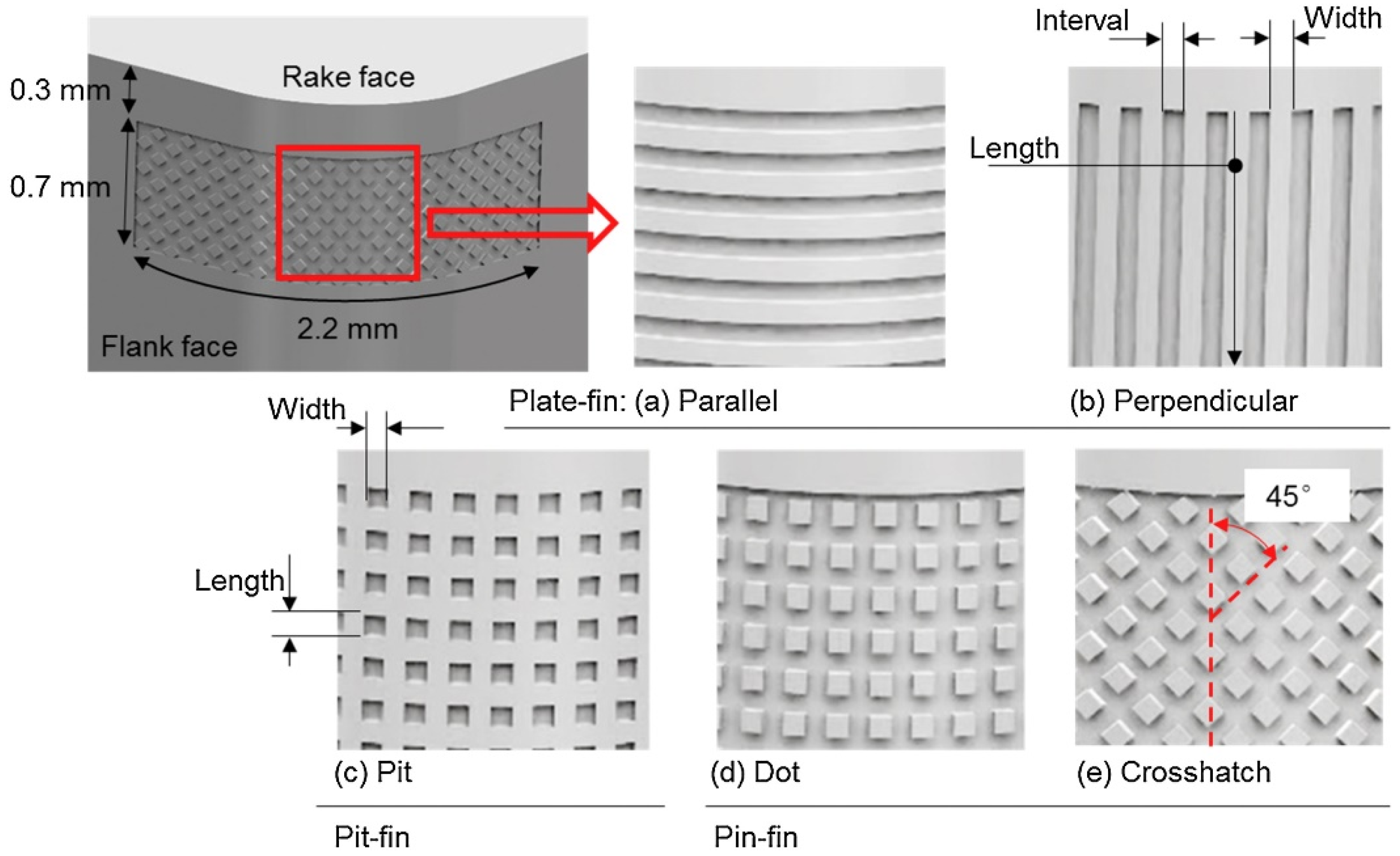
4.2. Surface Texture

There are many types of surface textures, including convex bodies, concave pits, and concave grooves, as shown in Figure 6 [130]. Concave bodies and concave pits can be made into various shapes (round, square, and hexagonal), while concave grooves can be made into straight and wavy shapes. The design of surface texture can also be linked to natural structures, especially natural structures with excellent tribological properties, which have received increasing attention in the field of lubrication and friction. These structures have inspired humans to imitate their designs and decipher the complex interactions between them to create a variety of bionic structures to minimize friction and wear. Moreover, 3D printing ceramic technology is used to manufacture bionic structural ceramics because of its high customizability and complex molding technology. Many structures in organisms have evolved into a variety of friction-reducing and wear-resistant properties through the natural selection of genes, such as the microstructure of snake abdominal scales [131], honeycomb structures [4], tree frog toe structures [132], rose petals [133], and iguana foot microstructures [134].
As a legless reptile, snakes mainly rely on their ventral feet to “slide” on the ground. The anti-adhesion, wear-resistant, and low-friction properties of snakeskin facilitate the amimals’ movement. Such tribological properties provide inspiration for the design of friction-reducing and wear-resistant structural ceramics. As shown in Figure 7a–c, snakeskin has highly ordered and deterministic diamond scales. Yu et al. [4] prepared a concave–convex Al2O3 ceramic structure of snake abdominal scale microstructure by DLP printing technology, using MoS2/h-BN two-dimensional sheet material as a lubricant. At 700 °C, the friction coefficient of the concave snakeskin-structured composite material is about 0.2, which is nearly 88.51% lower than that of unstructured Al2O3. In addition, since the concave bionic structure not only expands the contact area of the lubricant and the capture area of the abrasive particles, but also facilitates the formation of the lubricating film, the structure can achieve better lubrication improvements at different temperatures.
The honeycomb structure is a hexagonal structure. As the most stable natural form, it has been studied by the scientific community for more than a thousand years, as shown in Figure 7d–f. Since hexagons are one of the most effective ways to hold the largest number of objects in the smallest space, the honeycomb structure can help reduce friction and wear by providing a large number of micro-reservoirs to store lubricants and capture wear debris. A 3D-printed Al2O3 composite material with a concave honeycomb structure produced by Yu et al. [4] has a friction coefficient of 0.31 at room temperature, which is 46.55% lower than that of the non-structured Al2O3 sample.
Chen et al. [132] designed various bionic petal structures and tree frog toe structures for 3D-printed Al2O3 ceramics. The microstructure of natural rose petals is based on a hexagonal structure consisting of hemispherical protrusions and crater-like pits on the top of the protrusions, as shown in Figure 7h. The simulated structure of the petals has a continuous 3D micro-scale crater-like pit morphology on the top, and the closed circular pits act as crack-stopping edges. Therefore, during the friction process, cracks are easily generated in the stress concentration area on the upper contact surface. The crater-like pits can effectively cut off the crack propagation under large strains, thereby reducing the damage to the structure caused by wear [133]. They found that the hexagonal arrangement produces more lubricant and debris storage, the structure size is smaller, and its friction coefficient of 0.411 is the lowest, which is lower than the friction coefficient of blank printed Al2O3, indicating the core role of the bionic petal structure in enhancing lubrication performance.
The structure of the tree frog toe tip can be divided into three categories according to the shapes of the grooves: quadrilateral, pentagonal, and hexagonal, as shown in Figure 7i,j. According to the results, the mucus secreted by the tree frog toe surface circulates in the grooves on the toe tip, and, when the toe comes into contact with other surfaces, excess mucus can be removed from the contact surface through these grooves. Therefore, this structure is able to control and store lubricating oil extremely well. The alumina ceramics manufactured by Chen et al. [132] that imitated the hexagonal structure of the toe ends of the tree frog had the highest friction coefficient of 1.177, but the lowest wear rate.
In addition to creating surface textures during 3D printing, micro-pits can also be created during subsequent processing to improve tribological properties. Fang et al. [135] increased the space for storing lubricants on the material surface via the laser ablation of micro-pits, using a laser to create micro-pits with a diameter of 150 μm and an area density of 40% on the sample surface.
According to the above research, surface texturing affects the friction and wear properties of materials in terms of their arrangement and micro-pit distribution. The hexagonal structure can store the largest number of analogs, such as solid lubricants or wear debris, in the smallest space [136]. Compared with a dense arrangement, the hexagonal arrangement reduces the wear rate by reducing the abrasive wear caused by the accumulation of wear debris during friction. At the same time, due to the change in the pressure distribution, the hexagonal structure has a higher bearing load and exhibits excellent friction performance [137]. The micro-pit distribution of the bionic structure increases the storage capacity of the solid lubricant and reduces the friction coefficient [138]. Therefore, optimizing the tribological properties of additively manufactured ceramics can start with the adjustment of the arrangement and micro-texture units.

4.3. Lubrication

Compared with dry friction conditions, adding lubricants to the material surface can significantly reduce the friction coefficient and wear rate. Zhang et al. [29] tested the wear rate of ZrO2 samples manufactured using DLP under water lubrication conditions. Zhang et al. [35] reported that the friction coefficient of ZTA ceramic crowns manufactured by DLP in an artificial saliva environment was 0.3–0.4, which was reduced by ~0.1 compared with dry friction conditions. Branco et al. [115,125] reported that the wear rates of DIW-produced ZrO2- and ZrO2-reinforced leucite samples in an artificial saliva environment were 1.5–2.5 × 10⁻⁵ mm3·N−1·m−1 and 1–1.6 × 10⁻⁵ mm3·N−1·m−1, respectively. Ramezani et al. [11] found that the wear resistance of alumina parts prepared using solvent-based slurry stereolithography can be significantly improved using gear oil, paraffin oil, and vegetable oil. Inspired by the structure of synovial joints, Zhao et al. [139] introduced microscale Ag microspheres with a “cartilage” layer and a nanoscale Ag quantum dots/MXene “synovial fluid” into the interior and exterior of the 3D-printed SiOC “hard bone”, restoring the gradient structure of the synovial joint prototype. In dry friction sliding tests, it was found that the wear rate of the composites was 2.05 × 10⁻⁶ mm3 N−1 m−1 and the friction coefficient was only 0.11–0.13.
In the 1990s, Hirano et al. [140,141] used a model to simulate the friction behavior of two nanoscale crystal surfaces and concluded that the tribological behavior of the two crystal surfaces is closely related to the lattice. The superlubricity phenomenon is described as the static friction of the system tending to zero on the infinite non-uniform lattice surface, and there is no energy dissipation during sliding. At this time, the dynamic friction may be 0 [142,143,144]. At present, the material most likely to achieve superlubricity is a two-dimensional layered crystal. Many two-dimensional crystal materials with extremely low friction coefficients have been discovered over time, such as graphene, molybdenum disulfide, and tungsten disulfide [14,145,146,147,148]. If macroscopic superlubricity can be achieved, the tribological properties of ceramic parts in high-speed and high-temperature systems can be significantly improved.
Even if superlubricity cannot be achieved, coating the surface of a material with a two-dimensional layered material as a lubricant can significantly improve its friction and wear performance. Two-dimensional materials have a weak interlayer bonding structure and a unique, easy-to-shear protective layer, which makes them a promising candidate lubricant for reducing friction and wear in tribological systems [149]. A variety of Al2O3-based ceramics were developed based on additive manufacturing technology in order to investigate their synergistic lubrication performance with two-dimensional lamellar MoS2/BN lubricants [135,150,151]. Chen et al. [132] loaded the solid lubricant WS2 onto 3D-printed alumina ceramics using a hydrothermal method to reduce the friction of the entire tribo-system. Zhao et al. [15] introduced MoS2/GO heterostructures into the interior and surface of a well-designed SiOC structure and developed a 3D-printed SiOC-MoS2/GO structural self-lubricating composite, achieving a minimum wear depth of 1.22 × 10⁻⁷ mm.

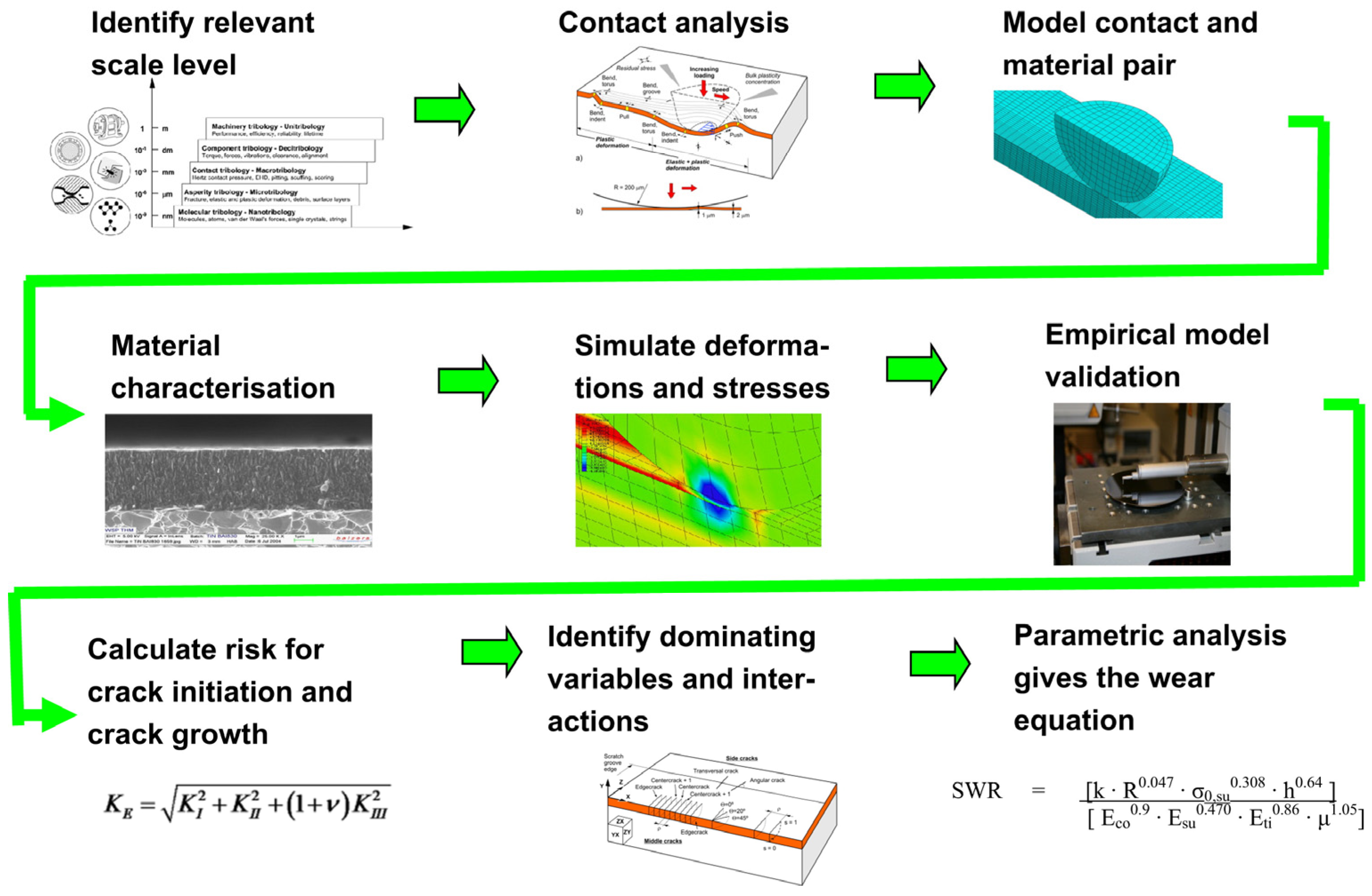
4.4. Surface Coating

Adding friction-reducing and wear-resistant coatings between or on the surface of ceramic layers is a very common process, including wear-resistant coatings that are applied to industrial devices and the glazing of ceramics. In order to study the actual improvement of materials’ wear resistance by surface coatings, a set of optimization methods have been proposed based on computational modeling and load response simulations, as shown in Figure 8. WC-Co is a commonly used wear-resistant surface coating. Enneti and Prough [43] evaluated WC-12%Co manufactured via a BJP process according to the ASTM B611 and G65 test methods, and the volume loss under the two tests was 140.48 ± 2.73 mm3 and 3.67 ± 0.66 mm3, respectively. The appropriate addition of nanoscale rare-earth-containing additives can significantly improve the microhardness and bonding strength of WC-12%Co coatings, because these rare earth-containing additives can effectively inhibit the decarburization of WC particles and refine their microstructure [152,153]. With the increase in the nanoscale rare-earth content, the hardness and friction and wear properties of the WC-10Co-4Cr coating were significantly improved from the results reported by Wang et al. [154]. When the content of the nanoscale rare-earth additive was 1.5 wt.%, the hardness of the 3D-printed coating sample increased by 42% and the coating wear was reduced by 43%.
In film production technology, a thin film is attached to the surface of the material to improve the tribological properties of the substrate. Unlike the expensive deposition process, inkjet printing can break up the ink into droplets by applying an external electric field under normal temperature and pressure conditions and can print a dense and uniform film in the desired area [156]. Bao et al. [157] prepared a TaS2 soft film on the surface of Al2O3/TiC ceramics via electro-hydrodynamic atomization. The synergistic effects of the TaS2 film and bionic texture showed excellent benefits in reducing the wear rate and improving the wear life of the substrate.
When manufacturing artificial teeth, the material is glazed to improve the wear resistance, as well as ensuring the appropriate aesthetics and antibacterial properties of artificial teeth in the oral environment. Branco et al. [115] compared the tribological behavior of glazed zirconia with that of unglazed zirconia and found that glazing can greatly reduce tip wear and wear depth. At the same time, adding an SDF + KI coating can inhibit the proliferation of Staphylococcus aureus, indicating the potential benefits of the coating in preventing the pathogenic bacterial complications associated with artificial crown implantation.

5. Typical Tribological Applications of Ceramic Additive Manufacturing Technology

At present, the interacting surfaces in relative motion in some fields require ceramic components with good tribological properties to achieve specific applications. There are specific demands in tribology, such as in aviation, aerospace, energy, metallurgy, electronics industries, and biomedical implants. The relevant parts include impellers, bearings, bushings, screws and nuts, blast nozzles, cutting tools, dental crowns, implants, hip prostheses, bone tissue engineering parts, pumps, dies, valves, seals, and other rotatory or sliding tribo-components. Ceramic materials are used as raw materials for manufacturing these parts due to their high hardness and wear resistance. However, traditional ceramic-forming methods, such as dry pressing, isostatic pressing, and injection molding, have many limitations. For example, they cannot be used for parts with complex shapes (with multi-layered walls, inner holes, complicated flow passageways, sharp corners, etc.) or parts with high precision and shape/property integration requirements. The advantages of additive manufacturing over traditional manufacturing technology have allowed ceramic parts based on 3D printing to gradually enter multiple fields.

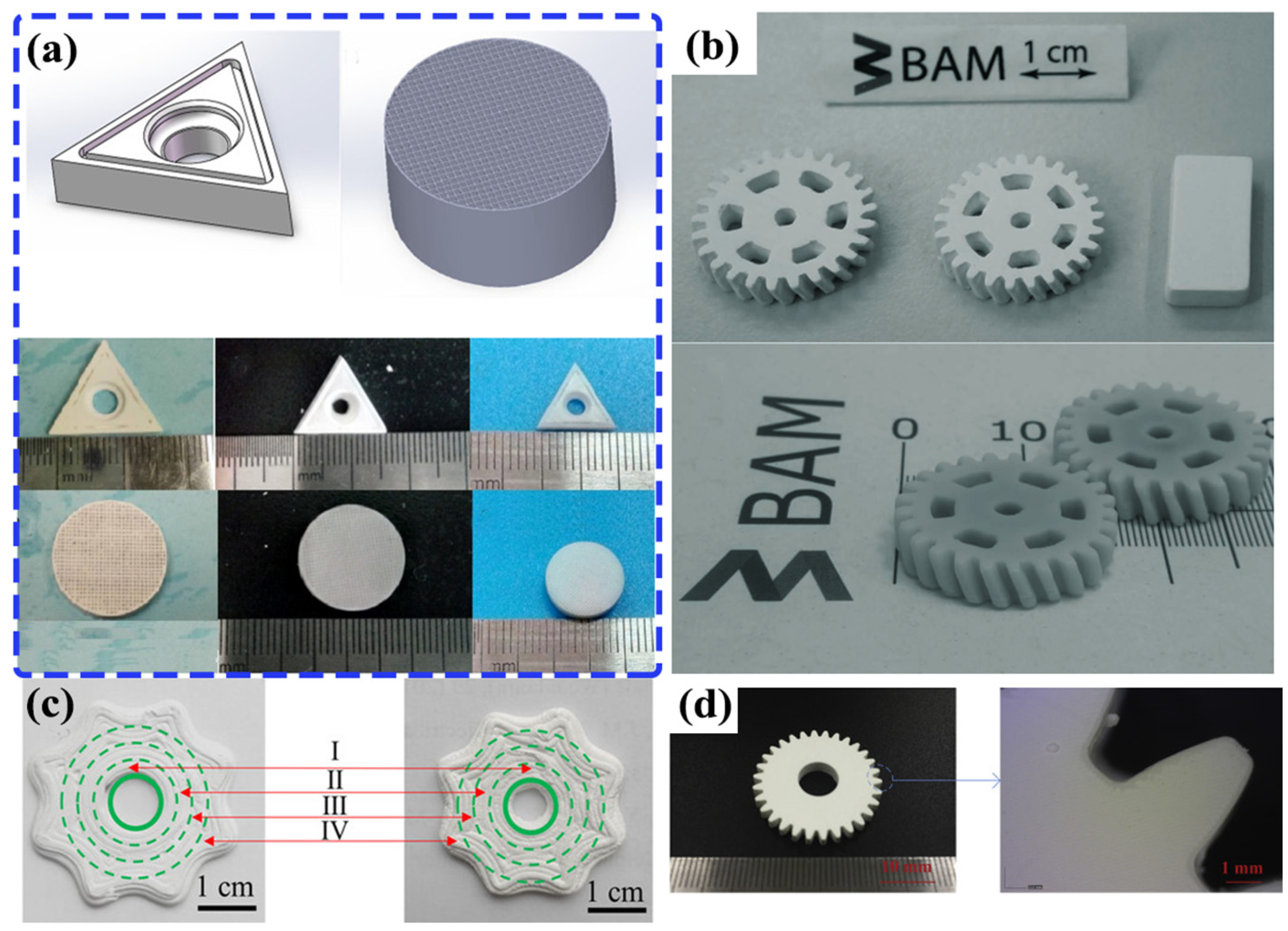
5.1. Industrial Devices

Cutting tools are needed to produce a variety of materials in industrial production. Cutting tool materials must have strong hardness, wear resistance, and compressive strength. Currently, they are mostly made by sintering ceramic or cermet powders containing tungsten carbide, titanium carbide, titanium carbonitride, or other types of hard phases. SLM-based cermets have low wear rates at high temperatures and are increasingly used to achieve this goal. Davydova et al. [40] verified the feasibility of using SLM to manufacture B4C/Co cermet tools.
Stereolithographic 3D printing technology has higher precision and can meet the needs of complex structure design in tools. He et al. [31] manufactured a complex triangular zirconia tool with a tool extraction groove and a honeycomb ceramic component based on DLP technology, as shown in Figure 9a. The setting of chip breaker grooves can improve the chip removal rate and reduce the tool tip temperature and cutting force [123,124,158]. Liu et al. [123] conducted a study of zirconia-toughened alumina (ZTA) ceramic tools equipped with chip breakers produced via vat photopolymerization-based 3D printing, and found that ceramic cutting tools are mainly subjected to adhesive wear and abrasive wear during cutting, with continuous diffusion wear in the non-adhesive wear zone. Wu et al. [124] fabricated an Al2O3 ceramic cutting tools with chip breaker grooves based on SLA-3D printing and found that the cutting speed had the greatest influence on the cutting performance, while the cutting depth had the least influence. The wear mechanisms associated with Al2O3 cutting tools were abrasive and adhesive wear.
Gears are transmission components, and wear between gears is a major problem. The degree of meshing between gears affects the degree of wear between gears. Gears manufactured using additive manufacturing have higher precision and avoid the wear caused by meshing problems. Studies have been conducted on using 3D printing to manufacture high-precision and high-strength ceramic gears, including Al2O3 and its composite materials, as shown in Figure 9 [12,24,42].

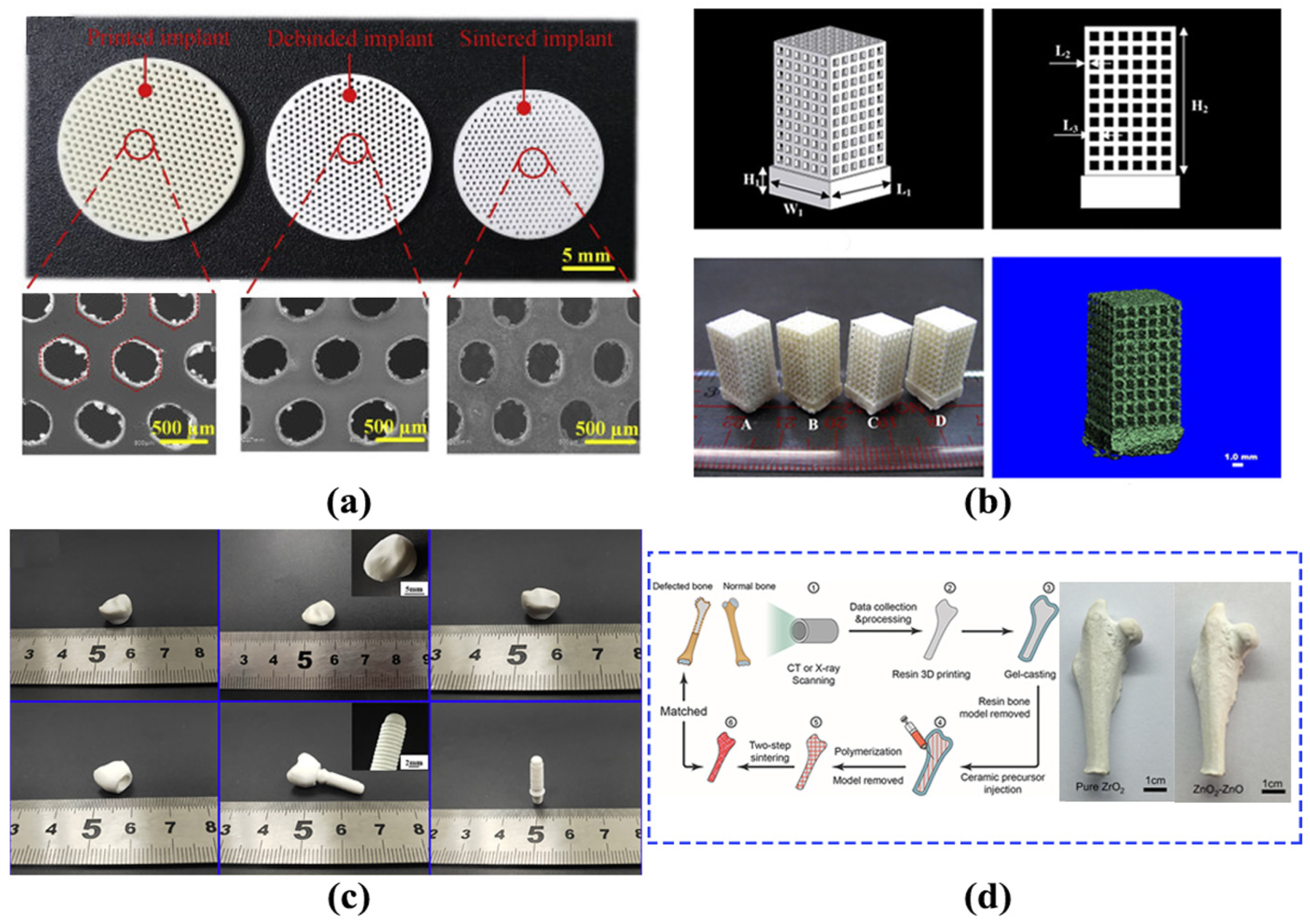
5.2. Biomedical Applications

Human bones and teeth wear out during use due to collision, friction, and other reasons. When a person must replace artificial bones or artificial teeth for some reason, it is important to consider using materials with excellent tribological properties; among these materials, ceramic materials (such as zirconium oxide, alumina, and hydroxyapatite [159,160]) have better biocompatibility and wear resistance than metal materials. The manufacture of ideal ceramic biomedical parts is not only related to the composition of the material but is also affected by its macrostructure and microstructure. Therefore, it is urgently necessary to develop complex geometric molding techniques. At present, additive manufacturing technology provides a new method for this process.
Hydroxyapatite has sufficient osteoconductive properties and good bioaffinity, which is sufficient to form strong chemical bonds and mechanical interlocking with bones; it is conducive to being replaced or integrated into host bones. Chen et al. [25] mixed hydroxyapatite powder into a photosensitive resin based on SLA technology to form a complex-shaped scaffold. They finally prepared a HAP sample with good biosafety that can be implanted in the rabbit parietal bone (Figure 10a). Duan et al. [41] used SLS technology to manufacture bionic bone scaffolds based on calcium phosphate (Ca-P)/poly (hydroxybutyrate–co-hydroxyvalerate) (PHBV) and carbonated hydroxyapatite (CHAP)/poly(L-lactic acid) (PLLA) nanocomposite microspheres, which are superior to pure polymer scaffolds in terms of both their mechanical properties and wear resistance (Figure 10b).
Zirconia ceramics and zirconia-based composite ceramics are widely used in clinical practice as tooth restoration materials due to their excellent chemical stability, mechanical properties, wear resistance, and corrosion resistance [162]. Zhang et al. [29] prepared high-density zirconia ceramic crowns based on DLP technology, which is a sintered type of 3Y-TZP ceramic crown. The Vickers hardness and wear resistance of zirconia ceramic crowns used for tooth restoration reached 12.62 GPa and 1.5 mg/min, respectively. Branco et al. [115] manufactured ceramic samples using leucite slurry reinforced with zirconia nanoparticles based on 3D printing technology, which showed negligible wear in simulated oral chewing tests and minimal wear on antagonistic tooth cusps. Compared with glazed ZrO2 (a common choice in dental practice), the obtained material showed excellent optical properties and tribomechanical behavior. Zhang et al. [35] verified that the surface of ZrO2(3Y)/Al2O3 dental implants manufactured by DLP technology has appropriate roughness and good wettability in the oral environment (Figure 10c). The wear loss of the ZTA sample sintered at 1650 °C was the lowest, only 1.6 mg, which is lower than that of human enamel. Zhu et al. [161] manufactured ZrO2 and ZrO2-ZrO hip prostheses with long-term wear resistance based on ceramic 3D printing technology, as shown in Figure 10d. Additionally, 3D printing can be used to manufacture both dental ceramics and processing tools with neatly arranged diamond particles for grinding dental ceramics. Grinding tests on machined ZrO2 crowns confirmed that no abrasive falling off occurs on the surface of the 3D-printed diamond tool [163]. Li et al. [164] designed an SLA-3D-printed ZrO2 interference screw for the reconstruction of the human anterior cruciate ligament with a forming accuracy of 80.0 ± 21.1 μm and good mechanical properties.

6. Summary and Prospects

This article focuses on the additive manufacturing of ceramic materials with advanced structures. It first explains the principles and technologies in the field of additive manufacturing, as well as the production methods and processing factors of the corresponding ceramics. Then, ceramic materials used for additive manufacturing are classified according to their composition, and the applicability and application fields of each ceramic system in relation to tribology are summarized. The effects of conventional dense ceramics, surface textures, lubrication, and surface coatings on different tribological and mechanical properties are discussed. The tribological and mechanical properties of ceramic materials based on additive manufacturing are comparable to or can further improve on those of samples manufactured using conventional processes. Finally, the current applications and possible developments of ceramic materials based on additive manufacturing in industrial production and biomedical implants are introduced. In order to further improve the tribological properties of materials, the following challenges are addressed in using ceramic materials based on additive manufacturing:
  • Additive manufacturing technology is not yet mature in the field of ceramics, and the manufacturing process is needed to be further improved, such as by improving the high-temperature rheological properties of ceramic powders and adhesive composites in extrusion-based 3D printing, the influence of ceramic powders on the absorbance of slurry in photocuring 3D printing, surface irregularities in powder-melting 3D printing, and the rheological properties of printing inks in powder-bonding 3D printing.
  • Additively manufactured structural ceramic systems used in tribological applications include oxide ceramics, non-oxide ceramics, bioceramics, MAX phases, and composite ceramics, according to the property requirements. MAX-phase ceramics can reduce the friction coefficient and wear, and they represent a very promising material with excellent tribological properties. Combining them with near-net-shape forming technology is a future development direction in additive manufactured ceramics.
  • The combination of different additive manufacturing technologies with multi-material systems can integrate their respective advantages for various structural/functional integrated applications. By combining various mechanisms and technologies, the friction and wear performance of ceramics can be maximized by designing novel surface textures, surface lubrication, and surface coatings, which represents a new research direction.
  • As an extension of 3D printing technology, 4D printing technology can change the shapes or structures printed using 3D technology under external stimulation, directly embed the deformation design of materials and structures into the material, and simplify the creation process from design concept to physical object. This will allow for a novel design, manufacturing and assembly of integrated ceramic parts.
  • The realization of the macroscopic superlubricity phenomenon and bionic structure design are two hot research directions for the future development of friction-reducing and wear-resistant ceramic components. Both the two-dimensional layered structure and the structure of synovial joints have excellent tribological properties. Additive manufacturing for the precision manufacturing of complex structures can be used as a good solution to this problem. However, the high costs and difficulty in the industrialization of these technologies have become major limiting factors.

Author Contributions

Conceptualization, W.-J.M. and J.-H.O.; validation, W.-J.M., J.-H.O. and S.-Q.W.; investigation, W.-J.M., Z.-H.W., Y.-Z.Z. and F.-B.W.; resources, W.-J.M., Z.-H.W., Y.-Z.Z. and F.-B.W.; data curation, W.-J.M., Z.-H.W. and F.-B.W.; writing—original draft preparation, W.-J.M.; writing—review and editing, J.-H.O. and S.-Q.W.; visualization, W.-J.M. and Y.-M.W.; supervision, J.-H.O. and Y.-C.Z.; funding acquisition, J.-H.O. All authors have read and agreed to the published version of the manuscript.

Funding

This work was financially supported by the National Key R & D Program of China under grant No. 2023YFB4606104.

Data Availability Statement

Not applicable.

Conflicts of Interest

The authors declare no conflicts of interest.

Abbreviations

AMAdditive manufacturing
FDMFused deposition modelling
DIWDirect ink writing
SLAStereolithography
DLPDigital light processing
TPPTwo-photon polymerization
SLMSelective laser melting
SLSSelective laser sintering
BJPBinder jet 3D Printing
CSLCeramic stereolithography
LSDLayered slurry deposition
TEOSTetraethyl orthosilicate
PRCPyrolytic carbon
LSILiquid silicon infiltration
HAPHydroxyapatite
CHAPCarbonated hydroxyapatite
FApFluorapatite
μFriction coefficient

References

  1. Holmberg, K.; Erdemir, A. Influence of Tribology on Global Energy Consumption, Costs and Emissions. Friction 2017, 5, 263–284. [Google Scholar] [CrossRef]
  2. Ouyang, J.H.; Li, Y.F.; Wang, Y.M.; Zhou, Y.; Murakami, T.; Sasaki, S. Microstructure and Tribological Properties of ZrO2(Y2O3) Matrix Composites Doped with Different Solid Lubricants from Room Temperature to 800 °C. Wear 2009, 267, 1353–1360. [Google Scholar] [CrossRef]
  3. Ouyang, J.-H.; Li, Y.-F.; Zhang, Y.-Z.; Wang, Y.-M.; Wang, Y.-J. High-Temperature Solid Lubricants and Self-Lubricating Composites: A Critical Review. Lubricants 2022, 10, 177. [Google Scholar] [CrossRef]
  4. Zhao, Y.; Mei, H.; Chang, P.; Yang, Y.; Cheng, L.; Zhang, L. High-Strength Printed Ceramic Structures for Higher Temperature Lubrication. Compos. Part B Eng. 2021, 221, 109013. [Google Scholar] [CrossRef]
  5. Ren, J.; Zhang, Y.; Zhao, D.; Chen, Y.; Guan, S.; Liu, Y.; Liu, L.; Peng, S.; Kong, F.; Poplawsky, J.D.; et al. Strong yet Ductile Nanolamellar High-Entropy Alloys by Additive Manufacturing. Nature 2022, 608, 62–68. [Google Scholar] [CrossRef]
  6. Bandyopadhyay, A.; Heer, B. Additive Manufacturing of Multi-Material Structures. Mater. Sci. Eng. R Rep. 2018, 129, 1–16. [Google Scholar] [CrossRef]
  7. Li, Y.; Sheng, P.; Lin, L.; Wang, L.; Lu, D.; Lin, K.; Wu, H.; Wu, S. Vat Photopolymerization versus Conventional Colloidal Processing Methods in Structural Ceramics: Progress, Challenges, and Future Perspectives. Addit. Manuf. Front. 2024, 3, 200110. [Google Scholar] [CrossRef]
  8. Yao, X.; Liu, S.; Ji, Z.; Guo, R.; Sun, C.; Guo, Y.; Wang, X.; Wang, Q. 3D Printing of PTFE-Filled Polyimide for Programmable Lubricating in the Region Where Lubrication Is Needed. Tribol. Int. 2022, 167, 107405. [Google Scholar] [CrossRef]
  9. Guo, Y.; Xu, J.; Yan, C.; Chen, Y.; Zhang, X.; Jia, X.; Liu, Y.; Wang, X.; Zhou, F. Direct Ink Writing of High Performance Architectured Polyimides with Low Dimensional Shrinkage. Adv. Eng. Mater. 2019, 21, 1801314. [Google Scholar] [CrossRef]
  10. Abdelkader, M.; Petrik, S.; Nestler, D.; Fijalkowski, M. Ceramics 3D Printing: A Comprehensive Overview and Applications, with Brief Insights into Industry and Market. Ceramics 2024, 7, 68–85. [Google Scholar] [CrossRef]
  11. Ramezani, M.; Dommati, H.; Wang, J.-C.; Pasang, T.; Lee, C. Tribological Characterization of Alumina Ceramic Manufactured by Solvent-Based Slurry Stereolithography. J. Mater. Eng. Perform. 2023, 32, 8325–8336. [Google Scholar] [CrossRef]
  12. Fan, J.; Guan, R.; Ou, K.; Fu, Q.; Liu, Q.; Li, D.; Zheng, H.; Sun, Y. Direct Ink Writing 3D Printing of Graphene/Al2O3 Composite Ceramics with Gradient Mechanics. Adv. Eng. Mater. 2023, 25, 2201414. [Google Scholar] [CrossRef]
  13. Lei, B.; Xiong, H.; Chen, K. Comparison of Wear and Marginal Fitness of 3D-Printed Deciduous Molar Crowns: An in Vitro Study. Dent. Mater. J. 2024, 43, 227–234. [Google Scholar] [CrossRef]
  14. Zhao, Y.; Mei, H.; Chang, P.; Yang, Y.; Huang, W.; Liu, Y.; Cheng, L.; Zhang, L. 3D-Printed Topological MoS2 /MoSe2 Heterostructures for Macroscale Superlubricity. ACS Appl. Mater. Interfaces 2021, 13, 34984–34995. [Google Scholar] [CrossRef]
  15. Zhao, Y.; Yang, L.; Liu, Y.; Li, Y.; Xie, G.; Chang, P.; Mei, H.; Cheng, L.; Zhang, L. Internal and External MoS2/GO Heterostructure Enhanced Multi-Point Contact Egg-Box Inspired SiOC for Macroscopic Ultra-Low Friction. Carbon 2024, 221, 118908. [Google Scholar] [CrossRef]
  16. Yuan, W.; Yao, Y.; Keer, L.; Jiao, Y.; Yu, J.; Li, Q.; Feng, X.-Q. 3D-Printed Biomimetic Surface Structures with Abnormal Friction Properties. Extrem. Mech. Lett. 2019, 26, 46–52. [Google Scholar] [CrossRef]
  17. ISO/ASTM 52900:2021(En), Additive Manufacturing—General Principles—Fundamentals and Vocabulary. Available online: https://www.iso.org/obp/ui/#iso:std:iso-astm:52900:ed-2:v1:en (accessed on 9 December 2024).
  18. Sun, H.; Zou, B.; Wang, X.; Chen, W.; Zhang, G.; Quan, T.; Huang, C. Advancements in Multi-Material Additive Manufacturing of Advanced Ceramics: A Review of Strategies, Techniques and Equipment. Mater. Chem. Phys. 2024, 319, 129337. [Google Scholar] [CrossRef]
  19. Cheype, M.; Pateloup, V.; Bernard, S. Straightforward Design Strategy toward 3D Near-Net-Shape Stoichiometric SiC Parts. Adv. Mater. 2024, 36, 2307554. [Google Scholar] [CrossRef]
  20. Kong, F.; Chen, X.; Li, Y.; Tian, L.; Zheng, F.; Wang, E.; Zhao, G. A Novel Approach to Prepare High Density SiC Ceramics by Powder Extrusion Printing (PEP) Combined with One-Step Sintering Method. J. Eur. Ceram. Soc. 2024, 44, 626–634. [Google Scholar] [CrossRef]
  21. Liu, Y.; Liu, Y.; Zhang, W.; Peng, Y.; Zhang, W.; Zhu, X.; Xiong, X.; Wu, M.; Liu, B. Integrating Shape and Performance Control in Polycrystalline Cubic Boron Nitride Fabricated Using Powder Extrusion Printing. Int. J. Refract. Met. Hard Mater. 2023, 115, 106304. [Google Scholar] [CrossRef]
  22. Yu, T.; Zhang, Z.; Liu, Q.; Kuliiev, R.; Orlovskaya, N.; Wu, D. Extrusion-Based Additive Manufacturing of Yttria-Partially-Stabilized Zirconia Ceramics. Ceram. Int. 2020, 46, 5020–5027. [Google Scholar] [CrossRef]
  23. Mamatha, S.; Biswas, P.; Ramavath, P.; Das, D.; Johnson, R. 3D Printing of Complex Shaped Alumina Parts. Ceram. Int. 2018, 44, 19278–19281. [Google Scholar] [CrossRef]
  24. Liu, X.; Zou, B.; Xing, H.; Huang, C. The Preparation of ZrO2-Al2O3 Composite Ceramic by SLA-3D Printing and Sintering Processing. Ceram. Int. 2020, 46, 937–944. [Google Scholar] [CrossRef]
  25. Chen, Q.; Zou, B.; Lai, Q.; Wang, Y.; Xue, R.; Xing, H.; Fu, X.; Huang, C.; Yao, P. A Study on Biosafety of HAP Ceramic Prepared by SLA-3D Printing Technology Directly. J. Mech. Behav. Biomed. Mater. 2019, 98, 327–335. [Google Scholar] [CrossRef]
  26. Ding, G.; He, R.; Zhang, K.; Zhou, N.; Xu, H. Stereolithography 3D Printing of SiC Ceramic with Potential for Lightweight Optical Mirror. Ceram. Int. 2020, 46, 18785–18790. [Google Scholar] [CrossRef]
  27. Huang, Z.; Liu, L.Y.; Yuan, J.; Guo, H.; Wang, H.; Ye, P.; Du, Z.; Zhao, Y.; Zhang, H.; Gan, C.L. Stereolithography 3D Printing of Si3N4 Cellular Ceramics with Ultrahigh Strength by Using Highly Viscous Paste. Ceram. Int. 2023, 49, 6984–6995. [Google Scholar] [CrossRef]
  28. Zhang, G.; Jiang, J.; Wang, H.; Qian, L.; Lan, H. Continuous DLP-Based Ceramic 3D Printing Using a Composite Oxygen-Rich Film. J. Manuf. Process. 2021, 64, 341–348. [Google Scholar] [CrossRef]
  29. Zhang, F.; Zuo, Y.; Zhang, K.; Gao, H.; Zhang, S.; Chen, H.; Liu, G.; Jin, X.; Yang, J. Fabrication of Zirconia Ceramic Dental Crowns by Digital Light Processing: Effects of the Process on Physical Properties and Microstructure. 3d Print. Addit. Manuf. 2024, 11, e1257–e1270. [Google Scholar] [CrossRef]
  30. Mohammadi, M.; Coppola, B.; Montanaro, L.; Palmero, P. Digital Light Processing of High-Strength Hydroxyapatite Ceramics: Role of Particle Size and Printing Parameters on Microstructural Defects and Mechanical Properties. J. Eur. Ceram. Soc. 2023, 43, 2761–2772. [Google Scholar] [CrossRef]
  31. He, R.; Liu, W.; Wu, Z.; An, D.; Huang, M.; Wu, H.; Jiang, Q.; Ji, X.; Wu, S.; Xie, Z. Fabrication of Complex-Shaped Zirconia Ceramic Parts via a DLP- Stereolithography-Based 3D Printing Method. Ceram. Int. 2018, 44, 3412–3416. [Google Scholar] [CrossRef]
  32. Tang, J.; Guo, X.; Chang, H.; Hu, K.; Shen, Z.; Wang, W.; Liu, M.; Wei, Y.; Huang, Z.; Yang, Y. The Preparation of SiC Ceramic Photosensitive Slurry for Rapid Stereolithography. J. Eur. Ceram. Soc. 2021, 41, 7516–7524. [Google Scholar] [CrossRef]
  33. Qu, P.; Liang, G.; Hamza, M.; Mo, Y.; Jiang, L.; Luo, X.; Liu, Z.; Liu, C.; Lou, Y.; Chen, Z. 3D Printing of High-Purity Complex SiC Structures Based on Stereolithography. Ceram. Int. 2024, 50, 23763–23774. [Google Scholar] [CrossRef]
  34. Tang, J.; Chang, H.; Guo, X.; Liu, M.; Wei, Y.; Huang, Z.; Yang, Y. Preparation of Photosensitive SiO2/SiC Ceramic Slurry with High Solid Content for Stereolithography. Ceram. Int. 2022, 48, 30332–30337. [Google Scholar] [CrossRef]
  35. Zhang, L.; Liu, H.; Yao, H.; Zeng, Y.; Chen, J. Preparation, Microstructure, and Properties of ZrO2(3Y)/Al2O3 Bioceramics for 3D Printing of All-Ceramic Dental Implants by Vat Photopolymerization. Chin. J. Mech. Eng. Addit. Manuf. Front. 2022, 1, 100023. [Google Scholar] [CrossRef]
  36. Zou, R.; Bi, L.; Huang, Y.; Wang, Y.; Wang, Y.; Li, L.; Liu, J.; Feng, L.; Jiang, X.; Deng, B. A Biocompatible Silicon Nitride Dental Implant Material Prepared by Digital Light Processing Technology. J. Mech. Behav. Biomed. Mater. 2023, 141, 105756. [Google Scholar] [CrossRef] [PubMed]
  37. Prediger, R.; Sriyotha, N.; Schell, K.G.; Kluck, S.; Hambitzer, L.; Kotz-Helmer, F. Two-Photon Polymerization of Nanocomposites for Additive Manufacturing of Transparent Magnesium Aluminate Spinel Ceramics. Adv. Sci. 2024, 11, 2307175. [Google Scholar] [CrossRef]
  38. Chai, N.; Yue, Y.; Chen, X.; Zeng, Z.; Li, S.; Wang, X. Isotropic Sintering Shrinkage of 3D Glass-Ceramic Nanolattices: Backbone Preforming and Mechanical Enhancement. Int. J. Extrem. Manuf. 2024, 6, 025003. [Google Scholar] [CrossRef]
  39. Shishkovsky, I.; Yadroitsev, I.; Bertrand, P.; Smurov, I. Alumina–Zirconium Ceramics Synthesis by Selective Laser Sintering/Melting. Appl. Surf. Sci. 2007, 254, 966–970. [Google Scholar] [CrossRef]
  40. Davydova, A.; Domashenkov, A.; Sova, A.; Movtchan, I.; Bertrand, P.; Desplanques, B.; Peillon, N.; Saunier, S.; Desrayaud, C.; Bucher, S.; et al. Selective Laser Melting of Boron Carbide Particles Coated by a Cobalt-Based Metal Layer. J. Mater. Process. Technol. 2016, 229, 361–366. [Google Scholar] [CrossRef]
  41. Duan, B.; Wang, M.; Zhou, W.Y.; Cheung, W.L.; Li, Z.Y.; Lu, W.W. Three-Dimensional Nanocomposite Scaffolds Fabricated via Selective Laser Sintering for Bone Tissue Engineering. Acta Biomater. 2010, 6, 4495–4505. [Google Scholar] [CrossRef]
  42. Zocca, A.; Lima, P.; Günster, J. LSD-Based 3D Printing of Alumina Ceramics. J. Ceram. Sci. Technol. 2017, 08, 141–148. [Google Scholar] [CrossRef]
  43. Enneti, R.K.; Prough, K.C. Wear Properties of Sintered WC-12%Co Processed via Binder Jet 3D Printing (BJ3DP). Int. J. Refract. Met. Hard Mater. 2019, 78, 228–232. [Google Scholar] [CrossRef]
  44. Huang, S.; Wu, H.; Jiang, C.; Fu, X.; Liu, Y.; Zhang, J.; He, L.; Yang, P.; Deng, X.; Wu, S. Preparation of High-Strength ZrO2 Ceramics by Binder Jetting Additive Manufacturing and Liquid Glass Infiltration. Ceram. Int. 2024, 50, 44175–44185. [Google Scholar] [CrossRef]
  45. Lu, X.; Liu, G.; Lu, J. Development of Ceramic 3D/4D Printing in China. Addit. Manuf. Front. 2024, 3, 200158. [Google Scholar] [CrossRef]
  46. Li, L.; Lin, Q.; Tang, M.; Duncan, A.J.E.; Ke, C. Advanced Polymer Designs for Direct-Ink-Write 3D Printing. Chem. A Eur. J 2019, 25, 10768–10781. [Google Scholar] [CrossRef]
  47. Wang, F.; Luo, F.; Huang, Y.; Cao, X.; Yuan, C. 4D Printing Via Multispeed Fused Deposition Modeling. Adv. Mater. Technol. 2023, 8, 202201383. [Google Scholar] [CrossRef]
  48. Feilden, E.; Blanca, E.G.-T.; Giuliani, F.; Saiz, E.; Vandeperre, L. Robocasting of Structural Ceramic Parts with Hydrogel Inks. J. Eur. Ceram. Soc. 2016, 36, 2525–2533. [Google Scholar] [CrossRef]
  49. Wen, J.; Xie, Z.; Cao, W.; Yang, X. Effects of Different Backbone Binders on the Characteristics of Zirconia Parts Using Wax-Based Binder System via Ceramic Injection Molding. J. Adv. Ceram. 2016, 5, 321–328. [Google Scholar] [CrossRef]
  50. Chen, X.; Li, Y.; Zhao, G. Preparation and Characterization of 3D Printed ZrO2 Ceramic Parts Fabricated by Powder Extrusion Printing. Ceram. Int. 2023, 49, 2721–2729. [Google Scholar] [CrossRef]
  51. Yang, W.-W.; Yang, K.-Y.; Wang, M.-C.; Hon, M.-H. Solvent Debinding Mechanism for Alumina Injection Molded Compacts with Water-Soluble Binders. Ceram. Int. 2003, 29, 745–756. [Google Scholar] [CrossRef]
  52. Lim, I.Y.; Ting, C.H.; Ng, C.K.; Tey, J.Y.; Yeo, W.H.; Ramesh, S.; Lee, K.Y.S.; Chuah, Y.D.; Teng, W.D. 3D Printing of High Solid Loading Zirconia Feedstock via Screw-Based Material Extrusion. Ceram. Int. 2023, 49, 24852–24860. [Google Scholar] [CrossRef]
  53. Yi, Z.; Shen, T.; Xiong, H.; Kang, X.; Zhang, L.; Zhou, K. Strong and Densified 3D Metal-Ceramic Composite with Strengthened Layer Structure by Material Extrusion Additive Manufacturing. Addit. Manuf. 2024, 84, 104136. [Google Scholar] [CrossRef]
  54. Sarraf, F.; Hadian, A.; Churakov, S.V.; Clemens, F. EVA-PVA Binder System for Polymer Derived Mullite Made by Material Extrusion Based Additive Manufacturing. J. Eur. Ceram. Soc. 2023, 43, 530–541. [Google Scholar] [CrossRef]
  55. Diptanshu; Miao, G.; Ma, C. Vat Photopolymerization 3D Printing of Ceramics: Effects of Fine Powder. Manuf. Lett. 2019, 21, 20–23. [Google Scholar] [CrossRef]
  56. Li, Q.; Pan, Z.; Liang, J.; Zhang, Z.; Li, J.; Zhou, Y.; Sun, X. Ceramic Composites Toughened by Vat Photopolymerization 3D Printing Technology. J. Mater. Sci. Technol. 2023, 146, 42–48. [Google Scholar] [CrossRef]
  57. Ding, G.; He, R.; Zhang, K.; Xie, C.; Wang, M.; Yang, Y.; Fang, D. Stereolithography-based Additive Manufacturing of Gray-colored SiC Ceramic Green Body. J. Am. Ceram. Soc. 2019, 102, 7198–7209. [Google Scholar] [CrossRef]
  58. Hull, C.W. Apparatus for Production of Three-Dmensonal Objects by Stereothography. United. States Patent 4,575,330, 11 March 1986. [Google Scholar]
  59. Subedi, S.; Liu, S.; Wang, W.; Naser Shovon, S.M.A.; Chen, X.; Ware, H.O.T. Multi-Material Vat Photopolymerization 3D Printing: A Review of Mechanisms and Applications. npj Adv. Manuf. 2024, 1, 9. [Google Scholar] [CrossRef]
  60. Jian, B.; Li, H.; He, X.; Wang, R.; Yang, H.Y.; Ge, Q. Two-Photon Polymerization-Based 4D Printing and Its Applications. Int. J. Extrem. Manuf. 2024, 6, 012001. [Google Scholar] [CrossRef]
  61. Bin, F.-C.; Zheng, M.-L. Perspective on Water-Soluble Two-Photon Initiator for Two-Photon Polymerization. ACS Appl. Mater. Interfaces 2024, 16, 51807–51815. [Google Scholar] [CrossRef]
  62. Geng, Q.; Wang, D.; Chen, P.; Chen, S.-C. Ultrafast Multi-Focus 3-D Nano-Fabrication Based on Two-Photon Polymerization. Nat. Commun. 2019, 10, 2179. [Google Scholar] [CrossRef]
  63. Sugioka, K.; Cheng, Y. Ultrafast Lasers—Reliable Tools for Advanced Materials Processing. Light Sci. Appl. 2014, 3, e149. [Google Scholar] [CrossRef]
  64. Bobrin, V.A.; Yao, Y.; Shi, X.; Xiu, Y.; Zhang, J.; Corrigan, N.; Boyer, C. Nano- to Macro-Scale Control of 3D Printed Materials via Polymerization Induced Microphase Separation. Nat. Commun. 2022, 13, 3577. [Google Scholar] [CrossRef] [PubMed]
  65. Chen, Z.; Li, Z.; Li, J.; Liu, C.; Lao, C.; Fu, Y.; Liu, C.; Li, Y.; Wang, P.; He, Y. 3D Printing of Ceramics: A Review. J. Eur. Ceram. Soc. 2019, 39, 661–687. [Google Scholar] [CrossRef]
  66. Zakeri, S.; Vippola, M.; Levänen, E. A Comprehensive Review of the Photopolymerization of Ceramic Resins Used in Stereolithography. Addit. Manuf. 2020, 35, 101177. [Google Scholar] [CrossRef]
  67. Liu, J.; Wang, Q.; Li, Y.; Zhu, T.; Liang, X.; Xu, Y. Wettability and Infiltration of Si Melt on SiO2-Si3N4 Composite Ceramic. J. Eur. Ceram. Soc. 2021, 41, 389–399. [Google Scholar] [CrossRef]
  68. Lee, M.; Rizzo, R.; Surman, F.; Zenobi-Wong, M. Guiding Lights: Tissue Bioprinting Using Photoactivated Materials. Chem. Rev. 2020, 120, 10950–11027. [Google Scholar] [CrossRef]
  69. Lemma, E.D.; Spagnolo, B.; Vittorio, M.D.; Pisanello, F. Studying Cell Mechanobiology in 3D: The Two-Photon Lithography Approach. Trends Biotechnol. 2019, 37, 358–372. [Google Scholar] [CrossRef]
  70. Zimbeck, W.; Rice, R. Stereolithography of Ceramics and Metals. In Proceedings of the IS&T’s 50th Annual Conference, Cambridge, MA, USA, 18–23 May 1997; pp. 649–655. [Google Scholar]
  71. Melchels, F.P.W. Preparation of Advanced Porous Structures by Stereolithography for Application in Tissue Engineering. Ph.D. Thesis, University of Twente, Enschede, The Netherlands, 2010. [Google Scholar]
  72. Román-Manso, B.; Weeks, R.D.; Truby, R.L.; Lewis, J.A. Embedded 3D Printing of Architected Ceramics via Microwave-Activated Polymerization. Adv. Mater. 2023, 35, 2209270. [Google Scholar] [CrossRef]
  73. Liu, S.; Mo, L.; Bi, G.; Chen, S.; Yan, D.; Yang, J.; Jia, Y.-G.; Ren, L. DLP 3D Printing Porous β-Tricalcium Phosphate Scaffold by the Use of Acrylate/Ceramic Composite Slurry. Ceram. Int. 2021, 47, 21108–21116. [Google Scholar] [CrossRef]
  74. Wu, E.-S.; Strickler, J.H.; Harrell, W.R.; Webb, W.W. Two-Photon Lithography for Microelectronic Application; Cuthbert, J.D., Ed.; SPIE: San Jose, CA, USA, 1992; p. 776. [Google Scholar]
  75. Maruo, S.; Nakamura, O.; Kawata, S. Three-Dimensional Microfabrication with Two-Photon-Absorbed Photopolymerization. Opt. Lett. 1997, 22, 132–134. [Google Scholar] [CrossRef]
  76. Aramian, A.; Razavi, N.; Berto, F.; Sadeghian, Z. A Review of Additive Manufacturing of Cermets. Addit. Manuf. 2020, 33, 101130. [Google Scholar]
  77. Chen, J.; Huang, M.; Fang, Z.Z.; Koopman, M.; Liu, W.; Deng, X.; Zhao, Z.; Chen, S.; Wu, S.; Liu, J.; et al. Microstructure Analysis of High Density WC-Co Composite Prepared by One Step Selective Laser Melting. Int. J. Refract. Met. Hard Mater. 2019, 84, 104980. [Google Scholar] [CrossRef]
  78. Feng, C.; Guipont, V.; Jeandin, M.; Amsellem, O.; Pauchet, F.; Saenger, R.; Bucher, S.; Iacob, C. B4C/Ni Composite Coatings Prepared by Cold Spray of Blended or CVD-Coated Powders. J. Therm. Spray Technol. 2012, 21, 561–570. [Google Scholar] [CrossRef]
  79. Wolfe, T.A.; Shah, R.M.; Prough, K.C.; Trasorras, J.L. Binder Jetting 3D Printed Cemented Carbide: Mechanical and Wear Properties of Medium and Coarse Grades. Int. J. Refract. Met. Hard Mater. 2023, 113, 106197. [Google Scholar] [CrossRef]
  80. Shirazi, S.F.S.; Gharehkhani, S.; Mehrali, M.; Yarmand, H.; Metselaar, H.S.C.; Adib Kadri, N.; Osman, N.A.A. A Review on Powder-Based Additive Manufacturing for Tissue Engineering: Selective Laser Sintering and Inkjet 3D Printing. Sci. Technol. Adv. Mater. 2015, 16, 033502. [Google Scholar] [CrossRef] [PubMed]
  81. Galante, R.; Figueiredo-Pina, C.G.; Serro, A.P. Additive Manufacturing of Ceramics for Dental Applications: A Review. Dent. Mater. 2019, 35, 825–846. [Google Scholar] [CrossRef]
  82. Cabezas, L.; Berger, C.; Jiménez-Piqué, E.; Pötschke, J.; Llanes, L. Printing Direction Effects on the Sliding Contact Response of a Binder Jetting 3D-Printed WC-Co Hardmetal. Crystals 2024, 14, 573. [Google Scholar] [CrossRef]
  83. Wang, S.; Vincent, T.; Faur, C.; Guibal, E. Alginate and Algal-Based Beads for the Sorption of Metal Cations: Cu(II) and Pb(II). Int. J. Mol. Sci. 2016, 17, 1453. [Google Scholar] [CrossRef]
  84. Carrijo, M.M.M.; Caro, L.G.; Lorenz, H.; Greil, P.; Travitzky, N.; Rambo, C.R. Ti3SiC2-Based Inks for Direct Ink-Jet Printing Technology. Ceram. Int. 2017, 43, 820–824. [Google Scholar] [CrossRef]
  85. Lee, A.Y.; An, J.; Chua, C.K. Two-Way 4D Printing: A Review on the Reversibility of 3D-Printed Shape Memory Materials. Engineering 2017, 3, 663–674. [Google Scholar] [CrossRef]
  86. Kuang, X.; Roach, D.J.; Wu, J.; Hamel, C.M.; Ding, Z.; Wang, T.; Dunn, M.L.; Qi, H.J. Advances in 4D Printing: Materials and Applications. Adv. Funct. Mater. 2019, 29, 1805290. [Google Scholar] [CrossRef]
  87. Wan, L.; Mao, Z.; Liu, H.; Xie, Y.; Lyu, F.; Cao, Z.; He, Y.; Yin, J.; Han, X.; Chan, W.Y.K.; et al. Direct 4D Printing of Gradient Structure of Ceramics. Chem. Eng. J. 2023, 465, 142804. [Google Scholar] [CrossRef]
  88. Wang, R.; Yuan, C.; Cheng, J.; He, X.; Ye, H.; Jian, B.; Li, H.; Bai, J.; Ge, Q. Direct 4D Printing of Ceramics Driven by Hydrogel Dehydration. Nat Commun 2024, 15, 758. [Google Scholar] [CrossRef] [PubMed]
  89. Zhang, D.; Peng, E.; Borayek, R.; Ding, J. Controllable Ceramic Green-Body Configuration for Complex Ceramic Architectures with Fine Features. Adv. Funct. Mater. 2019, 29, 1807082. [Google Scholar] [CrossRef]
  90. Badev, A.; Abouliatim, Y.; Chartier, T.; Lecamp, L.; Lebaudy, P.; Chaput, C.; Delage, C. Photopolymerization Kinetics of a Polyether Acrylate in the Presence of Ceramic Fillers Used in Stereolithography. J. Photochem. Photobiol. A Chem. 2011, 222, 117–122. [Google Scholar] [CrossRef]
  91. Li, M.; Tunca, B.; Van Meerbeek, B.; Vleugels, J.; Zhang, F. Tough and Damage-Tolerant Monolithic Zirconia Ceramics with Transformation-Induced Plasticity by Grain-Boundary Segregation. J. Eur. Ceram. Soc. 2023, 43, 2078–2092. [Google Scholar] [CrossRef]
  92. Ghaemi, M.H.; Reichert, S.; Krupa, A.; Sawczak, M.; Zykova, A.; Lobach, K.; Sayenko, S.; Svitlychnyi, Y. Zirconia Ceramics with Additions of Alumina for Advanced Tribological and Biomedical Applications. Ceram. Int. 2017, 43, 9746–9752. [Google Scholar] [CrossRef]
  93. Chang, H.; Tang, J.; Guo, X.; Zhu, Y.; Liu, M.; Wei, Y.; Hu, X.; Huang, Z.; Chen, Z.; Yang, Y. Stereolithography-Based Additive Manufacturing of RB-SiC Ceramics by a Two-Step Sintering Method. Ceram. Int. 2023, 49, 1085–1091. [Google Scholar] [CrossRef]
  94. Tacke, R.; Strecker, M.; Lambrecht, G.; Moser, U.; Mutschler, E. Sila-Pharmaka, 29. Mitt. Bioisosterer C/Si-Austausch bei Parasympatholytika vom Typ des Pridinols. Arch. Der Pharm. 1984, 317, 207–214. [Google Scholar] [CrossRef]
  95. Wang, X.; Gao, X.; Zhang, Z.; Cheng, L.; Ma, H.; Yang, W. Advances in Modifications and High-Temperature Applications of Silicon Carbide Ceramic Matrix Composites in Aerospace: A Focused Review. J. Eur. Ceram. Soc. 2021, 41, 4671–4688. [Google Scholar] [CrossRef]
  96. Bai, X.; Ding, G.; Zhang, K.; Wang, W.; Zhou, N.; Fang, D.; He, R. Stereolithography Additive Manufacturing and Sintering Approaches of SiC Ceramics. Open Ceram. 2021, 5, 100046. [Google Scholar] [CrossRef]
  97. Cao, J.; Miao, K.; Xiong, S.; Su, F.; Gao, D.; Lin, X.; Liu, Z.; Wang, P.; Liu, C.; Chen, Z. 3D Printing and in Situ Transformation of SiCnw/SiC Structures. Addit. Manuf. 2022, 58, 103053. [Google Scholar] [CrossRef]
  98. Guo, X.; Tang, J.; Chang, H.; Zhu, Y.; Wei, Y.; Hu, X.; Huang, Z.; Yang, Y. Application of SiO2-Coated SiC Powder in Stereolithography and Sintering Densification of SiC Ceramic Composites. Ceram. Int. 2023, 49, 25016–25024. [Google Scholar] [CrossRef]
  99. Dong, X.; Wu, J.; Yu, H.; Zhou, Q.; Wang, W.; Zhang, X.; Zhang, L.; Li, L.; He, R. Additive Manufacturing of Silicon Nitride Ceramics: A Review of Advances and Perspectives. Int. J. Appl. Ceram. Technol. 2022, 19, 2929–2949. [Google Scholar] [CrossRef]
  100. Wang, L.; Wang, L.; Hao, Z.; Tang, W.; Dou, R. Microstructure and Properties of Silicon Nitride Ceramics Fabricated by Vat Photopolymerization in Combination with Pressureless Sintering. Ceram. Int. 2024, 50, 10485–10496. [Google Scholar] [CrossRef]
  101. Rasaki, S.A.; Xiong, D.; Xiong, S.; Su, F.; Idrees, M.; Chen, Z. Photopolymerization-Based Additive Manufacturing of Ceramics: A Systematic Review. J. Adv. Ceram. 2021, 10, 442–471. [Google Scholar] [CrossRef]
  102. Yang, P.; Sun, Z.; Huang, S.; Ou, J.; Jiang, Q.; Li, D.; Wu, S. Digital Light Processing 3D Printing of Surface-Oxidized Si3N4 Coated by Silane Coupling Agent. J. Asian Ceram. Soc. 2022, 10, 69–82. [Google Scholar] [CrossRef]
  103. Hench, L.L. Bioceramics: From Concept to Clinic. J. Am. Ceram. Soc. 1991, 74, 1487–1510. [Google Scholar] [CrossRef]
  104. Verheyen, C.C.P.M.; De Wijn, J.R.; Van Blitterswijk, C.A.; De Groot, K.; Rozing, P.M. Hydroxylapatite/Poly(L-lactide) Composites: An Animal Study on Push-out Strengths and Interface Histology. J. Biomed. Mater. Res. 1993, 27, 433–444. [Google Scholar] [CrossRef]
  105. Mohammadi, M.; Tulliani, J.-M.; Montanaro, L.; Palmero, P. Gelcasting and Sintering of Hydroxyapatite Materials: Effect of Particle Size and Ca/P Ratio on Microstructural, Mechanical and Biological Properties. J. Eur. Ceram. Soc. 2021, 41, 7301–7310. [Google Scholar] [CrossRef]
  106. Fu, K.; Wang, S.; Wang, G.; Wang, Y. The Effects of Calcium Oxide on Fluorapatite Crystal Morphology and Mechanical Property of Functional Glass-Ceramics. Ceram. Int. 2018, 44, 20531–20538. [Google Scholar] [CrossRef]
  107. Fatahi Bafghi, M.; Mehrabi, H.A.; Eftekhari Yekta, B. Crystallization Behavior, Mechanical Properties, and Chemical Resistance of Leucite–Fluoroapatite Glass-Ceramic Glazes. Int. J. Appl. Glass Sci. 2013, 4, 266–273. [Google Scholar] [CrossRef]
  108. Yang, B.; Wang, S.; Wang, G.; Yang, X. Mechanical Properties and Wear Behaviors Analysis of Fluorapatite Glass-Ceramics Based on Stereolithography 3D Printing. J. Mech. Behav. Biomed. Mater. 2021, 124, 104859. [Google Scholar] [CrossRef]
  109. Tan, Q.; Zhuang, W.; Attia, M.; Djugum, R.; Zhang, M. Recent Progress in Additive Manufacturing of Bulk MAX Phase Components: A Review. J. Mater. Sci. Technol. 2022, 131, 30–47. [Google Scholar] [CrossRef]
  110. Nan, B.; Yin, X.; Zhang, L.; Cheng, L. Three-Dimensional Printing of Ti3SiC2-Based Ceramics: Rapid Communications of the American Ceramic Society. J. Am. Ceram. Soc. 2011, 94, 969–972. [Google Scholar] [CrossRef]
  111. Tabares, E.; Kitzmantel, M.; Neubauer, E.; Jimenez-Morales, A.; Tsipas, S.A. Extrusion-Based Additive Manufacturing of Ti3SiC2 and Cr2AlC MAX Phases as Candidates for High Temperature Heat Exchangers. J. Eur. Ceram. Soc. 2022, 42, 841–849. [Google Scholar] [CrossRef]
  112. Krinitcyn, M.; Ragulina, M.; Firsina, I.; Travitzky, N. Influence of Selective Laser Treatment on Thermal Stability of Ti3AlC2 and Ti3AlC2/Cu Powders. Mater. Lett. 2022, 309, 131354. [Google Scholar] [CrossRef]
  113. Ma, Y.; Yin, X.; Fan, X.; Travitzky, N.; Greil, P. Fabrication of MAX-Phase-Based Ceramics by Three-Dimensional Printing. J. Ceram. Sci. Tech. 2015, 6, 87–94. [Google Scholar] [CrossRef]
  114. Rao, P. Preparation and Mechanical Properties of Al2O3–15wt.%ZrO2 Composites. Scr. Mater. 2003, 48, 437–441. [Google Scholar] [CrossRef]
  115. Branco, A.C.; Santos, T.; Bessa, L.J.; Barahona, I.; Polido, M.; Colaço, R.; Serro, A.P.; Figueiredo-Pina, C.G. Optimized 3D Printed Zirconia-Reinforced Leucite with Antibacterial Coating for Dental Applications. Dent. Mater. 2024, 40, 629–642. [Google Scholar] [CrossRef]
  116. Rueschhoff, L.M.; Baldwin, L.A.; Hardin, J.O.; Kaufman, J. Future Directions in Ceramic Additive Manufacturing: Fiber Reinforcements and Artificial Intelligence. J. Am. Ceram. Soc. 2024, 107, 1505–1522. [Google Scholar] [CrossRef]
  117. Shen, W.; Wang, G.; Wang, S.; Kang, J.; Dong, X.; Yang, X.; Wen, D.; Zhang, Y. Effect of Al2O3 Whiskers on Forming Accuracy, Mechanical and Tribological Performances of Translucent Glass-Ceramics Formed by 3D Printing. J. Eur. Ceram. Soc. 2024, 44, 3236–3246. [Google Scholar] [CrossRef]
  118. Lebedev, M.S.; Promakhov, V.V.; Ivanova, L.Y.; Svarovskaya, N.V.; Kozhukhova, M.I.; Lerner, M.I. Extrusion-Based Additive Manufacturing of WC-10Co Cemented Carbide Produced with Bimodal Ultrafine/Micron WC Particles. Metals 2024, 14, 1308. [Google Scholar] [CrossRef]
  119. Krinitcyn, M.; Svarovskaya, N.V.; Rodkevich, N.; Ryumin, E.; Lerner, M. Structure and Properties of WC-Fe-Ni-Co Nanopowder Composites for Use in Additive Manufacturing Technologies. Metals 2024, 14, 167. [Google Scholar] [CrossRef]
  120. Krinitcyn, M.; Kopytov, G.; Ryumin, E. Additive Manufacturing of Ti3AlC2/TiC and Ti3AlC2/SiC Ceramics Using the Fused Granules Fabrication Technique. J. Manuf. Mater. Process. 2024, 8, 123. [Google Scholar] [CrossRef]
  121. Krinitcyn, M.G. Thermal Stability of TiC–Ti3 AlC2 and TiC–Ti3 AlC Composites during Selective Laser Treatment. Adv. Appl. Ceram. 2022, 121, 138–142. [Google Scholar] [CrossRef]
  122. Liu, D.; Hentschel, L.; Lin, G.; Kukla, C.; Schuschnigg, S.; Ma, N.; Wallis, C.; Momeni, V.; Kitzmantel, M.; Sui, G. Multifunctional Ti3AlC2-Based Composites via Fused Filament Fabrication and 3D Printing Technology. J. Mater. Eng. Perform. 2023, 32, 9174–9181. [Google Scholar] [CrossRef]
  123. Liu, W.; Wu, H.; Xu, Y.; Lin, L.; Li, Y.; Wu, S. Cutting Performance and Wear Mechanism of Zirconia Toughened Alumina Ceramic Cutting Tools Formed by Vat Photopolymerization-Based 3D Printing. Ceram. Int. 2023, 49, 23238–23247. [Google Scholar] [CrossRef]
  124. Wu, H.; Liu, W.; Xu, Y.; Lin, L.; Li, Y.; Wu, S. Vat Photopolymerization-Based 3D Printing of Complex-Shaped and High-Performance Al2O3 Ceramic Tool with Chip-Breaking Grooves: Cutting Performance and Wear Mechanism. J. Asian Ceram. Soc. 2023, 11, 159–169. [Google Scholar] [CrossRef]
  125. Branco, A.C.; Silva, R.; Jorge, H.; Santos, T.; Lorenz, K.; Polido, M.; Colaço, R.; Serro, A.P.; Figueiredo-Pina, C.G. Tribological Performance of the Pair Human Teeth vs 3D Printed Zirconia: An in Vitro Chewing Simulation Study. J. Mech. Behav. Biomed. Mater. 2020, 110, 103900. [Google Scholar] [CrossRef]
  126. Zhang, L.; Zeng, Y.; Yao, H.; Shi, Z.; Chen, J. Fabrication and Characterization of ZrO2(3Y)/Al2O3 Micro-Ceramic Gears with High Performance by Vat Photopolymerization 3D Printing. Ceram. Int. 2024, 50, 5187–5197. [Google Scholar] [CrossRef]
  127. Zhang, F.; Li, Z.; Xu, M.; Wang, S.; Li, N.; Yang, J. A Review of 3D Printed Porous Ceramics. J. Eur. Ceram. Soc. 2022, 42, 3351–3373. [Google Scholar] [CrossRef]
  128. Mu, Y.; Chen, Y.; Li, H.; Sun, J.; Mu, B.; Colombo, P. Improved Precision and Mechanical Properties of 3D-printed Silica Ceramics via Sintering Temperature Optimization. Int. J. Appl. Ceram. Technol. 2025, 22, e14880. [Google Scholar] [CrossRef]
  129. Patil, A.; Bomze, D.; Gopal, V. Wear Behaviour of Lithography Ceramic Manufactured Dental Zirconia. BMC Oral Health 2023, 23, 276. [Google Scholar] [CrossRef] [PubMed]
  130. Fang, Z.; Obikawa, T. Cooling Performance of Micro-Texture at the Tool Flank Face under High Pressure Jet Coolant Assistance. Precis. Eng. 2017, 49, 41–51. [Google Scholar] [CrossRef]
  131. Shi, G.; Wang, J.; Dong, Y.; Hu, S.; Zheng, L.; Ren, L. Effect of Surface Morphology and Internal Structure on the Tribological Behaviors of Snake Scales from Dinodon Rufozonatum. Biomimetics 2024, 9, 617. [Google Scholar] [CrossRef] [PubMed]
  132. Chen, C.; Zhao, Y.; Mei, H.; Kong, Z.; Mao, M.; Cheng, L. Excellent Lubrication Properties of 3D Printed Ceramic Bionic Structures. Ceram. Int. 2020, 46, 23463–23470. [Google Scholar] [CrossRef]
  133. Guo, R.; Yu, Y.; Zeng, J.; Liu, X.; Zhou, X.; Niu, L.; Gao, T.; Li, K.; Yang, Y.; Zhou, F.; et al. Biomimicking Topographic Elastomeric Petals (E-Petals) for Omnidirectional Stretchable and Printable Electronics. Adv. Sci. 2015, 2, 1400021. [Google Scholar] [CrossRef]
  134. Liu, Y.; Wang, H.; Li, J.; Li, P.; Li, S. Gecko-Inspired Controllable Adhesive: Structure, Fabrication, and Application. Biomimetics 2024, 9, 149. [Google Scholar] [CrossRef]
  135. Fang, Y.; Fan, H.; Song, J.; Zhang, Y.; Hu, L. Surface Engineering Design of Al2O3/Mo Self-Lubricating Structural Ceramics—Part II: Continuous Lubrication Effects of a Three-Dimensional Lubricating Layer at Temperatures from 25 to 800 °C. Wear 2016, 360–361, 97–103. [Google Scholar] [CrossRef]
  136. Varenberg, M.; Gorb, S.N. Hexagonal Surface Micropattern for Dry and Wet Friction. Adv. Mater. 2009, 21, 483–486. [Google Scholar] [CrossRef]
  137. Zhang, H.; Hua, M.; Dong, G.; Zhang, D.; Chen, W.; Dong, G. Optimization of Texture Shape Based on Genetic Algorithm under Unidirectional Sliding. Tribol. Int. 2017, 115, 222–232. [Google Scholar] [CrossRef]
  138. Fan, H.; Su, Y.; Song, J.; Wan, H.; Hu, L.; Zhang, Y. Surface 3-D Lubrication Structure Design of Al2O3/Ni-Laminated Ceramics to Improve Tribological Properties under Combined Environments. Appl. Surf. Sci. 2019, 480, 572–581. [Google Scholar] [CrossRef]
  139. Zhao, Y.; Mei, H.; Chang, P.; Yang, Y.; Cheng, L.; Zhang, L. Biomimicking Synovial Joints Trans-Scale Structured AgQDs/MXene/SiOC Achieving Macroscale High Lubrication and Superior Wear Resistance. J. Mater. Sci. Technol. 2024, 174, 63–73. [Google Scholar] [CrossRef]
  140. Hirano, M.; Shinjo, K. Atomistic Locking and Friction. Phys. Rev. B 1990, 41, 11837–11851. [Google Scholar] [CrossRef]
  141. Shinjo, K.; Hirano, M. Dynamics of Friction: Superlubric State. Surf. Sci. 1993, 283, 473–478. [Google Scholar] [CrossRef]
  142. Li, Q.; Tullis, T.E.; Goldsby, D.; Carpick, R.W. Frictional Ageing from Interfacial Bonding and the Origins of Rate and State Friction. Nature 2011, 480, 233–236. [Google Scholar] [CrossRef] [PubMed]
  143. Szlufarska, I.; Chandross, M.; Carpick, R.W. Recent Advances in Single-Asperity Nanotribology. J. Phys. D Appl. Phys. 2008, 41, 123001. [Google Scholar] [CrossRef]
  144. Wu, F.-B.; Zhou, S.-J.; Ouyang, J.-H.; Wang, S.-Q.; Chen, L. Structural Superlubricity of Two-Dimensional Materials: Mechanisms, Properties, Influencing Factors, and Applications. Lubricants 2024, 12, 138. [Google Scholar] [CrossRef]
  145. Martin, J.M.; Donnet, C.; Le Mogne, T.; Epicier, T. Superlubricity of Molybdenum Disulphide. Phys. Rev. B 1993, 48, 10583–10586. [Google Scholar] [CrossRef]
  146. Berman, D.; Deshmukh, S.A.; Sankaranarayanan, S.K.R.S.; Erdemir, A.; Sumant, A.V. Macroscale Superlubricity Enabled by Graphene Nanoscroll Formation. Science 2015, 348, 1118–1122. [Google Scholar] [CrossRef] [PubMed]
  147. Büch, H.; Rossi, A.; Forti, S.; Convertino, D.; Tozzini, V.; Coletti, C. Superlubricity of Epitaxial Monolayer WS2 on Graphene. Nano Res. 2018, 11, 5946–5956. [Google Scholar] [CrossRef]
  148. Salam, A.; Xie, G.; Guo, D.; Xu, W. Fabrication and Tribological Behavior of Self-Lubricating Composite Impregnated with Synthesized Inorganic Hollow Fullerene-like MoS2. Compos. Part B Eng. 2020, 200, 108284. [Google Scholar] [CrossRef]
  149. Cao, M.; Wang, X.; Zhang, M.; Shu, J.; Cao, W.; Yang, H.; Fang, X.; Yuan, J. Electromagnetic Response and Energy Conversion for Functions and Devices in Low-Dimensional Materials. Adv. Funct. Mater. 2019, 29, 1807398. [Google Scholar] [CrossRef]
  150. Khaleghi, M.; Chaji, M.; Pishbin, F.; Sillanpää, M.; Sheibani, S. A Review of Molybdenum Disulfide-Based 3D Printed Structures for Biomedical Applications. J. Mater. Res. Technol. 2024, 32, 1630–1646. [Google Scholar] [CrossRef]
  151. Song, J.; Hu, L.; Qin, B.; Fan, H.; Zhang, Y. Fabrication and Tribological Behavior of Al2O3/MoS2–BaSO4 Laminated Composites Doped with in Situ Formed BaMoO4. Tribol. Int. 2018, 118, 329–336. [Google Scholar] [CrossRef]
  152. Sun, X.; Wang, Y.; Li, D.Y. Mechanical Properties and Erosion Resistance of Ceria Nano-Particle-Doped Ultrafine WC–12Co Composite Prepared by Spark Plasma Sintering. Wear 2013, 301, 406–414. [Google Scholar] [CrossRef]
  153. Holmberg, K.; Laukkanen, A.; Turunen, E.; Laitinen, T. Wear Resistance Optimisation of Composite Coatings by Computational Microstructural Modelling. Surf. Coat. Technol. 2014, 247, 1–13. [Google Scholar] [CrossRef]
  154. Wang, Y.; Liu, S.Y.; Meng, J.S. Advanced Materials for Additive Manufacturing. IOP Conf. Ser. Mater. Sci. Eng. 2019, 479, 012088. [Google Scholar] [CrossRef]
  155. Holmberg, K.; Laukkanen, A.; Ghabchi, A. Computational Modelling Based Wear Resistance Analysis of Thick Composite Coatings. Tribol. Int. 2014, 72, 13–30. [Google Scholar] [CrossRef]
  156. Loscertales, I.G.; Barrero, A.; Guerrero, I.; Cortijo, R.; Marquez, M.; Gañán-Calvo, A.M. Micro/Nano Encapsulation via Electrified Coaxial Liquid Jets. Science 2002, 295, 1695–1698. [Google Scholar] [CrossRef] [PubMed]
  157. Bao, Y.; Deng, J.; Ma, K.; Wang, R.; Wu, J.; Lu, Y. Thick-Film Printing of TaS2 Soft Films on the Textured Surface to Enhance Wear Life. Surf. Coat. Technol. 2024, 476, 130231. [Google Scholar] [CrossRef]
  158. Wu, H.; Liu, W.; Lin, L.; Chen, Y.; Xu, Y.; Wu, S.; Sun, Z.; An, D.; Wei, S.; Xie, Z. Realization of Complex-Shaped and High-Performance Alumina Ceramic Cutting Tools via Vat Photopolymerization Based 3D Printing: A Novel Surface Modification Strategy through Coupling Agents Aluminic Acid Ester and Silane Coupling Agent. J. Eur. Ceram. Soc. 2023, 43, 1051–1063. [Google Scholar] [CrossRef]
  159. Ben-Nissan, B.; Choi, A.H.; Roest, R.; Latella, B.A.; Bendavid, A. Adhesion of Hydroxyapatite on Titanium Medical Implants. In Hydroxyapatite (Hap) for Biomedical Applications; Elsevier: Amsterdam, The Netherlands, 2015; pp. 21–51. ISBN 978-1-78242-033-0. [Google Scholar]
  160. Chile, J.; Dolores, A.; Espinoza-Carhuancho, F.; Alvitez-Temoche, D.; Munive-Degregori, A.; Barja-Ore, J.; Mayta-Tovalino, F. Zirconia Dental Implants as a Different Alternative to Titanium: A Literature Review. J. Int. Soc. Prev. Community Dent. 2023, 13, 357–364. [Google Scholar] [CrossRef] [PubMed]
  161. Zhu, Y.; Liu, K.; Deng, J.; Ye, J.; Ai, F.; Ouyang, H.; Wu, T.; Jia, J.; Cheng, X.; Wang, X. 3D Printed Zirconia Ceramic Hip Joint with Precise Structure and Broad-Spectrum Antibacterial Properties. Int. J. Nanomed. 2019, 14, 5977–5987. [Google Scholar] [CrossRef]
  162. Mohammed, M.K.; Alahmari, A.; Alkhalefah, H.; Abidi, M.H. Evaluation of Zirconia Ceramics Fabricated through DLP 3d Printing Process for Dental Applications. Heliyon 2024, 10, e36725. [Google Scholar] [CrossRef]
  163. Yang, Z.; Hu, J.; Li, K.; Liu, A.; Liu, S. 3D Printing of Diamond Tools for Dental Ceramics Processing. Adv. Eng. Mater. 2018, 20, 1700747. [Google Scholar] [CrossRef]
  164. Li, H.; Hu, Y.; Tang, X.; Zhao, Y.; Li, M.; Zhao, Y.; Luo, H.; Lai, Q.; Xing, H. Biomechanical and Biological Properties of Stereolithography-Based 3D-Printed Zirconia Interference Screws for Anterior Cruciate Ligament Reconstruction. Addit. Manuf. Front. 2024, 3, 200135. [Google Scholar] [CrossRef]
Figure 1. Ceramic 3D printing technology based on the extrusion molding mechanism: (a) the FDM process and the SiC green body and sintered body printed with different parameters [20], copyright (2023), with permission from Elsevier. (b) Ink direct writing 3D printing ceramic process and equipment and manufactured graphene/Al2O3 ceramics [12], copyright (2023), with permission from Wiley-VCH GmbH.
Lubricants 13 00112 g001
Figure 4. Principles of SLS/SLM based on powder bed and manufactured ceramic objects: (a) Schematic illustration of the SLS/SLM process: ① laser, ② scanner system, ③ molten pool, ④ printed object, ⑤ powder bed, ⑥ build platform, ⑦ powder roller, and ⑧ new powder stock [76], copyright (2020), with permission from Elsevier. (b) ZrO2 sample produced via the SLM process [39]. (c) Corundum–zirconium ceramics for the catalytic process produced via SLS processes [39], copyright (2007), with permission from Elsevier. (d) B4C/Co sample produced via the SLM process [40], copyright (2015), with permission from Elsevier.
Lubricants 13 00112 g004
Figure 5. Binder jet printing process: (a) BJT principles [81], copyright (2019), with permission from Elsevier. (b) Schematic diagram of a BJT fabrication sample [82], copyright (2024), with permission from MDPI.
Lubricants 13 00112 g005
Figure 6. The shapes of conventional textures: (a) parallel grooves. (b) Vertical grooves. (c) Pits. (d) Convexities. (e) Intersections [130], copyright (2017), with permission from Elsevier.
Lubricants 13 00112 g006
Figure 7. Images of natural imitation sources and corresponding 3D-printed structures: (a) photograph showing natural snakeskin; (b) optical image of a concave snakeskin-inspired structure; (c) optical image of a convex snakeskin-inspired structure; (d) photograph showing natural honeycomb; (e) optical image of a concave honeycomb-inspired structure; (f) optical image of a convex honeycomb-inspired structure [4], copyright (2021), with permission from Elsevier. (g) Photograph showing a petal; (h) simulated structure of petals; (i) photograph showing a tree frog toe tip; (j) simulated structure of the tree frog’s toe [132], copyright (2020), with permission from Elsevier.
Lubricants 13 00112 g007
Figure 8. Optimization method for wear-resistant surface coatings based on computational material modelling and load response simulation [155], copyright (2013), with permission from Elsevier.
Lubricants 13 00112 g008
Figure 9. Industrial devices manufactured via 3D printing: (a) DLP-printed model and sample of a triangular ZrO2 tool with a tool extraction groove and honeycomb structure [31], copyright (2017), with permission from Elsevier. (b) LSD-printed Al2O3 toothed wheels—green bodies and sintered parts [42], copyright (2017), with permission from Göller Verlag GmbH. (c) Optical photo of a gear wheel based on single Al2O3 [12], copyright (2023), with permission from Wiley-VCH GmbH. (d) Sintered ZTA ceramic gear and its microscopic version [24], copyright (2019), with permission from Elsevier.
Lubricants 13 00112 g009
Figure 10. Biomedical applications of 3D-printed ceramics in biomedical implants: (a) HAP implants implantable in rabbit parietal bones [25], copyright (2019), with permission from Elsevier. (b) Three-dimensional nanocomposite scaffolds of CHAP/PLLA nanocomposite microspheres [41], copyright (2010), with permission from Elsevier. (c) Photos of ZrO2(3Y)/Al2O3 dental implants taken from different angles [35], copyright (2022), with permission from Elsevier. (d) The 3D printing of ZrO2 and ZrO2-ZrO hip prostheses [161], copyright (2019), with permission from Informa PLC.
Lubricants 13 00112 g010
Table 1. A summary of the advantages and disadvantages of various ceramic additive manufacturing technologies.
Forming
Mechanism
TechnologyAdvantagesDisadvantagesRef.
ExtrusionFused deposition modelling
(FDM)
Economy and simplicity; high utilization rate of ceramic
consumables.
Slow molding speed and low precision.[19,20,21]
Direct ink writing (DIW)Printing at normal temperatures; multi-material adaptability.Small molding size and low precision.[12,22,23]
Photosensitive polymerizationStereolithography (SLA)High-precision large-size
molding;
The molding speed is slow and the environment
requirements are harsh.
[24,25,26,27]
Digital light processing (DLP)Higher print speeds and accuracy of laying compared with SLA.Small molding size; the
lifting method can easily damage the sample surface.
[4,11,28,29,30,31,32,33,34,35,36]
Two-photon polymerization (TPP)Complex microscopic 3D structures and nanoscale feature sizes.High manufacturing cost.[37,38]
Powder meltingSelective laser melting (SLM)High ceramic material utilization; high finished product density.Slow molding speed; rough surface.[39,40]
Selective laser sintering (SLS)High ceramic material utilization; No debinding and sintering process required.Rough surface; the instrument needs to be warmed up and cooled down.[39,41]
Powder
Bonding
Binder jet 3D printing (BJP)Adhesive is easy to remove.Complex structure molding is limited; difficult to utilize fine powder.[42,43,44]
Table 2. Binder systems and corresponding debinding processes of extrusion-based 3D printing.
ProcessCeramicsSolid
Content
Binder SystemDispersantDebinding ProcessRef.
FDMSiC-SMP-730-Heat debinding at 1400 °C in Ar (Including sintering).[19]
48 vol%PW/HDPE/LDPE/SAPEGHeat debinding at 130, 280, 335 and 570 °C for 5 h.[20]
cBN60 vol%Al/TiN/HDPE/EVA/PW-N-heptane solvent debinding and heat debinding at 580 °C.[21]
DIWAl2O365 wt.%Water/methyl cellulosePEGHeat debinding at 550 °C for 1 h.[23]
Graphene /Al2O380.0 wt.%PVA/CA/TEOANa2CO3/H3PO4Heat debinding at 350 °C and 700 °C for 2 h and 2 h.[12]
ZrO2(3Y)60 vol%Methylcellulose/deionized water/ammonium polymethacrylatePhosphoric acid ester solutionHeat debinding at 300 °C for 3 h and 600 °C for 4 h.[22]
Table 3. Slurry systems and corresponding debinding processes of SLA, DLP, and TPP.
ProcessCeramicsSolid ContentPolymer SystemDispersantDebinding Process
SLAZrO2/Al2O3 [24]46.8 vol%Di-TMPTA/HDDA/Irgacure 184-Heat debinding at 550 °C for 10 h and 800 °C for 3 h in Ar.
HAP [25]-Acrylic resin-Heat debinding at 1050 °C in Ar.
SiC [26]45 vol%HDDA/TMPTAKOS110 and 17000Heat debinding at 800 °C for 2 h in N2.
Si3N4 [27]66 wt.%TMPTA/TPOSolsperse 85000Heat debinding at 600 °C for 5 h in N2 and then 10 h in air.
DLPZrO240 vol% [28]RGD840/PAAKH-570Heat debinding at 350 °C for 6 h and at 750 °C for 3 h.
60 wt.% [31]HDDA/PPTTA/PEG/U600/1-Octanol-Heat debinding at 600 °C 3 h in vacuum and then in air.
80 wt.% [29]AAU/HDDA/1-hydroxy cyclohexyl phenyl ketone/SIE-MIX80Phosphoric acid ester solutionHeat debinding from 350 °C to 500 °C.
Al2O3 [11]65.7 wt.%ULC F6/methyl alcoholdispersion agent 2145Heat debinding at 650 °C for 2 h.
ZrO2(3Y)/Al2O3 [35]45 vol%HDDA/photoinitiator-Heat debinding 135,340 and 535 °C for a certain amount of time.
HAP [30]43 vol%ADMATECDisperbyk-103Water debinding at 40 °C for 24 h; heat debinding at 600 °C for 1 h.
SiO2/SiC47.5 vol% [32]HDDA/TMPTA/PEGDA /BAPO/Polyethylene glycolKOS110-
50–60 vol% [34]HDDA/TMPTA/3D13/BAPOKOS110-
40 vol% [33]HDDA/TMPTA/PEA/TPOKH570/BYK111Heat debinding at 1000 °C in Ar. [33]
Si3N4 [36]45 vol%HDDA/TMPTA/Omnirad 380-Heat debinding at 600 °C for 3 h
TPPMAS [37]-polymer photoresistMEEAAHeat debinding at 600 °C.
ZrO2 glass–ceramic [38]-SZ2080-Heat debinding at 600 °C.
Table 4. Binder systems and corresponding debinding processes of BJP.
CeramicsSolid ContentBinder SystemDebinding Process
Al2O3 [42]60 vol.%Sodium alginate/Cu2+Water-based debinding.
WC-12%Co [43]45%
(Binder saturation)
-Heat debinding in air.
Glass/ZrO2 [44]16.99%
(Binder saturation)
-Heat debinding at 600 °C.
Ti3SiC2 [84]0.05 vol.%Deionized water/PEI/Glycerol-
Table 5. Sintering process and corresponding mechanical properties of oxide ceramics.
CompositionSintering ProcessSintering
Parameters
Relative Density (%)Bending Strength (MPa)Fracture Toughness (MPa·m1/2)Vickers
Hardness
(GPa)
Ref.
Al2O3PLS 1 in air;
PS 2 in air.
1650 °C (1 h);97.2/98.7 (PS)252-15/18[23]
PLS in air1600 °C (2 h);75.7–85.7130.56–182.25--[4]
PLS in air1540/1600 °C98.0/98.7---[42]
PLS in air1600 °C96.91362.24--[11]
ZrO2PLS in air1450 °C (5 h)98.3 (Dense); 86.7 (porous)--11.92 ± 0.42 (50 vol%); 2.44 (50 vol%)[28]
PLS in air1500 °C (2 h)99-6.312.62[29]
PLS in air1700–1550 °C Rapid cooling;
1550 °C (5 h)
98.1488.96 ± 79.842.63 ± 0.211.52 ± 0.57[22]
PLS in air;
LGI 3.
1400–1550 °C54.27/94.49 (LGI)76.48 ± 3.25--[44]
PLS in air1500 °C97.14-6.03813.0597[31]
1 PLS: pressureless sintering. 2 PS: pressured sintering. 3 LGI: liquid glass infiltration.
Table 6. Sintering process and corresponding mechanical properties of non-oxide ceramics.
CompositionSintering AdditivesSintering ProcessSintering
Parameters
Relative Density (%)Bending Strength
(MPa)
Fracture Toughness
(MPa·m1/2)
Vickers Hardness
(GPa)
Ref.
SiCAl2O3/Y2O3PLS 1 in Ar1200–1950 °C (1.5 h)91.0–96.9225 ± 27-19.35 ± 0.28[20]
-VS 2/LSI 31650 °C (1 h)89.4---[33]
SiO2PLS in Ar and then VS/LSI1400 °C (5 h) and then 1550 °C (0.5 h)97.7268.66 ± 10.19--[93]
SMP-730Si/SiCPLS in Ar1400 °C71.047.2 ± 5.5--[19]
Si3N4SiO2/MgO/Y2O3PS 4 in N21700 °C, 2 MPa (2 h)96.0 ± 0.5---[27]
Al2O3/Y2O3PS in N21650 °C, 6 MPa (3 h)98.5770 ± 3513.3 ± 1.1-[36]
1 PLS: pressureless sintering. 2 VS: vacuum sintering. 3 LSI: liquid silicon infiltration. 4 PS: pressure sintering.
Table 8. Sintering process and corresponding mechanical properties of MAX phases.
CompositionSintering
Process
Sintering
Parameters
Relative Density (%)Bending Strength
(MPa)
Vickers Hardness
(GPa)
Ref.
Ti3SiC2PLS 1 in Ar/LSI 21600–1700 °C (1 h)92–97.652–2937.2–10.8[110]
VS 31300 °C (6 h)90--[111]
Cr2AlCPLS in Ar1300 °C (4 h)93--[111]
Ti3AlC2SLS/SLM in ArP = 60 and 80 W;
v = 100 mm/s;
d = 400 µm
---[112]
1 PLS: pressureless sintering. 2 LSI: liquid silicon infiltration. 3 VS: vacuum sintering.
Table 10. Preparation methods and tribological behaviors of additively manufactured alumina and zirconia ceramics.
MaterialsMethodsLubricantsTest ConditionsWear MechanismResultsRef.
Al2O3DLPDeionized water/gear oil/paraffin/vegetable oilRT-600 °C; Load 30 N; frequency 5 Hz; stroke of 10 mm; counter: WC ball
  • Abrasion wear (low temperature)
  • Adhesion wear/oxidation (high temperature)
  • μ: 0.6–0.8 (unlubricated), ~0.25 (lubricated);
  • Wear rate:
  • 1.7–2.5 × 10⁻⁶ (unlubricated), 2 × 10⁻⁷ (lubricated) mm3·N−1·m−1.
[11]
DLP/S1 1, S2 2, H1 3, H2 4Solid lubricant with MoS2/hBNRT-700 °C; Load 5 N; frequency 5 Hz; stroke of 2.5 mm; counter: Al2O3 ball
  • Abrasive wear
  • Bionic structure carries more abrasive particles and lubricants
  • μ: 0.31–0.41(RT), 0.62–1.47 (700 °C);
  • Wear depths (700 °C): 20(S1), 20(S2), 2(H1), 45(H2) μm.
[4]
SLA/chip-breaking groove-Cutting tests: Spindle power 15 kW; maximum spindle speed 4000 rpm; workpiece: HT250 gray cast iron.
  • Abrasive wear
  • Adhesive wear
  • Flank wear: 208 μm (groove), 241 μm (No groove);
  • Ra: 1.53–3.26 μm (groove), 2.59–5.30 μm (No groove)
[124]
ZrO2DLPDeionized waterRT; load 2 N; sliding speed 450 r/min; counter: 100 mesh SiC abrasive grains
  • Abrasive wear
  • Brittle material fractures in the worn surface
  • Wear rate: 1.5 mg/min
[29]
DIWArtificial salivaRT; chewing simulation tests (CS-4.2 SD Mechatronik); Load 49 N; frequency 1 Hz
  • Mild abrasive wear
  • Delamination
  • Fatigue
  • Wear rate: 1.5–2.5 × 10⁻⁵ mm3·N−1·m−1
[125]
1 S1: concave snake-skin-inspired structure. 2 S2: convex snake-skin-inspired structure. 3 H1: concave honeycomb-inspired structure. 4 H2: convex honeycomb-inspired structure.
Table 11. Preparation methods and tribological behaviors of various additively manufactured ceramic composites.
MaterialsMethodsLubricantsTest ConditionsWear MechanismResultsRef.
Graphene/Al2O3DIW/gradient mechanics-RT; Taber wear tester (GT-7012-T); load 5 N; testing speed 60 rpm·min−1; counter: H-22 grinding wheel
  • Graphene enhances heat dissipation and reduces wear
  • Wear rate: 0.8 × 10⁻⁴, 1.2 × 10⁻⁴ m3·N−1·m−1 (Graphene/Al2O3, single Al2O3)
[12]
ZrO2(3Y)/Al2O3DLPArtificial salivaASTM G133-95; Load 20/30/40 N; frequency 3 Hz; counter: Si3N4.
  • abrasive wear (20 N)
  • adhesive wear (30 N)
  • adhesive wear and slight fatigue wear (40 N)
  • μ: 0.4–0.5 (unlubricated),
  • 0.3–0.4 (lubricated).
  • Ra: 5.579, 6.245, 7.363 μm (unlubricated at various loads); 4.121, 5.654, 6.387 μm (lubricated at various loads).
[35]
DLP-Load 30 N; friction distance 5 mm; frequency 3 Hz; counter: Si3N4.
  • Mild abrasive wear
  • Ra: 4.235 μm
  • μ: ~0.35.
[126]
ZrO2/leuciteDIW/ SDF + KI coatingArtificial salivaLoad 50 N; vertical speed of 40 mm/s, horizontal speed 20 mm/s, vertical movement 2 mm, horizontal movement 0.7 mm and frequency ~1 Hz.
  • Two-body abrasion
  • Leucite fracture and subsequent formation of third-body particles
  • Wear rate: 1–1.6 × 10⁻⁵ mm3·N−1·m−1.
[115]
WC-12%CoBJP-ASTM B611 and ASTM G65 wear test
  • Abrasion of Co matrix
  • Pullout of WC
  • Wear rate: 140.48 ± 2.73 mm3 (B611), 3.67 ± 0.66 mm3 (G65).
[43]
FAp glass–ceramicsSLA-RT; Load 20 N; Stroke 4.5 mm; Frequency 2 Hz.
  • Fatigue wear
  • Adhesive wear
  • μ: 0.406, 0.476, 0.557
  • Wear rate: 0.60–1.75 mm3.
[108]
Disclaimer/Publisher’s Note: The statements, opinions and data contained in all publications are solely those of the individual author(s) and contributor(s) and not of MDPI and/or the editor(s). MDPI and/or the editor(s) disclaim responsibility for any injury to people or property resulting from any ideas, methods, instructions or products referred to in the content.

